

HIKOKI C 10FSH, C 10FSB Handling Instructions Manual
Slide Compound Miter Saw
◷⪿ᠧ# ㊯㙗⧿ᠧ✣
C 10FSH • C 10FSB
Handling instructions
⺒ຳ# ⇎ᬯ⇆
Readthroughcarefullyandunderstandtheseinstructionsbeforeuse.
ᶢ#⇎ᬯ⇆ᨦ#⠺⇢㠲#⠧ඊ#ᅞ❓⟮#⋃⩪㘆#ᕎ#⣆㔲⟮#⅖❓㘂⎗⎆⛎1

1
6
9
A
5
0
B
C
D
7
8
4
E
3
2
1
F
N
M
L
K
J
I
H
G
2
n
U
S
Q
R
P
T
V
2
O
]
\
W
[
Z
Y
X
34
^
W
56
7
c
2
P
b
1
L
8
C
D
8
1
U
]
1
§
a
K
E
4
1
7
d
D

910
k
f
h
l
i
g
h
e
a
f
j
i
11 12
m
n
13
14 15
O
s
t
p
q
r
C
o
v
u
LASER RADIATION
Do not show in
the laser line.
(laser beam)
LASER CLASS Po<3mW,
C6=3, (lambda)=654nm,
Time basis 0.25s
DIN EN 60825-1:2001-11
a
C417607
w
w
x
\
2

16 17
X
8
Y
J
y
18 19
{
Z
~
e
e
|
20
ç
}
21
S
s
q
r
t
z
G
I
F
{
p
v
å
}~
†
M
22
23
£
ç
43
†
M
¢
B
3
6 mm
17 mm

English 한국어
1
Handle
2
Lever (A)
3
Motor Head
4
Gear Case
5
Motor
6
Dust Bag
7
Hinge
8
Holder (A)
9
Sub Cover
0
Indicator (For right bevel scale)
!
Laser Marker (Only C10FSH)
@
Saw Blade
#
Vise Assembly
$
Fence (B)
%
Sub Fence
^
Lever
&
Side Handle
*
Turntable
(
Table Insert
)
Indicator (For miter scale)
q
Fence (A)
w
Lower Guard
e
Washer (D)
r
Spindle Cover
t
Switch (For laser marker) (Only C10FSH)
y
Trigger Switch
u
5 mm Screw
i
Nameplate
o
Spindle Lock
p
Belt Cover
a
Guard
s
Base
d
Holder
f
Fixing Pin
g
Clamp Lever
h
Indicator (For left bevel scale)
j
Slide Securing Knob
k
Adjuster (For laser marker)(Only C10FSH)
l
Locking Pin
;
6 mm Bolt
핸들
레버(A)
모터 헤드
기어 케이스
모터
분진 주머니
힌지
홀더(A)
하위 커버
표시등(우측 베벨 눈금용)
레이저 마커(C10FSH만 해당)
톱날
바이스 어셈블리
펜스(B)
서브 펜스
레버
사이드 핸들
턴테이블
테이블 인서트
표시등(미터 눈금용)
펜스(A)
하부 보호대
와셔(D)
스핀들 커버
스위치(레이저 마커용)(C10FSH만 해당)
작동 스위치
5 mm 나사
명판
스핀들 잠금장치
벨트 커버
보호대
베이스
홀더
고정 핀
클램프 레버
표시등(좌측 베벨 눈금용)
슬라이드 고정 노브
조절장치(레이저 마커용)(C10FSH만 해당)
잠금 핀
6 mm 볼트
4

English 한국어
z
Workpiece
x
8 mm Hexagon Socket Set Screw
c
8 mm Depth Adjustment Bolt
v
8 mm Wing Nut
b
6 mm Knob Bolt (Optional accessory)
n
Holder (Optional accessory)
m
Steel Square
,
6 mm Wing Nut (Optional accessory)
.
Height Adjustment Bolt 6 mm (Optional accessory)
/
Base Surface
¡
Stopper (Optional accessory)
™
6 mm Knob Bolt (Optional accessory)
£
Sub Fence (A)
¢
6 mm Bolt
∞
Screw Holder
§
6 mm Knob Bolt
¶
V-Groove
•
Groove
ª
Fence
º
6 mm Knob Bolt
⁄
Vise Plate
¤
Knob
‹
Laser line
›
Groove
fi
Bevel Scale
fl
Miter Scale
‡
Crown molding Vise Ass’y (Optional accessory)
°
6 mm Wing Nut (Optional accessory)
·
Crown molding Stopper (L) (Optional accessory)
‚
Crown molding Stopper (R) (Optional accessory)
Œ
Crown molding
„
10 mm Box Wrench
´
Bolt
‰
Washer (D) and Collar (B)
ˇ
Wear limit line
Á
6 mm Knob Bolt
작업물
8 mm 육각 소켓 세트 스크루
8 mm 깊이 조정 볼트
8 mm 윙 너트
6 mm 노브 볼트(옵션 부속품)
홀더(옵션 부속품)
곱자
6 mm 윙 너트(옵션 부속품)
높이 조정 볼트 6 mm (옵션 부속품)
베이스 표면
스토퍼(옵션 부속품)
6 mm 노브 볼트(옵션 부속품)
하위 펜스(A)
6 mm 볼트
나사 홀더
6 mm 노브 볼트
V-홈
홈
펜스
6 mm 노브 볼트
바이스 플레이트
노브
레이저 라인
홈
베벨 눈금
미터 눈금
크라운 몰딩 바이스 어셈블리(옵션 부속품)
6 mm 윙 너트(옵션 부속품)
크라운 몰딩 스토퍼(L)(옵션 부속품)
크라운 몰딩 스토퍼(R)(옵션 부속품)
크라운 몰딩
10 mm 박스 렌치
볼트
와셔(D)와 칼라(B)
마모 한계선
m 노브 볼트
6 m
5

English
GENERAL OPERATIONAL PRECAUTIONS
WARNING! When using electric tools, basic safety
precautions should always be followed to reduce the risk
of fire, electric shock and personal injury, including the
following.
Read all these instructions before operating this product
and save these instructions.
For safe operations:
1. Keep work area clean. Cluttered areas and benches
invite injuries.
2. Consider work area environment. Do not expose
power tools to rain. Do not use power tools in damp
or wet locations. Keep work area well lit.
Do not use power tools where there is risk to cause
fire or explosion.
3. Guard against electric shock. Avoid body contact
with earthed or grounded surfaces (e.g. pipes,
radiators, ranges, refrigerators).
4. Keep children and infirm persons away. Do not let
visitors touch the tool or extension cord. All visitors
should be kept away from work area.
5. Store idle tools. When not in use, tools should be
stored in a dry, high or locked up place, out of reach
of children and infirm persons.
6. Do not force the tool. It will do the job better and
safer at the rate for which it was intended.
7. Use the right tool. Do not force small tools or
attachments to do the job of a heavy duty tool. Do
not use tools for purposes not intended; for example,
do not use circular saw to cut tree limbs or logs.
8. Dress properly. Do not wear loose clothing or
jewelry, they can be caught in moving parts. Rubber
gloves and non-skid footwear are recommended
when working outdoors. Wear protecting hair
covering to contain long hair.
9. Use eye protection. Also use face or dust mask if
the cutting operation is dusty.
10. Connect dust extraction equipment.
Cutting operation by this slide compound miter saw
may produce considerable amount of dust from
extraction duct on fixed guard.
(Dust material: Wood or Aluminium)
If devices are provided for the connection of dust
extraction and collection facilities ensure these are
connected and properly used.
11. Do not abuse the cord. Never carry the tool by the
cord or yank it to disconnect it from the receptacle.
Keep the cord away from heat, oil and sharp edges.
12. Secure work. Use clamps or a vise to hold the work.
It is safer than using your hand and it frees both
hands to operate tool.
13. Do not overreach. Keep proper footing and balance
at all times.
14. Maintain tools with care. Keep cutting tools sharp
and clean for better and safer performance. Follow
instructions for lubrication and changing
accessories. Inspect tool cords periodically and if
damaged, have it repaired by authorized service
center. Inspect extension cords periodically and
replace, if damaged. Keep handles dry, clean, and
free from oil and grease.
15. Disconnect tools. When not in use, before servicing,
and when changing accessories such as blades, bits
and cutters.
16. Remove adjusting keys and wrenches. Form the
habit of checking to see that keys and adjusting
wrenches are removed from the tool before turning
it on.
17. Avoid unintentional starting. Do not carry a pluggedin tool with a finger on the switch. Ensure switch is
off when plugging in.
18. Use outdoor extension leads. When tool is used
outdoors, use only extension cords intended for
outdoor use.
19. Stay alert. Watch what you are doing. Use common
sense. Do not operate tool when you are tired.
20. Check damaged parts. Before further use of the tool,
a guard or other part that is damaged should be
carefully checked to determine that it will operate
properly and perform its intended function. Check
for alignment of moving parts, free running of
moving parts, breakage of parts, mounting and any
other conditions that may affect its operation. A
guard or other part that is damaged should be
properly repaired or replaced by an authorized
service center unless otherwise indicated in this
handling instructions. Have defective switches
replaced by an authorized service center. Do not use
the tool if the switch does not turn it on and off.
21. Warning
The use of any accessory or attachment, other than
those recommended in this handling instructions,
may present a risk of personal injury.
22. Have your tool repaired by a qualified person.
This electric tool is in accordance with the relevant
safety requirements. Repairs should only be carried
out by qualified persons using original spare parts.
Otherwise this may result in considerable danger
to the user.
PRECAUTIONS ON USING SLIDE COMPOUND
MITER SAW
1. Keep the floor area around the machine level. Well
maintained and free of loose materials e.g. chips
and cut-offs.
2. Provide adequate general or localized lighting.
3. Do not use power tools for applications other than
those specified in the handling instructions.
4. Repairing must be done only by authorized service
facility. Manufacturer is not responsible for any
damages and injuries due to the repair by the
unauthorized persons as well as the mishandling of
the tool.
5. To ensure the designed operational integrity of
power tools, do not remove installed covers or
screws.
6. Do not touch movable parts or accessories unless
the power source has been disconnected.
7. Use your tool at lower input than specified on the
nameplate; otherwise, the finish may be spoiled and
working efficiency reduced due to motor overload.
8. Do not wipe plastic parts with solvent. Solvents such
as gasoline, thinner, benzine, carbon tetrachloride,
alcohol, may damage and crack plastic parts. Do not
wipe them with such solvent. Clean plastic parts with
a soft cloth lightly dampened with soapy water.
9. Use only original HiKOKI replacement parts.
10. This tool should only be disassembled for
replacement of carbon brushes.
11. The exploded assembly drawing on this handling
instructions should be used only for authorized
service facility.
12. Never cut ferrous metals or masonry.
13. Adequate general or localized lighting is provided.
Stock and finished workpieces are located close to
the operators normal working position.
14. Wear suitable personal protective equipment when
necessary, this could include:
Hearing protection to reduce the risk of induced
hearing loss.
Eye protection to reduce the risk of injuring an eye.
Respiratory protection to reduce the risk of
inhalation of harmful dust.
6
English
Gloves for handling saw blades (saw blades shall
be carried in a holder wherever practicable) and
rough material.
15. The operator is adequately trained in the use,
adjustment and operation of the machine.
16. Refrain from removing any cut-offs or other parts
of the workpiece from the cutting area whilst the
machine is running and the saw head is not in the
rest position.
17. Never use the slide compound miter saw with its
lower guard locked in the open position.
18. Ensure that the lower guard moves smoothly.
19. Do not use the saw without guards in position, in
good working order and properly maintained.
20. Use correctly sharpened saw blades. Observe the
maximum speed marked on the saw blade.
21. Do not use saw blades which are damaged or
deformed.
22. Do not use saw blades manufactured from high
speed steel.
23. Use only saw blades recommended by HiKOKI.
Use of saw blade comply with EN847-1.
24. The saw blades should be from 235 mm to 262 mm
external diameter ranges.
25. Select the correct saw blade for the material to be
cut.
26. Never operate the slide compound miter saw with
the saw blade turned upward or to the side.
27. Ensure that the workpiece is free of foreign matter
such as nails.
28. Replace the table insert when worn.
29. Do not use the saw to cut other than aluminium,
wood or similar materials.
30. Do not use the saw to cut other materials than those
recommended by the manufacturer.
31. Blade replacement procedure, including the method
for repositioning and a warning that this must be
carried out correctly.
32. Connect the slide compound miter saw to a dust
collecting device when sawing wood.
33. Take care when slotting.
34. When transporting or carrying the tool, do not grasp
the holder. Grasp the handle instead of the holder.
35. Start cutting only after motor revolution reaches
maximum speed.
36. Promptly cut OFF the switch when abnormality
observed.
37. Shut off power and wait for saw blade to stop before
servicing or adjusting tool.
38. During a miter or bevel cut the blade should not be
lifted until it has stopped rotation completely.
39. During slide cutting operation, the saw must be
pushed and slided away from the operator.
40. Take all the possibility of residual risks in cutting
operation into your consideration, such as the laser
radiation to your eyes, the inadvertent access to
moving parts on slide mechanical parts on machine
and so on.
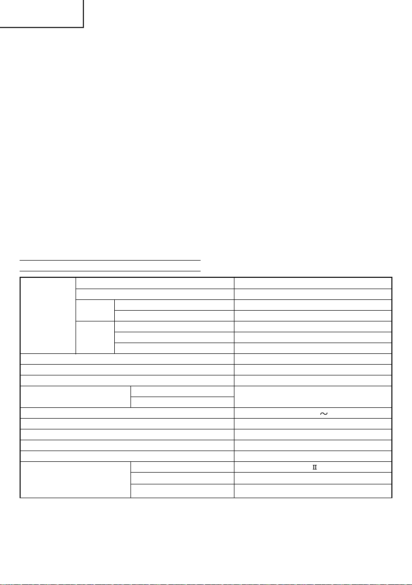
SPECIFICATIONS
0° 85 mm × 312 mm
Miter 45° 85 mm × 218 mm
Max. Cutting
Capacity
Height × Width
Saw Blade Dimensions (oD × iD × Thickness) 262 mm × 25.4 mm × 2.3 mm
Miter Cutting Angle Right 0° – 57°, Left 0° – 45°
Bevel Cutting Angle Right and Left 0° – 45°
Compound Cutting Angle
Voltage (by areas)* (220 V)
Power Input* 1090 W
No-Load Speed 3800 /min
Machine Dimensions (Width × Depth × Height) 545 mm × 1050 mm × 615 mm
Weight (Net) 19.5 kg
Laser Marker
(Only Model C10FSH)
Bevel
Compound Bevel (Right) 45° + Miter (Left) 31° 30 mm × 260 mm
Left 45° 55 mm × 305 mm
Right 45° 30 mm × 305 mm
Bevel (Left) 45° + Miter 45°
Bevel (Right) 45° + Miter (Right) 45° 30 mm × 218 mm
Bevel (Left) 0° – 45°
Bevel (Right) 0° – 45°
Maximum output Po<3 mW Class Laser Product
(Iambda) 654 nm
Laser medium Laser Diode
55 mm × 218 mm
Miter (Right and Left) 0° – 45°
* Be sure to check the nameplate on product as it is subject to change by areas.
7

English
STANDARD ACCESSORIES
(1) 262 mm TCT Saw blade (mounted on tool) .............. 1
(2) Dust bag ...................................................................... 1
(3) 10 mm Box wrench .................................................... 1
(4) Vise Assembly ............................................................ 1
(5) Holder .......................................................................... 1
(6) Sub Fence (A) ............................................................. 1
Standard accessories are subject to change without notice.
OPTIONAL ACCESSORIES (SOLD SEPARATELY)
(1) Extension Holder and Stopper
(2) Saw blade 262 mm TCT Saw blade (Total teeth: 60)
(3) Crown molding Vise Ass'y (Include Crown molding
Stopper (L))
(4) Crown molding Stopper (L)
(5) Crown molding Stopper (R)
Optional accessories are subject to change without notice.
APPLICATION
Cutting various types of aluminium sash and wood.
UNPACKING
䡬 Carefully unpack the power tool and all related items
(standard accessories).
䡬 Check carefully to make certain all related items
(standard accessories) are present.
PRIOR TO OPERATION
1. Power source
Ensure that the power source to be utilized conforms
to the power requirements specified on the product
nameplate.
2. Power switch
Ensure that the power switch is in the OFF position. If
the plug is connected to a receptacle while the trigger
switch is in the ON position, the power tool will start
operating immediately, inviting serious accident.
3. Extention cord
When the work area is removed from the power
source, use an extension cord of sufficient thickness
and rated capacity. The extension cord should be kept
as short as practicable.
4. When the power tool is prepared for shipping, its
main parts are secured by a locking pin
Move the handle slightly so that the locking pin can
be disengaged.
During transport, lock the locking pin into the gear
case (Fig. 4).
5. Attach the dust bag to the main unit (Fig. 1)
6. Installation
Ensure that the machine is always fixed to bench.
Attach the power tool to a level, horizontal work bench.
Select 8 mm diameter bolts suitable in length for the
thickness of the work bench.
Bolt length should be at least 25 mm plus the thickness
of the work bench.
For example, use 8 mm × 65 mm bolts for a 25 mm
thick work bench.
ADJUSTING THE POWER TOOL PRIOR TO USE
CAUTION
Make all necessary adjustments before inserting the
plug in the power source.
1. Check to see that the lower guard operates smoothly
CAUTION
䡬 This slide compound miter saw is equipped with a
saw head lock as safety device.
䡬 To lower the saw head to cut, the lock must be released
by pressing the lever (A) with your thumb.
(1) When you push down the handle while pushing the
lever (A), check that the lower guard revolves
smoothly (Fig. 5).
(2) Next, check that the lower guard returns to the original
position when the handle is raised.
2. Checking the saw blade lower limit position (Fig. 7)
Check that the saw blade can be lowered 10 mm to
11 mm below the table insert.
If necessary, adjust as follows:
(1) Loosen the 8 mm wing nut.
(2) Insert your 6 mm hexagon bar wrench from behind
of the tool and turn the 8 mm hexagon socket set
screw to the left (counterclockwise) viewed from
behind of the tool.
(3) Turn the 8 mm depth adjustment bolt, change the
height where the bolt head and the gear case contacts,
and adjust the lower limit position of the saw blade.
One turn of the 8 mm depth adjustment bolt changes
the lower limit position of the saw blade by about 8
mm, and this information can be used as a rough
guide.
(4) Turn the 8 mm hexagon socket set screw to the right
(clockwise) as viewed from behind of the tool, and let
it softly contact the tip of the 8 mm depth adjustment
bolt.
CAUTION
Adjust the lower limit position so that the saw blade
will not cut the turntable or complete cutting cannot
be done.
PRACTICAL APPLICATIONS
CAUTION
䡬 It is dangerous to remove or install the workpiece
while the saw blade is turning.
䡬 When sawing, clean off the shavings from the
turntable.
䡬 If the shavings accumulate too much, the saw blade
from the cutting material will be exposed. Never
subject your hand or anything else to go near the
exposed blade.
1. Tightly secure the material by vise assembly to be
cut so that it does not move during cutting
2. Switch operation
Pulling the trigger turns the switch on. Releasing the
trigger turns the switch off.
3. Base holder adjustment (Fig. 3)
Loosen the 6 mm bolt with the supplied 10 mm box
wrench. Adjust the base holder until its bottom surface
contacts the bench or the floor surface.
4. Cutting a groove on the guard
Holder (A) has a guard (see Fig. 6) into which a groove
must be cut. Loosen the 6 mm knob bolt to retract the
guard slightly.
8

English
After placing a suitable wooden piece to sit on the
fence and the table surfaces, fix it with the vise. After
the switch has been turned on and the saw blade has
reached maximum speed, slowly lower the handle to
cut a groove on the guard.
CAUTION
Do not cut the groove too quickly; otherwise the guard
might become damaged.
5. Adjusting the guard (Fig. 6)
(1) In the case of cutting at a right angle or bevel cutting:
Loosen the 6 mm knob bolt, bring the guard lightly in
contact with the materials to be cut and secure. Align
the ink line with the saw blade groove on the guard
and begin operations.
(2) In the case of miter cutting or miter cutting plus bevel
cutting:
Loosen the 6 mm knob bolt, move the guard to the
back, making sure that it is not sticking out from the
fence surface.
6. Using the Vise Assembly (Standard accessory) (Fig. 12)
The vise assembly can be mounted on either the left
fence (Fence (B)), or the right fence (Fence(A)), and
can be raised or lowered according to the height of
the workpiece. To raise or lower the vise assembly,
first loosen the 6 mm knob bolt. The vise shaft has
three locking grooves into which the tip of the 6 mm
wing bolt is designed to fit in order to lock the screw
holder in the desired position. To ensure that the tip
of the 6 mm wing bolt is properly aligned with the
desired locking groove on the vise shaft, simply align
the upper surface of the fence to either of three Vgrooves on the vise shaft surface or to the lower
surface of the screw holder. Therefore, the vise
assembly can be attached in either of three positions
to ensure proper height adjustment.
After adjusting the height, firmly tighten the 6 mm
wing bolt; then turn the upper knob, as necessary, to
securely attach the workpiece in position.
WARNING
Always firmly clamp or vise to secure the workpiece
to the fence; otherwise the workpiece might be thrust
from the table and cause bodily harm.
CAUTION
Always confirm that the motor head does not contact
the vise assembly when it is lowered for cutting. If there
is any danger that it may do so, loosen the 6 mm wing
bolt and move the vise assembly to a position where it
will not contact the saw blade.
7. Positioning the table insert (Fig. 1)
Table inserts are installed on the turntable. When
shipping the tool from the factory, the table inserts
are so fixed that the saw blade does not contact them.
The burr of the bottom surface of the workpiece is
remarkably reduced, if the table insert is fixed so that
the gap between the side surface of the table insert
and the saw blade will be minimum. Before using the
tool, eliminate this gap in accordance with the
following procedure.
Loosen the three 6 mm machine screws, then secure
the left side table insert and temporarily tighten the 6
mm machine screws of both ends. Then fix a
workpiece (about 200 mm wide) with the vise
assembly and cut it off. After aligning the cutting
surface with the edge of the table insert, securely
tighten the 6 mm machine screws of both ends.
Remove the workpiece and securely tighten the 6 mm
center machine screw. Adjust the right hand table
insert in the same way.
CAUTION
After adjusting the table insert for right angle cutting,
the table insert will be cut to some extent if it is used
for bevel angle cutting.
When bevel cutting operation is required, adjust the
table insert for bevel angle cutting.
8. Confirmation for use of sub fence
This power tool is equipped with a sub fence. In the
case of direct angle cutting and right bevel angle
cutting, use the sub fence. Then, you can do Left bevel
angle cutting, Right bevel angle cutting and Direct
angle cutting and realize stable cutting of the material
with a wide back face.
WARNING
In the case of left bevel cutting, turn the sub fence
counterclockwise (Fig. 8). Unless it is turned
counterclockwise, the main body or saw blade may
contact the sub fence, resulting in an injury.
9. Confirmation for use of sub fence (A) (Fig. 11)
In the case of direct angle cutting and angle cutting,
use the sub fence (A). The sub fence (A) can be
installed on the right side of the guide fence. Insert
the rods of the sub fence (A) into the holes in the guide
fence. Tighten the 6 mm bolt which come with the
sub fence (A) to secure the sub fence (A). Then, you
can realize stable cutting of the material with a wide
back face.
WARNING
In the case of right bevel cutting, remove the sub fence
(A). Supposing it is not able to remove it, it will contact
the blade or some part of the tool, causing in serious
injury to operator.
10. Using an ink line
(1) Right angle cutting
Loosen the 6 mm knob bolt and contact the tip of the
guard with the workpiece.
Aligning the ink line on the workpiece with the groove
of the guard, the workpiece is cut on the ink line.
(2) Miter cutting and compound cutting (Miter cutting +
bevel cutting)
Upon lowering the motor section, the lower guard is
raised and the saw blade appears.
Align the ink line with the saw blade.
CAUTION
In some arrangements when the turntable is rotated,
the guard projects from the fence surface. Loosen the
6 mm knob bolt and push the guard to the retracted
position. Never lift the lower guard while the saw
blade is rotating. When cutting at an angle of 35° to
the right or more, please slide the guard to the rear.
The guard and sub-fence will not only make contact
and adversely affect cutting accuracy, this could also
result in damage to the guard.
11. Position adjustment of laser line (Only Model C10FSH)
Ink lining can be easily made on this tool to the laser
marker. A switch lights up the laser marker (Fig. 14).
The laser line is adjusted to the width of the saw blade
at the time of factory shipment. Adjust the positions
of the saw blade and the laser line taking the following
steps to suit the use of your choice.
9
 Loading...