


Hi-G-Tek Ltd. Microelectronics and Asset Tracking Technology
User’s Manual
Ver. A 61 UM4710

INTRODUCTION....................................................................... 10
1
1.1 W
1.2 A
1.3 S
HAT PRODUCTS ARE COVERED BY THIS MANUAL
BOUT TH E PRO DUCT
YSTEM COMPO NENTS
............................................................... 10
.............................................................. 14
.................. 10
1.3.1 The Mounting Fixture............................................................ 14
1.3.2 The Dat aSeal ........................................................................ 14
1.3.3 Sealing Wire......................................................................... 15
1.3.4 Outdoor DataReader.............................................................. 15
1.3.5 Indoor DataReader ................................................................ 17
2 Q UICK-START .......................................................................... 20
2.1 B
2.2 S
2.3 I
2.4 C
2.5 P
2.6 E
2.7 A B
EFOR E YOU BEGIN
ETTING UP TH E DATAREADERS
NSTALLING THE EVALUATION SOFTWARE
ONF IGURING TH E SYSTEM
REPARING TH E DATASEAL/DATATAG
XECUTING A VERIFY COMMAND
RIEF TUTORIAL THROUGH THE STATES O F TH E DATASEAL
................................................................... 20
............................................... 21
............................... 21
...................................................... 22
..................................... 24
.............................................. 27
29
3 DATAS EAL INSTALLATIO N................................................... 34
4 DATA TAG INSTA LLA TION..................................................... 38
4.1 P
LACING TH E DATATAG O N A VEHICLE
.................................... 38
4.1.1 Horizontal Orientation:.......................................................... 39
- 2 - Hi-G-Tek Ltd. Micro el ec tro nic s & A sset Tra ck ing Te ch no logy

4.1.2 Vert ical Orientation............................................................... 39
5 DATAREADER INSTALLA TION ............................................. 42
5.1 O
UTDOOR DATAREADER INSTALLATIO N
.................................. 42
5.1.1 Ceiling Installat ion................................................................ 42
5.1.2 Connecting the Outdoor Unit ................................................. 43
5.1.3 Wiring the Outdoor DataReader............................................. 44
5.1.4 RS-232 Wiring Diagram........................................................ 45
5.1.5 RS-485 Full Duplex Wiring Diagram...................................... 46
5.1.6 RS-485 Half Duplex Wiring Diagram..................................... 46
5.1.7 DataReader Configuration Switches ....................................... 46
5.2 I
NDOOR DATAREADER INSTALLATION
...................................... 47
5.2.1 Connecting the Indoor Unit.................................................... 47
5.2.2 Wiring the Indoor DataReader................................................ 48
5.2.3 RS-232 Wiring Diagram........................................................ 49
5.2.4 RS-485 Full Duplex Wiring Diagram...................................... 50
5.2.5 RS-485 Half Duplex Wiring Diagram..................................... 51
5.3 C
5.4 RS -232/RS - 48 5 A
HA INING DATAREADERS TO G E TH ER
DAPTER
.......................................................... 54
...................................... 51
5.4.1 Connecting the RS-232/RS-485 Adapter to the First DataReader
54
5.4.2 Connecting the RS-232/RS-485 Adapter to the Controlling
Computer 56
5.5 P
OWER SUPPLY REQUIREMENTS
............................................... 56
5.5.1 General................................................................................. 56
5.5.2 Indoor Installation................................................................. 57
5.5.3 Outdoor Installation............................................................... 57
5.6 C
5.7 I
5.8 D
ABLE SELECTION
NSTALLATIO N NOTES
ATAREADER OPERATION INSTRUCTIONS
.................................................................... 58
............................................................... 59
................................ 60
Hi-G-Tek Ltd. Micro electro nics & Asset Tracking Technology - 3 -

5.8.1 Power Indicators:.................................................................. 60
5.8.2 Channel 1 SD/RD Indicator:.................................................. 60
5.8.3 Channel 2 SD/RD Indicator:.................................................. 61
6 SYSTEM O VERVIEW................................................................ 64
6.1 S
6.2 D
YSTEM DESCRIPTION
ATASEAL A ND DATAREADER MODES O F OPERATION
............................................................... 64
............. 66
6.2.1 DataSeal Modes of Operation................................................. 66
6.2.2 DataReader Modes of Operation............................................. 68
6.3 M
OST COMMON COMMANDS AND SEA L STATU S
....................... 69
6.3.1 Most Commonly Used Commands......................................... 69
6.3.2 DataSeal's Status................................................................... 70
6.4 S
YSTEM PLANNING
................................................................... 71
6.4.1 Electromagnetic Environment ................................................ 72
6.4.2 System Layout ...................................................................... 72
6.4.2.1 Radio Frequency Communication Layout............................. 73
6.4.2.2 Line Communication RS-485 Layout.................................... 74
6.5 S
YSTEM S SEGREGATION
........................................................... 75
6.5.1 Companies Segregation by OrgID .......................................... 76
6.5.2 Department Isolation............................................................. 76
6.5.3 Services to Several Companies by a Service Provider.............. 77
6.5.4 Subgroups of DataSeals......................................................... 77
6.5.5 OrgID, Department, Global and ADI Impact on DataSeal’s
Response 78
6.6 D
ATASEAL'S MEMOR Y
.............................................................. 79
6.6.1 Events Memory..................................................................... 79
6.6.2 User Dat a.............................................................................. 80
6.6.2.1 The User Data portion used by the DataT erminal................... 81
6.7 S
YSTEM COMMANDS
................................................................. 82
- 4 - Hi-G-Tek Ltd. Micro el ec tro nic s & A sset Tra ck ing Te ch no logy

7 EVALUATIO N SO FTWARE...................................................... 88
7.1 S
7.2 C
W
OFTWARE INSTALLATIO N
OMMUN ICATION SETUP
INDOW
............................................................................................ 89
........................................................ 88
HE READERS ADM INISTRA TION
– T
7.2.1 Defining the Connected DataReaders...................................... 89
7.2.2 Setting Up the Communication Port........................................ 90
7.3 R
7.4 T
EADER SETUP
HE VERIFY AND SET WINDOW
......................................................................... 90
................................................. 91
7.4.1 Executing Broadcast Verify Command................................... 94
7.4.2 Executing Addressed Verify Command.................................. 96
7.4.3 Executing Set Command........................................................ 98
7.4.4 Cyclical Interrogations Options.............................................. 99
7.5 E
W
XECUTING ANY COMMAND USING THE ALL COMMANDS
INDOW
.......................................................................................... 100
7.5.1 Executing an RF Command ................................................. 101
7.6 S
PECIFIC COMMAND STRUCTURES
.......................................... 102
7.6.1 Verify................................................................................. 103
7.6.2 T ampered (T amper)............................................................. 105
7.6.3 Addressed Verify ................................................................ 105
7.6.4 Set 106
7.6.5 Soft Set............................................................................... 107
7.6.6 Suspended Set..................................................................... 107
7.6.7 Read Data........................................................................... 108
7.6.8 Write Dat a.......................................................................... 110
7.6.9 Read Parameters.................................................................. 112
7.6.10 Write Parameters................................................................. 113
7.6.11 Reset Data.......................................................................... 115
7.6.12 Deep Sleep.......................................................................... 116
7.6.13 Hard Wakeup...................................................................... 117
7.6.14 Start Alert Burst Mode......................................................... 118
Hi-G-Tek Ltd. Micro electro nics & Asset Tracking Technology - 5 -

7.6.15 Start Alert Burst Mode (all).................................................. 119
7.6.16 Stop Alert Burst Mode......................................................... 120
7.6.17 Stop Alert Burst Mode (all).................................................. 120
7.6.18 Acknowledge Alert Burst..................................................... 121
7.6.19 Read Events........................................................................ 122
7.7 A
DVANCED FEATURES
............................................................. 124
7.7.1 Built-In Test....................................................................... 124
7.7.2 Authorization Levels and Passwords..................................... 125
7.7.2.1 Logging-in Using the Desired Authorization Level.............. 126
7.7.2.2 Changing Passwords.......................................................... 126
7.7.3 Updating the DataReader's Internal Software......................... 127
7.7.3.1 The MCU Download Utility............................................... 128
7.7.3.2 RF Modem Download Utility............................................. 129
8 S YSTEM PARAMETERS AND CO MMANDS ........................ 132
8.1 T
HE HIGH FREQ UENCY
RF P
ROTOCOL
................................... 132
8.1.1 The Basics.......................................................................... 132
8.1.2 Addressing Types................................................................ 134
8.1.3 The Slotted Aloha Concept .................................................. 135
8.2 D
ATASEAL PARAMETERS
........................................................ 136
8.2.1 The Dat aSeal Status Flags.................................................... 167
8.3 E
VENTS
................................................................................... 179
8.3.1 General Structure of an Event Record................................... 180
8.4 H
IGH-FREQUENCY
OMMANDS SUMMA RY
RF C
........................ 186
8.4.1 Broadcast Commands.......................................................... 187
8.4.2 Addressed Commands......................................................... 195
8.4.3 Multi Addressed Commands................................................ 204
8.4.3.1 Multi Addressed Commands With Parameters..................... 204
8.4.3.2 Multi Addressed Commands Without Parameters................ 205
8.5 B
- 6 - Hi-G-Tek Ltd. Micro el ec tro nic s & A sset Tra ck ing Te ch no logy
URST MESSAGES
................................................................... 210

8.6 D
8.7 C
ATAREADER PAR AMETERS
OMMAND CHAIN
................................................................... 230
................................................... 215
9 TRO UBLE S HOO TING AND PROBLEM SO LVING ............. 234
9.1 G
9.2 RS-232/485 C
9.3 G
9.4 S
ENERAL DATAREADER PROBLEM S
OMMUNICATION PROBLEM S
ENERAL
PECIFIC
OMMUN ICATION PRO BLEM S
RF C
CO MMANDS TROUBLESHOOTING
RF
....................................... 234
.............................. 234
........................... 234
:....................... 235
10 TECHNIC AL SPECIFICATIONS............................................ 238
10.1 24V O
10.2 12V O
10.3 48V O
10.4 24V I
10.5 12V I
10.6 48V I
10.7 D
10.8 M
10.9 FC C
UTDOOR DATAREADER
UTDOOR DATAREADER
UTDOOR DATAREADER
NDOOR DATAREADER
NDOOR DATAREADER
NDOOR DATAREADER
ATASEAL
AGNETICDATASEAL
.............................................................................. 244
APPROVED PRODUCTS
.................................................. 238
.................................................. 239
.................................................. 241
..................................................... 242
..................................................... 243
..................................................... 243
............................................................. 245
:.................................................... 246
11 INDEX....................................................................................... 250
Hi-G-Tek Ltd. Micro electro nics & Asset Tracking Technology - 7 -

This User’s Manual includes all the information required for installing
and operating Hi-G-T ek Electronic DataSeals and DataReaders.
Software License Agreement
Information in this do cument is subject to change without notice and does not
represent a commitment on the part of the manu facturer. The software described in
this document is furnished under licens e agreement or nondisclosure agreement. It
is against the law to copy the software on any medium except as speci fi cally
allowed in the license or nondisclosure agreem ent. T he purchaser may make one
copy of the softw are for backup purposes. No part o f this manual may be
reproduced or transmitted in any form or by any means, electronic or m echanical,
including photocopying, recording, or in fo rmation storage and retrieval, for any
purpose other than fo r the purchaser’s personal use, without written permission.
© Copyright 2001 Hi-G-Tek Ltd.
All rights reserved.
DataSeal
Pentium
Microsoft Windows 98
TM
is a trademark of Hi-G-T ek.
TM
is a trademark of Intel Corporation.
®
and Microsoft Windows NT® are trademarks of
Microsoft Corporation.
Moxa is a trademark of Moxa Technologies.
- 8 - Hi-G-Tek Ltd. Micro el ec tro nic s & A sset Tra ck ing Te ch no logy


Chapter 1 Introduction
1
Introduction
1.1 What Products are Covered by this Manual
This manual covers the DataReader (both Indoor and Outdoor versions),
Dat aSeal, Dat aT ag and th e Magnet icDat a Seal p roduct s.
The DataTerminal, DataPort, MicroDataReader, T rackingDataReader and
Smart DataReader are Hi-G-T ek products that are referred to in some places
in the manual, but are not covered by it.
1.2 About the Product
Thank you for choosing Hi-G-T ek quality product s. The Hi-G-T ek range of
product s provides a h igh ly reliable and secure car go an d asse t monitoring
system utilizing stat e-of-the-art RFID technologies.
Cost-effective, more reliable and more secure than their mechanical
counterparts, the Hi-G-Tek product range will const ant ly monitor your
assets and alert you to any potential problems at all times.
The Hi-G-Tek syst em was developed in order to fill the requirement for
fast, automatic processing of secured cargoes and to provide real t ime
mon ito r ing and im pr ov ed managem ent of cargoes bot h in t ransit an d in
storage.
The basis of the system is a family of reusable electronic seals named
DataSeal. Th is family of p ro duct s in cludes t he DataSeal, DataT ag and t he
MagneticDataSeal.
- 10 - Hi-G-Tek Ltd. Micro el ec tro nic s & A sset Tra ck ing Te ch no logy

Chapter 1 Introduction
Note: T his manual uses the t erm DataSeal to refer to any member of this
fam ily o f p ro duct s, unless oth erwise sp ecified.
The most significant purposes of the Dat aSeal are:
Track any attempts of opening, bypassing or tampering.
Record events when tamper occurs.
Write and read user data.
The reusable electronic seal automates the processing of secured cargoes
enabling the organization to effectively and economically process t he
increasing numbers of containers’ traffic in the ports and between inland
destinations.
The DataSeal includes a transmitter / receiver unit, real-time clock,
processor, memory and sensing circuitry for sealing verification. The
Sealing Wire
1
prevents any attempt of opening, bypassing or tampering
with the seal without alert ing the syst em and recording of the event. The
system combines t he technological and operat ional advantages of both low
frequency close-range AND high frequency (UHF) long range for sealing
verification and other communications with the DataSeal.
The low frequency (short range) communication protocol is used by the
DataTerminal, t he DataPort and t he MicroDataReader. This channel of
communication is useful for writing the electronic manifest of the sealed
cargo into the DataSeal's memory. For example: this information can
1
In t he case o f DataT ag, there's a “ S ensor Plate” instead o f t he Sealing Wire, and
in the case of the MagneticD ataS eal , there's a “ Magnet Element”.
Hi-G-Tek Ltd. Micro electro nics & Asset Tracking Technology - 11 -

Chapter 1 Introduction
include the vehicle ID, container and invoice numbers, cargo description,
etc. It is also useful for reading the DataSeal's event records, and t o reset
the DataSeal for a new use (an operation called "Set").
Note:
The low frequency protocol, the DataTerminal, DataPort and
MicroDataReader devices are not covered by this manual.
The high frequency protocol is used by devices of the DataReader family of
products. This family includes the DataReader it self, which connects to a
controlling computer (normally a PC) t hrough an RS-232/485 interface; the
TrackingDataReader which cont ains a GPS and GSM modules and is
usually installed on a truck; and t he SmartDat aReader which contains an
embedded PC and connects to an Ethernet network. This manual covers
only th e DataReade r device itself. The high frequen cy pr otocol is use f ul for
monitoring the presence and status of one or more DataSeals constantly or
periodically. It is capable of communicating with multiple DataSeals
simultaneously and even with DataSeals in high speed motion, for
example: on a train.
The DataSeal and DataReader devices are capable of communicating in
distances of up to 30 meters, and in some cases even more.
The use of the high frequency/long range protocol enables applications
such as: tracking and sealing verification of containers in transit; protection
of containers in storage; remote automatic data collection from secured
cargoes as they pass through check points, etc.
The DataReader is able t o detect which DataSeals are present in its area,
and their statuses (open/close, tampered, etc). It can also receive messages
from DataSeals in real-time, for example when the DataSeal is tampered.
These types of messages that the Dat aSeal transmit s are called "Burst
Messages" .
- 12 - Hi-G-Tek Ltd. Micro el ec tro nic s & A sset Tra ck ing Te ch no logy

Chapter 1 Introduction
Multiple DataReaders can be connect ed to a single controlling computer
using the RS-485 interface. This allows to maximize the coverage area of
the DataReaders while keeping them synchronized. The Dat aReader is
av ailable in both in doo r and o utdoor mo dels.
A set of Mount ing Fix t ures has been de v eloped for t he Dat aSeal syst em
which allow convenient mounting and removal of the DataSeal from a
co ntainer when ev er r equir e d. Th e v ario us Mount ing Fix t ures differ in the
level of protection they provide to the DataSeal as may be required in
various environments.
Hi-G-Tek Ltd. Micro electro nics & Asset Tracking Technology - 13 -
Chapter 1 Introduction
1.3 System Compone nts
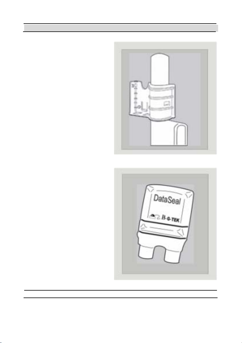
1.3.1 The Mounting
Fixt u re
The Dat aSeal Mount in g Fixt ure
is used to mount the DataSeal on
the cont ainer’s keeper bar or
other surface.
1.3.2 The DataSeal
The DataSeal unit contains t he
DataSeal electronics, a battery, a
transceiver, a processor and
m e mo ry t o r eco r d an d stor e t h e
events and the relevant
information about the cargo.
- 14 - Hi-G-Tek Ltd. Micro el ec tro nic s & A sset Tra ck ing Te ch no logy
Chapter 1 Introduction
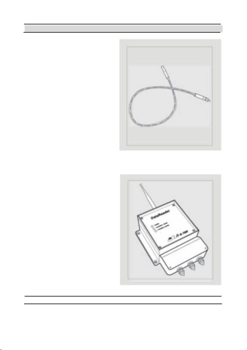
1.3.3 Sealing Wire
The Sealing Wire serves t o seal
the cargo. Any tampering with the
Sealing Wire at any p o int during
transport is recorded and can be
reported at once.
1.3.4 Outdoor DataReader
The Hi-G-Tek DataSeal System
uses st at e-of-t he-art t echnology to
secure and monit or secured
cargoes in storage and during
transport.
The DataReader is comprised of
two compartments. The upper
compart ment is the heart of the
unit and co nt ains the
DataReader’s electronics sect ion.
The lower compart ment cont ains
the terminal glands which connect
Hi-G-Tek Ltd. Micro electro nics & Asset Tracking Technology - 15 -
Chapter 1 Introduction
the unit to the RS-232/485 networking cable.
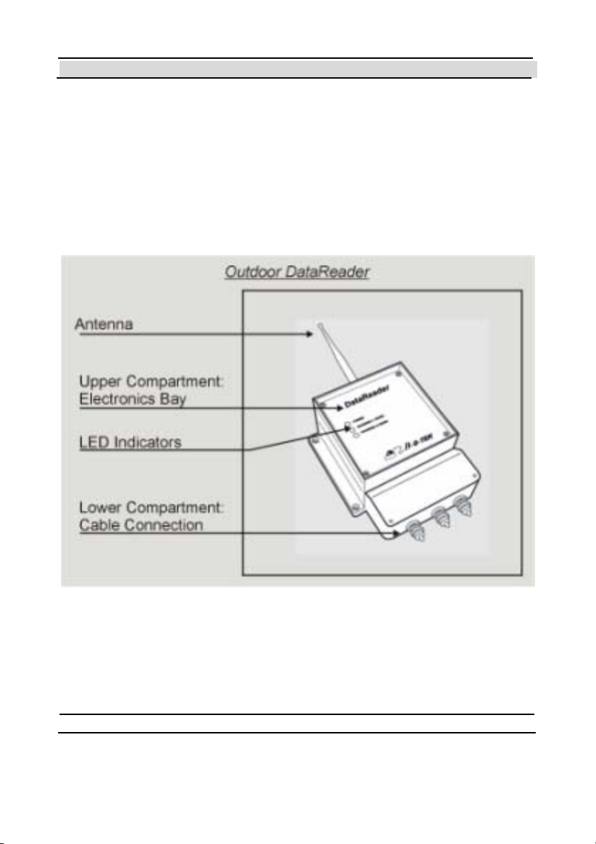
The Dat aReade r may be used in bo th station ary and mobile configurat ions.
In the st ationary configuration, the unit is mounted on a flat surface such as
a wall or pole. A typical installation of this configuration is at the point of
exit from ports, customs t erminals, warehouses, etc. This operation mode
allows monitoring of the Dat aSeal at predetermined sites and checkpoints.
In the mobile configur at ion, t he unit is mount ed in t he t ruck cabin . T he
DataReader monitors the seal during t he entire journey, and reports its
status via the vehicle’s communication system to the control center in realtime. T his configurat ion requires an addit ional 3rd party controlling device
to cont rol the Dat aReader, or to use the T rackingDataReader which is not
covered by this manual.
- 16 - Hi-G-Tek Ltd. Micro el ec tro nic s & A sset Tra ck ing Te ch no logy
Chapter 1 Introduction
The DataReader is mast ered by a controlling computer. Once installed, the
unit waits for commands coming from the controlling computer.
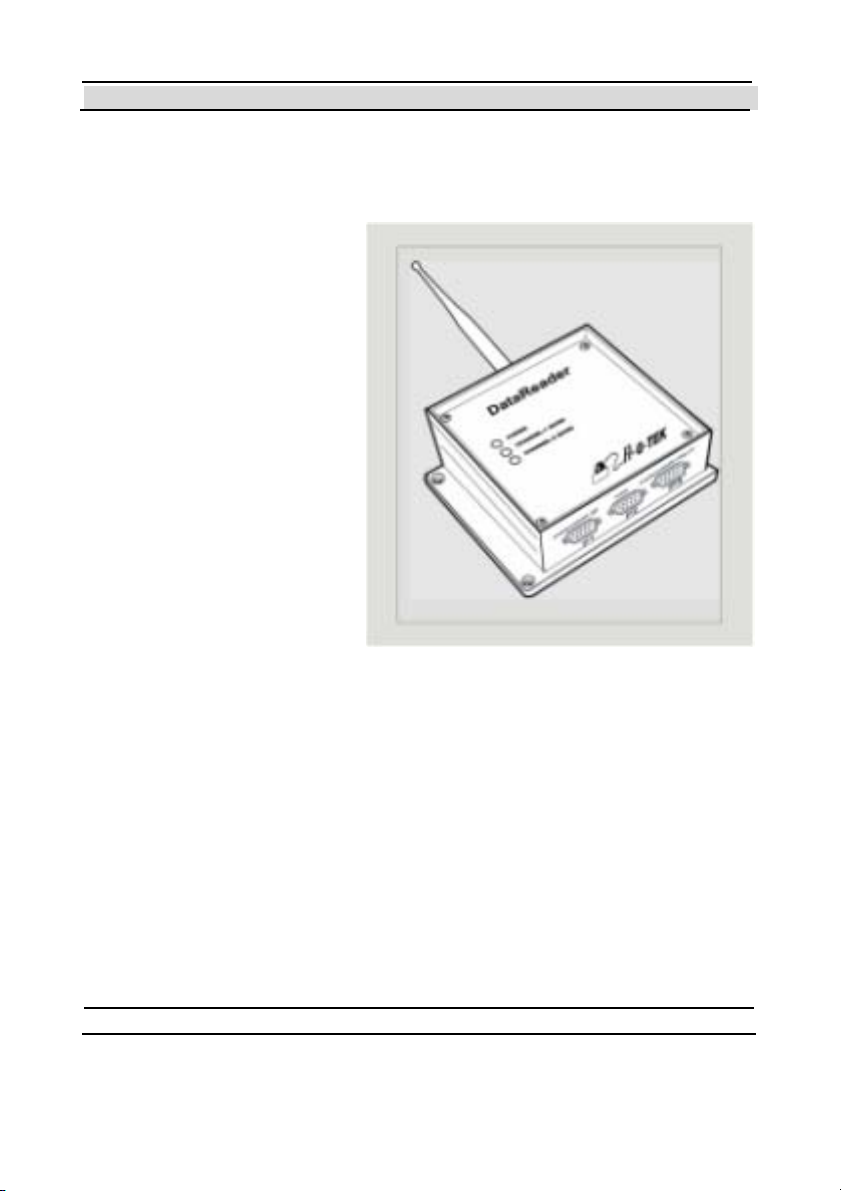
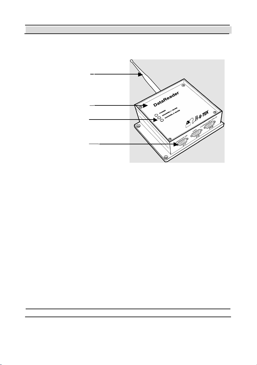
1.3.5 Indoor
Data Re ader
Similar to the outdoor
version, the Indoor
DataReader uses state-of-the-
art technology to secure and
monitor secured cargoes in
an indoor environment.
The Indoor DataReader may
be use d in st at io n ary
configuration only.
The unit is mounted on a flat
surface such as a wall or
pole. A typical installation of
this configuration is at the
point of closed warehouses, offices, etc.
Unlike the Outdoor DataReader, the Indoor version does not have the lower
compart ment. Instead it has 3 connectors.
Hi-G-Tek Ltd. Micro electro nics & Asset Tracking Technology - 17 -
Chapter 1 Introduction
Indo or Data Reade r
Antenna
Electronics Bay
Led I n dicat or
Cable Connection
- 18 - Hi-G-Tek Ltd. Micro el ec tro nic s & A sset Tra ck ing Te ch no logy


Chapter 2 Quick Start
2
Quick-Start
The aim of this chapter is to lead you step-by-step in the quickest way to
the stage where you can verify that the Demo System is working properly,
an d that yo u h ave a simp le sy stem that yo u can p lay with , in o r der t o
ev aluat e the p otent ial of th e pro duct s. Th is guide a ssum es t hat t he
parameters of the DataReader and DataSeal are the factory defaults, and it
refers only to the Demo System. For installation instructions for a
DataReader that is not a Demo System, see chapter 5.
2.1 Be fore you begin
Before you begin, make sure that you have the following items available:
1. The Hi-G-Tek DataReader
device.
2. DataReader Antenna.
3. At least one Hi-G-Tek DataSeal device.
4. The Seal ID of the DataSeal (printed on t he sticker on the bottom side
of the DataSeal).
5. Sealing W ire( s) (accordin g to the number of DataSeals. I f yo u are usin g
DataTags you need Sensor Plate(s) instead of the Sealing Wires)
6. P C runnin g one o f the following op erat ing sy st ems:
• Windows 98 or above.
• Windows NT 4.0 or above.
- 20 - Hi-G-Tek Ltd. Micro el ec tro nic s & A sset Tra ck ing Te ch no logy

Chapter 2 Quick Start
This computer must have at least one available serial communication
port, a CD-ROM drive, and at least 20MB of free hard disk space. T he
computer must use an Intel Pentium
TM
or compatible processor.
7. CD-ROM with Evaluation Software.
2.2 Setting up the DataReaders
First, connect the antenna to the DataReader. The antenna connects to the
TNC connector at the top side of the Dat aReader.
Then, connect the DB9 female connector to a serial communication port in
t he PC. T ake not e of which p ort you ar e using (for examp le COM2). It is
good practice to connect and disconnect cables only when the computer is
off.
Plug the power chord of the Dat aReader into a power outlet. You should
see the POWER LED blinking red and green. Aft er about 30 seconds it
should remain green. If it remains red, or isn't lit at all, there is a problem
with the DataReader. Refer to the chapter 0 for troubleshooting.
2.3 Installing the Evaluation Software
If the computer is not turned on, turn it on now, and wait until the operating
system is loaded completely.
Insert the CD-ROM labeled "Hi-G-T ek" into t he CD-ROM drive.
From the Start menu, choose "Run". Assuming your CD-ROM drive is
drive E, type "E:\DataSeal Evaluation Software\Setup.EXE" in the "Run"
dialog box. If your CD-ROM drive lett er is not E, replace t he fir st E wit h
your CD-ROM drive letter. Click OK to st art installing t he DataSeal
Evaluation Software.
Hi-G-Tek Ltd. Micro electro nics & Asset Tracking Technology - 21 -

Chapter 2 Quick Start
Follow t he instructions on the screen until it says that the software is
successfully installed.
If you're using Windows 98, restart your computer (even if you're not
requested to by t he installation soft ware).
The Evaluat ion Soft war e is now in st alled. A new short cut icon "
Dat aSeal E v aluat ion" is added t o yo ur St art - >Pro gr ams m enu.
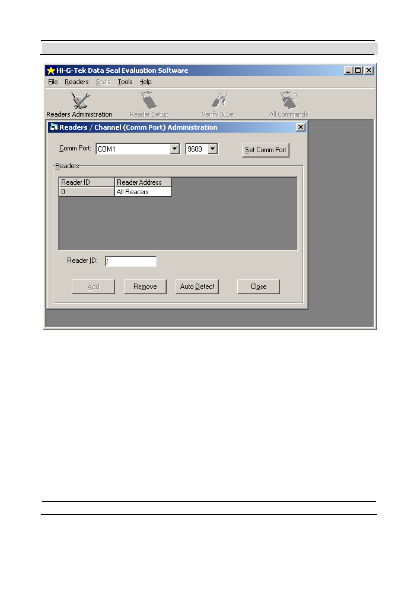
2.4 Configuring the System
Run the Evaluation Software by clicking on that icon. The Rea de rs
Admini stration Window shown in Figure 2-1 will be displayed.
- 22 - Hi-G-Tek Ltd. Micro el ec tro nic s & A sset Tra ck ing Te ch no logy
Chapter 2 Quick Start
Figure 2-1 - The Readers Administration Window.
If you connect ed the Reader to a serial port other than COM1, choose the
appropriate COM port from the Comm Port drop do wn list , an d t hen click
on the Se t Comm Port butt on. Click OK to close t he message window that
says "Comm port was set successfully".
Click on the Au to De tec t button on the bottom of the window, to
automatically find the Reader ID of t he DataReader. The message shown in
Figure 2-2 will be displayed.
Hi-G-Tek Ltd. Micro electro nics & Asset Tracking Technology - 23 -

Chapter 2 Quick Start
Figure 2-2 - Auto Detect Warning Message.
Because you're using the Demo System that includes only one DataReader,
click Ye s .
If everything is connect ed appropriately, a message window will appear
saying "Reader was added successfully". Click OK to close this message.
If inst ead of this message, a "T imeout " message appears, check your
connections and verify that the communication port setting corresponds to
t he on e yo u're usin g. Remember t o click on Set Comm Port each t ime you
change the communication port setting.
If a different message appears, refer to chapter 9 for troubleshooting.
The DataReader's ID is now added to the list with a Reader Address of 1.
Click on the Close button to close the Re a de rs A dmini str ati on win do w.
2.5 Preparing the DataSeal/DataTag
DataSeals provided by Hi-G-T ek leave the factory in a special power
saving mode called "Deep Sleep Mode". Before you can communicate
normally with a DataSeal, you must send it a special command called
"Hard Wakeup" that returns the DataSeal into its normal mode of
operation. You will t hen have t o close the Sealing Wire (as will be
- 24 - Hi-G-Tek Ltd. Micro el ec tro nic s & A sset Tra ck ing Te ch no logy
Chapter 2 Quick Start
explained below), and send another command called "Set" that prepares t he
DataSeal for normal operation.
This section describes how to prepare a single DataSeal. If you have more
than one DataSeal, repeat all the instructions in this section for each
Dat aSeal yo u have.
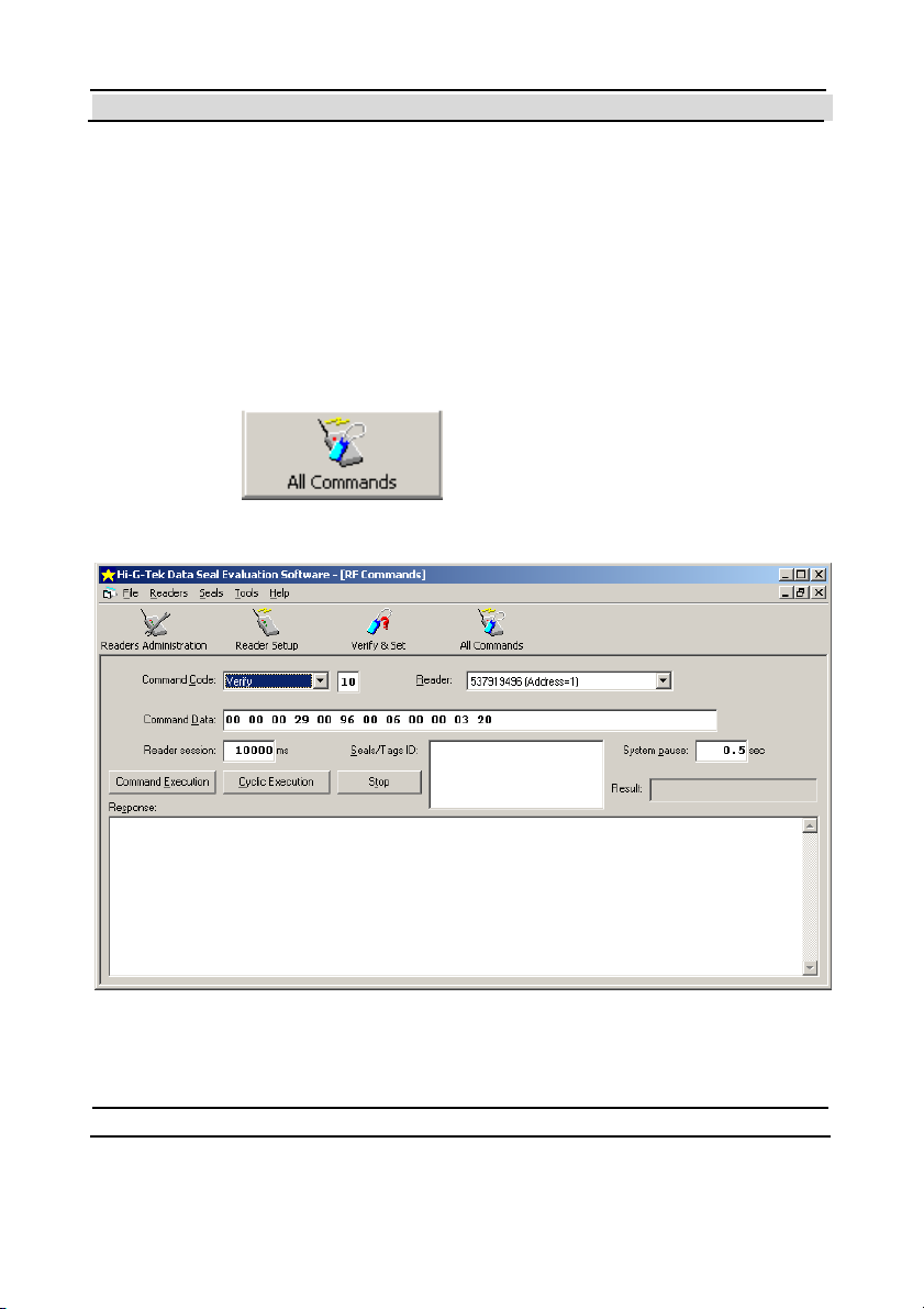
In order to send the Hard Wakeup command to the DataSeal or DataSeals
do the following:
Click on the
button on the tool bar to open the
window shown in Figure 2-3.
Figure 2-3 - All Commands Window.
Hi-G-Tek Ltd. Micro electro nics & Asset Tracking Technology - 25 -

Chapter 2 Quick Start
From the Command Code dr op do wn list , select Har d Wakeu p.
Copy the Seal ID of the DataSeal you want to wake up into the Seals/Tags
ID t ext box. The Seal ID is pr int ed o n the st icker on the bottom o f t he
DataSeal.
Click the Command Execution button. The mouse cursor will change to
an hourglass icon for about 11.5 seconds and then return to a normal
pointer cursor.
If the DataSeal received the message, The Res ult box will show the
message "Command OK" in green letters. If not, verify that you typed the
Seal ID correctly in the Seals/Tags ID box, and that the DataSeal is nearby,
and try again. If you still don't get the green "Command OK" message, or
you see a different r ed m essage in th e Re su l t box, refer to chapter 9 for
troubleshooting.
If yo u're usin g a DataSeal (as op po sed to a Dat aTag), y o u no w h ave t o
close the Sealing Wire by inserting its 2 ends t o the 2 socket s in the
DataSeal. Push the ends inside the sockets as far as you can. (You should
hear a 'Click' when the wire end is fully inserted). If you're using a
DataTag, you should place the Sensor Plate in its appropriate place at the
bott om of the Dat aT ag.
From the Command Code drop down list , select Set and then click the
Command Execution button. After about 4 seconds, a green "Command
OK" message should appear in the Re sul t box.
Congratulations! Now your DataSeal is prepared for normal operation!
- 26 - Hi-G-Tek Ltd. Micro el ec tro nic s & A sset Tra ck ing Te ch no logy
Chapter 2 Quick Start
2.6 Executing a Verify command
As a m att er of fact, if everyt h ing worked fine up to th is point , yo u can be
sure t hat your Demo System is workin g. Nevertheless, yo u pro bably wan t
to know how to perform some basic operations.
The most commonly used command is the Verify command. The main
purpose of this command is to detect which DataSeals are currently around,
and their status (opened/closed, tampered/not tampered).
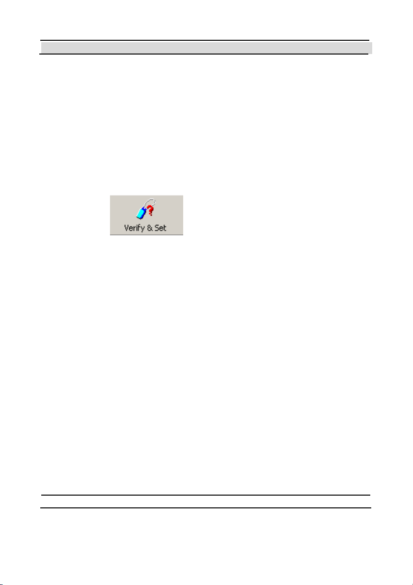
In order to execute a Verify command, open the Ve ri fy & S e t window, by
clicking on the
button on the tool bar. The window shown
in Figure 2-4 will be displayed.
Hi-G-Tek Ltd. Micro electro nics & Asset Tracking Technology - 27 -

Chapter 2 Quick Start
F igure 2-4 - The Ve rify & Se t W indow .
Note that there are 2 buttons labeled "Single Interrogation": the upper one
resides in a rectangle labeled "Broadcast Verify", and the lower one in a
rect angle labeled "Address Verify and Set ". In this guide, we'll on ly use t he
upper one (Broadcast Verify). Click this button now. After about 5 seconds,
one or more lines will be added to the list, according to the number of
DataSeals that were detect ed.
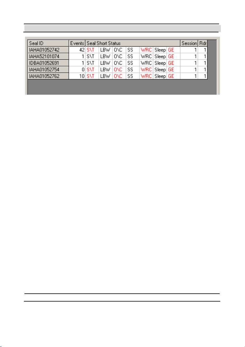
Figure 2-5 shows an example of a list with 5 detect ed DataSeals.
- 28 - Hi-G-Tek Ltd. Micro el ec tro nic s & A sset Tra ck ing Te ch no logy
Chapter 2 Quick Start
Figure 2-5 - 5 DataSeals Detected.
Clicking the Single Interrogation button again will add another one or
more lines to the list. To clear the list, click on the Rese t butto n at t he
bottom of the window.
A complete explanation about the results you see is out of the scope of this
Quick-Start chapter. Nevertheless, t here are 2 flags in t he DataSeal's Short
Status that are worth a brief explanation here.
2.7 A Brief Tutorial Through the States of the DataSeal
The DataSeal has many flags that determine its state, as well as Parameters,
Event Records and User Data. Even though most of these feat ures are out
of the scope of this chapter, 2 of the flags represent the most fundamental
concepts of the DataSeal. T hese flags are the Tampered flag (shown in
Figure 2-5 as "S/T"), and t he Opened flag (shown in Figure 2-5 as "O/C").
Note that in the Evaluation Soft ware, flags that are set appear in red, while
unset flags appear in black.
If you have followed t his guide st ep by step up to t his po int, y ou should
have both flags off (black). If you cleared the list, click Single
Interrogation (the upper one) again to see the flags.
Hi-G-Tek Ltd. Micro electro nics & Asset Tracking Technology - 29 -

Chapter 2 Quick Start
The Opened flag is set (on) whenever the Sealing Wire is open, and unset
(off) whenever it is closed. That explains why the O/C flag appears black.
Now, open the Sealing Wire by pulling one of its ends out of the socket.
Click t he Single Interrogation button again to see that the O/C flag has
turned red (on).
You may have not iced that also the S/T flag has become red. This indicat es
that the DataSeal was Tam pered. If you now close the Sealing Wire, this
flag will remain on, even t hough the Opened flag will turn off again. Try it
now: close the wire, and click the Single interrogation once more. You
should see the O/C flag black again, but the S/T remains red.
No matter how many times you would open and close the wire now, the
Tampered flag remains set, to indicate that it was opened at least once.
Yo u can try it if yo u want.
Yo u may be won derin g by now, whet her this tutorial led y o u to a st at e
where the DataSeal is irreversibly tampered, meaning t hat the DataSeal is
no longer usable! Well, you can relax because the Hi-G-Tek Dat aSeal is a
reusable seal, meaning that you can c l ea r th at Tampered flag. The
Tampered flag can be cleared only when the Sealing Wire is closed, and it
is done by sending a Set command to the DataSeal. That’s right, that's the
same command you sent aft er the Hard Wakeup in the "Preparing the
Seal/T ag" sect ion.
You can send this command from the Ve ri fy & S e t windows too. After
performing a Single In te rrogation, click on the line in the list that shows
the Seal ID of the DataSeal you want to Set. Notice that the Seal ID now
appears in the Seal ID box at the top part of the window. You may also
type the Seal ID there manually if you prefer. Make sure that the Sealing
Wire is closed, and then click on the Set button (inside the Addresse d
Ve rify and Set frame).
- 30 - Hi-G-Tek Ltd. Micro el ec tro nic s & A sset Tra ck ing Te ch no logy

Chapter 2 Quick Start
After about 5 seconds, you should see a green "Set OK" message in the
Result box (in the upper left side of the window). If you see a "Set Failed"
message instead, it means t hat the Sealing Wire is not properly closed. If
you see a different message, refer to chapter 0 for troubleshooting.
P erform anoth er Verify interrogation (click the Single Interrogation
button). You should see now that both the Tampered (S/T) and Opened
(O/C) flags are clear (black), just as they were in the beginning.
Hi-G-Tek Ltd. Micro electro nics & Asset Tracking Technology - 31 -


Chapter 3 DataSeal Installation
3
DataSeal Installation
To inst all t he DataSeal Mo unt in g Fixt ure,
att ach t he f ixt ure t o t h e k eep er bar at th e
back of the container (Fig.1). A click
indicates that the fixture is in place.
The two side holes may be used to secure
t he Mo unt in g Fixt ure to t he container, usin g
a 3-5mm width by 180-250 mm length
plastic strap (Fig. 2).
- 34 - Hi-G-Tek Ltd. Micro el ec tro nic s & A sset Tra ck ing Te ch no logy

Chapter 3 DataSeal Installation
To inst a l l th e Dat a Se a l, ho ld t he un it at a
45° angle as illustrated and snap it into
place in its cradle on the DataSeal
Mount in g Fixt ure . (Fig. 3)
To connect the Sealing Wire, simply attach
one end of the Sealing Wire connectors to
either of the sockets at the base of the
DataSeal (Fig. 4).
Loop t he wir e t hro ugh the cont ainer lockin g
ring and the keeper bar, then insert the end
into the other socket (Fig. 5).
Hi-G-Tek Ltd. Micro electro nics & Asset Tracking Technology - 35 -

Chapter 3 DataSeal Installation
Alt ernatively , yo u may loop t he wir e t hrough
both keeper bars then insert the end into the
other socket (Fig. 6).
FCC ID: OB6- IGRS40916
This device complies with Part 15 of FCC rules. Operation is subject to the
following two conditions: (1) This device may not cause harmful
interference, and (2) This device must accept any interference that may
cause undesired operation.
- 36 - Hi-G-Tek Ltd. Micro el ec tro nic s & A sset Tra ck ing Te ch no logy


Chapter 4 DataTag Installation
4
DataTag Installation
The Dat aTag is de liv ered wit h a set of do uble-sided
tapes that are used for placing the DataTag on the
t agged object .
The Sensor Plate (item #1) is supplied separately
from the Dat aTag. To place the Sensor Plate peel
t he p ap er from t he do uble- sided t ap e (item #2) and
place the Sensor P lat e in its place.
2
3
1
5
4
Press the Sensor Plate to the DataTag such that the
double-sided tape will hold t he Sensor Plat e in place.
Make sure the contacts at the bott om part of the plate are
aligned with the pins in the DataTag.
Peel the paper from the three pieces of double-sided
tape: The two larger pieces (items #3 & #4) are used for holding t he
DataTag to the tagged object, while the smaller piece in the middle (item
#5) is used for pulling the Sensor Plate off
the DataTag when the DataTag is removed
from th e t agged object, in o r der to det ect the
T am p er ev ent .
4.1 Placing the DataTag on a Vehicle
Note
: The Installation inst ructions refer to
the case when the DataReader is installed
Vertically.
- 38 - Hi-G-Tek Ltd. Micro el ec tro nic s & A sset Tra ck ing Te ch no logy

Chapter 4 DataTag Installation
There are two preferred orientations for placing the DataTag on a vehicle:
Horizontal and Vertical. These 2 options are described in the following
sections:
4.1.1 Horizontal Orientation:
Place the tag on a flat surface t hat is completely
horizont al an d press f irmly to create good co ntact
between the DataTag and the tagged object.
4.1.2 Vertical Orientation
Place the DataT ag on a flat surface that is complet ely vertical, and press
firmly to create good contact between the
DataTag and the vehicle. It is recommended
t hat the height of the DataT ag above t he
ground will be above 3’, and the optimal
height is 5’ above ground.
Hi-G-Tek Ltd. Micro electro nics & Asset Tracking Technology - 39 -

Chapter 4 DataTag Installation
FCC ID: OB6-IGRS40T916
This device complies with P art 15 of FCC rules. Operat ion is subject to the
following two conditions: (1) This device may not cause harmful
interference, and (2) This device must accept any interference that may
cause un desired operation.
No te: This equipment has been tested and found to comply with the limits for a
Class B digital device, pursuant to part 15 of the FCC Rules. These limits are
designed to provide reason able protection against harm ful interference in a
residential installation. This equipment generates, uses and can radiate radio
frequ ency en ergy and, i f not installed and us ed in acco rdan ce with t he instructions,
may caus e harm ful interference to radio communications. However, there is no
guarantee that interferen ce will not occur in a particular installation. If this
equipment does cause harmful interference to radio or television reception, which
can b e determined by turning the equipment o ff and on, the user is encou rag ed to
try to correct the interference by one or more of the following measures:
Reorient or relocate the receiving antenna.
Incr ease the sepa ration bet ween the equi pment and re ceiver.
Connect the equipment into an outlet on a circuit different from that to which
t he receiv er i s connect ed.
C onsul t t he dealer or an experi en ced r adio/T V technician for hel p.
Changes or modifications to this equipment not expressly approved by Hi-G-Tek
Ltd. could void the user’s authority to operate the equipment.
- 40 - Hi-G-Tek Ltd. Micro el ec tro nic s & A sset Tra ck ing Te ch no logy


Chapter 5 DataReader Installation and Oper ating Instructions
5
DataReader Installation
5.1 Outdoor DataReader Installation
The DataReader should be mounted on a smooth, flat surface.
To mount the unit, insert 4 screws into the holes on the unit and fix to
the surface.
A 6mm plastic anchor and 35mm pan head tapping screw is
recommended.
5.1.1 Ce iling Installation
The DataReader can be mounted on the ceiling. In such cases it is requested
to mount the antenna perpendicular to the ceiling using a 90° connector.
The figure below shows the DataReader installed on a ceiling, with t he
- 42 - Hi-G-Tek Ltd. Micro el ec tro nic s & A sset Tra ck ing Te ch no logy

Chapter 5 DataReader Installation and Oper ating Instructions
antenna perpendicular to the ceiling.
5.1.2 Connecting the Outdoor Unit
Not e : The electronics compartment panel should only be
opened by an authorized repair person. Unauthorized use may
result in loss of warranty.
Remove the cover of the bottom portion
of the DataReader unit by
removing the screws holding it in place.
Remove t he covers from t he glan ds being used.
Expose t he wires in the cable and insert them t hrough t he glands into the
terminal blocks. Use a small screwdriver to push the lever of the connector
in order to let the wires in. Ensure t hat the wires are inserted in the slots in
accordance with the color scheme. Wiring information for specific
configurations are given further on in the chapter.
Hi-G-Tek Ltd. Micro electro nics & Asset Tracking Technology - 43 -

Chapter 5 DataReader Installation and Oper ating Instructions
5.1.3 Wiring the Outdoor DataRe ader
The DataReader can be communicated with via one of three types of serial
communication modes:
1. RS-485 Full Duplex
2. RS-485 Half duplex.
3. RS-232 (different model number)
According to the Dat aReader model in use, t he serial connect ion can be
either RS-232 or RS-485 (see chapter 10 for technical specifications).
When the DataReader is connected using RS485, it can be set by the user to
full duplex m ode o r half duplex mo de by altering a configurat ion swit ch .
For further information see sections 5.1.4 5.1.5 - 5.1.7.
- 44 - Hi-G-Tek Ltd. Micro el ec tro nic s & A sset Tra ck ing Te ch no logy

Chapter 5 DataReader Installation and Oper ating Instructions
5.1.4 RS-232 Wiring Diagram
Hi-G-Tek Ltd. Micro electro nics & Asset Tracking Technology - 45 -

Chapter 5 DataReader Installation and Oper ating Instructions
5.1.5 RS-485 Full Duplex Wiring Diagram
5.1.6 RS-485 Half Duple x Wir ing Diagram
5.1.7 DataReader Configuration Sw itches
S1: Reserved for future use. Must be OFF.
- 46 - Hi-G-Tek Ltd. Micro el ec tro nic s & A sset Tra ck ing Te ch no logy

Chapter 5 DataReader Installation and Oper ating Instructions
S2: Termination ON/OFF swit ch.
In RS-232 mode this switch does not exist. In RS-485 mode, set
this switch to ON if this is the last DataReader in the RS-485
chain. When this switch is ON, it connects an internal 120 Ohm
termination resistor to the RS485 chain.
S3, S6: Full/Half duplex switches.
In RS-232 mode this switch does not exist. In RS-485 Full
Duplex mode this switch must be ON. In RS-485 Half Duplex
mode this switch must be OFF.
S4: DataReader shut-down switch.
While OFF: DataReader is active. While ON: DataReader is not
powered. Default position: OFF
5.2 Indoor DataReader Installation
The DataReader should be mounted on a smooth, flat surface.
To mount the unit, insert 4 screws into the holes on the unit and fix to
the surface. A 6mm plastic anchor and 35mm pan head tapping screw
is recommended.
5.2.1 Connecting the Indoor Unit
Not e
: The electronics compartment panel should only be
opened by an authorized repair person. Unauthorized use may
result in loss of warranty.
Hi-G-Tek Ltd. Micro electro nics & Asset Tracking Technology - 47 -

Chapter 5 DataReader Installation and Oper ating Instructions
The indoor unit has three connector sockets at its base. Connector socket P1
is for incoming communications and power-in. Socket P3 is used to transfer
power and to connect the unit to the next unit in a daisy chain.
5.2.2 Wiring the Indoor DataRe ader
The DataReader may be connected to the network via three types of serial
communication:
1. RS-485 Full Duplex
2. RS-485 Half duplex.
3. RS-232.
Note
: RS-485 and RS-232 are different models.
According to the Dat aReader model in use, t he serial connect ion can be
either RS232 or RS485 (see Technical Specifications). The RS485
connector is always opt ically isolated.
- 48 - Hi-G-Tek Ltd. Micro el ec tro nic s & A sset Tra ck ing Te ch no logy

Chapter 5 DataReader Installation and Oper ating Instructions
1
6
9
5
10
5
DB9 MALE
9
6
PIN ARRAGEMEN T
15
DB9 FEMALE
PIN ARRAGEMEN T
1
DB15 FEMALE
6
PIN ARRAGEMEN T
1115
5.2.3 RS-232 Wiring Diagram
4. P in assignment f or PWR/COM IN (P 1) & PW R/COM OUT (P 3)
Funct ion Pin Number
Positive Power 1
Positive Power 2
Signal GND 3
Negative Power 4
Negative Power 5
TX 6
RX 7
Hi-G-Tek Ltd. Micro electro nics & Asset Tracking Technology - 49 -

Chapter 5 DataReader Installation and Oper ating Instructions
5.2.4 RS-485 Full Duplex Wiring Diagram
Pin assignment for PWR/ COM IN (P1) & PWR/COM OUT (P3)
Funct ion Pin Number
Positive Power 1
Positive Power 2
Signal GND 3
Negative Power 4
Negative Power 5
RX-A 6
RX-B 7
TX-A 8
TX-B 9
- 50 - Hi-G-Tek Ltd. Micro el ec tro nic s & A sset Tra ck ing Te ch no logy

Chapter 5 DataReader Installation and Oper ating Instructions
5.2.5 RS-485 Half Duple x Wir ing Diagram
Pin assignment for PWR/ COM IN (P1) & PWR/COM OUT (P3)
Funct ion Pin Number
Positive Power 1
Positive Power 2
Signal GND 3
Negative Power 4
Negative Power 5
TX/RX-A 6
TX/RX-B 7
5.3 Chaining DataReaders Together
Up to 32 DataReaders can be connected in a daisy chain using RS-485. The
last DataReader in the chain should be terminated by a 120 Ohm resistor
between the RXA and the RXB.
For the Outdoor version, the user can decide to create either an internal or
external termination switch. The internal termination switch is creat ed by
setting t o ON the t ermination switch (S2) of the last DataReader in t he
daisy chain.
An external termination is relevant for the Indoor version only. An RS-485
to RS-232 adapter termination should be provided for the adapter receive
channel.
Hi-G-Tek Ltd. Micro electro nics & Asset Tracking Technology - 51 -

Chapter 5 DataReader Installation and Oper ating Instructions
The diagram in the next page shows the connections of a system with 4
DataReaders using an RS-485 chain.
- 52 - Hi-G-Tek Ltd. Micro el ec tro nic s & A sset Tra ck ing Te ch no logy

Chapter 5 DataReader Installation and Oper ating Instructions
Hi-G-Tek Ltd. Micro electro nics & Asset Tracking Technology - 53 -

Chapter 5 DataReader Installation and Oper ating Instructions
5.4 RS-232/ RS-485 Adapter
To connect one or more DataReaders that use RS-485 to a controlling
computer you need an RS-232 to RS-485 adapter.
Adapter’s requirements:
Full/Half duplex operat ion mode.
Isolated communication lines.
Recommended adapter: Moxa T echnologies, model A53.
Adapter configuration: (refer to adapter’s User Manual)
1. Communication mode, either half or full duplex – according to the
DataReader configuration.
2. Txd: always enabled.
3. Rxd: always enabled.
Default configuration of the Moxa A53:
Full Duplex mode
Txd always enabled.
Rxd always enabled.
5.4.1 Connecting the RS-232/RS-485 Adapter to the First
Data Re ader
The Rx and Tx lines should be crossed between the adapter and the first
DataReader as follows:
- 54 - Hi-G-Tek Ltd. Micro el ec tro nic s & A sset Tra ck ing Te ch no logy

Chapter 5 DataReader Installation and Oper ating Instructions
Dat aReader
RXA
RXB
TXA
TXB
SIG-GND
Moxa A53 Wiring:
Reader TB1
1 PWR+
2 PWR3 RXB
4 RX A
5 GND
6 TXB
7 TXA
RXA
Dat aReader
RXB
TXA
TXB
SIG-GND
MOXA
TXB 1
TXA 2
RXB 3
RXA 4
GND 5
PWR- 6
PWR+ 7
Terminal
Block
Hi-G-Tek Ltd. Micro electro nics & Asset Tracking Technology - 55 -

Chapter 5 DataReader Installation and Oper ating Instructions
5.4.2 Connecting the RS-232/RS-485 Adapter to the
Controlling Com puter
RS-232 3-wire connection should be performed between the Adapter and
the controlling computer. (Other control signals beside the Rx, Tx and
GND ar e not required).
Rx and Tx should be crossed as follows:
Adapter
Rx
Tx
GND
Contr. Computer
Rx
Tx
GND
The Moxa A51 is connected to the controlling computer wit h RJ45/DB25
cable supplied wit h the adapter. If the controlling computer has a DB9
connector, a DB25/DB9 adapter should be used.
5.5 Power Supply Requirements
5.5.1 General
The DataReader supply voltage is chosen according to the model, either
12v, 2 4v or 48 v ( see the specificat ions of the different models in chapt e r
10.
Power supply wattage: each DataReader consumes maximum 1.7W, so the
power should tolerate the number of Dat aReaders in the chain multiplied by
each Dat aReader’s power consumption.
- 56 - Hi-G-Tek Ltd. Micro el ec tro nic s & A sset Tra ck ing Te ch no logy

Chapter 5 DataReader Installation and Oper ating Instructions
Example: 10 DataReaders connected in a daisy chain require 10x1.7=17W
of power supply.
Note that if the power supply is inst alled in a high t emperature area (usually
above 40° C), there is a derate in power supply wattage. (Refer to your
power supply manual).
For safety reasons, power supply current should be limited to 3A. Current
limitation should be done internally in the power supply, or externally with
a 3A fuse.
Both in the Out door an d In do or sy st ems, the power sup p ly should be
inst alled indoor.
When power supply cable ends are connect ed direct ly to system cable, a
proper iso lation should be m ade. Using h eat shrink tube is r e comm ended.
5.5.2 Indoor Installation
When the Dat aReader is inst alled indoor, the power supply used should be
UL1950 approved. A desktop style with IEC320 inlet is recommended.
5.5.3 Outdoor Ins tallation
For safety reasons, the DataReader shall be used with the following power
supply only:
HI-G-TEK
P/N
Manu fa cture r Manu fa cture r
P/N
Supply
Vo ltage
[V]
Supply
Wattage
[W]
HGT5291A EDAC EA1050D-240 24 24
Hi-G-Tek Ltd. Micro electro nics & Asset Tracking Technology - 57 -

Chapter 5 DataReader Installation and Oper ating Instructions
5.6 Cable Selection
The cable is used for power supply to DataReaders in a chain and for RS485 serial communication.
For most applications, 3 or 4 pairs of 24AWG shielded cable is adequate.
The serial communication requires shielded twisted pair cable, t he power
supply requires low ohmic resistance of the conductors.
Cable connection:
1 pair for RXA an d RXB signals.
1 pair for TXA and TXB signals.
SIGNAL GND may be connected to shield or to a pair of wires (shield
co nnect ion is recomm e n ded, t hough it depe n ds on t he no ise level of the
specific environment).
For the power supply: two main issues should be considered: max current
carrying capacity and wire resistance.
Max current capacity: For 24AWG cable, the jacket is heated at 1°C at
0.1A current, max temperat ure is 80°C. So, this cable can carry a max of
2A at 60°C. ( (80°-60°)*0.1 ).
This calculation should be done for the application specific requirements.
Wire resistance: The voltage drop across the cable may cause insufficient
voltage to the last DataReaders in the chain. Calculation of voltage drop for
the certain setup should be done, in order to avoid this.
In most cases, the solution for such problems can be connecting a pair of
wires for the supply (2 for supply and 2 for return), using thicker cable, or
- 58 - Hi-G-Tek Ltd. Micro el ec tro nic s & A sset Tra ck ing Te ch no logy

Chapter 5 DataReader Installation and Oper ating Instructions
using higher temperature rated cable. Environmental considerations: In an
outdoor installation, the cable should withstand all outdoor conditions,
in cludin g wat er p ro of , temp erat ur e, r uggedn ess et c.
Example:
A setup of 10 DataReaders with 20 meter 24AWG cable between
DataReaders and 24v supply to the first DataReader.
The ohmic resistance between Dat aReaders is 3.4 Ohms (20 meter of
supp ly and 20 m et ers of ret urn ) . Calc ulat ing the vo lt age drop acro ss t he
lines gives 5v only, left t o the last DataReader in t he chain. T his is below
DataReader specificat ion of DataReader minimum supply voltage. If two
co nductors are used f o r supp ly and return , t he ohm ic resist an ce would be
3.4/2=1.7 ohm. The voltage to the last DataReader in the chain would then
be 17v, well above the minimum voltage required.
If you experience difficulty calculating the voltage drop across t he supply
line, cont act y our dist ribut or for assist an ce.
5.7 Ins tallation Notes
The DataReader is dist ribut ed to a commercial/industrial use only, and
should only be sold to the professional customers.
When installed outdoors, the unit shall be installed in accordance with t he
NEC or CEC.
Installation must be performed according to this user manual, and by a
professional personnel only.
It is the responsibility of the installer to ensure that when using the out door
antenna kits in the United States (or where FCC rules apply), only t hose
antennas certified with the product are used. The use of any antenna other
Hi-G-Tek Ltd. Micro electro nics & Asset Tracking Technology - 59 -

Chapter 5 DataReader Installation and Oper ating Instructions
than those certified with the product is expressly forbidden in accordance
with FCC rules CFR47 part 15.204.
5.8 DataRe ader Operation Instructions
Three LED indicators are located on the lefthand side of the electronics compartment.
5.8.1 Power Indicators:
The DataReader is activated by connect ing it
t o a power supply. At power ON an d self-
test the power indicator's color alternates
between green and red for several seconds.
If the check result is OK, the indicator
rem ain s green. If a problem was det ect ed, the in dicato r remains r e d.
This LED also has a special meaning when performing firmware download:
On MCU firmware download, the indicator alternates between green
an d red.
On RF Modem firmware download - the indicator remains off.
5.8.2 Channel 1 SD/RD Indicator :
Wh en t his indicator is red, the unit is in SD ( sen ding RF dat a) mo de.
When the indicator is green, the unit is in RD (receiving RF dat a)
mode.
When t he indicator is off, it is in stand-by mode.
- 60 - Hi-G-Tek Ltd. Micro el ec tro nic s & A sset Tra ck ing Te ch no logy

Chapter 5 DataReader Installation and Oper ating Instructions
5.8.3 Channel 2 SD/RD Indicator :
This indicat or is not in use.
Hi-G-Tek Ltd. Micro electro nics & Asset Tracking Technology - 61 -


Chapter 6 System Overview
6
System Overview
6.1 System description
The Hi-G-Tek syst em consists of the following components:
1. DataSeal
The DataSeal is a sophisticated device, which includes 2
transmitter/receiver units (one for high frequency/long range and another
one for low frequency/short range communications), real-time clock,
processor, memory and sensing circuitry for sealing verification. The
Sealing Wire prevents any attempt of opening, bypassing, or tampering
with the DataSeal without alerting t he syst em and recording the event.
Data may also be written into and read from the DataSeal to store and
retrieve general information. The DataSeal can communicate both in low
frequency with short range devices, such as the DataTerminal and
MicroDataReader, and in high frequency for long ranges with the
DataReader, together allowing a broad range of applications.
2. DataTag
The DataTag is a variant of the DataSeal device. Instead of t he Sealing
Wire it has a removal sensing mechanism. T his makes it more suitable for
cases where you want to tag goods, but you don't have to seal them. Other
than that, it is identical t o the DataSeal device.
3. MagneticDataSeal
The MagneticDataSeal is a variant of the Dat aSeal device. Instead of the
Sealing Wire it has a Magnet element. This makes it more suitable for cases
- 64 - Hi-G-Tek Ltd. Micro el ec tro nic s & A sset Tra ck ing Te ch no logy

Chapter 6 System Overview
where you want to sense if the door is open but you can’t seal it. Other than
that, it is identical to the DataSeal device.
4. DataReader
The DataReader uses in high frequency (long range) RF communication to
communicate with the Dat aSeals mainly for reading their IDs and their
Statuses. The DataReader can also be used for reading and writ ing
information to and from the Dat aSeal and retrieving logged events from the
DataSeal. Each Dat aReader can communicate with numerous DataSeals
simultaneously and verify their presence and stat us. The DataReaders can
also be chained together to allow a longer and wi der range of coverage.
Dat aReaders must be connect ed t o a controlling computer that control
them.
5. DataTe rmin al (previously known as Hand Held Terminal or HHT)
This is a mobile handheld device which includes a keypad, a small LCD
screen, a low frequency receiver/transmitter, and an RS-232 interface.
The main things that you can do with the DataTerminal are: Reading a
DataSeal's ID and Stat us; Reset the DataSeal for a new use ("Set"
command); reading and writ ing data to and from the DataSeal – for
example: manifest number, truck number, driver name etc.; reading the
events that were logged in the Dat aSeal; T ransferring this information t o
and from a PC.
6. DataPort (Previously known as Low Frequency Terminal, or LFT)
The Dat aPo rt is a simp le lo w frequen cy m o dem. It includes a low
frequency t ransmitter/receiver and an RS-232 interface that connects to a
PC. In other words, it enables a PC to communicate almost directly with a
DataSeal. In general, the DataPort enables the P C to perform t he same
Hi-G-Tek Ltd. Micro electro nics & Asset Tracking Technology - 65 -

Chapter 6 System Overview
operations as the DataTerminal, given that an appropriate software exists in
the PC.
7. Mi cr oDa ta Re a de r
The MicroDataReader is a key ring size mobile device that includes a low
frequency t ransmitter/receiver, 1 or 2 buttons and a LED indicat or. Using
the MicroDataReader you can perform the following functions:
1. Verify – The LED will turn green if the DataSeal's St at us is OK, or
to red if it's Tampered.
2. Set (Optional) – prepares the DataSeal for a new use. The type of
t he Set c om m an d ( no rm al, So ft Se t or Susp en de d Se t ) is m o de l
specific. Hi-G-T ek can provide MicroDataReaders with different
co mmands if required.
6.2 DataSeal and DataRe ader M odes of Operation
6.2.1 DataSeal Modes of Ope r ation
Generally speaking, a Dat aSeal can be used in any of the following ways:
1. O pera tion Mode (Normal Mode)
This is the normal and most basic mo de of operation. In th is mode, t he
DataSeal is on standby most of the time. Once every predetermined period,
called Tw , the DataSeal samples the HF (high frequency) channel
searching for a transmission from a DataReader. If it det ects such
transmission, it listens and answers as needed. The default value of T w is 3
seconds, which is the most appropriate for most applications. In the
Operation Mode, the DataSeal also listens const antly to the low frequency
channel and responds as needed. During the Operation Mode the DataSeal
- 66 - Hi-G-Tek Ltd. Micro el ec tro nic s & A sset Tra ck ing Te ch no logy

Chapter 6 System Overview
logs events (like opened, closed, tampered, etc.) and stores them internally
in t h e Ev ent s M em ory .
2. D ee p Sl ee p Mo de
This mode should be used when the DataSeal is not in use in order to
conserve energy. DataSeals always leave the fact ory in this mode. It is
possible to ent er a DataSeal t o this mode also by usin g h igh frequency o r
low frequency command. To exit this mode, interrogat e the DataSeal using
low frequency (for example, using a DataTerminal), or send a Hard
Wakeup command in high frequency using a DataReader.
Note
: While in Deep Sleep mode, no Events are recorded. Events aren't
recorded also after waking up the DataSeal, until a Set command is
performed. In other words, after waking up a DataSeal, you must also
perform a Set command in order for the Dat aSeal to start record events.
3. Alert Burst Mode
This mode is similar to the Operation Mode. In addition, whenever t he
DataSeal is opened, it transmits an Alert Burst message in the high
frequency channel. The DataReader and the applicat ion should both be
configured to receive and handle t he alert message. A DataSeal can be
configured also to t ransmit Burst messages on ot her event s.
4. Footprint Events Mode
This mode is a way of using the DataSeal, rather than a configuration of t he
DataSeal. When t he DataSeal receives a special variant of the Ve ri fy
command in low frequency or in high frequency, it records a certain Event
called "Read", that includes the DataReader's ID or the low frequency
device's ID. To use this special command in the Dat aReader, the
DataReader has to be configured accordingly. This mode is useful to
determine t he DataSeal's track if there are several DataReaders, or check
Hi-G-Tek Ltd. Micro electro nics & Asset Tracking Technology - 67 -

Chapter 6 System Overview
points with DataT erminals along the way. In this scenario, you can know
the DataSeal's track by reading its Events, without having to have these
DataReaders connected to any central syst em.
6.2.2 DataReader Modes of Operation
There are several aspects that determine the DataReader's mode of
operat ion. These aspects are det ermined by the Mode parameter, which is a
bit orient ed param ete r .
5. Carrie r Sense Collision Prevention
Just like you can't understand what two people are saying when the speak
simultaneously, that way a DataSeal can't understand two DataReaders that
transmit simultaneously. When t wo (or more) close DataReaders aren't
controlled by t he same controlling computer (or by controlling computers
that are synchronized among t hem), there's a chance that they will try to
transmit simultaneously. In order t o prevent that, the DataReaders can be
configured to sense for a carrier (transmission of another DataReader or
DataSeal) before they start transmitt ing. When a DataReader is configured
for Carrier Sense, each time before it transmits something it listens to the
frequency, and only if it's clear (no one else is transmitting), it start
transmitting it s own message.
6. Bu rst Recei ving Mo de
When DataSeals are operating in Alert Burst mode, the DataReader’s
receiver must be ON at all times in order to receive the Burst messages.
The controlling computer has to query the DataReader periodically t o
receive the Burst messages that the DataReader received.
- 68 - Hi-G-Tek Ltd. Micro el ec tro nic s & A sset Tra ck ing Te ch no logy

Chapter 6 System Overview
6.3 Most Comm on Commands and Se al Status
6.3.1 Most Comm only Use d Comm ands
There are a number of key commands that are used in most applicat ions, as
they enable t he basic operation of the system. These commands are:
7. Verify
The Ve ri fy command is use d to detect DataSeals which are located within
the Dat aReaders Receiving Zone and also verify their state. The DataSeals
which respond may be in one of two states. The DataSeals may be in either
the normal stat e, meaning the have not been tampered with, or in the
tampered stat e, meaning they have been tampered with. Additional
information can also be queried from the DataSeal. T his is the most useful
and commonly used command in the system.
8. Tampered
The Tampered command is used to communicate with tampered
DataSeals. The command operat es the same as the Ve ri fy com man d on ly
DataSeals which are in t he T ampered state respond. The aim of the
command is to provide high priority to tampered DataSeals in a crowded
DataSeals environment.
9. Se t
The Set command is used to set a Dat aSeal for a new use. T he Sealing
Wire must be connected and closed in order for a DataSeal to be set. T he
Se t command deletes all Events stored in the Events Memory and is the
first new Event recorded in the DataSeal. T he DataReader can send the Se t
command to up t o 8 DataSeals simultaneously.
10. Suspen de d Set
Hi-G-Tek Ltd. Micro electro nics & Asset Tracking Technology - 69 -

Chapter 6 System Overview
Similar to the Set co mma n d, Suspende d Se t is used to set a DataSeal for
new use. Unlike the Set command, when performing a Suspen ded Set
command, the Sealing Wire Must be opened (or complet ely disconnected
from the Dat aSeal). T he DataSeal will become armed (Set) once the
Sealing Wire has been connected to the Dat aSeal and closed.
11. Approve Open
The Approve Open command allows a Sealing Wire to be opened after t he
DataSeal has been set in a way that the application can determine that the
Dat aSeal was opened with an approval. When the Sealing Wire will be
opened after receiving this command, the application will be able to
det er m ine that t he ope n ing is ap prov ed by ex amining the Appr ov ed Open
flag in the Dat aSeal's St at us.
6.3.2 DataSeal's Status
The DataSeal's Status consists of 4 bytes. A DataReader may be used to
request t he DataSeal's Status. The DataSeal's Status is used to indicate the
DataSeal's current state and is a bitwise value. Each bit in the Status
represents a specific st atus flag. The DataSeal's Status is divided into t he
Short Status and Long Status pa r ameters as explained below:
The DataSeal's Sh ort Status parameter consists of 1 byte (8 bits) which is
a subset of the Long S tatus parameter. The Short S tatus contains the most
important flags. These flags are:
1. Tampered – The Tampered flag gets set if the Sealing Wire was
opened or t ampered with. It remains set even if the Sealing Wire is
closed again. It can only be unset by performing on of the Set
commands.
2. Low Ba t tery Warnin g – Battery is low, replace the DataSeal.
3. Opened – Indicates that t he Sealing Wire is open.
- 70 - Hi-G-Tek Ltd. Micro el ec tro nic s & A sset Tra ck ing Te ch no logy

Chapter 6 System Overview
4. Suspended Set – A Suspended Set command was performed, and t he
Sealing Wire wasn't closed yet.
5. Se aling Wi re Ch ange d – Indicates that the Sealing Wire's elect ronic
characteristics have changed since the DataSeal was Set.
6. Dee p Sleep – Indicates t hat the DataSeal is in Deep Sleep mode.
7. General Error – Indicates an error with the Dat aSeal that is not
represented in the Dat aSeal's Short Sta tus.
8. Approved O pen – If t he DataSeal Opened flag is on, the Approve d
Open flag means that the opening is approved. If the DataSeal's
Opened flag is off, it means that the next open will be approved, if
performed during a certain period.
The DataSeal's Long Status contains the Short S tatus flags as well as 3
additional bytes that together represents the complete DataSeal's status. For
a det ailed descript ion of the Long S tatus, see chapter 8.
6.4 System Planning
When planning an application, attention should be paid to both system
operatio n and topolo gy. Application requir ement s and elect ro m agnet ic
environment characteristics should also be taken into account.
2 basic types of applicat ions are possible: Fixed DataReader applicat ions
and Mobile Dat aReader applications. A complex application that combines
DataReaders in both configurations is also possible.
The Fixed DataReader applications are applicat ions where the DataReaders
are mounted at a fixed site. The Mobile applications are situations where
the DataReaders are mounted on vehicles for monit oring DataSeals in
transit. Mobile applicat ions are normally implement ed using the
TrackingDataReader, but may also be implemented using a Dat aReader
Hi-G-Tek Ltd. Micro electro nics & Asset Tracking Technology - 71 -

Chapter 6 System Overview
connected to any mobile controller (E.g. laptop, palmtop, etc), that has a
serial communications port.
6.4.1 Electromagnetic Environment
Radio Frequen cy Co m mun icat io n is t he basic t ech no logy used by the
system. While this is a very robust method for communicating with remote
devices, several issues should be considered when planning a site.
Met al walls should not be used to shield the remot e devices.
Communication distance between remote devices may vary due to
atmospheric conditions and other electromagnetic interferences.
Communication distance may also vary according to one or more of the
following:
• Line of sight between devices – existence and clearance.
• P roximity to metal objects.
• Indoor or Outdoor environment.
• Antenn a orient at io n bet ween the devices.
It is recommended to map the site with actual devices for proper coverage.
When planning the site layout, safe margins should be taken into account to
ensure proper operation at all times. Possible environmental changes
should also be considered.
6.4.2 System Layout
Two aspects should be considered when dealing with system layout:
1. Radio Fr equency Co mm un icat ion Layo ut.
2. Line Communication RS-485 or RS-232 Layout.
- 72 - Hi-G-Tek Ltd. Micro el ec tro nic s & A sset Tra ck ing Te ch no logy

Chapter 6 System Overview
6.4.2.1 Radio Fre quency Communication Layout.
When only one DataReader is in use, the previously ment ioned
environmental considerations are all that need be taken into account.
When more than one DataReader is in use, it should be understood that in
the same area only one
DataReader can communicate with the DataSeals at
the same time. Interference will be cause d by more than one DataReader
Trying to communicate with the DataSeals in the same period of time. Th e
DataReaders should be synchronized using the application software or
using the Carrier Sense mode . Several DataReaders may operate
sim ult an eously p ro v ided that it has pr ev iously been confirm ed t hat they
will not interfere with each other.
6.4.2.1.1 Cellular Layout
Cellular topology should be used to ensure efficient coverage of a large
area. The following diagram illustrates the concept:
Hi-G-Tek Ltd. Micro electro nics & Asset Tracking Technology - 73 -

Chapter 6 System Overview
Reade r Zone
DataReaders must be properly placed to ensure there are no dead zones
within the defined area. Overlaps should be as shown in the above drawing.
DataReader's Receiving Zone is t he t erm used to describe the area of
reliable communication covered by a DataReader. T he DataReader's
Receiving Zone is also called a Cell. As the drawing illust rates, it is
extremely import ant that the application software controls and synchronizes
the DataReader’s operation in order to avoid RF collisions. In other words,
the application software has to make sure that no two DataReaders with
overlapping Receiving Zones transmit at the same time.
6.4.2.2 Line Comm unication RS-485 Layout
The connection of many DataReaders to a cont rolling computer is done via
the RS-485 protocol. Up to 32 DataReaders may be connected to one serial
- 74 - Hi-G-Tek Ltd. Micro el ec tro nic s & A sset Tra ck ing Te ch no logy

Chapter 6 System Overview
communications port, depending on the type of RS-485 to RS-232
converter used.
T wo topologie s c an be used:
A long daisy chain connection, where all the DataReaders are
connected in one long line.
A star-type connection, where the DataReaders are split into groups
and each group is connected directly to the converter.
It is recommended that the second alternative be used wherever possible. A
star-type connection provides better tolerance to connection failures. This
alternat ive is also preferable from the power supply point of view, as only
one power supply for the DataReaders is necessary. The power supply
should be locat ed near the converter. When the line is divided into
segments, the voltage drop along the segments is smaller.
6.5 Systems Segregation
When Hi-G-Tek has designed t he system, several security and operat ional
considerations have been taken into account:
Similar equipment belonging to one company should not be able to
mess with another company's system either intentionally or
unintentionally.
Limit unauthorized access between different departments of the same
co mpany . Equip ment belongin g t o one dep art ment of a company
should not be able to interfere with equipment of another department,
either intentionally or unintent ionally.
Service Providers should be able to communicate with their customer's
equipment in order to supply common services to several companies.
This should be done in an authorized an limited manner.
Hi-G-Tek Ltd. Micro electro nics & Asset Tracking Technology - 75 -

Chapter 6 System Overview
Dat aSeals may have to be div ided int o groups that are not relat ed t o
co mpan ies o r departm ent s.
6.5.1 Companies Se gregation by OrgID
OrgID is a unique value assigned to each company by Hi-G-T ek or by one
of its authorized dealers. Every device supplied to that company is pre-
programmed with the same OrgID at pr o duct ion, and t he cust omer can't
change it ever again. In every communication between two devices, the
caller (e.g. DataReader) sends its own OrgID value. When the consignee
(e.g. DataSeal) receives the message, it first compares the OrgID it received
with its own OrgID, and only if they match the consignee performs the
command and sends its response. If a DataSeal receives a message a
different OrgID than its own, it turns on the Ille gal O rgID flag in the Long
Status, and ignores the message.
There's one exception in which a DataSeal can respond to a message with a
dif f erent OrgID in or der to allow co llabo r at ion with service pro v iders. Th is
is de scr ibed in m o re details in sect ion 6.5.3.
6.5.2 De partment Isolation
Department is a unique value assigned by a company to a group of devices
belon ging t o th e same depart ment . It is p o ssible to isolate equip m ent
bet ween departm ent s by using t he Department parameter in the vario us
devices.
The default value of Department is zero in all devices. When set to that
def ault sett in g, all t he devices can communicat e wit h one anot her without
any limitations.
If a DataReader's Department value is not zero, it can communicate only
with Dat aSeals that has the same Department value.
- 76 - Hi-G-Tek Ltd. Micro el ec tro nic s & A sset Tra ck ing Te ch no logy

Chapter 6 System Overview
If a DataReader's Department value is not zero, it can communicate with all
of the DataSeals in the same organization, even if their Department value is
non-zero. Such a DataReader is considered "Supervisor". T he Department
parameter both in DataReaders and in DataSeals can be changed by the
user at any t ime.
6.5.3 Services to Se ver al Companies by a Service Provider
The DataSeal has a boolean parameter named Gl obal, which is designed to
allow a Service Provider to service several customers. If a Dat aSeal’s
Global parameter is on, t hen that DataSeal will respond to any Ve ri f y
command from any DataReader, regardless of OrgID. The Ve rif y response
will be a limited one, containing only a certain few of t he DataSeal
parameters. See the description of the Glo bal p aram et er in chapt er 8 fo r a
list of the parameters that can be included in the Verify response in this
case.
Note:
The Global p arameter is programm ed durin g pro duct io n , and it
mu st be defi ne d an d re que s te d i n a dvan ce .
6.5.4 Subgroups of DataSeals
When a DataReader sends a Veri fy command In order to detect the
DataSeals in its area, it can receive only a limited number of responses at a
time. If there are many DataSeals in the Dat aReader's Receiving Zone there
could be too many DataSeals trying to respond at the same time, and that
would cause that none of them will be properly received by the
DataReaders. In order to avoid that, the DataSeals can be divided into small
groups and each group be assigned a unique value called ADI. When the
Dat aReader will execut e a Ve rif y command, it would be able to specify a
specific group, and only DataSeals that belong to that group will respond. If
the DataReader would iterat e through the groups, it can receive all the
Dat aSeal in a relatively short t ime.
Hi-G-Tek Ltd. Micro electro nics & Asset Tracking Technology - 77 -

Chapter 6 System Overview
For that purpose, the DataSeal and DataReader devices have an ADI
parameter. The ADI parameter works very similar to the De pa rtme n t
parameter, with 2 differences: ADI is 4 byt es while Department is 1 only
byte, and the controlling comput er can explicitly specify a different ADI
for each RF command it requests the DataReader to transmit.
The ADI parameter can be used also to create groups by usage in ot her
scenarios.
6.5.5 OrgID, Department, Global and ADI Impact on DataSeal’s
Response
The following stat ements summarizes when and what a DataSeal responds:
1. If the DataReader's De partmen t parameter is zero, the De pa rtme n t is
always considered to match.
2. If the Dat aReader sends a zero ADI, the ADI is always considered to
match.
3. OrgID doesn't match and Gl obal is on: Dat aSeal will respond with
limit ed Ve rif y command only.
4. OrgID doesn't match and Gl obal is off: DataSeal will not respond.
Table 6-1 : OrgID and Global
OrgID Global Effect:
Unmatched ON DataSeal will respond with
limit ed Verify command
only
Unmatched OFF Dat aSeal will not respond
- 78 - Hi-G-Tek Ltd. Micro el ec tro nic s & A sset Tra ck ing Te ch no logy

Chapter 6 System Overview
5. OrgID matches, De p artm en t matches, and ADI matches: DataSeal
will respond without limitations.
6. OrgID matches, and ADI doesn't match: DataSeal will not respond.
Table 6-2 : OrgID, Department, and ADI
OrgID Department ADI Effe ct:
Match Match Match DataSeal will Respond
without any limitations.
Match Match/
Unmatched
Match Unmatched Matched/
Unmatched Match/
Unmatched
Unmatched Dat aSeal will not
respond
Dat aSeal will not
Unmatched
Match/
Unmatched
respond
Dat aSeal will not
respond
6.6 DataSeal's Memory
The Dat aSeal's Memory is div ided in t o 2 sections: Eve nt s Memor y an d
User Data.
6.6.1 Events Mem ory
This memory st ores the Events det ected by the DataSeal during normal
operation. This memory can contain up to 55 Event records.
The memory has a FIFO type structure with 2 segments: T he first segment
can store 45 Events and is a simple FIFO buffer. The second segment can
store 10 Event s and is a cyclic buffer with the last Event s det ected.
Hi-G-Tek Ltd. Micro electro nics & Asset Tracking Technology - 79 -

Chapter 6 System Overview
When t his cyclic buffer is overrun, the Scroll flag in the Long St atus is set.
The Se t Event is always the first Event record in the Events Memory.
First
segment :
Se t Event
45 Events
Second
segment : 10
Events
Some Events are caused by an external intervention (like Opened and
Closed), while others are caused by internal procedures.
The most common Event s are the Set, Tampered, Opened and Closed
Events. See chapter 8 for a complete list and descriptions of each Event
type.
6.6.2 Us er Data
User Data is the memory segment where free data can be written and read.
For example, the electronic manifest can be stored in this memory.
The User Data can be read and written using the Re ad Da ta and Write
Data RF commands accordingly. The User Data can also be read by the
Verify an d t he Read Multi Access Data RF commands. The size of the
User Data memory segment is 2KB.
- 80 - Hi-G-Tek Ltd. Micro el ec tro nic s & A sset Tra ck ing Te ch no logy

Chapter 6 System Overview
Even though all the User Data is simply a flat memory segment, the lowest
53 bytes are of special meaning for the DataTerminal. If you're using or
considering to use a DataT erminal in your system someday in the future,
you should use these 53 bytes in a way that is compatible with the
DataTerminal. The DataT erminal uses the first 53 bytes as follows:
6.6.2.1 The User Data portion used by the DataTerminal
The DataT erminal is capable of viewing and editing 48 bytes (addressed 5
– 52) of the User Data as a structure of ASCII fields. T his structure has to
be defined fir st by t he user, using a sp e cia l P C soft ware prov ided wit h the
DataTerminal, and t hen uploaded t o the Dat aTerminal. The structure
definition includes t he labels and sizes of the fields and is assigned an
identifier (called UDT ), and a version number. When the user writes User
Data using the DataT erminal, the DataT erminal always stores t his ident ifier
and version number in address 0, and the date and t ime when the data was
writ t en, in addresses 1-4.
Hi-G-Tek Ltd. Micro electro nics & Asset Tracking Technology - 81 -

Chapter 6 System Overview
Table 6-3: Memory map of the lower portion of t he U ser Data.
Addres s B yte Content
0 UDT Version
1
2
3
Time & Date
4
5
.
.
Data
.
52
6.7 System Commands
The following list descr ibes t he com m ands t hat can be sen t t o one o r mo r e
DataSeals by the DataReader. For more information about each command
see chapter 8 and the DataSealLib COM DLL help file.
1. Verify – Uses to detect DataSeals located inside a DataReader's
Receiving Zone.
2. Tampered – Uses to detect DataSeals located inside a DataReader's
receiving zone t hat are in the Tampered stat e.
- 82 - Hi-G-Tek Ltd. Micro el ec tro nic s & A sset Tra ck ing Te ch no logy

Chapter 6 System Overview
3. Se t – Uses to prepare Dat aSeals for a new use. Sealing Wire must be
attached and closed prior to t he Set command. This command can be
sent up t o 8 DataSeals sim ult aneo usly .
4. Suspended Set – Similar t o the Set command except that t he Sealing
Wire must be open prior to performing the command and the DataSeal
gets set once the Sealing Wire is closed. T his command can be sent to
up to 8 DataSeals sim ult aneously.
5. Soft Set – Similar to the Se t command, the Soft Set command is used
to prepare Dat aSeals for a new use. Unlike the Set command, the Soft
Se t command does not delete t he previously recorded Event s in the
Event s Memo ry . Th is command can be sent t o up to 8 Dat aSeals
simultaneously.
6. Dee p Slee p – Puts the Dat aSeal into Deep Sleep mode. T his command
can be sent to up to 8 DataSeals simultaneously.
7. Hard Wakeup – Brings DataSeals which are in Deep Sleep mode back
t o no rmal op erat ing mo de. Th is command can be sent to up to 8
DataSeals simultaneously.
8. Start Alert Burst Mode – Puts DataSeals into Alert Burst mode. This
command can be sent to up to 8 DataSeals simultaneously, or to all the
receiving DataSeals.
9. Stop Alert Burst Mode – Brings DataSeals which are in Alert Burst
mode back to no rm al operating m ode. Th is command can be sent to up
to 8 DataSeals simultaneously, or to all the receiving DataSeals.
10. Acknowledge Alert Burst – Acknowledges the reception of Alert
Burst messages from Dat aSeals. T he Ackno wle d ge Ale r t Bu rs t
command tells the DataSeal that its message has been received. Aft er
receiving an Ackno wl e d ge Al e r t Bu rs t command, the DataSeal stops
transmitting its Burst message until a new T ampered event is detected.
This command can be sent to up to 8 DataSeals simultaneously.
11. Read Data – Retrieves data from a Dat aSeals’ User Data area.
Hi-G-Tek Ltd. Micro electro nics & Asset Tracking Technology - 83 -

Chapter 6 System Overview
12. Write Data – Writes data into a DataSeal's User Data area.
13. Reset Data – Erases all the data in a Dat aSeals’ User Data area.
14. Set/Reset Status – Sets or reset s specific flags of the DataSeal’s Long
Status.
15. Write Parame ters – Writes new values to one or more DataSeal
parameters.
16. Read Parameters – Reads the values of one or more DataSeal
parameters.
17. Addressed Veri fy – The Addressed Ve rify command is the same as
the Verify command except t hat it is applicable to only one DataSeal.
This command is most commonly used to verify that a specific
DataSeal is located within a DataReader’s Receiving Zone.
18. Multi Addressed Ve rify – T he Multi Addressed Ve rify command is
the same as the Addressed Verify comman d, but is app licable t o up t o
7 Dat aSeals simultaneously.
19. Read Even ts – Reads part of or all Events stored in the DataSeal’s
Events Memory.
20. Approve Open – Permits t o open a DataSeal after it has been Se t. If
opened, both the DataSeal's Approved O pen and the Tampered flags
will be set. This command is intended for recognizing permitted
DataSeal openings.
21. Start Forced Burst – Forces the DataSeal to send a special Burst
message called Forced Bu rst. It is most useful when t his command is
executed in Low Frequency, and by that causing the DataSeal to send
information to the DataReader. When used in high frequency, it may be
executed in one DataReader, while a different DataReader (in another
place for example), should receive the Fo rce d Bu rst message.
22. Temporarily Disable HF – Disables the HF channel in a DataSeal for
a specified period. This is useful to conserve battery when the area may
- 84 - Hi-G-Tek Ltd. Micro el ec tro nic s & A sset Tra ck ing Te ch no logy

Chapter 6 System Overview
be dense with HF communications that don't apply to that DataSeal, or
to prevent the DataSeal from responding to a Ve ri f y command for a
certain period, in order to allow other Dat aSeals to be received.
Hi-G-Tek Ltd. Micro electro nics & Asset Tracking Technology - 85 -


Chapter 7 Evaluation Softw are
7
Evaluation Software
Hi-G-Tek provides the DataSeal Eval uation Software for it s customers in
order for t hem to get an impressio n of ho w t he sy st em works. Using t he
Evaluation Software you can play with many of the system's features and
examine its behavior.
If you're reading this manual chapter by chapter, you should now have an
idea of how the syst em works but lacking the details. Before going int o t he
details in the next chapters, gett ing to know the Evaluat ion Software is just
the right thing to do in order to have a tool that allows you to play with the
"bit s and byt es" of the various comm ands.
7.1 Software Installation
If you have an older version of the Evaluation Software you should first
remove it (from the "Add/Remove Programs" icon in the Control Panel)
Insert the CD-ROM labeled "Hi-G-T ek" into t he CD-ROM drive.
From the Start menu, choose "Run". Assuming your CD-ROM drive is
drive E, type "E:\DataSeal Evaluation Software\Setup.EXE" in the "Run"
dialog box. If your CD-ROM drive lett er is not E, replace t he fir st E wit h
your CD-ROM drive letter. Click OK t o st art installing the Dat aSeal
Evaluation Software.
Follow t he instructions on the screen until it says that the software is
successfully installed.
If you're using Windows 98, restart your computer (even if you're not
requested to by t he installation soft ware).
- 88 - Hi-G-Tek Ltd. Micro el ec tro nic s & A sset Tra ck ing Te ch no logy

Chapter 7 Evaluation Softw are
The Evaluat ion Soft war e is now in st alled. A new short cut icon "
Dat aSeal E v aluat ion" is added t o yo ur St art - >Pro gr ams m enu.
7.2 Communication Setup – The Readers Administration
Window
The Evaluat ion Software must know which DataReaders are connected to
the computer as well as the serial communication port they're connected to
an d the baud r ate of that po rt .
The Evaluation Software supports
up to 32 DataReadres connected
using RS-485 to a single
communication port or a single
Dat aReader conn e ct ed using RS-
232. Configuring the DataReaders,
Figure 7-0
co mmun ication port a n d baud rat e
is don e t hro ugh t he Readers Administration window.
The Re a de rs A dm i n i st r ati on window can be accessed by clicking on the
Reade rs m enu butt on o n the top of the scr een, an d then on Re ade r s
Admini stration. Alternatively, click on the Readers Administration icon
(Figure 7 - 0) or pr ess Ct rl+R.
7.2.1 Defining the Connected DataReaders
To add a Dat aReader, insert the Reader ID in t he Re ader ID text bo x and
click on t he Add button (Figure
7-0). The Reader ID is located
on the back of the DataReader,
in barcode and in numeric
format. To remove a
DataReader, use the mouse to
Figure 7-0
Hi-G-Tek Ltd. Micro electro nics & Asset Tracking Technology - 89 -

Chapter 7 Evaluation Softw are
mark it and click on the Remo ve butto n.
The Evaluation Software assigns a Reader Address to each configured
DataReader automatically.
7.2.2 Setting Up the Comm unication Port
In the Readers Administration window, click on the Comm. Port drop
down list to define the
communication port that the
DataReaders are connected to.
Click on the Baud Rate drop
down list to the right of the
Comm. Port drop down list to
def ine t he baud rat e of t hat port .
Once you have made your
select ion, click on the Set C omm
Port button. Figure 7-0 shows the
Reade rs Administration
window.
Figure 7-0
7.3 Re ader Setup
The Reade r Setup window allows you to view and to modify the
parameters of the DataReaders. A complete description of each parameter
is given in chapter 8.
To open the Reader Se tup window,
click on the Reader Setup icon in the
toolbar or select the Re ade rs menu and
then the Re ader Setup it em as shown in
Figure 7-0.
- 90 - Hi-G-Tek Ltd. Micro el ec tro nic s & A sset Tra ck ing Te ch no logy
Figure 7-0

Chapter 7 Evaluation Softw are
Figure 7-0
The parameters of the DataReader are divided int o 2 groups: MCU and RF
Modem. Each group has its own tab in the Re a de r Setu p window. Some
parameters are read-only. These parameters appear over a grey background
(like the Firmware Version parameter in Figure 7-0)
If you want to change the value of one or more parameters, enter the new
value(s) in their corresponding text boxes, and then click Apply to write
the new values to the Dat aReader. To read t he current values from the
DataReader click on the Re fresh butt on.
7.4 The Verify and Set Window
The Ve rify and Se t window contains the most useful commands in a way
that is easy to use.
Hi-G-Tek Ltd. Micro electro nics & Asset Tracking Technology - 91 -

Chapter 7 Evaluation Softw are
You can access t he Ve rify and Set window by clicking the Seals menu
button on the top of the
sc reen , an d th en on Ve ri fy
and Set as shown in Figure 7
-0 . Alternatively, you can
click on t he Ve ri fy & S e t
icon as shown in Figure 7-0
Figure 7-0
or press Ctrl+I.
Figure 7-0 shows the various
parts of the window. Following
are the descriptions of t hese
parts:
Figure 7-0
- 92 - Hi-G-Tek Ltd. Micro el ec tro nic s & A sset Tra ck ing Te ch no logy

Chapter 7 Evaluation Softw are
1 2
4
5
7
3b
3a
8
Figure 7-0
1. Reader ID selection box: In this box, you can choose which
Dat aReader will invoke the commands.
2. Broadcast (normal) Verify frame: Through this frame you can invoke
the Ve ri fy command as well as to control some of its parameters.
3a. Addr esse d Verif y and Set fr ame: Thro ugh this frame yo u can invoke
the Addressed Veri fy command and the Se t command.
6
3b. Seal ID box: In this box you have to specify the Seal ID with which
you want to communicate using the Addres se d Verify and t he Se t
commands. A Seal ID can also be entered to this box by clicking on the
desired Seal ID in the Broadcast Verify responses list (Item #8)
4. Result indication box: After invoking any of the commands, this box
indicates whether the command succeeded or failed. Success
indicat ions appear in green, while failure indicat ions appear in red. In
Hi-G-Tek Ltd. Micro electro nics & Asset Tracking Technology - 93 -

Chapter 7 Evaluation Softw are
some cases of failure more detailed information about the cause of t he
failure can be seen by hovering with the mouse cursor over this box.
5. Addressed Verify response indicators: When a DataSeal responds to an
Addressed Verify command, these indicators display the informat ion
that was received by it. Its Long Status is displayed in the Seal Status
indicators (Item #6)
6. Seal Status indicators: When a DataSeal responds to an Addresse d
Verify command, t hese indicat ors reflect the DataSeal's Long Status
as reported by the DataSeal. Flags that are set appear in red, while
unset flags remain black. When a DataSeal responds to a Set command,
only the Short Status is returned and is indicated by the leftmost
column. The rest 3 columns are dimmed. A complete list of the
DataSeal's Long Status flags and their meanings appear in chapter 8.
7. Broadcast Verify responses list: After a Broadcast Verify interrogation,
the responses of the DataSeals are added to this list.
8. Cyclical int errogations control frame: T his frame contains some
controls that you can use to affect the way that a cyclical interrogat ion
(Broadcast or Addressed) is executed.
7.4.1 Executing Broadcast Verify Command
The B roa d cas t Ve ri fy command (sometimes referred to simply as Verify)
is a command t hat collects information from all the Dat aSeals that receive
the command (given that their OrgID, Department and ADI mat ch). This
command is the most powerful command, and has many parameters that
enable to fine tune its behavior. A complete description of all the
parameters is given in chapter 8. Normally, the default values of the
parameters are adequate, but you may change them to best suit your needs.
If you want to execute the B ro adcas t Ve ri fy command only once, click on
the Si ngle Interrogation butt on (sh o wn in Figure 7 - 0) . You can also
execute the Broadc as t Ve ri fy command continuously (or cyclically) by
- 94 - Hi-G-Tek Ltd. Micro el ec tro nic s & A sset Tra ck ing Te ch no logy

Chapter 7 Evaluation Softw are
clicking the Cycli cal Interrogation
but t on. You c an contr o l some
aspects of the cyclical interrogat ion
from the cyclical interrogations
control frame (item #8 in Figure
7-0) as described in section 7.4.4.
The results (responses) of the
Broadcas t Ve rify command are
displayed in the Broadcast Verify
responses list ( it em #7 in Figure
Figure 7-0
7-0). The results are always
appended to this list. To clear the list click on the Rese t but to n on th e lo wer
right side of the window.
Each response in the Broadcast Verify responses list contains t he following
information:
Seal ID
Events: The number of Event records that exist in the DataSeal.
Seal Short St atus: This column is divided into 7 sub columns, each
represents a single flag in the DataSeal's Short Status. If the flag is set
(on), the flag appears red, and if unset (off) the flag appears black. T he
flags are:
• S/T – Set /Tampered: if on, indicates that the DataSeal was
tampered.
• LBW – Lo w Batt ery W arning.
• O/C – Open/Close: if on, indicates that the Sealing Wire is open.
• SS – Suspended Set: if on, indicates that the DataSeal is in
Susp ended Set stat e.
Hi-G-Tek Ltd. Micro electro nics & Asset Tracking Technology - 95 -

Chapter 7 Evaluation Softw are
• WRC – Wire Resistance Changed: indicates that an attempt t o
short circuit the Sealing Wire was detected.
• Sleep – If on, indicates that the Dat aSeal is in Deep-Sleep mode.
• GE – General Error: if this flag is on, it indicat es a problem that
can be determined by other flags in t he DataSeal's Long Status,
t hat are not included in t he Short Status.
• Session: T his column displays the sequential number of t he session
(interrogat ion). This number is increased with each new Ve rify
co mmand. T h is p arameter is a dded by the Evaluat ion Sof t ware, an d
is not part of the DataSeal's response.
• Rdr (Reader): The Reader Address of the DataReader that executed
t he command. T his para m et er is added by the Evaluat ion Soft war e,
and is not part of the DataSeal's response.
You can sort t he list using any of the following columns by clicking on the
title of that column: Seal ID, Events, Session and Reader.
The cont ent of the Broadcast Verify responses list can be saved to a tabbeddelimited t ext file (Seals.txt), by choosing Save to Seals.txt from the File
menu. After saving t he file, you'll be given the possibility t o view the file
(if a correct version of Microsoft Excel is installed, the file will be viewed
using Excel, otherwise it will be viewed using Not epad).
7.4.2 Executing Addre ssed Verify Comm and
The Addresse d Verify command is similar t o the B roa dca st Ve ri f y
command except that it addresses only one specified DataSeal, instead of
all the DataSeals that receive the command.
In order to execute an Addresse d Verify command, you must first specify
the Seal ID of the Dat aSeal you want to interrogate. You do it by typing t he
- 96 - Hi-G-Tek Ltd. Micro el ec tro nic s & A sset Tra ck ing Te ch no logy

Chapter 7 Evaluation Softw are
Seal ID into the Seal ID box (Item
#3b in Figure 7-0). Another option
is to select the Seal ID from t he
Broadcast Verify responses list
(It em #7 in Figure 7 - 0) , if it
previously responses to B roa dcas t
Verify.
As in the Broa dcas t Ve ri fy frame,
Figure 7-0
here you also have the Single
Interrogation and t he Cycli cal Inte rr ogati on options: clicking the Single
Interrogation butt on will execute the Addressed Veri fy com mand on ly
once, while clicking t he Cyclical Interrogation button will execut e the
Addressed Verify command cyclically according to t he options that are
selected in the Cyclical Interrogations control frame (Item #8 in Figure 7-0)
as described in section 7.4.4.
The result (response) of the Addressed Ve rify is displayed in t he
Addres se d Verify respon se indicat ors ( It em # 5 in Figure 7 -0) and in t he
Seal Stat us indicat ors (Item #6 in Figur e 7-0).
Figure 7-0
The Addressed Verify response indicators contains the following fields:
Data & Time – The current date and time in UTC (GMT) as returned
by the DataSeal.
Hi-G-Tek Ltd. Micro electro nics & Asset Tracking Technology - 97 -

Chapter 7 Evaluation Softw are
# of Events – The number of Event records that are writt en in the
DataSeal.
Seal Stamp – The value of the Seal S tamp parameter of the DataSeal.
This parameter is a random number that is generated on each open and
close.
Rdr Addr (Reader Address) – The Reader Address of t he DataReader
t hat ex ecut ed the comm an d. This field is added by th e Evaluat ion
Soft ware and is not part of the DataSeal's response.
Status – OK or T ampered.
In addition to these indicators, the Seal St at us indicators also indicates the
DataSeal's Long Status. Flags that are set appear in red, while unset flags
appear black. For a complete list of the flags in the Dat aSeal's Long Status,
and their meanings see chapter 0 8.
If the DataSeal didn't respond to the Addressed Ve rify c o mm an d, t h e
Result in dication box (It em #4 in Figure 7- 0) disp lays a re d message "Seal
does not respond" .
7.4.3 Executing Set Command
The Set command is used to prepare a DataSeal for a new use. The Se t
command is addressed to a specific DataSeal (in fact , it can be addressed to
up to 8 DataSeals sim ult aneously, but the Evaluat ion Sof t ware does not
support it through this window). In order to execute a Set command you
must first specify the DataSeal you want to send the command t o in the
Seal ID box ( It em #3 b in Figure 7- 0 ). You can do it a lso by selecting it
from t he Br oadcast Verify r espon ses list (Item # 8 in Figure 7 -0) if it
ap pear s t h er e.
The Sealing Wire must be close in order for the Set command to succeed.
The result of the comm and is in dicat ed using th e Addressed Verif y
- 98 - Hi-G-Tek Ltd. Micro el ec tro nic s & A sset Tra ck ing Te ch no logy

Chapter 7 Evaluation Softw are
command indicators and the Seal Long Status indicators (Items #5 and #6
in Figure 7-0).
7.4.4 Cyclical Inter rogations Options
The Cyclical Interrogations control frame (Figure 7 -0 ) cont ains some
options that allow you a variety of ways to execute cyclical interrogations.
In the No. of cycles box you can
enter the number of cycles that will
be executed. If you enter "-1", the
Evaluation Software will execute
interrogations until you click on the
Stop Cycle butt on. Ev en if No. of
cycles is not "-1", you can click on
the Stop Cycle button to st op t he
Figure 7-0
interrogations.
In the System Pause field you can specify the pause between one
interrogation to the next in seconds.
The Loop through all Readers check box is available if more than 1
DataReader is defined. If this check box is checked, the Evaluation
Software will execute the first interrogation using the first DataReader in
the list, the second interrogation using the second DataReader and so on.
After the last DataReader was used, the first one is used again, and so on.
For example, it there are 3 DataReaders, and No. o f cy cle s is 8, th e order
that t he DataReaders will interrogate will be: 1,2,3,1,2,3,1,2.
The Session # box indicates the sequential number of the interrogation. T he
Evaluation Software increases this value with each new interrogat ion. T o
reset this number, and to clear the Broadcast Verify responses list, click t he
Reset but ton.
Hi-G-Tek Ltd. Micro electro nics & Asset Tracking Technology - 99 -

Chapter 7 Evaluation Softw are
7.5 Executing Any Command using the All Commands
Window
The All Comm an ds window lets you execute any RF command and play
with the "bit s and bytes" of the RF protocol. Normally, when a software
programmer writes an application, he doesn't have to play with the bits and
bytes, because the DataSealLib software library (COM DLL) provides
higher level interfaces, but acquaintance with the bit s and bytes can be very
helpful sometimes. Also, this is the only place in the Evaluation Software
that you can execute all the RF commands.
To access the All Comman ds
window, choose the All
Commands item from the
Se als menu as shown in
Figure 7-0. Alternatively,
click on the All Commands
icon or press Ctrl+A.
Figure 7-0
- 100 - Hi-G-Tek Ltd. Micro el ec tro nic s & A sset Tra ck ing Te ch no logy
 Loading...