

RFFII
R
Reeaaddeerr
R
D
D
Hii--
H
Coo
C
G--TTeekk
G
mppaacctt
m
IInnssttaallllaattiioonn GGuuiiddee
Page 1 of 7

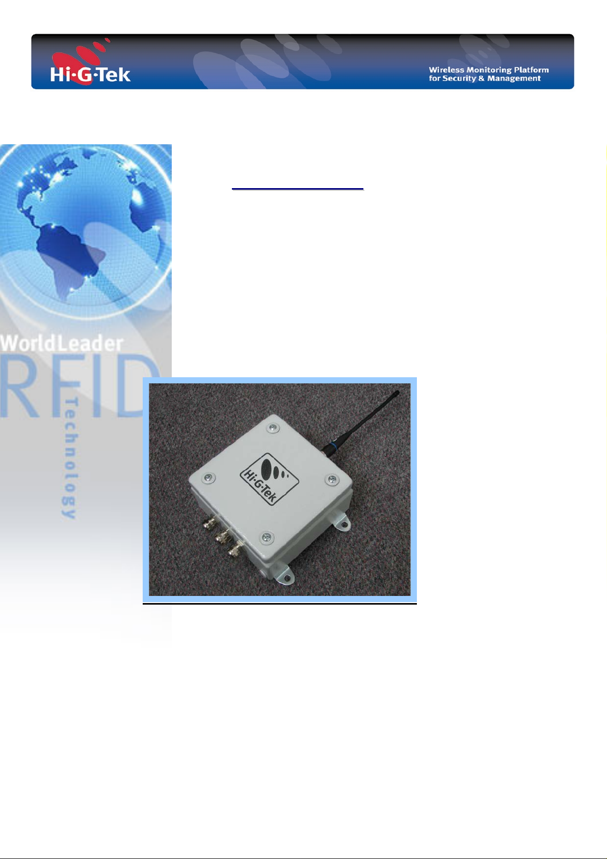
1. Introduction
The Compact Reader is a component of Hi-G-Tek’s wireless monitoring system use for
outdoor installations. It allows coverage and protection of secured cargoes or assets in
large storage yards and ports.
The Compact Reader utilizes RFID technology to communicate with the RFID sensors
(data tags /seals) over the UHF channel (433 MHz. or 916MHz). It interrogates their
ID, status and user data. Correspondingly, each tag/seal reports its unique identification
and anti-tamper alarm status in a short beacon transmission over the high-frequency
channel.
Each reader is able to communicate with a numerous sensors simultaneously, verifying
their presence and status, any changes in status are immediately reported. Using an
isolated RS-485 interface, multiple readers can be easily networked together into a
single controlling computer. This allows enlarging even further the coverage area of the
readers while keeping them synchronized within the field of application.
The Compact Reader powered from an indoor power supply & comm. unit (PSC unit)
that provides both protected power and isolated serial communication lines. Equipped
with RS-232 to RS-485 bi-directional serial communication converter, the PSC unit
easily forwards any RFID transaction from the Reader (RS-485) to the controlling
computer (RS-232) obtaining continually and real-time monitoring.
Page 2 of 7

2. Warnings and Cautions
• This device required to be connected to a certified power source 24VDC / 14W min..
• To avoid damaging, please follow the installation instructions.
ATTENTION
• Hi-G-Tek's Compact Reader is distributed to a commercial/industrial use only, and
should only be handled by personnel authorized by Hi-G-Tek representatives.
• Installation must be performed according to this User Guide.
• Using only certified antennas: It is the responsibility of the installer to ensure that
when using the outdoor antenna kits in the United States (or where FCC rules apply),
only those antennas certified with the product are used.
• The use of any antenna other than those certified with the product is expressly
forbidden in accordance with FCC rules CFR47 part 15.204 and part 15.203.
The FCC Wants You to Know
This equipment has been tested and found to comply with the limits for a Class B
digital device, pursuant to Part 15 of the FCC rules. These limits are designed to
provide reasonable protection against harmful interference in a residential installation.
This equipment generates, uses and can radiate radio frequency energy and, if not
installed and used in accordance with the instructions, may cause harmful interference
to radio communications. However, there is no guarantee that interference will not
occur in a particular installation.
If this equipment does cause harmful interference to radio or television reception,
which can be determined by turning the equipment off and on, the user is encouraged to
try to correct the interference by one or more of the
following measures:
a) Reorient or relocate the receiving antenna.
b) Increase the separation between the equipment and receiver.
c) Connect the equipment to an outlet on a circuit different from that to which the
receiver is connected.
d) Consult the dealer or an experienced radio/TV technician.
FCC Warning
Modifications not expressly approved by the manufacturer could void the user
authority to operate the equipment under FCC Rules.
Instructions concerning human exposure to radio frequency electromagnetic fields:
A distance of at least 20cm. between the equipment and all persons should be
maintained during the operation of the equipment.
Page 3 of 7

3. Installation Instructions
1. Unscrew the front panel screws and carefully dismantle
the top cover of the Compact Reader.
2. Insert power * and RS485 communication cable
(from PSC unit) through the left cable gland.
* 24VDC for IG-CR-46D-XXX, 48VDC for IG-CR-86D-XXX
3. Wire J1(screw-on terminal block) as shown figure1.3 (page.4)
4. Ensure cables are properly wired, tighten the cable glands
to obtain optimum sealing.
5. Connect the RS232 communication cable from the PSC unit
to the PC (COM port)
6. Switch on the external power supply, observe the Power indicator (on
the bottom side of the Reader) - the indicator flashes for approximately
5 seconds and remains illuminated.
Top cover screw
Cable Glands
Page 4 of 7

Figure 1.1: RS232 connection diagram
DB9 Female
Compact Reader
J10
9
2
3
5
9
8
7
1
Figure 1.2 : Power connection diagram
24VDC Power
Supply
J1
Compact Reader
8
-VIN
+VIN
1
Figure 1.3: Compact Reader - PSC Unit – RS485 Full duplex interconnection
Compact Reader - J1
PSC Unit
+VDC
Gnd
COMM
RxA
RxB
TxA
TxB
1
2
4
5
6
7
8
+VDC
1
Gnd
2
COMM
7
TxB
3
TxA
4
RxB
5
RxA
6
Page 5 of 7

Annex 1
J1 , J2
Compact Reader pinout
Compact Reader board
-Top view -
J10
DESCRIPTION PIN
+VIN 1
VIN- 2
SHIELD 3
SIGNAL GND 4
RxA (RS485) 5
RxB (RS485) 6
TxA (RS485) 7
TxB (RS485) 8
DESCRIPTION PIN
EXT. IN 1
GND 2
EXT.OUT1 3
EXT.OUT2 4
EXT.OUT3 5
OUTS-GND 6
RS232- GND 7
RS232-RXD 8
RS232-TXD 9
Page 6 of 7

Annex 2
Technical spec.
RF Characteristics
UHF Tx/Rx Channel
(Operating Frequency)
916.5 MHz or 433MHz (different models)
Range Up to 100m ( within open space)
Interfaces
Serial comm. RS232 for administration and isolated RS485
Antenna 50 ohm, whip (supplied)
I/O's Isolated 3 Outputs & 1 Input (active low)
Power Requirements
Power supply type: 24V or 48V powered from PSC Unit.
Power Consumption 1W Max
Physical Characteristics
Dimensions 150x150x80mm (5.9''x5.9"x 3.15" inch)
Weight 1580gr (3.4 Lb)
Environmental
Operating Temperature
-40°C to +70°C
Storage Temperature -40°C to +80°C
Protection Class. IP 65
Standards
FCC
(for 916 MHz models) part 15C, sub part B- class B, sub part C.
CE (for 433 MHz models) EMC /RADIO /SAFETY full compliance.
Safety cTUVus (pending) UL 60950-1 / CSA CS22.2 60950 -1
Models:
Compact Reader
IG-CR-46D-433 Power : 24VDC, Operating Freq: 433.92MHz
IG-CR-86D-433 Power : 48VDC, Operating Freq: 433.92MHz
IG-CR-46D-916 Power : 24VDC, Operating Freq: 916.5MHz
IG-CR-86D-916 Power : 48VDC, Operating Freq: 916.5MHz
PSC unit (Power supply & communication unit)
IG-PS-4RI Input: 100 ~ 240VAC, Output:24VDC, 14.4W
IG-PS-8RI Input: 100 ~ 240VAC, Output:48VDC, 14.4W
Page 7 of 7
 Loading...