

HIGOAL 2R Installation And Safety Manual

5
INSTALLATION AND SAFETY GUIDE
6
v022020
INSTALLATION AND SAFETY GUIDE
Before scanning make sure that the FB (central) button is white, if not reset
the panel, refer to page 6.
To activate the configuration mode, press the central button 3 times,
now the configuration mode is enabled for 10 minutes.
Download HIGOAL app from the app store and register.
Scan will be done when smartphone connected to a 2.4GHZ Wi-Fi.
Enable scan mode by long press FB button until the other
buttons blink in red and release, the panel is ready
to be scanned.
2R
Tip: short press on the FB button at any stage will restore the
panel to the initial state.
Open menu clicking the App logo, and select the first option "Scan".
Follow the instructions.
Latest panel added will be marked with a green frame.
Hot Tip: We recommend that you name the panel that was added and name
all the operation buttons on the panel.
Repeat the scan activity for the remaining smart panel installed in your home.
Now, all of the panels are connected with one another through the application.
Define functions according to your needs.
Extended explanation on HIGOAL website: https://higoal-group.com
To activate the configuration mode, press the central button 3 times, now the
configuration mode is enabled for 10 minutes.
Step 1
Reset
panel
Lock/Unlock
from panel
Lock/Unlock
from app
Restart
panel
Application:
After scanning all devices (Green FB), you now able to control them through the application.
The app allows to edit names and icons of devices, adding them to rooms, creating scenarios and
timers, sub-users, projects and more.
In HIGOAL website you will find tutorials about the usage of the app, for physical copy please
contact by email or phone.
Long press the FB (central)
button until all button light
green
Long press the FB (central)
button until it changes to blue
(4 seconds)
Press the Lock icon in the panel
page in the app to Lock/Unlock
Press 1st button and the FB
button, repeat 3 times.
Step 2 Step 3
The panel will turn off and
then buttons will light in
green, red, blue
FB (central) button changes
to blue and all buttons are off
Lock icon change state
accordingly to the state of
the panel
Wait a second between click to
1 FB 1 FB 1 FB
click
FB button will light in white –
Factory mode
Unlock – repeat step 1, the FB
will change to green
You able to lock from panel
and unlock form app and
oppsite
ALWAYS
SMARTER
Smart Operation System
2R
HIGOAL Group LTD.
www.higoal-group.com
2
3
4
INSTALLATION AND SAFETY GUIDE
Installation will be performed by a certified expert.
Disconnect main power before installation.
Wires connection will be done according the diagram
in the back of the panel.
C = Common power input
R1 = 1st output, 5amp
R2 = 2nd output, 5amp
+12 = 12v power supply, 0.5 amp
-12 = common power supply and dry contact
K1 = Dry contact for R1
K2 = Dry contact for R2
Maintain a steady, straight installation against
the wall.
Assembling panel's glass can be done in one
direction only.
Assembling the panel to the wall mount
(3/4 gang box) using the attached screws.
Shutter connection/Wiring A momentary button
requires changing the Dipswitch status.
A guide is attached to every smart panel.
R1
FB
R2
To use 2 dry contact
outputs as 110/220V,
bridge between C and L
In a plaster wall, install
a 3-gang wall mount
without butterfly screws.
K1 K2
12V
- +
2 dry contact
inputs for
outputs
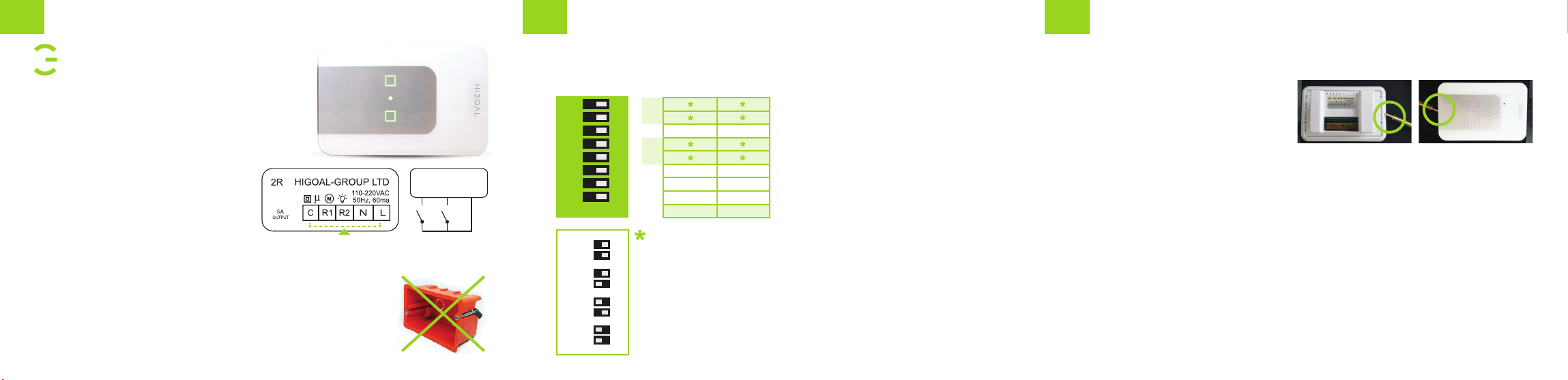
Dipswitch
Under the panel glass there is a dipswitch which used to configure (using the attached pin)
On-Off mode / Shutter mode / Shutter work time / Momentary mode / Safety mode. Configure
buttons before scanning.
8
7
6
5
4
3
2
1
ON/OFF
8
7
6
Timer On
5
4
3
Safety On
2
Timer On
1
Shutter mode
Timer Off
Safety Off
Timer Off
On-Off mode
OFFON
Dipswitches 7/8 – Output 2 work time
Dipswitch 6 – Output 2 timer On-Off
Dipswitches 4/5 – Output 1 work time
Dipswitch 3 – Output 1 Safety mode
Dipswitch 2 – Output 1 timer On-Off
Dipswitch 1 – Outputs 1/2 Shutter mode
Dipswitch
TIME 1
1 min
TIME 2
Momentary
TIME 3
3 mins
TIME 4
7 mins
5/8
4/7
5/8
4/7
5/8
4/7
5/8
4/7
4 Work times
for outputs
(Timer Mode,
Shutter)
1. Default work time for shutter mode is 1 min, in order to change
time, turn dipswitch 2 to On and set dipswitches 4/5
2. Dry contacts are parallel to buttons, for integrating 3rd party
systems, sensors and external switches
3. Built in 12v / 0.5amp power supply for external sensors
4. Setting timer mode to output is suitable with external sensor
connected by dry contact
5. Momentary mode – suitable with HIGOAL dimmer board
Operation Guide
After connecting and turn on the power, the button LEDs will turn on in blue, and the Central FB
button will turn on in White.
Disassembling the glass will be done using
a flat screwdriver in the left center of
the panel.
Assembling the glass after power on,
will be made when the panel is in locked mode.
20 seconds after assembling the glass you will be able unlock the panel, refer to page 6.
Button LEDs will decrease their intensity after 2 minutes, a short press on any button will increase
the intensity back.
Operation Buttons' LEDs color
Blue – channel off.
Green – channel On.
Light blue – Copy button.
Yellow – Scenario button.
Red – Momentary button.
FB button LEDs color
Blue – Panel locked.
Red – Network disconnected
Green – Network connected
White – Factory mode
Yellow – FW updated successfully
Download HIGOAL App from App store / Play store,
follow instructions and input all user details.
Scan each panel separately in order to connect it to
the Wi-Fi and App
 Loading...