

Highway Care BG800 Product And Installation Manual
ENGINEERING YOUR SAFETY
WWW.HIGHWAYCARE.COM
Rev. C – 10/18 ©2018 Highway Care Limited. All Rights Reserved.
Page 1 of 61
Product and Installation Manual
BG800
Australia & New Zealand
Temporary & Permanent Applications

ENGINEERING YOUR SAFETY
WWW.HIGHWAYCARE.COM
Rev. C – 10/18 ©2018 Highway Care Limited. All Rights Reserved.
Page 2 of 61
Revision History
Revision
Date
Prepared by
Approved by
Reason for change
A
Mar 2018
O. Pulling
P. Drinkwater
First issue - new branding.
B
June 2018
O. Pulling
P. Drinkwater
Minor updates – anchor
table.
C
October 2018
O. Pulling
P. Drinkwater
Calculated deflection MASH
standard addition
Contents
Introduction ........................................................ 4
Testing & Acceptance ..................................... 4
Characteristics................................................. 4
Design Considerations ....................................... 5
Median & Roadside Applications .................. 5
Length ............................................................... 5
Curves ............................................................... 5
Environment .................................................... 5
Slopes ............................................................... 5
Length of Need ................................................ 6
Ground Conditions ......................................... 6
Crash Cushions ................................................ 6
Anchoring ......................................................... 7
Delineators ...................................................... 7
Kerbs ................................................................. 7
Drainage ........................................................... 7
Weight .............................................................. 7
Safety Zone ...................................................... 8
Testing .............................................................. 8
System Types ...................................................... 9
Calculated Deflections ................................. 10
Standard – NCHRP 350 TL-3 ...................... 11
Standard – NCHRP 350 TL-4 ...................... 11
Standard – MASH TL-3 ............................... 12
Lower Deflection System (LDS) – NCHRP
350 TL-3 ....................................................... 12
Minimum Deflection System (MDS) –
NCHRP 350 TL-3 ......................................... 13
Minimum Deflection System (MDS) – MASH
TL-3 .............................................................. 14
Component Identification ............................... 15
Installation ........................................................ 16
Tools list ......................................................... 16
Preparation .................................................... 18
Getting Started .............................................. 18

ENGINEERING YOUR SAFETY
WWW.HIGHWAYCARE.COM
Rev. C – 10/18 ©2018 Highway Care Limited. All Rights Reserved.
Page 3 of 61
Safety Statements ......................................... 18
Lifting BG800 ................................................. 19
Using Tag Ropes ............................................ 20
Using Chains .................................................. 20
Ancillary Lifting Devices ............................... 21
Transport ....................................................... 22
Truck Mounted Cranes/Wheeled Excavator
......................................................................... 25
Terminal Installation .................................... 27
External Anchor Shoe ............................... 28
Standard Section Installation ...................... 29
Laying BG800 ................................................. 29
Joining BG800 Sections ................................. 30
Intermediate Anchoring ............................... 31
Single Sided Intermediate Anchors ............ 32
Different Anchor Types Installation ........... 34
Barrier Removal ............................................ 35
Noise Pollution .............................................. 35
Other Operations ............................................. 36
Curved Barrier ............................................... 36
Offset Ends to Barrier ................................... 39
Anti-Gawk Screen.......................................... 40
Mesh Fence .................................................... 40
Expansion Joints ............................................ 41
T-Top ............................................................... 42
Gate ................................................................ 43
Turning the Barrier Over ............................. 44
Inverting BG800 .......................................... 44
Righting Inverted BG800 ............................ 44
Maintenance & Repair ..................................... 45
Galvanising Durability .................................. 45
Photo Examples ................................................ 47
Frequently Asked Questions ........................... 50
Appendix ............................................................ 52
Foundation Pavement & Anchor Details ... 52
Anti-Gawk Screen Foundation Pavement &
Anchor Details ............................................... 53
Risk Assessments .......................................... 54
Installation Checklist Example .................... 57
Permanent Applications .............................. 59
Approvals ....................................................... 60
Contact Details.................................................. 61
ENGINEERING YOUR SAFETY
WWW.HIGHWAYCARE.COM
Rev. C – 10/18 ©2018 Highway Care Limited. All Rights Reserved.
Page 4 of 61
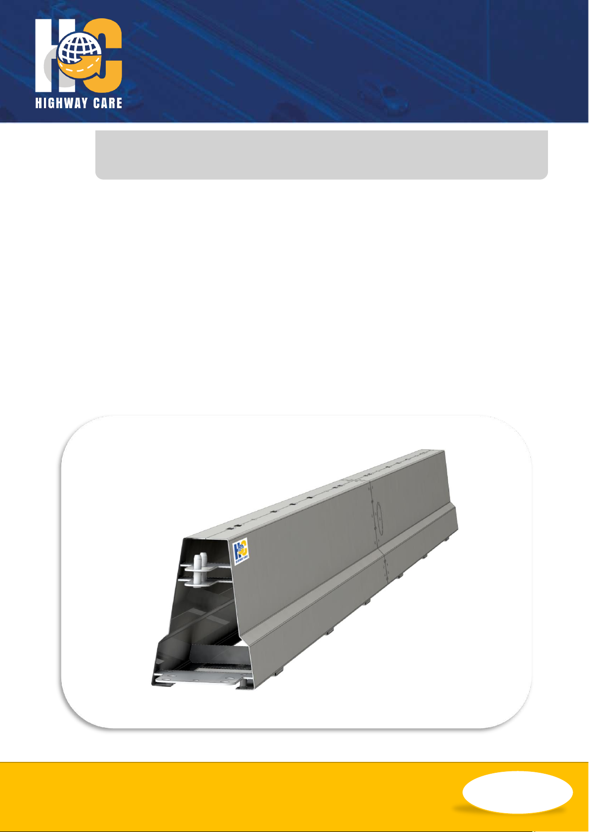
Introduction
BG800 is a versatile longitudinal steel barrier
vehicle restraint system that is anchored to the
ground at the ends of barrier runs. Standard
sections of BG800 are listed below;
• 6m & 12m standard sections
• 6m & 12m terminal end sections
BG800 has male and female QuickLink
connectors which allow for simple and speedy
connection when aligning two pieces of BG800,
and further shortens the installation times.
The BG800 can be utilised in permanent or
temporary applications and there are various
connections to other barrier systems and crash
cushions.
There is a standard system which is BG800 and
two main system variations. These are MDS
(Minimum deflection system) and LDS (Limited
deflection system).
Testing & Acceptance
BG800 has been developed as a rapidly
deployable Steel Safety Barrier for use where a
vehicle restraint system conforming to both
American & European test standards with a
selection of containment levels.
Characteristics
BG800 has been designed for both permanent
and temporary applications. Common uses
include;
• Work zone protection
• Contraflow opportunities
• Controlled access
• Bridge applications
Note: This manual is designed to complement any
project drawing packages that are provided. Where
conflicts arise the Highway Care project drawings
take priority over this manual.
ENGINEERING YOUR SAFETY
WWW.HIGHWAYCARE.COM
Rev. C – 10/18 ©2018 Highway Care Limited. All Rights Reserved.
Page 5 of 61
Design Considerations
Median & Roadside Applications
BG800 can be impacted from either side of the
barrier with no difference in performance.
Therefore, the barrier can be used in both
roadside and median/bi-directional traffic
applications.
Length
The permissible length of the system is
unlimited but the barrier must be anchored at
the end of each run and intermediately as
required by the system type.
The minimum recommended installed length of
BG800 is 18m between inner anchor shoes; i.e.
for an installation with no approved crash
cushion connected to the end terminal, the
minimum total system length including
terminals and anchors is 30m.
Note: Please refer to acceptance conditions which
may differ to the above recommendations.
Curves
Various degrees of movement can be achieved
using the following components.
• 0.67˚ at the QuickLink joint
• 5˚ at the 6m slotted plates joint
• 5˚ radius section
• 10˚ radius section
Examples of achievable curves can be found in
the Curved Barrier section of this manual.
Environment
BG800 should not be installed where there are
fixed objects that may affect performance of the
barrier if impacted.
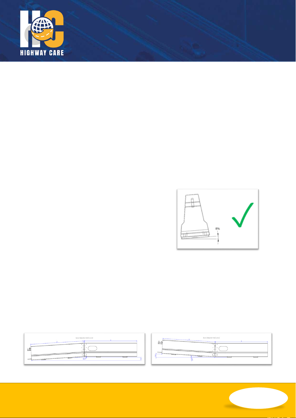
Slopes
For the system to perform correctly, it should be
installed on ground that has a cross slope of no
more than 8%. When installing the BG800 Gate
we recommend this maximum cross slope
should be reduced to 5% to allow controlled
manual operation of the gate.
Note: extreme care must be taken when opening a
gate on a slope as the gate can move under its own
weight.
The maximum incline and decline that BG800
can typically achieve is demonstrated in the
images below which shows a 6m section with
bolted slotted plates.

ENGINEERING YOUR SAFETY
WWW.HIGHWAYCARE.COM
Rev. C – 10/18 ©2018 Highway Care Limited. All Rights Reserved.
Page 6 of 61
Length of Need
The length of need for BG800 is the total
installed length between the two inner anchor
shoes.
The beginning of the length of need is measured
6m from the approach (upstream) end of the
BG800 terminal (at the inner anchor shoe). It
must be noted that when an approved, nongating (redirective) end termination such as a
crash cushion is connected to the BG800
terminal, then the approach (upstream) end of
such system becomes the beginning of the
length of need. If an approved, gating (nonredirective) end termination such as a crash
cushion is connected to the BG800 terminal,
then the beginning of the length of need
remains 6m from the approach (upstream) end
of the BG800 terminal (inner anchor point).
When deciding length of need of a system
consideration must be given to the proximity of
any anchor points to any excavations, if the
BG800 is to be used to protect errant vehicles
from excavations we recommend that the
anchoring takes place beyond any excavation
and if any extra anchoring is required, it should
be single sided away from the excavated face.
Ground Conditions
The ground conditions that the barrier is to be
installed on and anchored to, need to be
established to ensure the correct anchoring
choice is made and the appropriate anchor shoe
is connected to the barrier. Details of common
ground conditions and the available types of
anchors and anchor shoes can be found in
drawing BG-60-23 and in the appendix of this
manual.
Note: For use of BG800 on any ground conditions
or anchors that are not shown in this drawing
please contact Highway Care Ltd for further advice.
Crash Cushions
When choosing a suitable crash cushion for use
with BG800, special consideration must be given
to opting for a gating (non re-directive) crash
cushion or a non-gating (re-directive) crash
cushion. A non-gating crash cushion is one that
has been tested to withstand a side impact from
an errant vehicle and a gating system is one that
has not been tested for this impact angle. If
opting for a gating crash cushion then
consideration must be given to allow for a safe
run out area behind the system.
If it is not possible to locate the terminal ends
outside the clear zone, then an approved end
termination (such as a crash cushion) can be
fitted to the BG800 full height terminal. Any
crash cushion placed in front of a full height
terminal will have its own anchoring
specifications and assembly instructions. Any
connection between BG800 and the approved
end termination will be designed and supplied
by either the BG800 supplier or the approved
end termination supplier. They shall work
together to ensure a suitable connection is
available.
Approved end terminations that are currently
available with designed connections are:
I. Tau II – Non gating (re-directive)
II. QuadGuard – Non gating (re-directive)
III. Absorb 350 – Gating (non re-directive)
IV. TRACC – Non gating (re-directive)
V. SMART - – Non gating (re-directive)

ENGINEERING YOUR SAFETY
WWW.HIGHWAYCARE.COM
Rev. C – 10/18 ©2018 Highway Care Limited. All Rights Reserved.
Page 7 of 61
Anchoring
BG800 has successfully been tested with a
selection of anchoring methods and in various
ground conditions making it a versatile system
that can be used on many differing surfaces.
Standard BG800 requires anchoring to the
ground at each end of a run and at intermediate
locations spaced at 60m intervals. There are
integral anchor points beneath an easily
removed cover at the extreme end of the
specially designed anchor sections. There is a
second anchor point at the first bolted joint up
stream of the end of the section; these anchors
can either be external or internal anchor shoes
depending upon site restrictions or preference.
Both the anchor shoes and the integral anchor
points require 4 anchor pins/bolts each (8 in
total per end anchor section).
As a means of reducing the deflection of the
system, intermediate anchoring can be
introduced to create the BG800 Minimum
Deflection System (MDS) and Limited Deflection
System (LDS).
Delineators
Reflective delineators can be attached to the
side wall or top of the BG800 as required and at
the relevant spacing’s. There are two options of
delineators available, one a fixed reflector and
the second a reflector with a flexible joint which
helps makes it resistant to breaking.
In addition to the reflectors, there are available
specially manufactured brackets that allow cone
lamps to be fixed to the top of the BG800.
Other locally sourced options may also be
acceptable.
Kerbs
BG800 can be installed to a surface which is
raised by a kerb of no more than 100mm high.
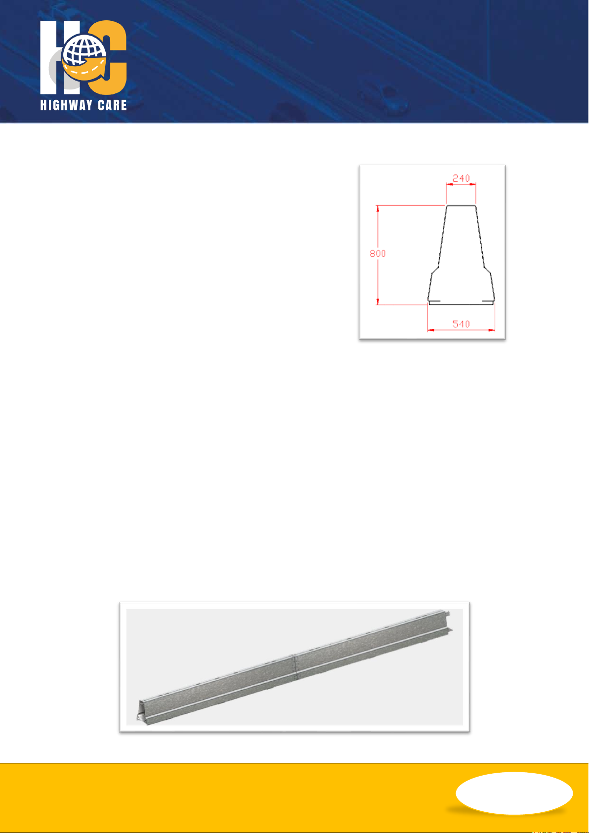
Drainage
The design of BG800 incorporates 250mm long
feet located at regular intervals along the barrier
that sit 30mm below the base of the lower side
wall and span the full width of the barrier. There
are three steel feet per 6m section.
Weight
BG800 weighs approximately 90kgs a metre.
Standard 12m sections have a nominal weight
of 1080kg and 6m sections nominally 540kg.
ENGINEERING YOUR SAFETY
WWW.HIGHWAYCARE.COM
Rev. C – 10/18 ©2018 Highway Care Limited. All Rights Reserved.
Page 8 of 61
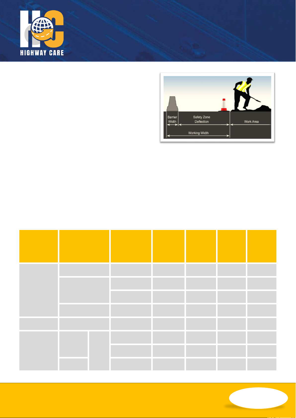
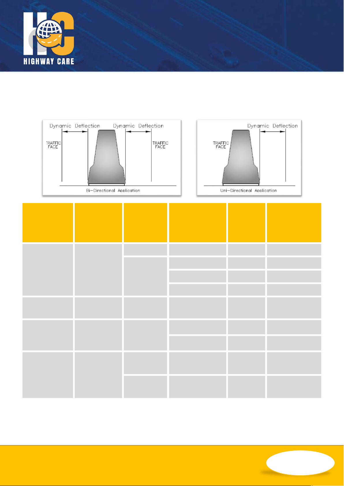
Safety Zone
BG800 systems require a safety zone behind
them to allow the system to perform correctly.
The safety zone size should meet or exceed the
dynamic deflection size listed in the System
Types section.
Testing
BG800 has been tested in accordance with NCHRP 350, MASH and BS EN 1317 parts 1 and 2 and has
successfully demonstrated its capability to achieve the following containment and performance levels.
NCHRP 350 TL-1, TL-2, TL-3 or TL-4, MASH TL-3 and BS EN 1317 Containment Level T1, T2, T3, N1, N2,
H1 or H2.
The design features of the BG800 enable it to be deployed as either a single or double sided barrier.
However, a factor to be taken into consideration when being utilised as a double-sided barrier, is the
working width (or deflection) of the system. The table below describes some of the test criteria met by
BG800.
Test
Standard
Performance
Level
Test
Reference
Vehicle
Type
Impact
Speed
(km/h)
Impact
Angle
(˚)
Vehicle
Mass
(kg)
NCHRP 350
Tl-2
2-11
Pickup
70
25
2000
TL-3
3-10
Light Car
100
20
820
3-11
Pickup
100
25
2000
TL-4
4-12
Truck
80
15
8000
MASH
TL-3
3-11
Pickup
100
25
2270
EN 1317
N2
L2
TB11
Light Car
100
20
900
TB32
Car
110
20
1500
H2
TB51
Bus
70
20
13000
ENGINEERING YOUR SAFETY
WWW.HIGHWAYCARE.COM
Rev. C – 10/18 ©2018 Highway Care Limited. All Rights Reserved.
Page 9 of 61
System Types
BG800 is a versatile product with many system variations to suite different project requirements. The
following section details various setup options.
System
Type
Anchor
Interval
(m)
Test
Standard
Performance
Level
Design
Speed
(km/h)
Dynamic
Deflection
(m)
Standard
60
MASH
TL-3
100
1.66
NCHRP 350
TL-4
80
1.74
TL-3
100
1.60
TL-2
70
1.36
Anti-Gawk
System (AGS)
36
NCHRP 350
TL-2 + 10 km/h
80
0.94
Lower
Deflection
System (LDS)
12
NCHRP 350
TL-4
80
0.42
TL-3
100
0.89
Minimum
Deflection
System (MDS)
6
NCHRP 350
TL-3
100
Top 0.305
Toe 0.076
MASH
TL-3
100
Top 0.470
Toe 0.130
Notes: MDS systems require the addition of T-Top sections along the top of the barrier. See T-Top section for
further details. Please refer to acceptance conditions which may differ to the above published deflections. AGS
system anchor spacing may be lower to ensure wind loading requirements are met.

ENGINEERING YOUR SAFETY
WWW.HIGHWAYCARE.COM
Rev. C – 10/18 ©2018 Highway Care Limited. All Rights Reserved.
Page 10 of 61
Calculated Deflections
Reduced safty zone data tables shows
calculated deflections in metres at various
performance levels for BG800 when anchored
as per system setup: (These calculations have
been based on actual test data).
The normalised deflections have been
calculated using the formula contained in the
extract from EN1317 part 2 UAP document
below.
Note: The actual and normalised values of dynamic
deflection and working width shall be measured
and recorded in the test report.
Normalised Dynamic Deflection: DN (m)
( )
( )
2
2
MMM
TTTM
N
SinVM
SinVMD
D
=
Normalised Working Width: WN (m)
NMMN
DDWW +−=
Where:
• Measured Maximum Dynamic Deflection: D
M
(m)
• Measured Working Width: W
M
(m)
• Test Total Mass: M
T
(kg)
• Test Velocity: V
T
(m/s)
• Test Angle: θ
T
• Measured Test Total Mass: M
M
(kg)
• Measured Test Velocity: V
M
(m/s)
• Measured Test Angle: θ
M
We can calculate the expected deflections of the
systems when impacted at slower speeds and
shallower impact angles using an EN1317
formula. These deflections are shown on the
systems pages in tables and can be used for
justifying reduced safety zones, when restricted
by site specific restraints.
ENGINEERING YOUR SAFETY
WWW.HIGHWAYCARE.COM
Rev. C – 10/18 ©2018 Highway Care Limited. All Rights Reserved.
Page 11 of 61
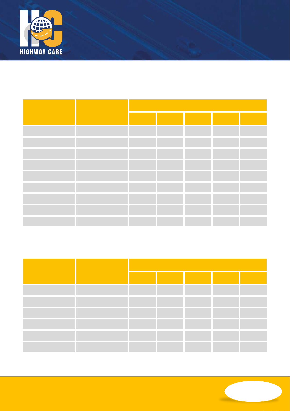
Standard – NCHRP 350 TL-3
Below is a table showing the expected deflections of the TL-3 BG800 system if impacted at various
angles and various speeds with a 2000kg Truck (60.0m Between Anchors).
Impact Speed
(mph)
Impact Speed
(km/h)
Deflection (m)
5˚
10˚
15˚
20˚
25˚
25
40
0.01
0.04
0.10
0.17
0.27
31
50
0.02
0.07
0.16
0.27
0.42
37
60
0.03
0.10
0.22
0.39
0.60
40
64
0.03
0.12
0.26
0.45
0.69
43
70
0.03
0.14
0.31
0.53
0.82
50
80
0.05
0.18
0.40
0.70
1.07
56
90
0.06
0.23
0.51
0.88
1.35
60
97
0.07
0.26
0.58
1.02
1.55
62
100
0.07
0.28
0.62
1.09
1.66
Standard – NCHRP 350 TL-4
Below is a table showing the expected deflections of the TL-4 BG800 system if impacted at various
angles and various speeds with an 8000kg Truck (60.0m Between Anchors).
Impact Speed
(mph)
Impact Speed
(km/h)
Deflection (m)
5˚
10˚
15˚
20˚
25˚
25
40
0.05
0.21
0.46 - -
31
50
0.08
0.32
0.71 - -
37
60
0.12
0.46
1.03 - -
40
64
0.13
0.53
1.18 - -
43
70
0.16
0.63
1.40 - -
50
80
0.21
0.82
1.82 - -
ENGINEERING YOUR SAFETY
WWW.HIGHWAYCARE.COM
Rev. C – 10/18 ©2018 Highway Care Limited. All Rights Reserved.
Page 12 of 61
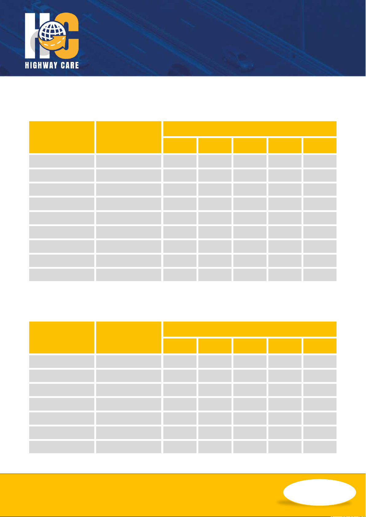
Standard – MASH TL-3
Below is a table showing the expected deflections of the TL-3 BG800 system if impacted at various
angles and various speeds with a 2270kg Truck (60.0m Between Anchors).
Impact Speed
(mph)
Impact Speed
(km/h)
Deflection (m)
5˚
10˚
15˚
20˚
25˚
25
40
0.01
0.04
0.10
0.17
0.26
31
50
0.02
0.07
0.15
0.26
0.40
37
60
0.02
0.10
0.22
0.38
0.58
40
64
0.03
0.11
0.22
0.44
0.67
43
70
0.03
0.13
0.25
0.52
0.79
50
80
0.04
0.17
0.30
0.68
1.03
56
90
0.06
0.22
0.39
0.86
1.31
60
97
0.06
0.25
0.49
0.99
1.51
62
100
0.07
0.27
0.56
1.06
1.61
Lower Deflection System (LDS) – NCHRP 350 TL-3
Below is a table showing the expected deflections of the LDS TL-3 BG800 system if impacted at various
angles and various speeds with a 2000kg Truck (12.0m Between Anchors).
Impact Speed
(mph)
Impact Speed
(km/h)
Deflection (m)
5˚
10˚
15˚
20˚
25˚
25
40
0.01
0.02
0.06
0.10
0.15
31
50
0.01
0.04
0.09
0.15
0.23
40
64
0.02
0.06
0.14
0.25
0.38
43
70
0.02
0.08
0.17
0.30
0.45
50
80
0.03
0.10
0.22
0.39
0.59
56
90
0.03
0.13
0.28
0.49
0.75
62
100
0.04
0.16
0.35
0.60
0.92

ENGINEERING YOUR SAFETY
WWW.HIGHWAYCARE.COM
Rev. C – 10/18 ©2018 Highway Care Limited. All Rights Reserved.
Page 13 of 61
Minimum Deflection System (MDS) – NCHRP 350 TL-3
Below is a table showing the expected deflections of the MDS TL-3 BG800 system if impacted at various
angles and various speeds with a 2000kg Truck (6.0m Between Anchors, with T-Top).
Impact Speed
(mph)
Impact Speed
(km/h)
Deflection at Top (m)
5˚
10˚
15˚
20˚
25˚
25
40
0.00
0.01
0.02
0.03
0.05
31
50
0.00
0.01
0.03
0.05
0.07
37
60
0.00
0.02
0.04
0.07
0.11
40
64
0.01
0.02
0.05
0.08
0.12
43
70
0.01
0.02
0.05
0.09
0.14
50
80
0.01
0.03
0.07
0.12
0.19
56
90
0.01
0.04
0.09
0.16
0.24
60
97
0.01
0.05
0.10
0.18
0.27
62
100
0.01
0.05
0.11
0.19
0.29
Impact Speed
(mph)
Impact Speed
(km/h)
Deflection at Toe (m)
5˚
10˚
15˚
20˚
25˚
25
40
0.00
0.00
0.00
0.01
0.01
31
50
0.00
0.00
0.01
0.01
0.02
37
60
0.00
0.00
0.01
0.02
0.03
40
64
0.00
0.01
0.01
0.02
0.03
43
70
0.00
0.01
0.01
0.02
0.04
50
80
0.00
0.01
0.02
0.03
0.05
56
90
0.00
0.01
0.02
0.04
0.06
60
97
0.00
0.01
0.03
0.04
0.07
62
100
0.00
0.01
0.03
0.05
0.07

ENGINEERING YOUR SAFETY
WWW.HIGHWAYCARE.COM
Rev. C – 10/18 ©2018 Highway Care Limited. All Rights Reserved.
Page 14 of 61
Minimum Deflection System (MDS) – MASH TL-3
Below is a table showing the expected deflections of the MDS TL-3 BG800 system if impacted at various
angles and various speeds with a 2270kg Truck (6.0m Between Anchors, with T-Top).
Impact Speed
(mph)
Impact Speed
(km/h)
Deflection at Top (m)
5˚
10˚
15˚
20˚
25˚
25
40
0.00
0.01
0.03
0.05
0.07
31
50
0.00
0.02
0.04
0.08
0.11
37
60
0.01
0.03
0.06
0.11
0.17
40
64
0.01
0.03
0.07
0.12
0.19
43
70
0.01
0.04
0.08
0.15
0.22
50
80
0.01
0.05
0.11
0.19
0.29
56
90
0.02
0.06
0.14
0.24
0.37
60
97
0.02
0.07
0.16
0.28
0.43
62
100
0.02
0.08
0.17
0.30
0.46
Impact Speed
(mph)
Impact Speed
(km/h)
Deflection at Toe (m)
5˚
10˚
15˚
20˚
25˚
25
40
0.00
0.00
0.01
0.01
0.02
31
50
0.00
0.01
0.01
0.02
0.03
37
60
0.00
0.01
0.02
0.03
0.05
40
64
0.00
0.01
0.02
0.03
0.05
43
70
0.00
0.01
0.02
0.04
0.06
50
80
0.00
0.01
0.03
0.05
0.08
56
90
0.01
0.02
0.04
0.07
0.10
60
97
0.01
0.02
0.04
0.08
0.12
62
100
0.01
0.02
0.05
0.08
0.13
ENGINEERING YOUR SAFETY
WWW.HIGHWAYCARE.COM
Rev. C – 10/18 ©2018 Highway Care Limited. All Rights Reserved.
Page 15 of 61
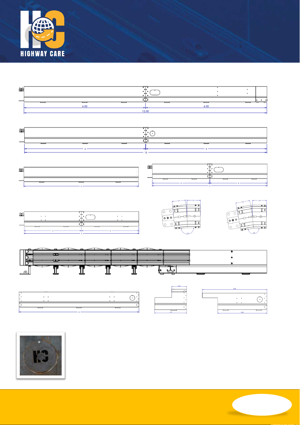
Component Identification
12m full height terminal - male/female QuickLink
12m standard – male/female QuickLink
6m single piece – male/female QuickLink 6m standard section with 5˚ slotted plates at join
6m wheelset – male/female QuickLink 5 degree, 10 degree angle sections – left/right
Crash cushion end treatment
6m gate section 1.4m gate post 3m gate hinge
Notes: All M16 bolts used for connecting sections of BG800 together to be at least grade
8.8. Numerous extra components are available and bespoke options also. Please
contact Highway Care for further information.
Future Highway Care manufactured and supplied barrier is identifiable with the
Highway Care logo on the access hatch plate.

ENGINEERING YOUR SAFETY
WWW.HIGHWAYCARE.COM
Rev. C – 10/18 ©2018 Highway Care Limited. All Rights Reserved.
Page 16 of 61
Installation
Tools list
Tool
Information
Lifting Device
Such as lorry mounted crane or wheeled excavator. Must have suitable lifting
capacity and reach to lift, manoeuvre and install BG800. It is also
recommended that these cranes are remote control for ease of use.
Lifting Chains
A two leg assembly with a 2500kg lifting capacity, each chain is 2m long c/w
hook and locking clasp, and shortening clutch. This is suitable for lifting
12m sections of barrier and 6m sections made up from 2 x 3m sections
only.
A two leg set with a 2500kg lifting capacity, each chain needs to be 3m long
c/w hook and locking clasp, and shortening clutch. These chains are for
lifting 6m lengths of barrier that are half of the 12m sections.
Tag Rope
Rope with spring loaded carabineer clip. The rope length needs to be 1.5
times the lifting height of the barrier.
Drilling Equipment
Either an electric hammer drill c/w 32mm drill bit or an air driven rock drill
c/w 33mm rock drill tool. To speed up installation consideration should be
given to having 2 drilling machines available.
Also, a diamond core drill suitable for cutting a 32mm hole up to 300mm
deep in case of reinforcement bar when drilling in concrete.
Generator &
Extension Lead
For use with the hammer drills, and/or diamond core drill. Should be capable
of a high enough output to drive two hammer drills at the same time as a
minimum.
Measuring Wheel &
Road Marking
Paint/chalk
To mark BG800 positioning where required.
2 off 6ft crow
bar/wrecking bar
To assist with minor barrier re-alignment.
10m Measuring
Tape,

ENGINEERING YOUR SAFETY
WWW.HIGHWAYCARE.COM
Rev. C – 10/18 ©2018 Highway Care Limited. All Rights Reserved.
Page 17 of 61
8mm & 10mm Allen
Keys
Magnetic BG800 ‘T’
Bar Socket
For inserting and removing QuickLink security nut.
Wooden Packers
Approx. 520mm x 300mm x 19mm. wooden ply wood packers. These are
used to support barrier over uneven surfaces.
Timbers
Two blocks approximately 200mm x 200mm x 300mm.
Approximately 75mm x 75mm timber bearers.
Small Impact Gun
Complete with suitable sockets. 24mm impact socket as a minimum.
Compressor &
Extension Pipes
For the Rock Drills and Impact Gun. Should be capable of driving two rock
drills at once.
Spanners/Wrenches
Combination spanners to include as a minimum 2 of each of the following
13mm, 24mm, 30mm, 32mm & 36mm.
½ & ¾ Drive Socket
Sets
Torque Wrench (S)
Suitable for torques up to 150 Nm. C/W suitable 24mm socket.
Torque Wrench (L)
Suitable of torques up to 300 Nm. C/W suitable 32mm socket
Podger (round pry
bar)
Sledge Hammer
To hammer in anchor pins.
Cranked Crow Bar
Useful for removing tight pins.

ENGINEERING YOUR SAFETY
WWW.HIGHWAYCARE.COM
Rev. C – 10/18 ©2018 Highway Care Limited. All Rights Reserved.
Page 18 of 61
Preparation
Before any installation is carried out, it is
important to prepare and plan correctly. This
may involve planning barrier positions using
CAD layouts and/or performing site visits. This is
necessary to keep time spent on site to a
minimum and ensure the installation proceeds
without issues. Items to be considered and
checked are; lifting restrictions such as low
bridges/overhead cables, underground services
in the vicinity of drilling operations, layout and
alignment of barrier.
Getting Started
When planning the job, it is essential that the
following points are established and agreed
with the client:
• The required performance level of the
BG800.
• The start, finish and alignment of the BG800.
• Any additional anchorages required (e.g. to
reduce deflection at a specific hazard that
cannot be relocated away from the safety
zone) and their locations.
• Any curvature of the BG800 in both the
horizontal and vertical planes.
• The type of pavement construction and the
method of anchorage.
• Any expansion joints are identified.
• In the case of concrete pavements, if
reinforcement is encountered when drilling
that this can be drilled through.
• The method of reinstatement of drilled holes
when the BG800 is removed.
• There are no underground services,
waterproof membranes etc. Which could be
damaged by drilling.
• There are no overhead cables that could be
contacted by the lifting operation.
• There is adequate working room and safety
zone.
Safety Statements
General Safety
• All required traffic safety precautions should
be complied with. All workers should wear
required safety clothing. (Examples, and not
limited to, include: high visibility vests, steel
capped footwear, gloves).
• Only authorised trained personnel should
operate any machinery. Where overhead
machinery is used, care must be taken to
avoid any overhead hazards.
• Before drilling or excavation always ensure
that the area is clear of underground
services. (The appropriate service providers
may need to be contacted).
• Avoid placing hands or fingers in and around
moving machine parts when components
are being lifted and manoeuvred into place.
System Safety Statements
• Take care when unloading the BG800
components as there may be limited space
to work with. Never go underneath a load
that is being lifted.
• All operatives must be careful when
installing BG800 especially with the risk of a
trapping injury occurring.
ENGINEERING YOUR SAFETY
WWW.HIGHWAYCARE.COM
Rev. C – 10/18 ©2018 Highway Care Limited. All Rights Reserved.
Page 19 of 61
Lifting BG800
Each standard 12m section of BG800 weighs
approximately 1080kg.
If using the normal method of installation with a
lorry mounted crane and articulated truck, the
safe working load of the crane must be in excess
of 1.08 tonnes at a reach of 8m to enable 12m
units to be safely offloaded, loaded and installed
on site.
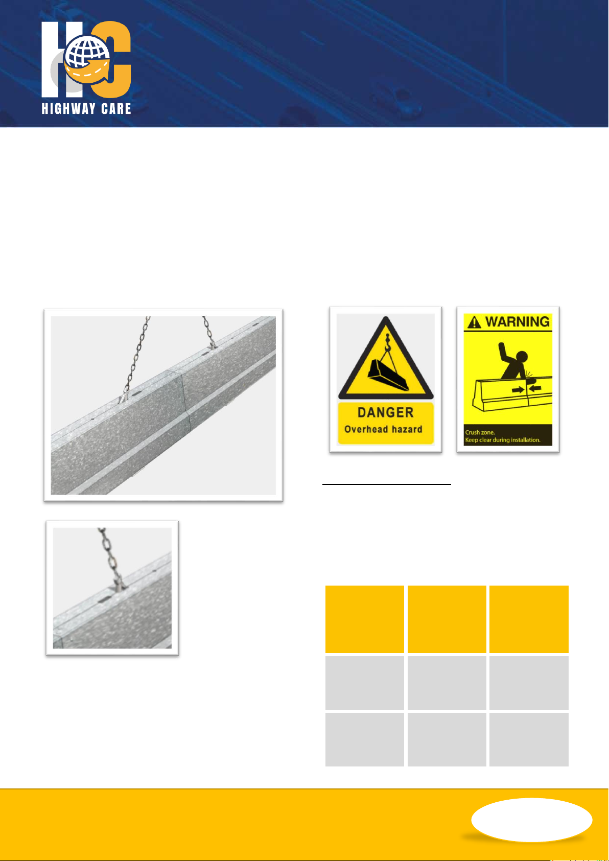
BG800 is lifted
with two leg
chains attached
to the lifting
points on the top
of the barrier.
Each individual
piece of BG800
has two lifting
points and when these pieces are bolted
together to make up a normal section of BG800,
there are four possible lifting points along its
length. BG800 has identical lifting points on the
underside to facilitate lifting inverted sections.
If the barrier to be lifted has a bolted joint in its
length (I.E. A section made from two pieces)
then using the standard chains, the barrier must
be lifted from the lifting points closest to and
either side of this bolted joint. If the length of
barrier is a piece without a joint in the middle
(I.E. an individual piece) then the longer chains
are required as the lifting points are at either
end of the piece.
Lifting Point Certification
Each lifting point has been welded in
accordance with DIN 18800 class E. Two lifting
points per barrier should be used. Below is the
capacity table that each lifting point has been
designed and engineered to.
Item
Max
Weight
(kg)
Lifting
Capacity
6m Section
Male: 562
Female 555
4.1 times the
weight of 6m
Section.
12m Section
1155
2.0 times the
weight of
12m Section
 Loading...