

Highway Care BarrierGuard 800 Product And Installation Manual
ENGINEERING YOUR SAFETY
WWW.HIGHWAYCARE.COM
Rev. A – 06/17 © 2018 Highway Care Limited. All Rights Reserved.
Page 1 of 23
Product and Installation Manual
BarrierGuard 800 Gate
NCHRP 350 TL-3
Australia & New Zealand

ENGINEERING YOUR SAFETY
WWW.HIGHWAYCARE.COM
Rev. A – 06/17 © 2018 Highway Care Limited. All Rights Reserved.
Page 2 of 23
Revision History
Revision
Date
Prepared by
Approved by
Reason for change
A
June 2017
O. Pulling
W. Duckworth
New branding - first issue.
Contents
Introduction ........................................................ 3
Testing & Acceptance ..................................... 3
Characteristics................................................. 3
Design Considerations ....................................... 4
Median and Roadside Applications .............. 4
Connection ....................................................... 4
Environment .................................................... 4
Gate Length ..................................................... 4
Anchoring Options .......................................... 5
Deflections ....................................................... 5
Standard Opening Options ............................... 6
Component Identification ................................. 7
Safety Statements .............................................. 8
Installation Instructions .................................... 9
Preparation ...................................................... 9
Tools & Equipment.......................................... 9
Installation......................................................... 10
Step 01 – Measuring ..................................... 10
Step 02 – Assembly ....................................... 10
Step 03 –Position ........................................... 11
Step 04 – Connection .................................... 11
Step 05 – T-Top .............................................. 11
Step 06 – Anchor ........................................... 12
Step 07 – System Check ................................ 12
Operation .......................................................... 13
Maintenance & Repair ..................................... 14
Photo Examples ................................................ 15
Frequently Asked Questions ........................... 16
Appendix ............................................................ 18
Foundation Details ....................................... 18
Anchor Installation Detail ............................ 20
Resin Anchor Studding ............................. 20
Mechanical Anchor Bolt ........................... 20
Installation Checklist Example .................... 21
Approvals ........................................................... 22
Contact Details.................................................. 23
ENGINEERING YOUR SAFETY
WWW.HIGHWAYCARE.COM
Rev. A – 06/17 © 2018 Highway Care Limited. All Rights Reserved.
Page 3 of 23
Introduction
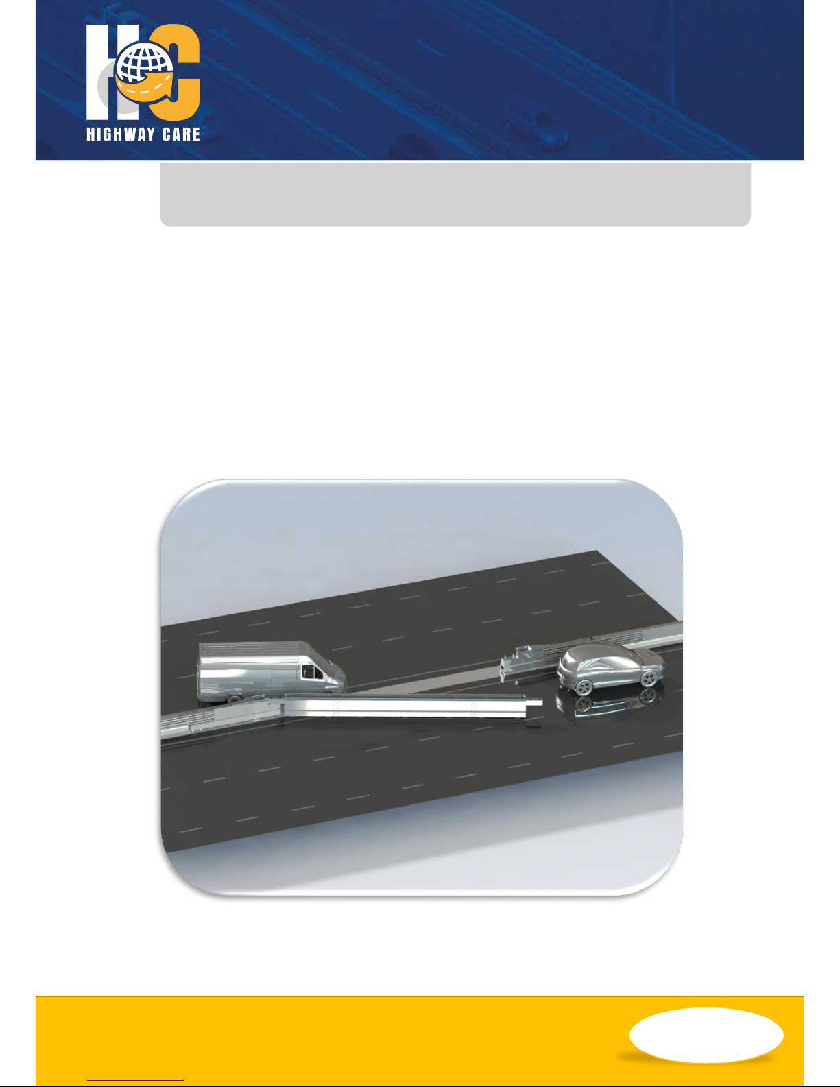
The BarrierGuard 800 Gate is a modular system
that is made up from special sections of
BarrierGuard 800, these are listed below;
• Gate post sections
• Gate hinge sections
• Gate sections
The BarrierGuard 800 Gate can be utilised as a
permanent or temporary application and
installed directly into a run of BarrierGuard 800
or by utilising one of the connection pieces can
be used as a stand-alone system attached to
various safety barriers & fences including, but
not limited to; concrete and thrie beam to wbeam.
Testing & Acceptance
The BarrierGuard 800 Gate system has been
designed and tested to meet the evaluation
criteria of NCHRP 350 Test Level 3 (TL-3) and has
been given eligibility by the Federal Highways
Administration (FHWA). It is approved for use in
USA, Australia and many more countries.
BarrierGuard 800 Gate smoothly redirects a
vehicle during an impact that meets the test
parameters of NCHRP 350.
Characteristics
BarrierGuard 800 Gate has been designed for
both permanent or temporary applications and
acts as a longitudinal barrier when closed.
Common uses include;
• Emergency vehicle access
• Work zone access
• Contraflow opportunities
• Controlled access point
Note: This manual is designed to complement the
gate drawing package provided. Where Highway
Care bespoke gates are designed the project
drawings take priority over this manual.
ENGINEERING YOUR SAFETY
WWW.HIGHWAYCARE.COM
Rev. A – 06/17 © 2018 Highway Care Limited. All Rights Reserved.
Page 4 of 23
Design Considerations
Median and Roadside
Applications
The BarrierGuard 800 Gate can be impacted
from either side of the barrier with no difference
in performance levels. Therefore, the barrier
can be used in both median and road side
situations in either orientation; as long as the
site condition has sufficient space and suitable
ground conditions.
Connection
Connections from the BarrierGuard 800 Gate to
other types of barriers are possible (thrie beam,
w-beam, concrete and BarrierGuard 800).
Examples are below. Additional connections are
available; please contact Highway Care for
further details.
Connection to precast or slip form concrete
Connection to BarrierGuard 800
As the gate is anchored at the full height
terminal/gate post no strength is required from
adjoining barrier for the system performance.
Environment
BarrierGuard 800 Gate should not be installed
where there are ditches or kerbs that may affect
operation of the gate. It is recommended that
the gate is installed on straight sections but
slight curves can be accommodated.
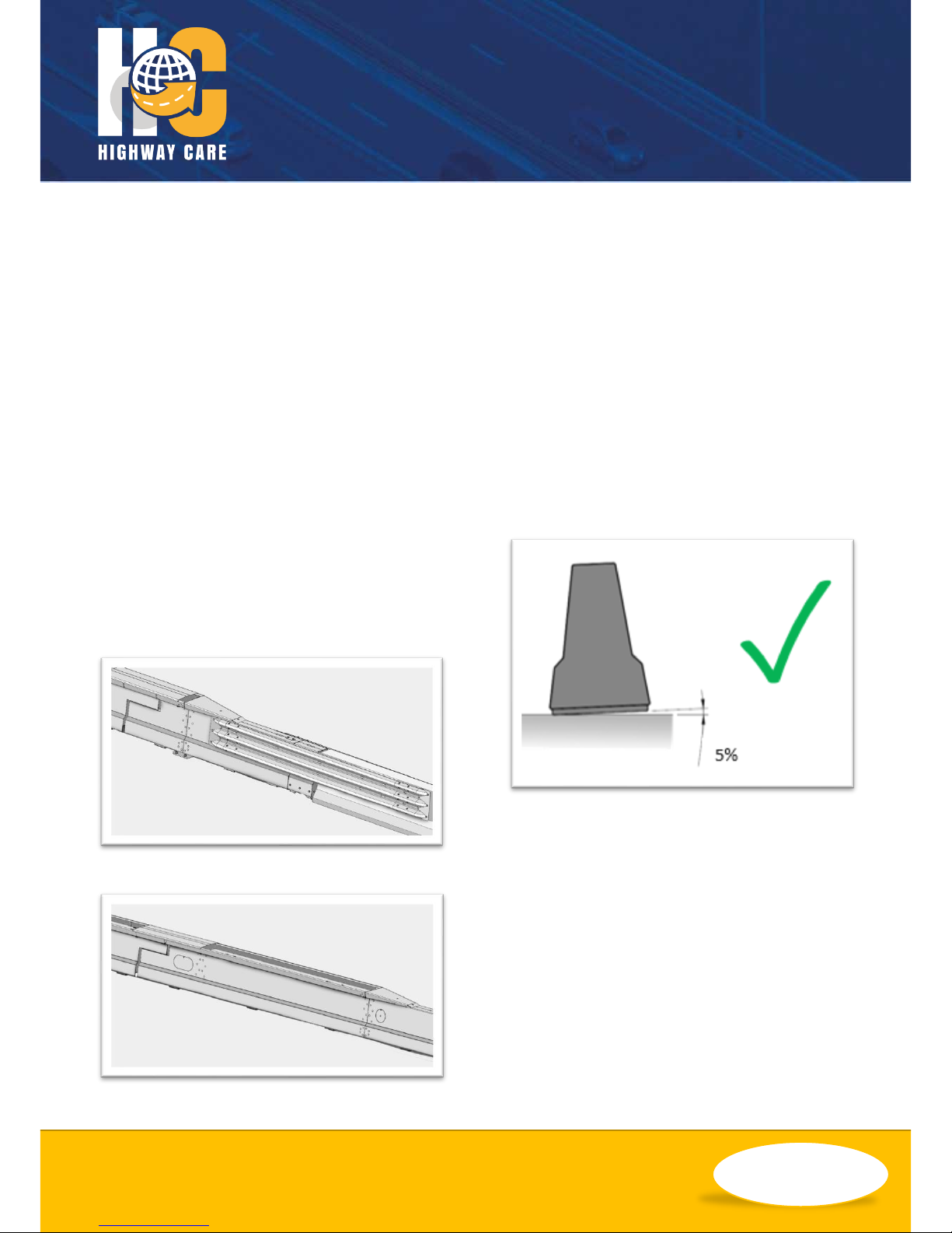
The BarrierGuard 800 Gate works on slopes, but
it is recommended that the cross fall does not
exceed 5% to allow controlled manual
operation.
Note: Care must be taken when opening the gate
on a slope as the gate can move by itself when
detached from both hinges with the wheels down.
Gate Length
Standard gate lengths are 6m, 12m, 18m, 24m,
30m and 36m. These gate sizes provide
openings of 4.67m, 10.67m, 16.67m, 22.67m,
28.67m and 34.67m respectively.
Please contact Highway Care for bespoke sizing
options.

ENGINEERING YOUR SAFETY
WWW.HIGHWAYCARE.COM
Rev. A – 06/17 © 2018 Highway Care Limited. All Rights Reserved.
Page 5 of 23
Anchoring Options
The BarrierGuard 800 Gate requires anchoring
with sufficient strength from the supporting
ground conditions, to allow the gate to perform
as tested. The appendix contains further details
for foundation options.
Deflections
Deflection measurements from actual crash
testing provides a setting that can be useful
when assessing a products suitability to
perform at a given location.
Tested Parameters
Test
Standard
Performance
Level
Test
Reference
Vehicle
Type
Impact
Speed
(km/h)
Impact
Angle
(˚)
Vehicle
Mass
(kg)
NCHRP 350
TL-3
3-21
Pickup
100
25
2000
Test Result
Dynamic Deflection
1.16m
ENGINEERING YOUR SAFETY
WWW.HIGHWAYCARE.COM
Rev. A – 06/17 © 2018 Highway Care Limited. All Rights Reserved.
Page 6 of 23
Standard Opening Options
ENGINEERING YOUR SAFETY
WWW.HIGHWAYCARE.COM
Rev. A – 06/17 © 2018 Highway Care Limited. All Rights Reserved.
Page 7 of 23
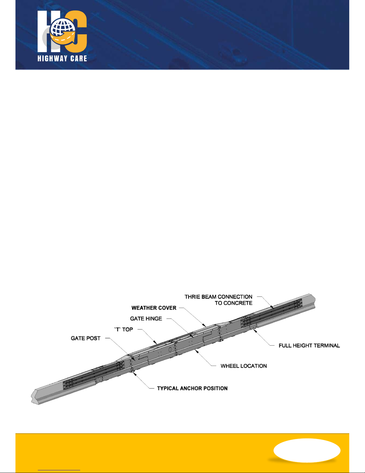
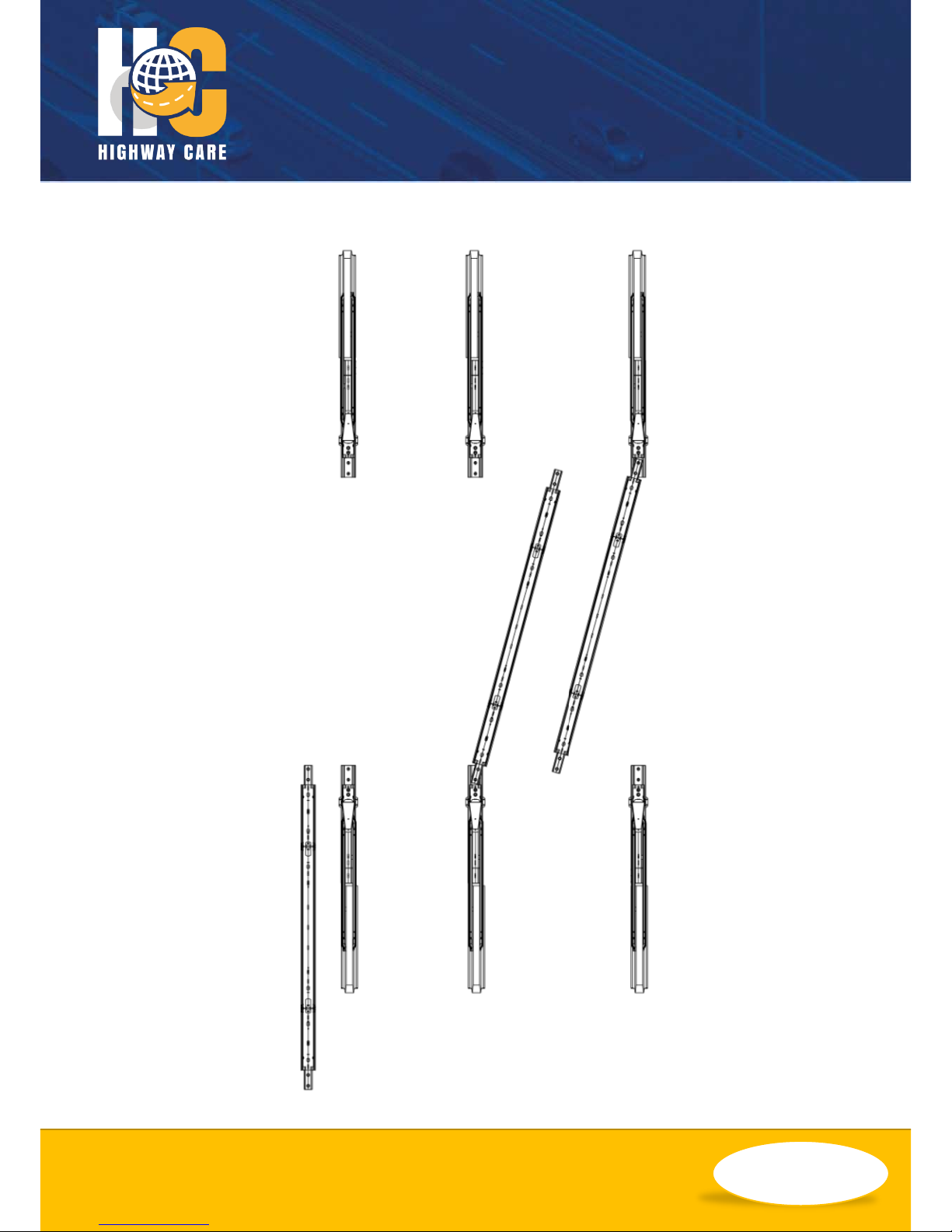
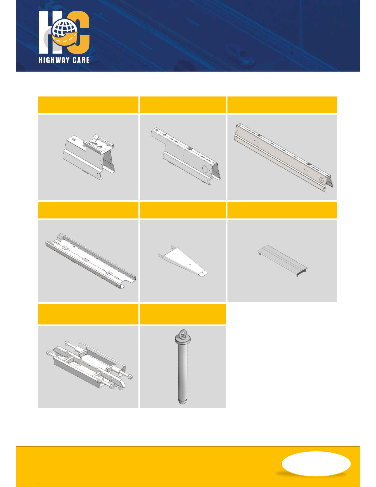
Component Identification
Fixed Gate Post
Mobile Hinge
Gate Section
T-Top
T-Top Transition
Weather Cover
Removable T-Top Section &
Fittings
Gate Pin
 Loading...