

Page 1

EQ-6S
6-BAND STEREO EQUALIZER
USER GUIDE
HIGHgVOLTAGE
A U D I O
WWW.HIGHVOLTAGEAUDIO.NET
Page 2

!
F CAUTION: HIGHgVOLTAGE !
RISK OF ELECTRIC SHOCK
!! WARNING !!
SET AC VOLTAGE SELECTION INSIDE BEFORE USE
HEALTH AND SAFETY
- Always read these complete instructions before operating the equipment.
- Always use a properly grounded IEC cable with this equipment and never defeat the
grounding pin as this provides not only a safety ground but is required for low noise
operation.
- Avoid using this equipment around stray magnetic fields. The enclosure is designed to
shield the circuits from magnetic fields and radio interference and so during racking of
the equipment it’s important to ensure typical grounding procedures are followed.
- Avoid the use of the equipment in high temperature environments as this can degrade
the performance and reduce the lifetime of the internal components.
- There are some internally accessible adjustments in this equipment. If there is a
requirement to perform internal adjustments, please ensure one is comfortable with
opening the equipment and performing said adjustments. Please seek qualified
assistance if unsure.
- If adjustments are to be made to this equipment, please disconnect the equipment from
mains power prior to opening the equipment and performing the adjustment. While we
understand that some adjustments are to be made with the equipment live, any damage
to the equipment as a result of dropped metal objects or liquid damage will not be covered
by the warranty.
HIGH VOLTAGE AUDIO reserves the right to change the specifications or modify the designs of
its equipment. Company contact information is on the last page of this manual.
VOLTAGE SELECTION AND FUSE
This equipment is capable of operating over a range of mains voltages to cater for various
regions. Please ensure the correct mains voltage setting and correct fuse are used prior to
connecting the equipment to mains. To avoid the risk of fire, replace the mains fuse only with
the correct value.
For mains voltages from 100-120 VAC, use a T200mAL (M205 SLO-BLO only) and configure the
internal mains voltage selector to display 115V. For mains voltages from 200-240 VAC, use a
T100mAL (M205 SLO-BLO only) and configure the internal mains voltage selector to display
230V.
Page 3

| 3
THANK YOU FOR CHOOSING
HIGHgVOLTAGE
A U D I O
Thank you for choosing products from HIGH VOLTAGE AUDIO. We expect you will be satisfied
with the quality, performance and value of our products, which are made possible through careful
design and construction choices.
ABOUT HIGH VOLTAGE AUDIO
HIGH VOLTAGE AUDIO is a partnership based in Australia, working out of both Melbourne and
Perth. We go to every effort to accurately create the tone, feel and functionality of great outboard
gear. Our work is the culmination of years of experience in sound production and electronics.
Our products are built here in Australia, so our customers can have the confidence that they will
purchase a product that not only sounds great, but is dependable, reliable and easy to use.
In 2017, we shipped our acclaimed bus compressors all over Australia, and all over the globe.
In 2018, we are proud to begin the year by launching our first equalizer product offering, in the
form of the HIGH VOLTAGE AUDIO EQ-6S - a mastering grade six (6) band stereo equalizer.
Page 4
!
OVERVIEW
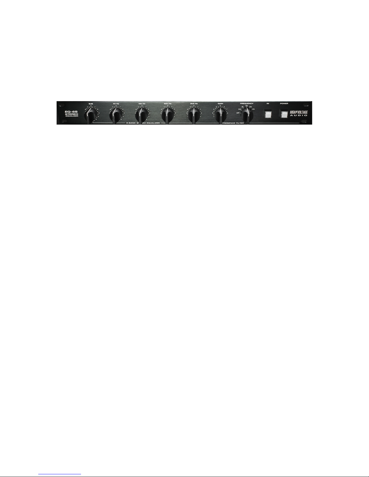
The HIGH VOLTAGE AUDIO EQ-6S is a six (6) band, mastering grade stereo equalizer. With its
precision built stepped rotary switches, at 0.5 dB steps for a total +/- 5.5 dB range, the EQ-6S
provides perfect stereo tracking and ease of recall.
The EQ-6S equalizer is a broad-stroke, sound sculpting device with five (5) fixed frequency bands
and a frequency switchable, high shelf PRESENCE FILTER.
Unlike the majority of equalizers on the market, the EQ-6S is a dedicated stereo equalizer. With
one set of controls under the hood, the EQ-6S is incredibly quick and easy to dial in.
Compared to its rivals, the EQ-6S boasts unrivaled control, precision, noise performance and
value. The EQ-6S is capable of broad, colourful EQ sculpting, perfect for adding character as well
as high end sparkle to mixes.
LETS GET TECHNICAL
Each of the EQ-6S filter bands are built around non-inverting gain stages sitting between 6
dB/Octave high and low pass filters. The filters are designed to be four times the previous band
and the signal exits the previous band at a drop of -6 dB. The signal then flows into the following
stage to add back up to 0 dB.
Since non-inverting gain stages have a positive voltage gain, the EQ-6S’s bands all interact with
one another to an extent. When increasing the gain of the
PRESENCE FILTER
, there will be an
overall increase in gain across the whole frequency response.
Page 5
| 5
REAR PANEL CONNECTIONS
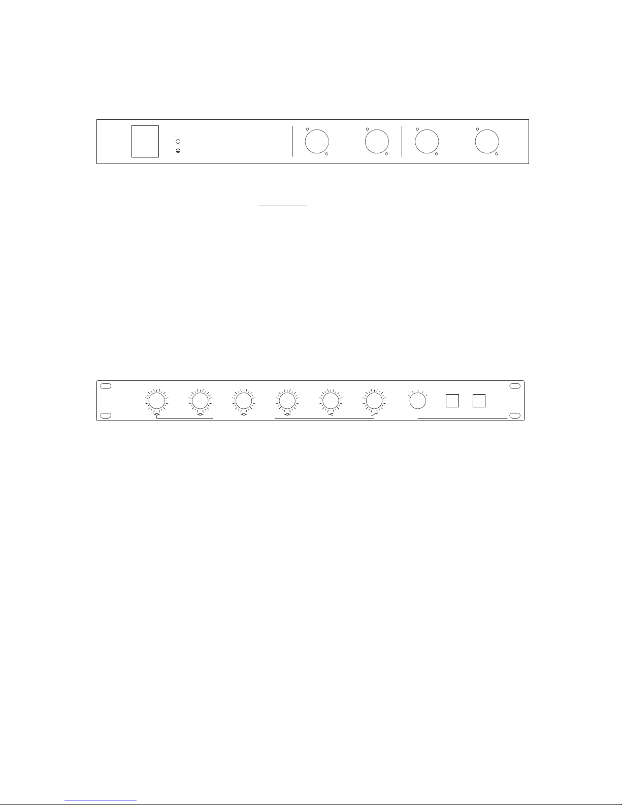
The rear panel features XLR INPUT and OUTPUT connectors for the LEFT and RIGHT channels.
These connections have been wired PIN 2 HOT to conform with AES standards.
NOTE: To run in unbalanced mode, ensure your unbalanced cable ties pin 3 to pin 1 at the cable.
The AC INPUT connection is a typical 3 pin IEC power cable. You must use the correct fuse value
and ensure the internal voltage selector meets the requirements for your region.
PLEASE REFER TO THE VOLTAGE SELECTION AND FUSE SECTION ON PAGE 2 PRIOR TO
POWERING YOUR UNIT.
front PANEL CONTROLS
The front panel features five (5) fixed frequency controls for each band. A separate
PRESENCE
FILTER
control, consisting of an additive-only gain control and a six (6) step frequency selector.
The IN illuminated push button, when pushed in, will engage both channels simultaneously.
When this push button is out and non-illuminated, both channels will be disengaged and will
perform a true bypass of the equipment.
The
POWER
illuminated push button, when pushed in, will power the unit ready for use. When
this push button is out and non-illuminated, the equipment is in a powered down state.
RIGHT CHANNEL
LEFT CHANNEL
OUTPUT OUTPUT
INPUT
INPUT
AC INPUT
F
CAUTION: HIGHgVOLTAGE
!
RISK OF ELECTRIC SHOCK
!! WARNING !!
SET AC VOLTAGE SELECTION INSIDE BEFORE USE
40 Hz
160 Hz
2k5 Hz
IN
POWER
650 Hz
FREQUENCY
GAIN
EQ-6S
STEREO
EQUALIZER
6-BAND STEREO EQUALIZER
HIGHgVOLTAGE
A U D I O
SUB
PRESENCE FILTER
-5
-3
0
-2
-1
-4
5
3
2
1
4
OFF
10k
2k55k40k
20k
Hz
-5
-3
0
-2
-1
-4
5
3
2
1
4
-5
-3
0
-2
-1
-4
5
3
2
1
4
-5
-3
0
-2
-1
-4
5
3
2
1
4
-5
-3
0
-2
-1
-4
5
3
2
1
4
0
2
5
3
4
1
10
8
7
6
9
Page 6
!
frequency BANDS
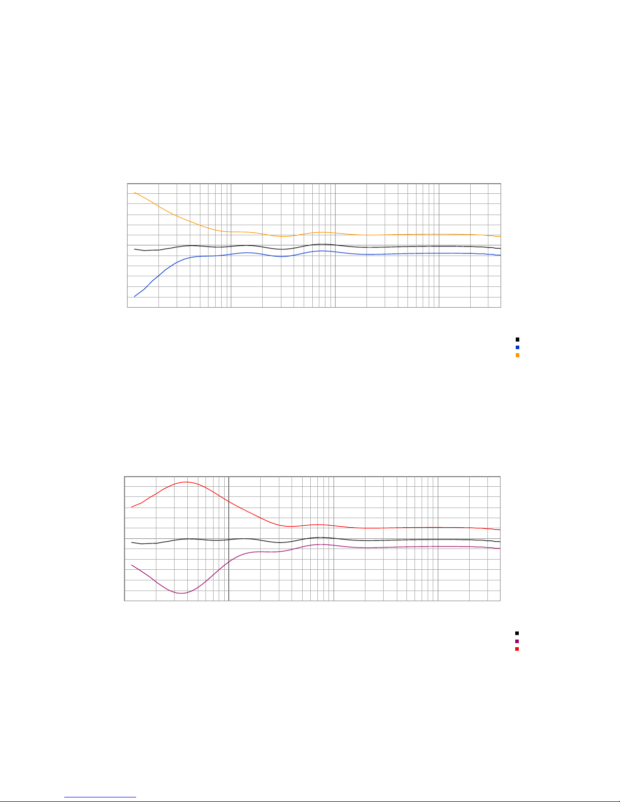
SUB (10 Hz)
Fixed frequency, bell shaped boost and cut (+/- 5.5 dB @ 0.5 dB steps)
TIP
: The 10 Hz frequency can be utilized as a 40 Hz HIGH PASS filter at full -5.5 dB cut!
40 Hz
Fixed frequency, bell shaped boost and cut (+/- 5.5 dB @ 0.5 dB steps)
Bypass
Sub Max Cut
Sub Max Boost
Bypass
Sub Max Cut
Sub Max Boost
0
-6
-5
-4
-3
-2
-1
1
2
3
4
5
6
Magnitude (dB)
10 100 1k 10k
Frequency (Hz)
Frequency Response
Bypass
Sub Max Cut
Sub Max Boost
Bypass
40Hz Max Cut
40Hz Max Boost
Bypass
40Hz Max Cut
40Hz Max Boost
0
-6
-5
-4
-3
-2
-1
1
2
3
4
5
6
Magnitude (dB)
10 100 1k 10k
Frequency (Hz)
Frequency Response
Bypass
40Hz Max Cut
40Hz Max Boost
Page 7
| 7
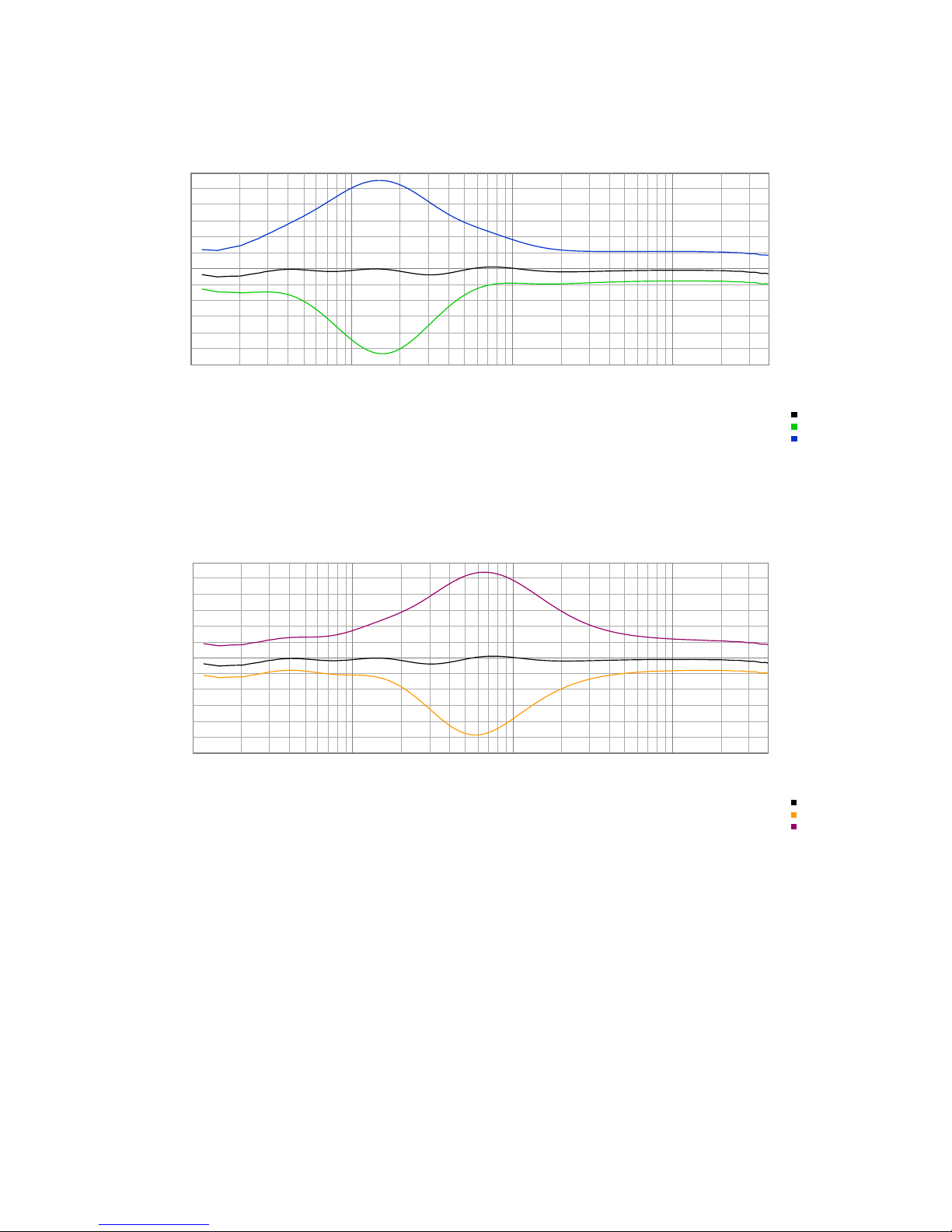
160 Hz: Fixed frequency, bell shaped boost and cut (+/- 5.5 dB @ 0.5 dB steps)
650 Hz: Fixed frequency, bell shaped boost and cut (+/- 5.5 dB @ 0.5 dB steps)
Bypass
160Hz Max Cut
160Hz Max Boost
Bypass
160Hz Max Cut
160Hz Max Boost
0
-6
-5
-4
-3
-2
-1
1
2
3
4
5
6
Magnitude (dB)
10 100 1k 10k
Frequency (Hz)
Frequency Response
Bypass
160Hz Max Cut
160Hz Max Boost
Bypass
650Hz Max Cut
650Hz Max Boost
Bypass
650Hz Max Cut
650Hz Max Boost
0
-6
-5
-4
-3
-2
-1
1
2
3
4
5
6
Magnitude (dB)
10 100 1k 10k
Frequency (Hz)
Frequency Response
Bypass
650Hz Max Cut
650Hz Max Boost
Page 8
!
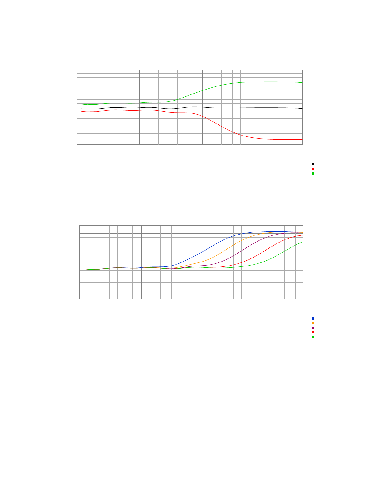
2.5 kHz: Fixed frequency, high shelf boost and cut (+/- 5.5 dB @ 0.5 dB steps)
PRESENCE: Selectable frequency as indicated, high shelving boost (+ 11 dB @ 0.5 dB steps)
Bypass
2k5Hz Max Cut
2k5Hz Max Boost
Bypass
2k5Hz Max Cut
2k5Hz Max Boost
-10
0
10
Magnitude (dB)
10 100 1k 10k
Frequency (Hz)
Frequency Response
Bypass
2k5Hz Max Cut
2k5Hz Max Boost
Presence Max 2k5Hz
Presence Max 5kHz
Presence Max 10kHz
Presence Max 20kHz
Presence Max 40kHz
Presence Max 2k5Hz
Presence Max 5kHz
Presence Max 10kHz
Presence Max 20kHz
Presence Max 40kHz
0
10
Magnitude (dB)
10 100 1k 10k
Frequency (Hz)
Frequency Response
Presence Max 2k5Hz
Presence Max 5kHz
Presence Max 10kHz
Presence Max 20kHz
Presence Max 40kHz
Page 9
| 9
INTERNAL ADJUSTMENTS
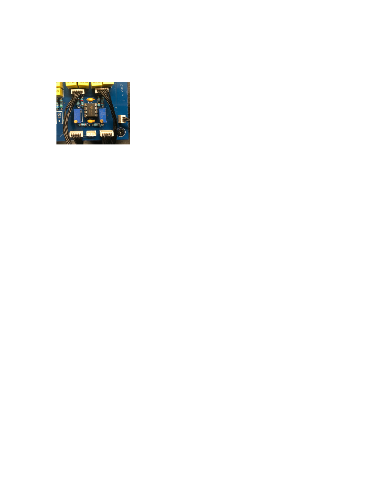
INPUT GAIN ADJUSTMENT
The EQ-6S has internal INPUT GAIN adjustment trimmers for both left and right channels and is
calibrated before shipment. If further adjustment is required, unity gain calibration can be
performed as follows:
1. Ensure the equipment is powered OFF and the IEC power cable is unplugged, but the XLR
input and output cables are connected.
2. Viewing from the top of the enclosure, unscrew the two (2) Philips head screws that are
located toward the rear of the case and carefully pry the lid upward; a suction cup is
handy for this task.
3. Carefully plug the IEC power cable and push both
POWER
button to be illuminated.
4. Feed a -12 dB, 1kHz sine wave tone using a signal generator from your DAW into each
channel and take a note of the signal on each channel of your DAW software where the
generator is feeding the EQ-6S channels (e.g. -10.5 dBFS).
5. Now push the IN button to be illuminated and take a note of the DAW master output
signal, reset this signal by clicking the indicated dB signal of the channel (e.g. -11.2
dBFS).
6. Adjust the trimmer for each channel separately and ensure that the master output
measures the same as the the measurement taken in step 4 (e.g. -10.5 dBFS).
7. Once both channels have the same signal measure when both IN and bypassed,
calibration is complete.
8. Carefully POWER OFF the unit and re-assemble the lid by sliding the lid firstly toward the
front of the unit at an angle, then dropping the rear of the lid into the enclosure. Screw
the two (2) Philips head screws back into the enclosure.
Page 10
!
SPECIFICATIONS
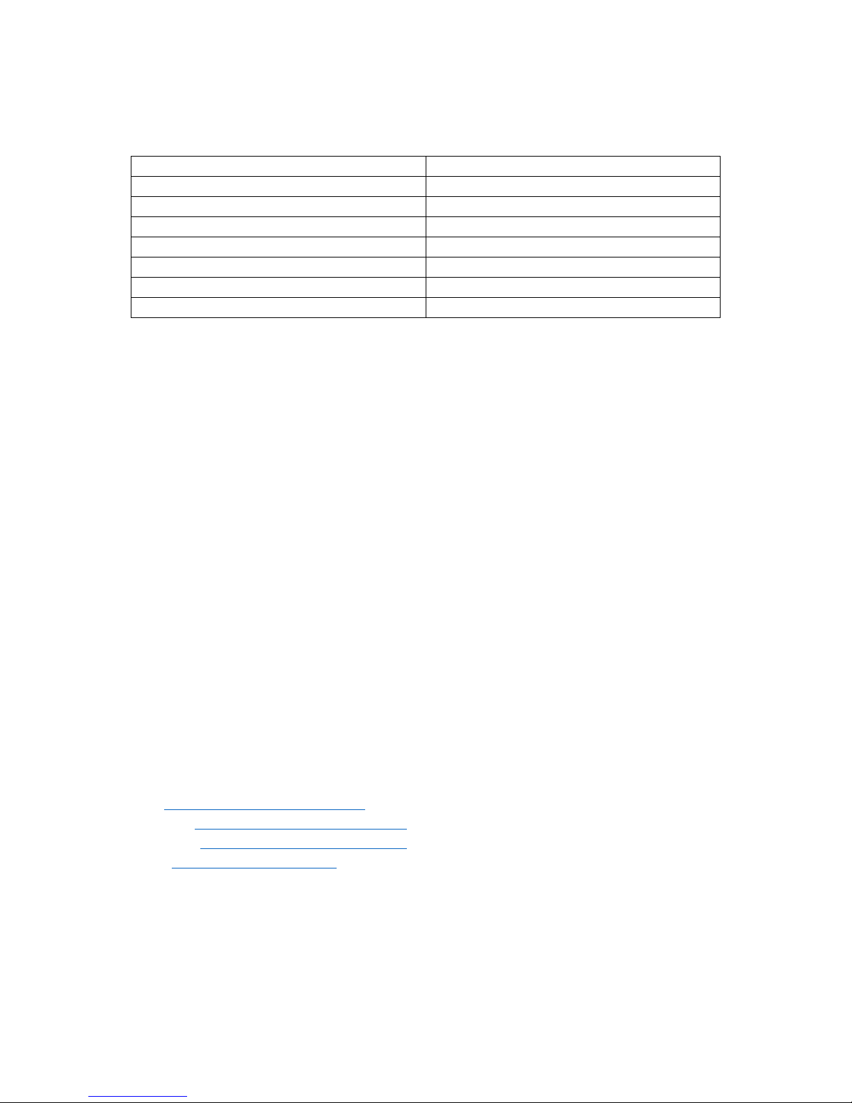
Frequency Response
+/- 0.3 dB, 10 Hz to 70 kHz
Maximum headroom
Approximately +28 dBu @ 10K Ohms
Noise floor
< -105 dB SNR
Total harmonic distortion
< 0.003%
Input Impedance (balanced)
48 K Ohms
Output Impedance (balanced)
50 Ohms
Replacement fuses (M205)
USA (100-120VAC) 200mA Slo-Blo
EU, AU (200-240VAC) 100mA Slo-Blo
*Specifications subject to change without notice.
WARRANTY
HIGH VOLTAGE AUDIO warrant our products with a standard warranty period of one (1) year
from the date of purchase for parts and labour, subject to inspection. Products will be free of
manufacturing defects. This warranty does not include damage incurred through shipment,
rough user operation of the product or modifications or attempted repair by unauthorized
personnel. This warranty is offered solely to the original purchaser of the product, directly from
HIGH VOLTAGE AUDIO and is not transferrable. This warranty does not include shipping charges
to and from HIGH VOLTAGE AUDIO.
Warranty service communication must be conducted directly through HIGH VOLTAGE AUDIO.
HIGH VOLTAGE AUDIO reserves the right to alter the design of their products and specifications
without notice.
CONTACT
web: http://www.highvoltageaudio.net
facebook: http://www.facebook.com/hvaudio
instagram: http://www.instagram.com/hvaau
email: [email protected]
Page 11

| 11
HIGHgVOLTAGE
A U D I O
Page 12
!
!
COPYRIGHT © 2018 HIGH VOLTAGE AUDIO
 Loading...