

Page 1
PFT
SERIES
Safety , Operation, and Procedure In structions for the PFT Series of
AC Hipots
Please Refer to
Documentation
Before Operation
Danger- Lethal Voltages:
Equipment to be used by trained personnel only
This Operator Manual contains instructions for the operation of a High Voltage power source. The operator of this equipment
must use good judgement and follow all safety precautions noted in this guide to ensure the protection of himself and others in
close proximity to the test area. Failure to follow the instructions could result in injury or
death. Proper grounding of the test set must be done prior to connecting this unit
to a power source.
Page 2

Operator Manual
Page 3

Table of Contents
About the Operator Manual 1
SECTION 1
General Information 2
Features and Specifications 2-3
Controls and Indicators 4-5
SECTION 2
Setting up the Equipment 6
Operating the Equipment 7-10
Blank Page for Notes 11
SECTION 3
Performing Special Operations 12
Meter Re-calibration 12,13
Miscellaneous 14
Packing the Cables 14
Return Material 15
Warranty 16,17
T:\PRODUCT\DOCUMENTS\Manuals\PFT\MANpft_2k9Re.doc
Last saved 1/29/2009
Page 4

OPERATOR MANUAL
About the Operator Manual
Important
This Operator Manual describes the features and safe operation of a High
V oltage Test Set. The instructions are intended to be clear and simple, but
the operator must be trained and qualified according to established
procedures for the use of this type of equipment.
This Operator Manual is organized to provide information on the PFT Series of Hipots in steps that familiarize
the new operator with the operation of this test set.
Section 1: Specifications and Controls.
Section 2: Setup and Operation.
Section 3: Performing Special Operations.
The Functions, Features, and Spec ifications of the PFT Series of AC Hipots are also discussed in the PFT Brochure
available from High Voltage, In c.
- 1 -
Page 5

SECTION
1
General Information
This section familiarizes the operator with the features and specifications of the
PFT Series of Power Frequency AC Test Sets manufactured by HIGH VOLTAGE, INC.
Fea tures and Specifications
The PFT Series of AC hipot test sets provide continuously adjustable output voltages for the GO/NO-GO
testing of high voltage insulation. Earlier versions of the PFT Series were equipped with operator controlled
capacitive compensation switches to minimize input primary currents. The new simplified controls incorporate
this feature transparently.
Standard features of the PFT Series of include:
• Continuously adjustable output voltage
• Fixed overload, factory set to 120% of variable transformer rated output current
• “Zero Start” and External Interlock provision
• Secondary connected dual-range voltmeter
• Shielded output cable (50 kV and below) precludes unnecessary insulated support of the cable
• One piece portable design (50 kV and below)
• Transit protected meters prevent meter damage between test sites
• Capacitive load compensation incorporated to allow up to 3 KVA output power with less than 15
Amperes input line current.
• Fault Burn Reactor (Optional)
2
Page 6

PFT MODEL SPECIFICAT IONS
PFT-103
Table 1 PFT Series Specifications.
PFT-303
PFT-503
PFT-1003
SEE SPECIFICATIONS
ON LAST SHEET OF PARTS LIST
3
Page 7

VOLTMETER
LOW HIGH
PLEASE REFER TO
DOCUMENTATION
BEFORE OPERATION
OUTPUT
GROUND
CURRENT RANGE
X10
LOAD
RETURN
X100
X1
RETURN
MODE
GUARDGROUND
MAIN
POWER
EXT
INPUT
FUSE
AC TEST SET PFT SERIES
INTLK
HIGH
VOLTAGEOFF ON
Figure 1 PFT Series front panel controls.
MAIN POWER
The MAIN POWER pushbutton switch provides the power to the control and power circuits. The neon lamp in
the switch will light when the power is on and voltage is available through the input line cord. The INPUT
FUSE located electrically before the MAIN POWER switch provides line fault protection for the unit.
EXT INTLK (EXTERNAL INTERLOCK)
The Ext Intlk connector is provided to allow for a normally open safety interlock switch to control the
energizing of the high voltage output.
HIGH VOLTAGE ON/OFF
The HIGH VOLTAGE ON and OFF pushbuttons control the high voltage power circuits. The red and green
LEDs provide life long positive indication of the circuit status. The red LED lights when high voltage is
energized and the green LED lights when the high voltage is de-energized.
OUTPUT CONTROL
The OUTPUT control variable transformer adjusts the output voltage. The 0-10 markings on the knob indicate
the low to high setting. The control must be at ZERO (0) to energize the high voltage circuits. The output
control must always be returned to zero at the completion of testing, prior to de-energizing the output
4
Page 8

VOLTMETER AND RANGE SWITCH
The KILOVOLT METER and associated range switch allows for more accurate output voltage readings. 1-%
precision resistors minimize the need for re-calibration due to aging shift. See Voltmeter Re-calibration in
Section 3 for details on calibration.
CURRENT METER
The CURRENT METER is for accurate secondary load current readings. The range multiplier switch (X1,
X10, X100) allows readings to be taken as low as .1mA (5 divisions) and up to 100mA.
LOAD RETURN CONNECTOR
The LOAD RETURN connector is for the low side of the test load. It connects to the shielded return lead for
more accurate load current readings.
RETURN MODE
The RETURN MODE switch allows for accurate secondary load current readings. In the GUARD position, all
ground currents are shunted around the meter. The load must be isolated from ground to use in the GUARD
position. In the GROUND position, the return point is grounded and all currents (load and ground losses) are
metered.
BURN(OPTIONAL)
The BURN toggle is provided for tests when the load has faulted and the insulation must be further scored to
find the problem. The BURN feature will limit current on the output below the overload value and allow for
thorough marking of the fault area.
List of included components
Black test lead with black boot for ground connections. (2 leads for PFT-1003)
Ext. Intlk. Jumper plug
Attached 20 ft. X-Ray shielded output cable (50kV and below)
Alligator and hook connections for working end of output cable (50kV and below)
20 ft. RG58/U coax return lead
5
Page 9

SECTION
2
SETTING UP THE EQUIPMENT
The setup of this equipment has been minimized by careful consideration of the operator during design. The
PFT Series’ one-piece construction (50kV and below) minimizes misplaced components while allowing for
convenient portability.
1. Select a location for the unit that will allow easy viewing of the meters at a safe distance
from the test object.
2. Be sure that all the controls are off, in their de-energized or fully counterclockwise
position.
3. Secure a ground test lead to the panel. The Ground post on the front panel should be
used for that purpose. A black test lead with black boot has been provided for the ground
connection. A second ground lead is provided for two-piece units for the grounding of the high
voltage section.
4. Insert the EXT INTLK plug into the socket on the panel. The plug may also be
wired to a normally open contact of a safety switch for added protection. Hand-held safety
switches are available from High Voltage to plug directly into the EXT INTLK socket.
5. If applicable, connect the interconnect cable between the control and high
voltage section.
6. The red booted alligator clamp on the output cable is used to connect the output cable to the test
object. (50kV and below). Connection of the output toroid on the PFT-1003 high voltage section
to the load is accomplished by using a customer provided test lead or tubing (metallic) between
the toroid (HV output) and test object.
6
Page 10

Operating the Equipment
This section provides step-by-step instruction on various test methods. Many facilities have their own
in-house test procedures that should not be superceded by this manual. The purpose of this section
is to explain the capabilities of this test set in real-world applications.
AC Insulation Testing
1. Ensure that all the steps listed in Setting up the Equipment have been accomplished. Take
special note to ground the control panel to a solid earth ground using the supplied black test
lead.
2. Select the desired VOLTMETER RANGE for the test voltage level expected.
3. Prior to connecting the output cable (toroid) to the test sample, be sure that the test sample is
de-energized.
4. Connect the output lead to the test sample. Be sure that there is enough clearance to
grounded objects for the expected test voltage. The minimum clearance in air is 10 kV
ac/inch.
5. Return the low side of the test sample to the LOAD RETURN connector using the supplied
shielded return lead. See the GUARD/GROUND explanation (pp. 9,10) for direction on which
mode may be appropriate for your testing requirements.
6. Connect the input power cord to a grounded source (See the specification table for unit input
requirements).
7. Depress the MAIN POWER switch to energize the control circuits.
7
Page 11

***CAUTION***
POTENTIALLY LETHAL VOLTAGES
MAY BE PRESENT
8. With the OUTPUT control at zero (zero start interlock engaged), depress the HV ON
pushbutton. The HV ON light will glow.
9. Increase the output by rotating the OUTPUT control slowly clockwise until the desired output
voltage is reached.
Note: The high voltage output cable shield is grounded. This grounded shield appears as a
load even under ‘no load’ conditions. The current on a PFT-503CM is about 18mA at full
output with the RETURN MODE in the GROUND position.
10. Maintain the output voltage for the test time specified in your standard procedures.
11. After the test is complete, rotate the OUTPUT control to zero, prior to depressing the HV OFF
pushbutton.
12. If the test sample fails during the test, the internal overload relay will de-energize the high
voltage. This relay is in the primary circuit and is sensitive to primary current overloads.
The overload is set to 120% of the rated current of the variable transformer. The use of a
gapped transformer in the high voltage tank will null the primary currents (up to 1.5 KVA) and the
overload will allow operation to the full output rating of 3 KVA. When testing purely resistive
loads, the unit will overload above 1500 VA of input power to the tank.
13. Prior to removing the output cable from the load, observe that the output voltmeter is at zero.
14. Always ground the output cable (or toroid) and test sample prior to disconnecting the
test object.
8
Page 12
Using the Guarded Return
The use of the GUARD/GROUND return feature of this test set provides for very accurate leakage current
measurements if certain conditions exist allowing for the GUARD circuit to be employed. The following
explanation will detail different test samples and methods that lend themselves to the use of this circuit. The
same setup precautions such as proper grounding still apply to the test but the grounds will be manipulated to
accomplish the test requirements.
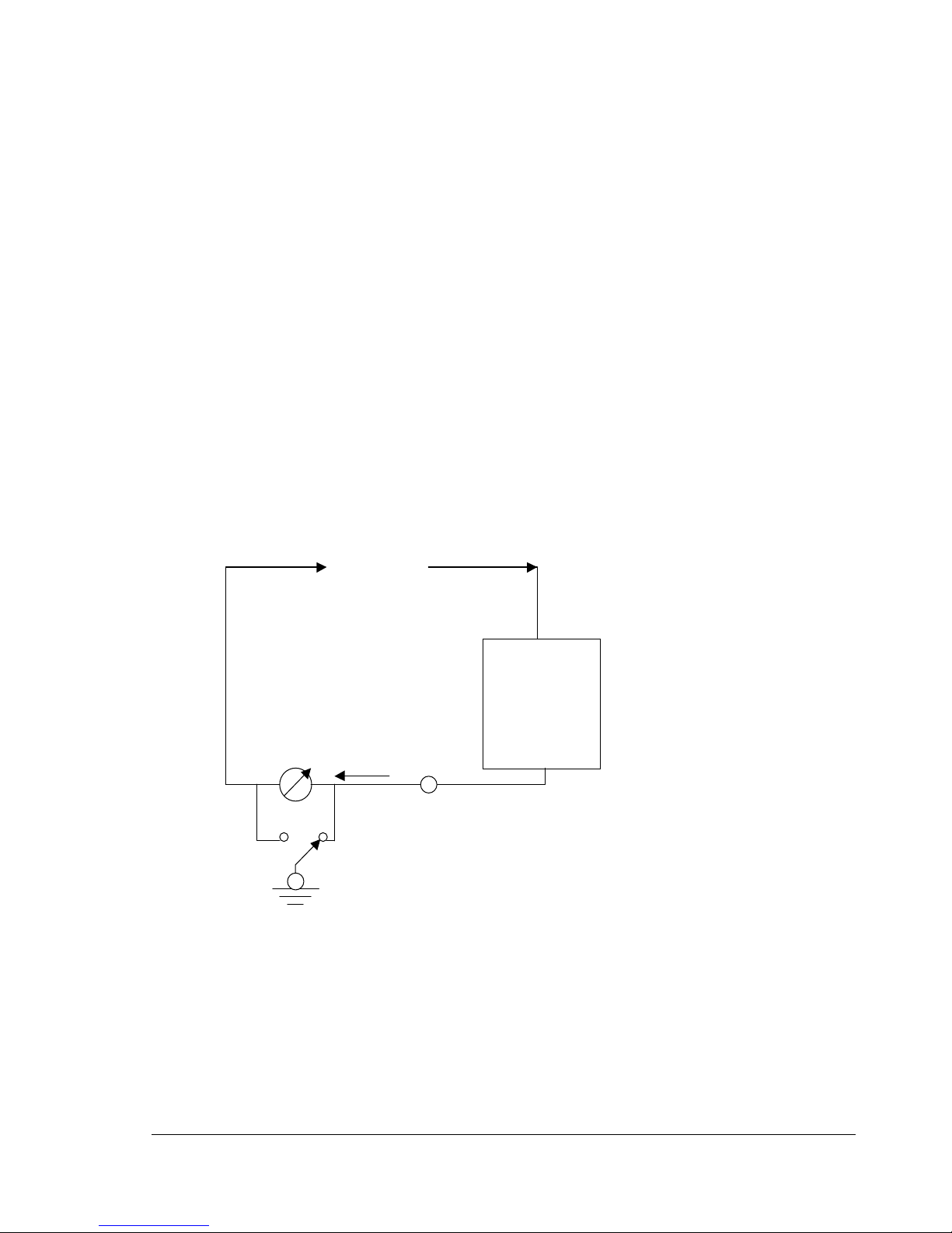
1. Grounded Return- With the output return in the grounded mode, the current meter reads all
current to ground, internal and external to the test set. This current might include corona, surface
tracking, and any shunt resistance. The typical diagram for grounded return operation is shown
in Figure 2 below.
2. Guarded Return- With the output return in the guarded mode, the current meter will only read
currents through the test sample. The test sample must be isolated from ground on the low side
as shown in Figure 3 below.
High
Voltage
From Test
Set
Meter
GUARD GROUND
GROUND
POST
RETURN
POST
Current flow through
ret urn includes all
curr ent to gro und
Figure 2, Grounded Return Diagram
Test
Sample
9
Page 13
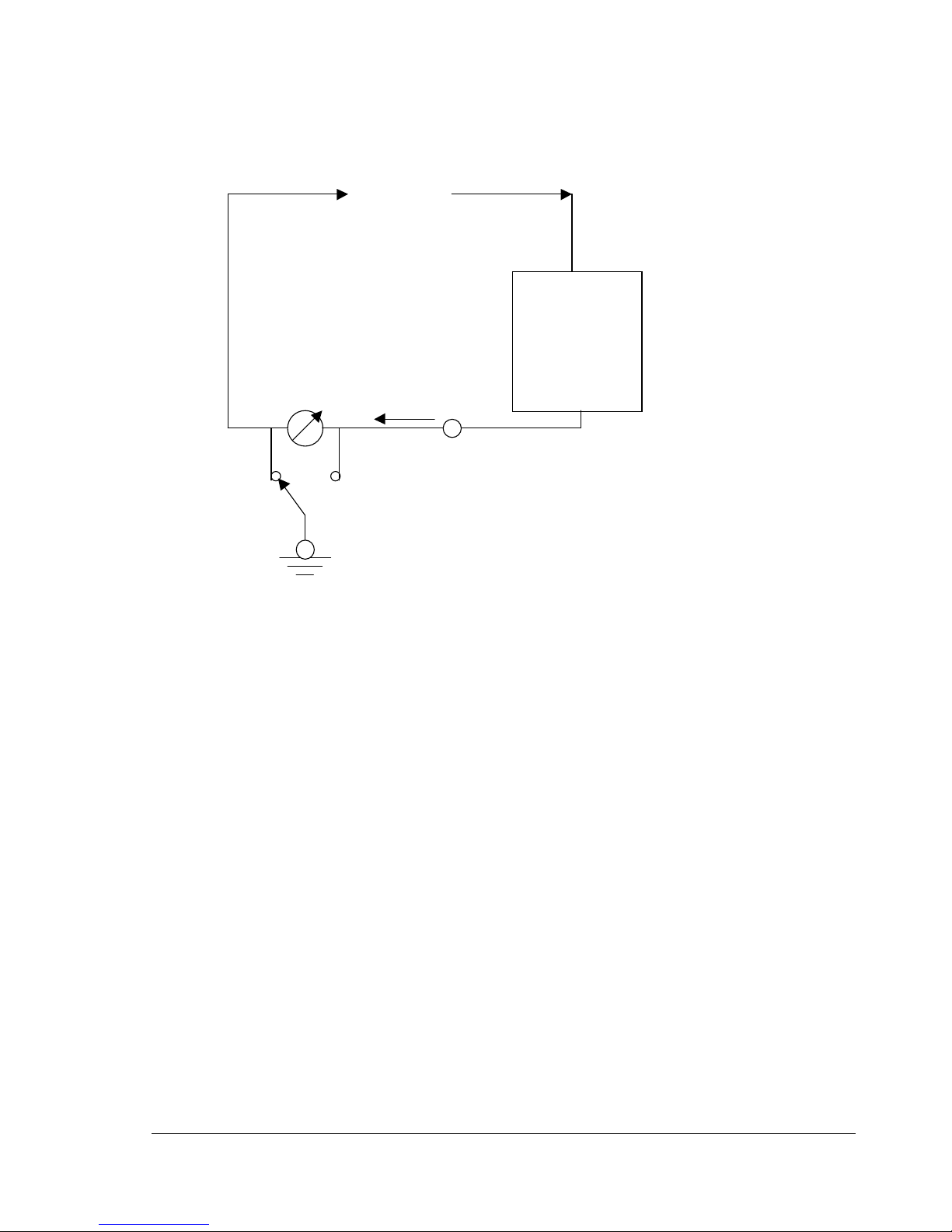
High
Voltage
From Test
Set
Test
Sample
Meter
RETURN
POST
Current flow through
return includes only current
GROUNDGUARD
through the test sample.
Note that the current to
ground is r et urned after t he
GROUND
meter.
POST
Figure 3, Guarded Return Diagram
10
Page 14

THIS PAGE LEFT BLANK FOR APPLICATION NOTES
11
Page 15

SECTION
PERFORMING SPECIAL OPERA TIONS
The following section contains information on the care and upkeep of your new PFT SERIES Power
Frequency AC Test Set. There are some notes on troubleshooting and service, which will save much time
and money over the life of the unit.
Meter Re-calibration
The PFT SERIES of hipots use precision metal film resistors for measurement and calibration of the
voltmeter. The use of these resistors in both the high voltage tank and the metering circuits has minimized
circuit drift due to aging and temperature. Adjustment of potentiometer (R4) on the voltmeter and current
meter PCB can be used to correct for movement changes from the aging of the meter.
The certification of meters on a yearly basis is recommended to ensure accurate test
results.
Voltmeter Re-calibration
1. Locate the unit in a position that will allow easy reading of the meters.
2. Remove the panel screws and support the panel vertically to gain access to the calibration pot
on the back of the voltmeter.
3. Zero the meter movement using the zero adjustment below the scale window.
4. Perform the steps in Setting up the Equipment at the start of SECTION 2. Be sure to ground
the front panel to a solid earth ground using the supplied black ground test lead prior to
connecting the unit to input power.
5. Set the VOLTMETER RANGE to LOW position.
6. Connect the output cable to a calibrated reference meter with ability to read to the full output
voltage of the unit. Be sure to ground the low side of the meter.
12
Page 16

7. Raise the output to one half scale on the unit meter. Adjust R4 as required.
8. Check calibration at full scale and on the high range at both half and full scale. If the customer
facility calibration certification requires more points of reference, follow those procedures instead
of these.
9. Calibration must then be verified with the panel in the horizontal operating position to check for
any meter balance affect on the calibration.
Current Meter Re-calibration
10. Locate the unit in a position that will allow easy reading of the meters.
11. Remove the current meter panel screws and support the panel vertically to gain access to the
calibration pot on the back of the current meter.
12. Zero the meter movement using the zero adjustment below the scale window.
13. Perform the steps in Setting up the Equipment at the start of SECTION 2. Be sure to ground
the front panel to a solid earth ground using the supplied black ground test lead prior to
connecting the unit to input power.
14. Set the CURRENT RANGE to X1 position.
15. Connect the output cable to a calibrated reference meter with ability to read 1mA ac. Use a
series resistance or capacitance to allow for precise resolution when calibrating. Be sure to
connect the low side of the reference current meter to LOAD RETURN and place the RETURN
MODE switch in GUARD position.
16. Raise the output to one half scale on the unit meter. Adjust R4 as required.
17. Check calibration at full scale. If the customer facility calibration certification requires more points
of reference, follow those procedures instead of these.
18. Calibration must then be verified with the panel in the horizontal operating position to check for
any meter balance affect on the calibration.
19. Check other ranges to verify accuracy. 1% range resistors should not require any adjustment on
higher ranges. The output current can only be run to full output current with a capacitive load.
Resistive loads are limited to about 1/2 rated current.
13
Page 17

Miscellaneous
Oil Insulated High Voltage Tanks
The oil-filled tanks in all the PFT SERIES of hipots are field serviceable. The only requirement is that the tank
must be oil filled under vacuum at re-assembly if left out of the oil for longer than 3 hours. The parts to service
the tank are available from HIGH VOLTAGE, INC. at the address noted on the inside front cover of this
manual.
The oil level in the tank should be .5 inches from the lid when the oil temperature is 20°C.
Packing the Cables
The output cable will easily fit into the cable storage area next to the control panel. Care should be used to
avoid damaging the output cable jacket when coiling into the compartment. As the final step, the ground and
return leads will coil neatly inside the output cable coil.
14
Page 18

RETURNED MATERIAL
If for any reason it becomes necessary to return any equipment or materials to High Voltage,
Inc., the Service Department of High Voltage, Inc. must be notified, and authorization received,
prior to the shipment of the equipment. When notified, the following information must be
provided:
MODEL:
SERIAL NO:
PART NO:
REASON FOR RETURN:
SUSPECTED DEFECT:
CAUSE OF DEFECT:
With the above information provided, High Voltage, Inc. will determine if the return of the
equipment is appropriate. If deemed appropriate, a Return Authorization Number will be
issued. At that time, the Purchaser will be instructed how to mark and return the equipment.
The above procedure must be adhered to in order to ensure prompt service. No equipment
should be returned without the prior knowledge and authorization of High Voltage, Inc.
REPLACEMENT PARTS ORDERING
To order replacement parts, first refer to the Parts List for the product in question. Every part is
issued a part number. It is necessary for this part number and the product model and serial
number to be provided. When calling High Voltage, Inc. request the Service Department.
15
Page 19

* * * * * * * * * * * * * * * * * * * * *
LIMITED WARRANTY; LIMITED RESPONSIBILITY FOR DAMAGES
High Voltage, Inc. (“High Voltage”) warrants to the original purchaser of any new product, purchased
from High Voltage, that the product is free from defects in material and workmanship under normal use
and service for a period of one year from the date of shipment to the original purchaser by High
Voltage.
This warranty is valid only for normal use of the product. Any use outside High Voltage’s written
operation instructions will void this warranty. In addition, any one of the following events will void this
warranty: (a) any defects due to negligence, alteration, modification, accidental or intended physical
abuse, faulty installation, and/or misuse: (b) attempted or actual dismantling, service or repair by any
person or firm not authorized in writing by High Voltage: (c) defects caused due to handling or transit,
either by carrier or purchaser.
This warranty only covers those parts deemed defective by High Voltage The liability of High Voltage
is limited to only the repair, replacement with new or reconditioned parts, or issuance of credit for those
parts deemed defective within the scope of this warranty. Any additional costs incurred by the
purchaser for labor and/or materials incidental to the inspection, repair, replacement or issuance of
credit for product or materials under warranty is the sole responsibility of the purchaser. This warranty
applies solely to products manufactured by High Voltage. It does not apply to parts, accessories, or
materials not manufactured by High Voltage, or to consumables. If purchaser’s claim relates to
materials manufactured by a supplier to High Voltage, High Voltage reserves the right to disclaim
responsibility and liability and may require the purchaser to deal directly with the other manufacturer of
the defective part. High Voltage may elect to assist the purchaser in settling such claim against such
other manufacturer without prejudicing High Voltage’s position as to its own liability.
WARRANTY CLAIM PROCEDURE
Compliance with the following Warranty Claim Procedure is a condition precedent to the obligation of
High Voltage under this warranty:
a) Purchaser must notify High Voltage as soon as is reasonably possible of any alleged defect in
material, workmanship, or operation of any product covered under this warranty, provided that
any notification must be received by High Voltage within twelve months after the shipment date
of the product in question. Such notice must describe in detail the defect, any and all defective
parts, and the alleged cause of the defect.
16
Page 20

b) At the exclusive option of High Voltage, purchaser may be directed to dismantle the product at
the purchaser’s cost and expense and ship the product prepaid to High Voltage Refer to the
Returned Material section for instructions regarding the return of any material to High Voltage
If High Voltage elects to inspect the product at the purchaser’s site, and possibly repair,
replace, or ship the defective product to High Voltage’s factory, purchaser, at its own cost and
expense, shall provide suitable facilities for such work as needed to inspect and evaluate and
possibly repair/replace subject product. If inspection discloses that the defect is not one for
which High Voltage is liable, that is, is outside the stated terms of this warranty provided by
High Voltage, then the purchaser agrees to reimburse High Voltage for all expenses incurred.
c) Upon receipt of the defective material or product, or following access to the same, High
Voltage shall inspect and evaluate the material or product and determine the validity of the
purchaser’s claim.
The validity of any warranty claim, the purchaser’s compliance with this warranty and Warranty Claim
Procedure, and the obligation to replace, repair, or issue credit for any product, shall be solely and
exclusively determined by High Voltage and any determination shall be final and binding.
THIS WARRANTY IS EXPRESSLY IN LIEU OF ALL OTHER WARRANTIES EXPRESSED OR
IMPLIED ON THE PART OF HIGH VOLTAGE, INCLUDING THE WARRANTIES OF
MERCHANTABILITY, FITNESS FOR A PARTICULAR USE, AND NON-INFRINGEMENT ARISING
FROM ANY BREACH THEREOF AND HIGH VOLTAGE NEITHER ASSUMES NOR AUTHORIZES
ANY OTHER PERSON, FIRM , OR CORPORATION TO ASSUME ANY LIABILITY OR OBLIGATION
IN CONNECTION WITH THIS WARRANTYON ITS BEHALF AND PURCHASER ACKNOWLEDGES
THAT NO REPRESENTATIONS EXCEPT THOSE MADE HEREIN HAVE BEEN MADE TO
PURCHASER. THIS WARRANTY SHALL BE GOVERNED AND CONSTRUED ACCORDING TO
THE INTERNAL LAWS OF THE STATE OF NEW YORK.
LIMITATION OF LIABILITY. TO THE MAXIMUM EXTENT PERMITTED UNDER APPLICABLE LAW,
AND NOTWITHSTANDING ANYTHING ELSE IN THIS DOCUMENT OR OTHERWISE, INCLUDING
THAT HIGH VOLTAGE WAS WARNED THAT DAMAGES WOULD OCCUR OR WERE LIKELY TO
OCCUR, HIGH VOLTAGE SHALL NOT BE LIABLE UNDER ANY CONTRACT, NEGLIGENCE,
STRICT LIABILITY OR OTHER LEGAL OR EQUITABLE THEORY FOR (A) ANY AMOUNTS IN
EXCESS IN THE AMOUNT PAID TO HIGH VOLTAGE FOR THE PARTICULAR PRODUCT OR
PART THEREOF WHICH GAVE RISE TO THE APPLICABLE CAUSE OF ACTION, OR CLAIM, OR
(B) ANY INCIDENTAL OR CONSEQUENTIAL DAMAGES, LOST PROFITS OR LOST DATA, OR (C)
COST OF PROCUREMENT OF SUBSTITUTE GOODS, TECHNOLOGY OR SERVICES. HIGH
VOLTAGE SHALL HAVE NO LIABILITY FOR ANY FAILURE OR DELAY DUE TO MATTERS
BEYOND ITS REASONABLE CONTROL.
17
Page 21

Parts List PFT-1003CM (120V)
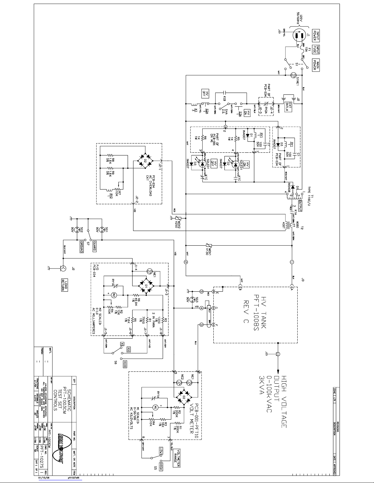
Schematic # PFT-1027S
REF. QUAN HVI# DESCRIPTION
CAB 1 32-033 CABINET, PORTABLE TRANSIT ENCLOSURE. CHARCOAL GRAY.18W x 10D x 14 H ID
D1 1 04-030 DIODE, 1N5408A
D2,3 2 04-025 DIODE, 1N4007A
F1 1 06-043 FUSE, 15A, 250V, ABC-15
1 06-015 FUSE HOLDER, LITTELFUSE # 342004A
J2 1 07-440 CONNECTOR, BULKHEAD, 2 SOCKET, CINCH #S302AB
J3 1 CONNECTOR, BULKHEAD, CIRCULAR, PART OF HIGH VOLTAGE TANK
J4 1 07-206 CONNECTOR, BULKHEAD, BNC, AMPHENOL # UG1094A/U
K1 1 11-150 CONTACTOR, 3PDT , 15A, 120 Vac COIL, MAGNECRAFT # W389ACX-14
M1 1 13-141
M2 1 13-151
MOV1 1 06-207 METAL OXIDE VARISTOR, # V130LA10A
MOV2 1 06-210 METAL OXIDE VARISTOR, # V250LA20A
P1 1 22-205 INPUT POWER CABLE, 16/3, 12 ft.
P2 1 07-442 CONNECTOR, CABLE, 2 CIRCUIT, CINCH# P302CCT
P3 1 07-014 CONNECTOR, CABLE, 7 PIN CIRCULAR, AMPHENOL # 97-3106B-20-15S
PCB-001-PFT10 1 82-275 PRINTED CIRCUIT BOARD, VOLT METER
PCB-034 1 82-274 PRINTED CIRCUIT BOARD, AC OVERLOAD/CURRENT METER
S1 1 10-214 SWITCH, PB, MAINT’D, 250 Vac, 15A, DPST, NO , NEON LAMP, MICROSWITCH
1 10-250 SWITCH, PB COVER, BLACK, MICROSWITCH # AML52-N10K
S2 1 10-222 SWITCH, PB, MOM., 125 Vac, 15A, SPDT, GRN LED, MICROSWITCH # AML22CBS2AA
S3 1 10-218 SWITCH, PB, MOM., 125 Vac, 15A, SPDT, RED LED, MICROSWITCH # AML22CBC2AA
2 10-252 SWITCH, PB COVER, BLACK, MICROSWITCH # AML52-C10K
S4 1 10-106 SWITCH, SNAP ACTION, SHORT ARM, OMRON #A-20GV22-B7-K
S5 1 10-514 SWITCH, ROTARY, 6 POL, 2 POS, MOUSER # 10YX062
S6 1 10-510 SWITCH, ROTARY, 4 POL, 3 POS, MOUSER # 10WW043
S7 1 10-402 SWITCH, ROCKER, DPDT, CARLINGSWITCH # 62115929-0-0-V
SG1-3 3 06-205 SPARK GAP, 90V, CP CLARE, CG90L
T1 1 25-108 TRANSFORMER, VARIABLE, SUPERIOR TYPE 116
T2 1 T080 TRANSFORMER, CURRENT, HVI #080
HV TNK 1 84-240 TANK, HIGH VOLTAGE 100 kVac , HV # PFT-1008S REV C
PCB-001-
PFT10
C1 1 03-060
D1 1 04-025 DIODE, 1N4007A
D2 1 04-415 DIODE, FULL WAVE BRIDGE, 1.5A, 1kVdc, MOUSER # 583-RB157
J1 1 07-136 CONNECTOR, HEADER, 8 PIN, .1” SPACING, MOLEX # 22-23-2081
NE1,2 2 15-114 NEON LAMP, #NE2
P1 1 07-120 CONNECTOR, CABLE, 8 PIN, .1” SPACING, MOLEX # 22-01-2087
PCB 1 14-001 PRINTED CIRCUIT BOARD, HVI # PCB- 001
R1,2 2 01-154 RESISTOR, METAL FILM, 0.25W, 200K, 1%
82-275 VOLT METER PCB
8 07-104 CONNECTOR PINS, .1” SPACING, MOLEX # 08-50-0114
METER, ANALOG, 100 µA MOVEMENT, SCALED 0-50/100 AC KILOVOLTS
METER, ANALOG, 100 µA MOVEMENT, SCALED 0-1.0 AC MILLIAMPERES
#AML32FBB4AD
CAPACITOR, ELECTROLYTIC, RADIAL LEADS, 100µF, 50 Vdc, MOUSER # 140-XRL50V100
Saved 10/7/2008 9:08:00 AM, T:\PRODUCT\DOCUMENTS\Manuals\PFT\pl_pft1003CM_2k8Ri.doc
Page 1 of 3
Page 22

R3 1 01-114 RESISTOR, METAL FILM, 0.25W, 18K, 1%
R4 1 02-108 RESISTOR, POTENTIOMETER, 0.25W, 10K, MOUSER # 569-25PR-10K
R5,6 2 01-310 RESISTOR, CARBON FILM, 1W, 1K, 5%
RY1 1 11-110 RELAY, PCB MOUNT, SPDT, 24 Vdc COIL, P&B # T70L5D131-24
PCB-034
C1 1 03-060
D1,2 2 04-415 DIODE, FULL WAVE BRIDGE, 1.5A, 1kVdc, MOUSER # 583-RB157
D3 1 04-025 DIODE, 1N4007A
J1 1 07-136 CONNECTOR, HEADER, 8 PIN, .1” SPACING, MOLEX # 22-23-2081
J2 1 07-130 CONNECTOR, HEADER, 5 PIN, .1”SPACING, MOLEX # 22-23-2051
NE1 1 15-114 NEON LAMP, #NE2
P1 1 07-120 CONNECTOR, CABLE, 8 PIN, .1”SPACING, MOLEX # 22-01-2087
P2 1 07-114 CONNECTOR, CABLE, 5 PIN, .1”SPACING, MOLEX # 22-01-2057
PCB 1 14-034 PRINTED CIRCUIT BOARD, HVI # PCB-034
R1 1 01-054
R2 1 01-092 RESISTOR, METAL FILM, 0.25W, 5.9K, 1%
R3 2 01-214
R4,7 2 02-018 RESISTOR, POTENTIOMETER, 0.25W, 10K, MOUSER # 569-25PR-10K
R5 1 01-098 RESISTOR, METAL FILM, 0.25W, 7.68K, 1%
R6 1 01-138 RESISTOR, METAL FILM, 0.25W, 49.9K, 1%
R8,9 2 01-312 RESISTOR, CARBON FILM, 1W, 1.6K OHM, 5%
RY1,2 2 11-140 RELAY, PCB MOUNT, SPDT, 24 Vdc COIL, P&B # T70L5D131-24
MISC.
1 23-101 KNOB, SKIRTED, DIAL, MOUSER # 45KN021
2 23-101 KNOB, SKIRTED, POINTER, ALCO # PKD-70B-1/4
1 BRACKET, ZERO START, HVI # BKT-1003D
1 88-002 TEST LEAD, GROUND, BLACK, 20 FT. WITH CLIP AND BOOT
1 88-006 SHIELDED RETURN LEAD, 10 FT. RG58/U WITH CONNECTOR AND CLIP
20 ft. 22-607 CABLE, COMPOSITE, 3/12 AWG, 3 SHIELDED,
1 08-891 TERMINAL BLOCK, 5 POS., # 5-141
1 34-215 U-WRAP, HVI # PFT-1001D, REV L
1 34-118 PANEL, CONTROL, HVI # PFT-1102D REV0.
HV TANK
J1 1 07-010 CONNECTOR, BULKHEAD, CIRCULAR, AMPHENOL # 97-3102E-20-15P
R1-4 1 01-440 RESISTOR, METAL FILM, 12.5W, 60M, 1%, EBG # SSX103-60M
T1 1 T108 TRANSFORMER, HIGH VOLTAGE, HVI # 108
T2 1 T108T TRANSFORMER, HIGH VOLTAGE, HVI # 108 W/ TERT
1 08-819 TOROID, ALUMINUM, 13 x 2 INCH
1 40-613 FIBERGLASS CYLINDER, 8.25 I.D. x 20 INCH LONG
1 34-052 BASE ASSEMBLY, HVI # PFT-1012D
X1,2 2 09-120 TERMINALS, FEEDTHROUGH, 10-32 THREAD, LUNDEY # 375-T20
X3,4 2 09-100 TERMINALS, FEEDTHROUGH, 6-32 THREAD, LUNDEY # 250-S-T-15
82-274
12 07-104 CONNECTOR, CRIMP PIN, .1”SPACING, MOLEX # 08-05-114
84-240 PFT-1003 HIGH VOLTAGE TANK, SCHEMATIC # PFT-1008S
AC OVERLOAD/CURRENT METER
CAPACITOR, ELECTROLYTIC, RADIAL LEADS, 100µF, 50 Vdc, MOUSER # 140-XRL50V100
RESISTOR, METAL FILM, 0.25W, 750Ω, 1%
RESISTOR, METAL FILM, 0.5W, 133Ω, 1%
Saved 10/7/2008 9:08:00 AM, T:\PRODUCT\DOCUMENTS\Manuals\PFT\pl_pft1003CM_2k8Ri.doc
Page 2 of 3
Page 23

SPECIFICATIONS
Input 120 V, 15 amps, 50/60Hz, single phase
HV Output 0-100 kVac, 1.0KVA resistive load
Output
Termination
Duty 3KVA: 1 hour ON, 1 hour OFF
Distortion <5%
Meter
Accuracy
Kilovoltmeter 3.5 inch
PFT-1003CM
Part No. PFT-1027S
3KVA capacitive load
Top Toroid
1.5KVA: continuous
+/- 2% FS
Scaled 0-50/100kVac (RMS)
Current Meter
Case Size
H.V. TANK
Weight CONTROL-50 lbs. (23kg)
Scaled 0-1.0 milliamperes with x1, x10, x100 range multiplier
3.5 inch
19w x 11d x 15.5 high
12w x 13d x 24 high
HV TANK-82 lbs. (38kg)
Table 1 PFT-1003CM Specifications.
Saved 10/7/2008 9:08:00 AM, T:\PRODUCT\DOCUMENTS\Manuals\PFT\pl_pft1003CM_2k8Ri.doc
Page 3 of 3
Page 24

Parts List PFT-1003CMF (230V)
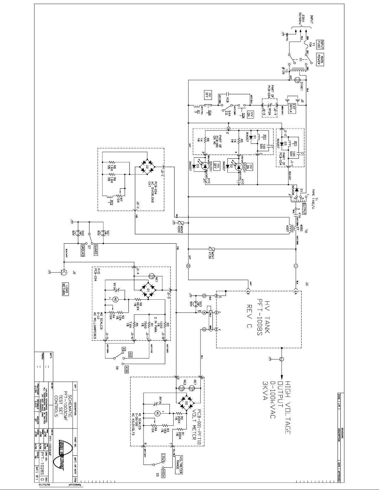
Schematic # PFT-1028S
REF. QUAN HVI# DESCRIPTION
CAB 1 32-033 CABINET, PORTABLE TRANSIT ENCLOSURE. CHARCOAL GRAY.18W x 10D x 14 H ID
D1 1 04-030 DIODE, 1N5408A
D2,3 2 04-025 DIODE, 1N4007A
F1 1 06-038 FUSE, 10A, 250V, AGC-10
1 06-015 FUSE HOLDER, LITTELFUSE # 342004A
J2 1 07-440 CONNECTOR, BULKHEAD, 2 SOCKET, CINCH #S302AB
J3 1 CONNECTOR, BULKHEAD, CIRCULAR, PART OF HIGH VOLTAGE TANK
J4 1 07-206 CONNECTOR, BULKHEAD, BNC, AMPHENOL # UG1094A/U
K1 1 11-150 CONTACTOR, 3PDT , 15A, 120 Vac COIL, MAGNECRAFT # W389ACX-14
M1 1 13-141
M2 1 13-151
MOV1 1 06-207 METAL OXIDE VARISTOR, # V130LA10A
MOV2 1 06-210 METAL OXIDE VARISTOR, # V250LA20A
P1 1 22-205 INPUT POWER CABLE, 16/3, 12 ft.
P2 1 07-442 CONNECTOR, CABLE, 2 CIRCUIT, CINCH# P302CCT
P3 1 07-014 CONNECTOR, CABLE, 7 PIN CIRCULAR, AMPHENOL # 97-3106B-20-15S
PCB-001-PFT10 1 82-275 PRINTED CIRCUIT BOARD, VOLT METER
PCB-034 1 82-274 PRINTED CIRCUIT BOARD, AC OVERLOAD/CURRENT METER
S1 1 10-214 SWITCH, PB, MAINT’D, 250 Vac, 10A, DPST, NO, ISOLATED NEON LAMP, MICROSWITCH
1 10-250 SWITCH, PB COVER, BLACK, MICROSWITCH # AML52-N10K
S2 1 10-222 SWITCH, PB, MOM., 125 Vac, 15A, SPDT, GRN LED, MICROSWITCH # AML22CBS2AA
S3 1 10-218 SWITCH, PB, MOM., 125 Vac, 15A, SPDT, RED LED, MICROSWITCH # AML22CBC2AA
2 10-252 SWITCH, PB COVER, BLACK, MICROSWITCH # AML52-C10K
S4 1 10-106 SWITCH, SNAP ACTION, SHORT ARM, OMRON #A-20GV22-B7-K
S5 1 10-514 SWITCH, ROTARY, 6 POL, 2 POS, MOUSER # 10YX062
S6 1 10-510 SWITCH, ROTARY, 4 POL, 3 POS, MOUSER # 10WW043
S7 1 10-402 SWITCH, ROCKER, DPDT, CARLINGSWITCH # 62115929-0-0-V
SG1-3 3 06-205 SPARK GAP, 90V, CP CLARE, CG90L
T1 1 25-108 TRANSFORMER, VARIABLE, SUPERIOR TYPE 116
T2 1 T080 TRANSFORMER, CURRENT, HVI #080
T3 1 T139 TRANSFORMER, AUTO STEP-DOWN, HVI#139
HV TNK 1 TANK, HIGH VOLTAGE 100 kVac , HV # PFT-1008S REV C
PCB-001-
PFT10
C1 1 03-060
D1 1 04-025 DIODE, 1N4007A
D2 1 04-415 DIODE, FULL WAVE BRIDGE, 1.5A, 1kVdc, MOUSER # 583-RB157
J1 1 07-136 CONNECTOR, HEADER, 8 PIN, .1” SPACING, MOLEX # 22-23-2081
NE1,2 2 15-114 NEON LAMP, #NE2
P1 1 07-120 CONNECTOR, CABLE, 8 PIN, .1” SPACING, MOLEX # 22-01-2087
PCB 1 14-001 PRINTED CIRCUIT BOARD, HVI # PCB- 001
82-275 VOLT METER PCB
8 07-104 CONNECTOR PINS, .1” SPACING, MOLEX # 08-50-0114
METER, ANALOG, 100 µA MOVEMENT, SCALED 0-50/100 AC KILOVOLTS
METER, ANALOG, 100 µA MOVEMENT, SCALED 0-1.0 AC MILLIAMPERES
#AML32FBB4AD
CAPACITOR, ELECTROLYTIC, RADIAL LEADS, 100µF, 50 Vdc, MOUSER # 140-XRL50V100
Saved 10/7/2008 9:13:00 AM, T:\PRODUCT\DOCUMENTS\Manuals\PFT\pl_pft1003CMF_2k8Rg.doc
Page 1 of 3
Page 25

R1,2 2 01-154 RESISTOR, METAL FILM, 0.25W, 200K, 1%
R3 1 01-114 RESISTOR, METAL FILM, 0.25W, 18K, 1%
R4 1 02-018 RESISTOR, POTENTIOMETER, 0.25W, 10K, MOUSER # 569-25PR-10K
R5,6 2 01-310 RESISTOR, CARBON FILM, 1W, 1K, 5%
RY1 1 11-110 RELAY, PCB MOUNT, SPDT, 24 Vdc COIL, P&B # T70L5D131-24
PCB-034
C1 1 03-060
D1,2 2 04-415 DIODE, FULL WAVE BRIDGE, 1.5A, 1kVdc, MOUSER # 583-RB157
D3 1 04-025 DIODE, 1N4007A
J1 1 07-136 CONNECTOR, HEADER, 8 PIN, .1” SPACING, MOLEX # 22-23-2081
J2 1 07-130 CONNECTOR, HEADER, 5 PIN, .1”SPACING, MOLEX # 22-23-2051
NE1 1 15-114 NEON LAMP, #NE2
P1 1 07-120 CONNECTOR, CABLE, 8 PIN, .1”SPACING, MOLEX # 22-01-2087
P2 1 07-114 CONNECTOR, CABLE, 5 PIN, .1”SPACING, MOLEX # 22-01-2057
PCB 1 14-034 PRINTED CIRCUIT BOARD, HVI # PCB-034
R1 1 01-054
R2 1 01-092 RESISTOR, METAL FILM, 0.25W, 5.9K, 1%
R3 2 01-214
R4,7 2 02-018 RESISTOR, POTENTIOMETER, 0.25W, 10K, MOUSER # 569-25PR-10K
R5 1 01-098 RESISTOR, METAL FILM, 0.25W, 7.68K, 1%
R6 1 01-138 RESISTOR, METAL FILM, 0.25W, 49.9K, 1%
R8,9 2 01-312 RESISTOR, CARBON FILM, 1W, 1.6K OHM, 5%
RY1,2 2 11-140 RELAY, PCB MOUNT, SPDT, 24 Vdc COIL, P&B # T70L5D131-24
MISC.
1 23-101 KNOB, SKIRTED, DIAL, MOUSER # 45KN021
2 23-101 KNOB, SKIRTED, POINTER, ALCO # PKD-70B-1/4
1 BRACKET, ZERO START, HVI # BKT-1003D
1 88-002 TEST LEAD, GROUND, BLACK, 20 FT. WITH CLIP AND BOOT
1 88-006 SHIELDED RETURN LEAD, 10 FT. RG58/U WITH CONNECTOR AND CLIP
20 ft. 22-607 CABLE, COMPOSITE, 3/12 AWG, 3 SHIELDED,
1 08-891 TERMINAL BLOCK, 5 POS., # 5-141
1 34-215 U-WRAP, HVI # PFT-1001D,
1 34-118 PANEL, CONTROL, HVI # PFT-1102D
HV TANK
J1 1 07-010 CONNECTOR, BULKHEAD, CIRCULAR, AMPHENOL # 97-3102E-20-15P
R1-4 1 01-440 RESISTOR, METAL FILM, 12.5W, 60M, 1%, EBG # SSX103-60M
T1 1 T108 TRANSFORMER, HIGH VOLTAGE, HVI # 108
T2 1 T108T TRANSFORMER, HIGH VOLTAGE, HVI # 108 W/ TERT
1 08-819 TOROID, ALUMINUM, 13 x 2 INCH
1 40-613 FIBERGLASS CYLINDER, 8.25 I.D. x 20 INCH LONG
1 34-052 BASE ASSEMBLY, HVI # PFT-1012D
X1,2 2 09-120 TERMINALS, FEEDTHROUGH, 10-32 THREAD, LUNDEY # 375-T20
X3,4 2 09-100 TERMINALS, FEEDTHROUGH, 6-32 THREAD, LUNDEY # 250-S-T-15
82-274
12 07-104 CONNECTOR, CRIMP PIN, .1”SPACING, MOLEX # 08-05-114
84-240 PFT-1003 HIGH VOLTAGE TANK, SCHEMATIC # PFT-1008S REV C
AC OVERLOAD/CURRENT METER
CAPACITOR, ELECTROLYTIC, RADIAL LEADS, 100µF, 50 Vdc, MOUSER # 140-XRL50V100
RESISTOR, METAL FILM, 0.25W, 750Ω, 1%
RESISTOR, METAL FILM, 0.5W, 133Ω, 1%
Saved 10/7/2008 9:13:00 AM, T:\PRODUCT\DOCUMENTS\Manuals\PFT\pl_pft1003CMF_2k8Rg.doc
Page 2 of 3
Page 26

SPECIFICATIONS
Input 230 V, 10 amps, 50/60Hz, single phase
HV Output 0-100 kVac, 1.0KVA resistive load
Output
Termination
Duty 3KVA: 1 hour ON, 1 hour OFF
Distortion <5%
Meter
Accuracy
Kilovoltmeter 3.5 inch
PFT-1003CMF
Part No. PFT-1028S
3KVA capacitive load
Top Toroid
1.5KVA: continuous
+/-2%
Scaled 0-50/100kVac (RMS)
Current Meter
Case Size
H.V. TANK
Weight CONTROL-55 lbs. (25kg)
Scaled 0-1.0 milliamperes with x1, x10, x100 range multiplier
3.5 inch
19w x 11d x 15.5 high
12w x 13d x 24 high
HV TANK-82 lbs. (38kg)
Table 1 PFT-1003CMF Specifications.
Saved 10/7/2008 9:13:00 AM, T:\PRODUCT\DOCUMENTS\Manuals\PFT\pl_pft1003CMF_2k8Rg.doc
Page 3 of 3
Page 27
Page 28
Page 29
 Loading...