

High Voltage DTS-60A Operator's Manual

DTS-60A
Dielectric Oil Test Set
Operator’s Manual
Version 1.20
HighVoltage
INC
.

DTS-60A OPERATORS MANUAL
All rights reserved. Total or partial reproduction of this manual, whether by printed or
electronic means, is forbidden. Information regarding any errors found in it or suggestions
concerning improvement are appreciated. Since products are subject to continuous check
and improvement, High Voltage inc. reserves the right to make changes in information
contained in this manual without prior notification.
Manual Revision 07/03/2008 Version 1.20
Copyright 2005 High Voltage inc. – USA
HIGH VOLTAGE, INC.
31 County Route 7A
Copake, N.Y. 12516
Phone : 518/329-3275
Fax : 518/329-3271
Web :
e-mail: Factory@hvinc.com
http://www.hvinc.com

DTS-60A OPERATORS MANUAL
DTS-60A OPERATORS MANUAL
Icons & Notation
This icon indicates danger conditions!
Danger!
This icon indicates warnings!
Warning!
Note!
This icon indicates a hint or a tip!

DTS-60A OPERATORS MANUAL
DTS-60A OPERATORS MANUAL
This Operator manual contains instructions
for the operation of a High Voltage power
source. The operator of this equipment must
use good judgement and follow all safety
precautions noted in this guide to ensure the
protection of himself and others in close
proximity to the test area. Failure to follow
the instruction could result in injury or
death.
Proper grounding of the test set must be
done prior to connecting this unit to a power
source.

DTS-60A OPERATORS MANUAL

DTS-60A OPERATORS MANUAL
Table of Contents
1. Specifications and Controls
1. Features and Specifications
2. Control Panel
3. User Interface
1. Menu Overview
2. Keyboard Operations
3. Warning Messages
4. Question Messages
5. Error Messages
6. Indicators
4. Setup the Equipment
5. Using the Shielded Output Cables
6. Startup the Equipment
2. Menu/ Submenus and Settings
1.
Main Menu Overview
2. Main Menu
3. Programs Submenu
4. Settings Submenu
1. Time/Date Setup
2. Operator Setup
3. LCD Contrast Setup
4. Language Setup
5. Region Setup
3. Simple Test
1. Simple Test Operations
2. Simple Test Initialization
3. Simple Test Execution
4. Simple Test Termination
5. Simple Test Example
4. Standard Tests
1. Standard Test Description
2. Select a Standard Test
3. Standard Test Execution
4. Standard Test Example

DTS-60A OPERATORS MANUAL
5. User Defined Tests
1. Test Description
1. Test Structure
2. Test Operations
2. Test Menu
1. Select Test
2. Create Test
3. Edit Test
4. Delete Test
3. Script Files for Tests
1. Script File Commands and Arguments
2. Script File Test Example
6. History and Results
1. +++
2. +++
7. Printer and Printouts
1. Printer Description
2. Changing the Paper Roll
3. Printout Description
8. Remote Operation
1. Enable the Remote Operation
2. Ver Command
3. cls Command
4. time Command
5. date Command
6. operator Command
7. contrast Command
8. program Command
1. program list Command
2. program read Command
3. program delete Command
4. program download Command
9. history Command
Care and Maintenance
Appendix I Standard Test Script Files
Appendix II Firmware Upgrade Procedure
Acronyms & Abbreviations
Index


DTS-60A OPERATORS MANUAL
1. Features and Specifications 1-2
2. Control Panel
3. User Interface
4. Setup the Equipment
5. Using the Shielded Output Cables 1-15
6. Startup the Equipment
1
Specifications and Controls
This section familiarizes the operator with the features and the
specifications of the DTS-60A AC Dielectric Oil Test Set manufactured
by High Voltage, inc. Moreover, a brief introduction about the
equipment’s set-up and start-up is presented.
1-4
1-5
1. Menu Overview 1-5
2. Keyboard Operations 1-6
3. Warning Messages 1-8
4. Question Messages 1-10
5. Error Messages 1-12
6. Indicators 1-13
1-14
1-16
1

DTS-60A OPERATORS MANUAL
1.1 Features and Specifications
The DTS-60A AC Dielectric Oil Test Set provides automatic,
programmable and accurate measurement of breakdown voltage for
insulating oils used in high-voltage electrical equipment.
Main features of the DTS-60A Series of AC Dielectric Oil Test Set
User Interface
Dot Matrix Liquid Crystal Display (128x64)
Compact 5-key keyboard for operation
User friendly, menu driven functionalities
Large Output Voltage Digits (3.1 digits)
Functionalities
Test-Result report
Real-Time clock
Ambient Temperature measurement
International Standard Tests
User defined Tests
Test-Results storage
Language selection
Measurements and Control
High accuracy of High Voltage measurement (0.5%)
Digitally selected Voltage rate of rise (0.1kV/s step)
Arc detection with less than 5 milliseconds shutdown
Digital Closed-Loop for voltage control
Equipment Case
Rugged aluminum case
Window for observation of oil test
2

DTS-60A OPERATORS MANUAL
Table 1.1 - Specifications
DTS – 60A
Input 120V, 50/60 Hz, 5 amps, single phase
230V, 50/60 Hz, 3 amps, single phase
Output 0 – 60kVac, 800VA resistive load, between bushings
Output Termination Dual Capacitively Graded Bushings
Display Dot-Matrix 128x64
Keyboard 5 keys for equipment’s functionalities
Printer Optional 40 columns dot-matrix
Remote Management RS-232 Serial Interface
Breakdown Shutdown Less than 5 ms
Accuracy 0.5%
Operating
Temperature
Case Size 14.75w x 14d x 11.5h in (36.88w x 35d x 28.75h mm)
H.V. Tank High Voltage Tank Included
Weight 60 lbs.
-14 F to 104 F (-10 C to 40 C)
3
DTS-60A OPERATORS MANUAL
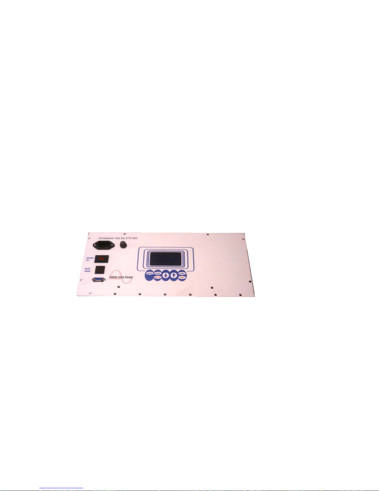
1.2 Control Panel
The equipment’s Control Panel is depicted in Figure 1.1. It
consists of the following:
Input Power
The Input Power connector accepts most standard
electrical equipment type cords. The power supplied to
the input connector must be from a grounded source
rated to match the input power specifications noted in
Table 1.1.
Main Power
The Main Power switch provides the power to the
control and power circuits. The neon lamp will light
when the power is on and the voltage is available
through the input line cord. The Input Power Fuse
located electrically before the Main Power switch
provides line fault protection for the unit.
Fuse Socket
LCD display
The Liquid Crystal Display guides the user to the
system’s functionalities.
Keyboard
Compact 5-key keyboard for equipment operation.
Figure 1.1 – DTS-60A Control Panel
4
DTS-60A OPERATORS MANUAL
1.3 User Interface
The equipment User Interface is based on a dot-matrix Liquid
Crystal display (LCD) and a compact 5-key keyboard, Figure 1.2. The
user-friendly graphical interface makes the equipment's operation
simple and attractive.
Figure 1.2 – Equipments User Interface
1.3.1 Menu Overview
The equipment operation is based on a user friendly structure of
menu/ submenu driven functions. An overview of the menu/
submenu selections is summarized in Figure 1.3.
MENU
TESTS
SETTINGS
TEST HISTORY
REMOTE OPERATION
TESTS
SELECT
CREATE
EDIT
DELETE
SETTINGS
TIME/DATE
OPERATOR
LCD CONTRAST
LANGUAGE
REGION SETUP REGION APP
Figure 1.3 – Equipment's User Interface
SELECT TEST APP
CREATE TEST APP
EDIT TEST APP
DELETE TEST APP
SETUP TIME/DATE APP
SETUP OPERATOR APP
SETUP LCD CONT. APP
SETUP LANGUAGE APP
TEST HISTORY APP
REMOTE OPERATION APP
5

DTS-60A OPERATORS MANUAL
1.3.2 Keyboard Operations
Although most of the keyboard operations are based on similar
methods, there are some cases where an optional key functionality is
enabled. These exceptions are described analytically in the
respective manual paragraphs.
The most common keyboard operations are the following:
Menu and Submenu Operations
MENU Enter to the Menu or Selected Submenu
BACK Exit from Menu or Current Submenu
UP Go to the previous selection
DOWN Go to the next selection
ENTER Enter to the selection
Simple Test Operations
MENU Enter to the Menu or Selected Submenu
BACK Enable/ Disable Stirrer
UP Increase Voltage Rate of Rise
DOWN Decrease Voltage Rate of Rise
ENTER Execute Test
ANY After Starting the Test ANY key interrupts the
process
Number Edit Operations
MENU -
BACK Discard changes and return
UP Increase the current value
DOWN Decrease the current value
ENTER Enter the value
String Edit Operations
MENU Select Capitals, Smalls, Numbers, Symbols
BACK Delete Character
UP Select previous character
DOWN Select next character
ENTER Enter the string
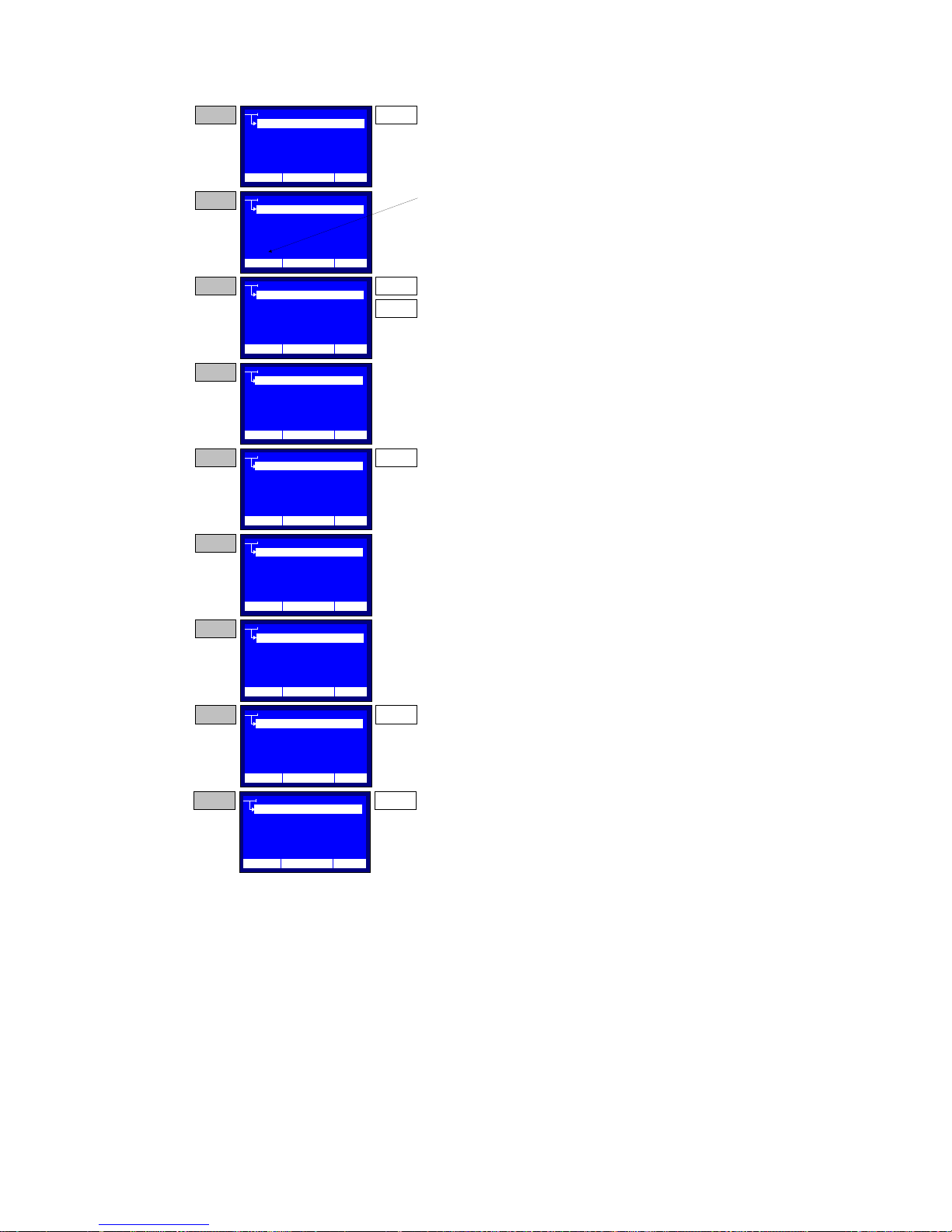
A detailed example follows, Figure 1.4, in order to clarify the
String Edit keyboard operation. The example refers to a string entry
for the Name of the Operator Setup menu (see paragraph 2.3.2).
6
DTS-60A OPERATORS MANUAL
STEP 1
STEP 2
STEP 3
STEP 4
STEP 5
STEP 6
STEP 7
STEP 8
STEP 9 ENTER
OPERATOR
COMPANY
NAME
CONTACT INFO
OTHER INFO
12:10 01/08/04 25 C
OPERATOR
COMPANY
NAME
CONTACT INFO
OTHER INFO
_
12:10 01/08/04 25 C
OPERATOR
COMPANY
NAME
CONTACT INFO
OTHER INFO
O
12:10 01/08/04 25 C
OPERATOR
COMPANY
NAME
CONTACT INFO
OTHER INFO
O_
12:10 01/08/04 25 C
OPERATOR
COMPANY
NAME
CONTACT INFO
OTHER INFO
_
12:10 01/08/04 25 C
OPERATOR
COMPANY
NAME
CONTACT INFO
OTHER INFO
P_
12:10 01/08/04 25 C
OPERATOR
COMPANY
NAME
CONTACT INFO
OTHER INFO
PETER_
12:10 01/08/04 25 C
OPERATOR
COMPANY
NAME
CONTACT INFO
OTHER INFO
PETER_0
12:10 01/08/04 25 C
OPERATOR
COMPANY
NAME
CONTACT INFO
OTHER INFO
PETER_007
12:10 01/08/04 25 C
Press the ENTER key in order to enabl e the String
ENTER
Entry key board operation for the Name
The String Ent ry Cursor is displayed. This
indic ates the current possi tion of the editable
character.
Use the UP and DOW N k eys to select the desi red
UP
character. Dont leave more than 2 seconds
between key pressi ngs. After every UP key
DOWN
pressing the next character of the alphabet wil l be
displ ayed. In contrast, after every DOWN key
pressing the previous c haracter of the alphabet wil l
be displ ayed. The charac ter sequenc y is circ ular.
Stop pressing the UP and DOWN keys for more
than 2 seconds. The character will be entered and
the cursor will be di splay ed in the nex t possition.
A mistak e occured! Press t he B ACK Key i n order
BACK
to delet e the las t entri ed charact er.
Selec t the correct character acc ording STEP 3
instruct ions. Then wait 2 seconds, unt il the cursor
is di splay ed at the next pos sit ion.
Repeat the c haracter entry operat i on for the whole
string.
Press the ME NU key twice, i n order to enter
MENU
numbers in the st ring.
Press the ENTER key in order to enter the edited
sting and return.
Figure 1.4 – String Entry Keyboard Operation
7
DTS-60A OPERATORS MANUAL
1.3.3 Warning Messages
Display shows Warning Messages in the following cases.
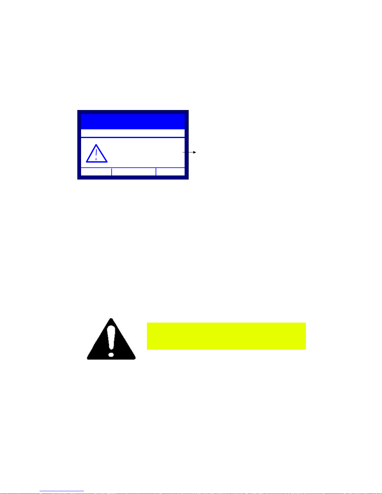
1. Lid is Open, Figure 1.5.
This warning message is displayed when the Lid of the
equipment is open and a test procedure is enabled. The
current operation (i.e. test execution) will be restarted when
the lid will close.
PROGRAM : ASTM-D1816
DURATION: 00:00:00
SYSTEM HALTED...
Lid is Open
12:10 01/08/05 65 °F
Figure 1.5 – ‘Lid is open' Warning Message
If the Warning Message “Lid is Open” is
depicted when the Lid is closed, contact
the distributor or the manufacturer.
Warning Message
8
DTS-60A OPERATORS MANUAL
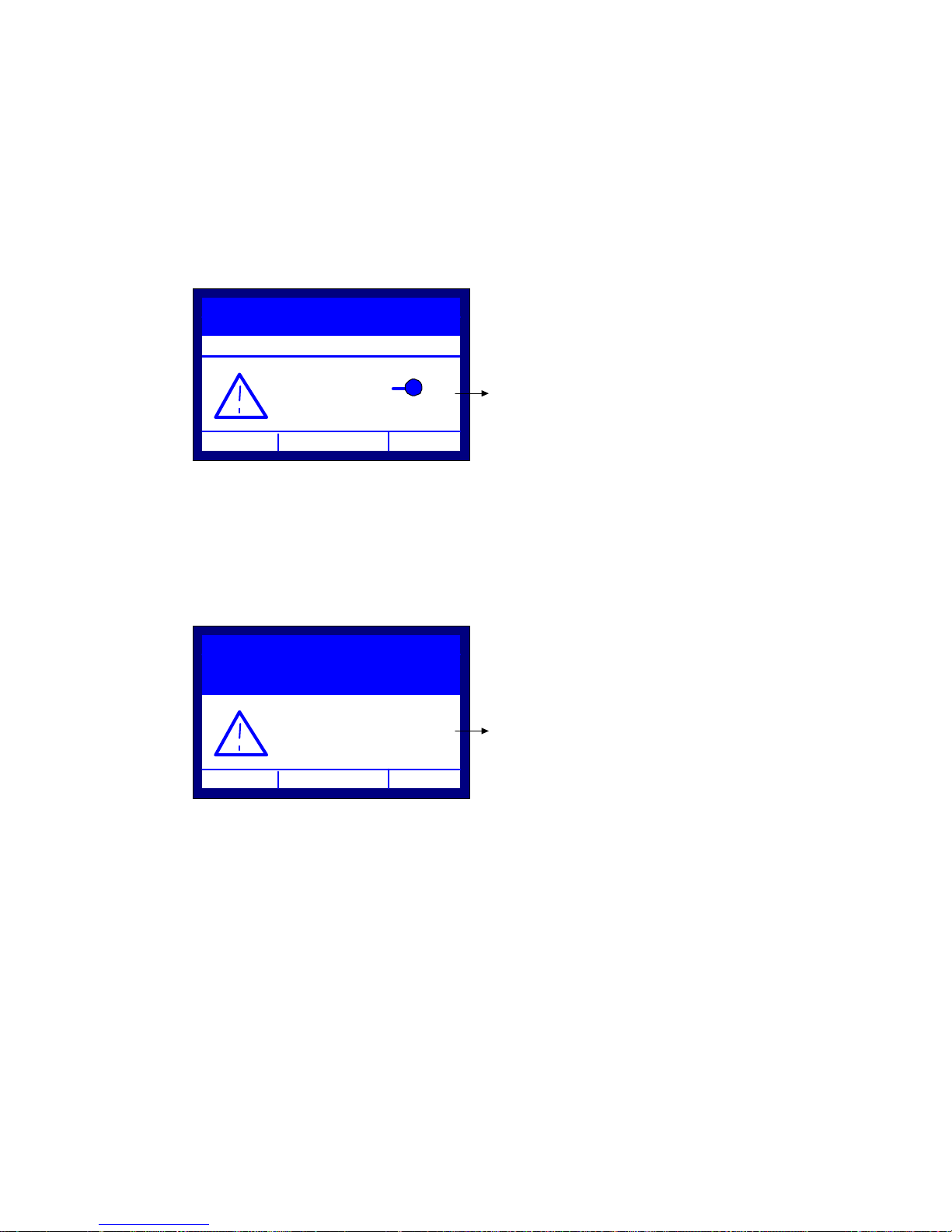
2. Verify Electrode/Gap Spacing, Figure 1.6a/b.
This warning message is displayed at the startup of every
test procedure, in order to remind the user to check the
electrodes type and spacing, according to the selected test.
If the selected test is a standard one (where the spacing
and the type of the electrodes is specific) the message will
inform the user for the appropriate settings (type, spacing),
Figure 1.6a. The user may release the system by pressing
the ‘ENTER’ key.
PROGRAM : ASTM-D1816
DURATION: 00:00:00
SYSTEM HALTED...
Electrodes:
Warning Message
Space: 0.04±0.0010in
12:10 01/08/05 65 °F
Figure 1.6a – ’Electrodes/ Space’ Warning Message
If the selected test is the Simple Test (where the
spacing and the type of the electrodes is not specific) the
message will prompt the user for verification of the desired
electrode type and spacing, Figure 1.6b. The user may
proceed by pressing the ‘ENTER’ key.
PROGRAM: SIMPLE TEST
VOLTAGE: 0.5 kV/s
DURATION: 00:00:00
Verify Elec trodes &
Gap Spacing
12:10 01/08/05 65 °F
Figure 1.6b – Verify Electrode/Gap Spacing’ Warning Message
Warning Message
9
DTS-60A OPERATORS MANUAL
1.3.4 Question Messages
The unit may display the following Question Messages.
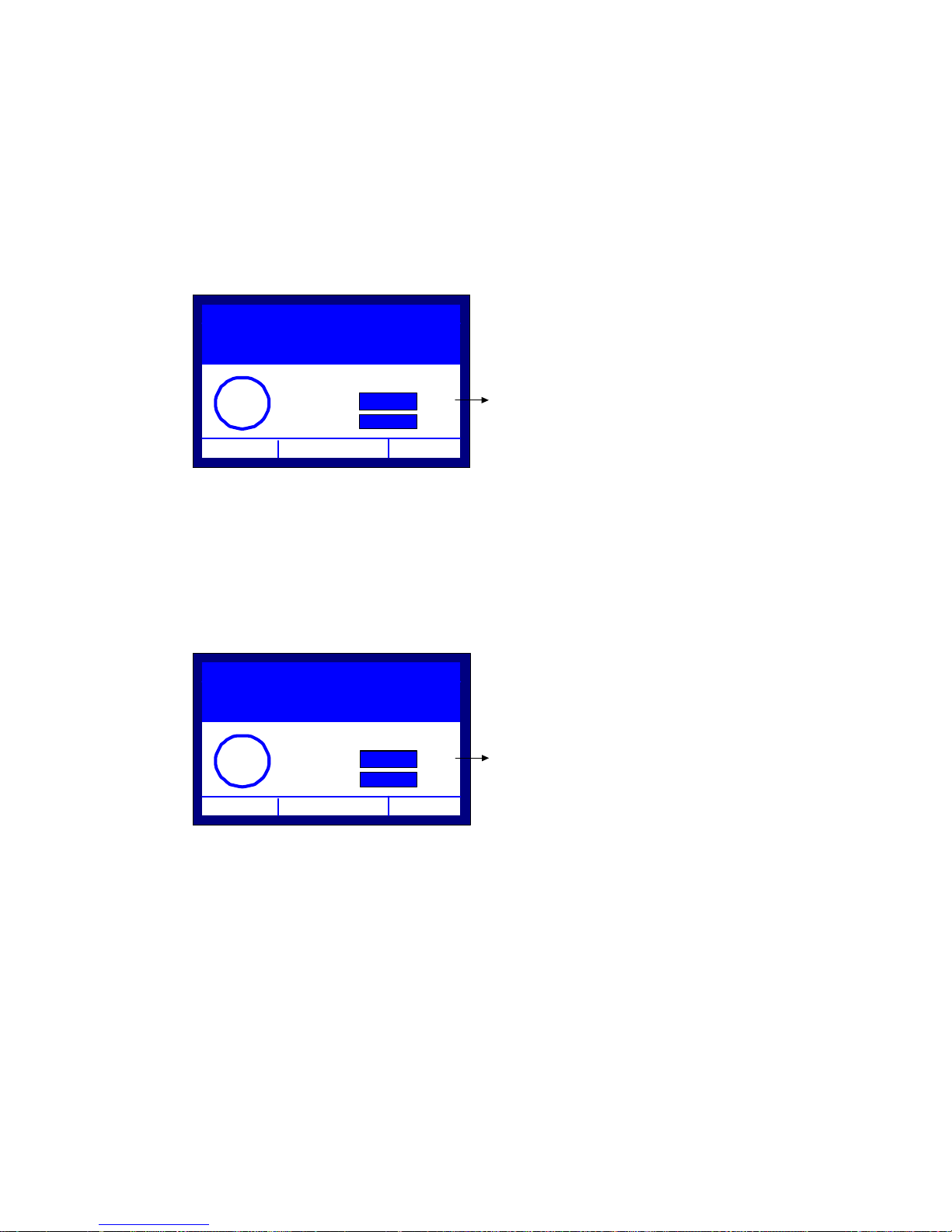
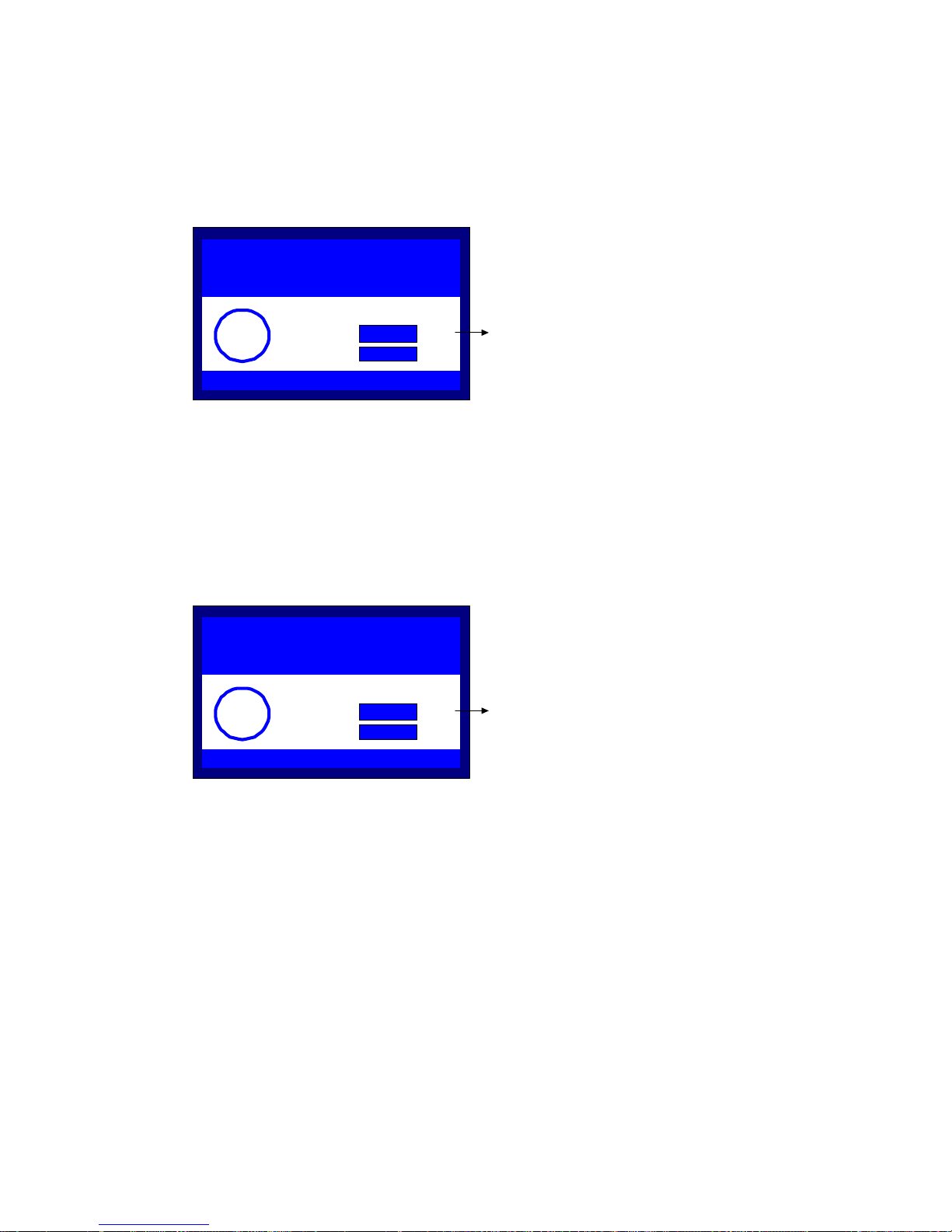
1. Continue Test?, Figure 1.7.
This question message is displayed after a breakdown
detection in the Simple Test procedure. The system
prompts the user for continuing the current test with a new
stage, or terminating the test. User may press the ‘ENTER’
key for continuing the test, or the ‘BACK’ key for
terminating the test. All other keys are disabled.
PROGRAM: SIMPLE TEST
VOLTAGE: 0.5 kV/s
DURATION: 00:00:30
Continue Test?
?
Yes:
No:
12:10 01/08/05 65 °F
Figure 1.7 – ‘Continue Test?’ Question Message
ENTER
BACK
2. Print Results?, Figure 1.8.
This question message is displayed only if the equipment
has a printer. The message prompts the user for printing
the test report after a test is finished. User may press the
‘ENTER’ key for printing the test report, or the ‘BACK’ key
for discarding the printing. All other keys are disabled.
Question M ess age
PROGRAM: SIMPLE TEST
VOLTAGE: 0.5 kV/s
DURATION: 00:00:30
Print Results?
?
Yes:
No:
ENTER
BACK
12:10 01/08/05 65 °F
Figure 1.8 – ‘Print Results?’ Question Message
Question M essag e
10
DTS-60A OPERATORS MANUAL
3. Save Program?, Figure 1.9.
This question message is displayed in the Edit/Create Test
procedure. After the user had edited the test, the system
prompts for saving the program changes. User may press
the ‘ENTER’ key for saving the test, or the ‘BACK’ key for
discarding the changes. All other keys are disabled.
Save Program?
?
Figure 1.9 – ‘Save Program?’ Question Message
Yes:
No:
ENTER
BACK
4. Save Stage Data?, Figure 1.10.
This question message is displayed in the Edit/Create Test
procedure. After the user had edited a stage of a test the
system prompts for saving the stage changes. User may
press the ‘ENTER’ key for saving the stage of the test, or
the ‘BACK’ key for discarding the changes. All other keys are
disabled.
Question M ess age
Save Stage Dat a?
?
Figure 1.10 – ‘Save Stage Data?’ Question Message
Yes:
No:
ENTER
BACK
Question M ess age
11
DTS-60A OPERATORS MANUAL
1.3.5 Error Messages
can display the following Error Code/Messages, Figure 1.11:
Error messages indicate serious equipment malfunction. The system
Error 100, Error 101, Error 102, Error 110, Error 111
Error 112, Error 113, Error 120, Error 121,Error 122
ERROR: 102
Contact
High Voltage Inc.
for m or e inf or m ation.. .
+1 518-329- 3275
12:10 01/08/05 65 °F
Figure 1.11 – Error Message
Whenever you see an ERROR message,
contact with the service or the
distributor.
Error Code
Error Message
User Int er face H elp Message
12
DTS-60A OPERATORS MANUAL
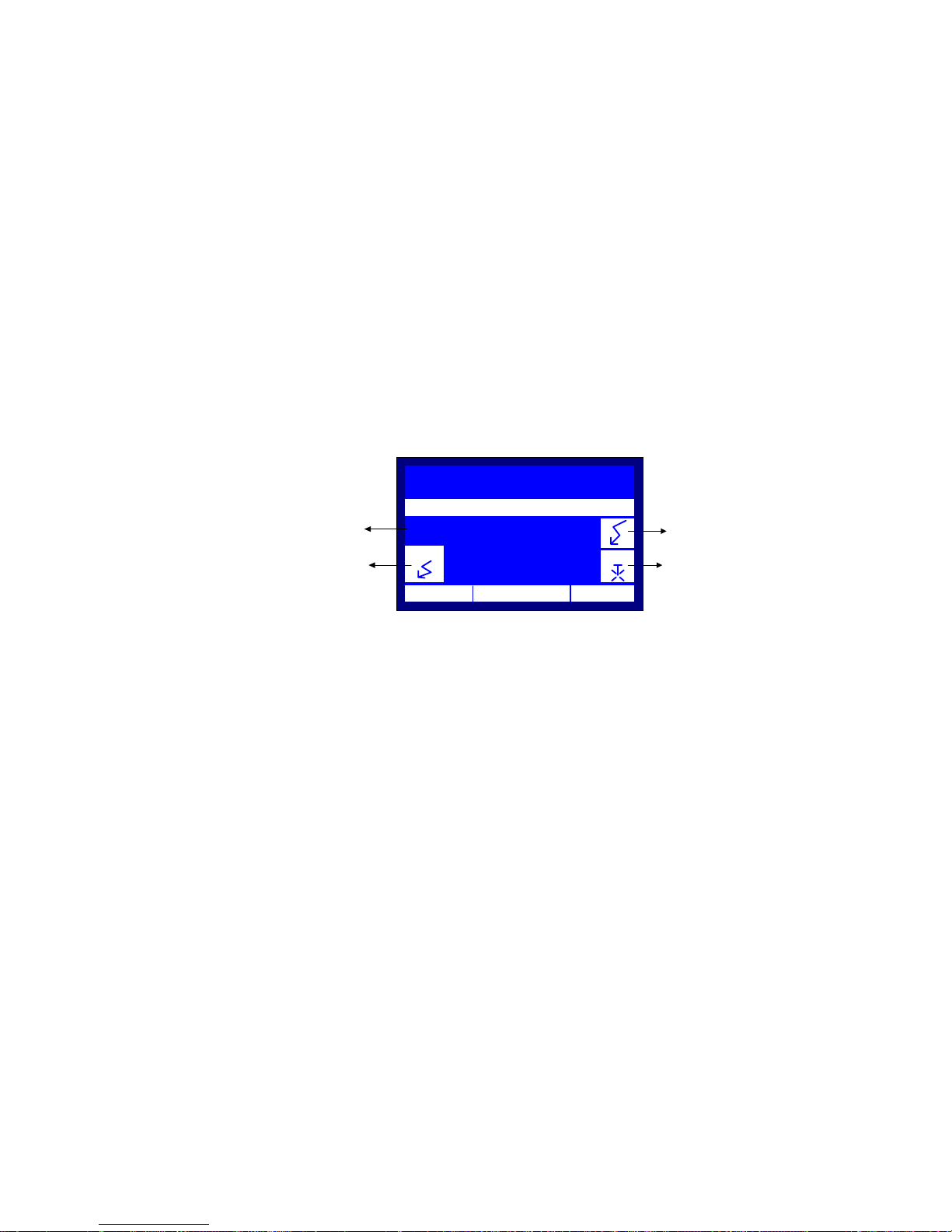
1.3.6 Indicators
Current Stage Indicator
Display shows the following Indicators, in the following cases,
Figure 1.12.
1. Current Stage Indicator
This indicator notifies the user for the current stage of a
test procedure.
2. HighVoltage On/Off Indicator
This indicator notifies the user for the status of the high
voltage tank. If the indicator is displayed, the high voltage
is ON.
3. Stirrer Indicator
This indicator notifies the user for the status of the stirrer.
If the indicator is displayed the stirrer is ON.
4. Breakdown Blinking Indicator
During a test procedure, this blinking indicator notifies the
user for a breakdown detection.
PROGRAM:ASTM-D1816
DURATION:
STARTUP WAIT TIMER...
STAGE
1
HV ON
12:10 01/08/05 65 °F
00:00:00
0.0
kV
STIR
BreakDown Blinking Indicator
Stirrer on/off indicatorHigh Voltage On/Off Indicator
Figure 1.12 – Indicators
13

DTS-60A OPERATORS MANUAL
1.4 Setup the Equipment
The setup of this equipment has been minimized by careful
consideration of the operator during design. The DTS-60xx one-piece
construction permits convenient portability. The DTS-60xx test set
requires that the unit is operated with the control panel in the
horizontal position, to keep oil level over high voltage transformer in
the high voltage tank.
1. Select a location for the unit that will allow easy
viewing of the User Interface
2. Be sure that all the controls are off, in their deenergized state.
3. Remove all components and oil vessels from the test
chamber
4. Install the input line cord into the Input Power
receptacle
5. Connect the line cord to a suitable (120V or 230V,
see Specifications Table) grounded power source.
6. Select the desired Test cell. Fill in with sufficient
insulating liquid for the testing to be performed.
7. Clean the Test Cell and Electrodes thoroughly and
adjust the electrodes to conform with the proper ASTM
Specification. Be sure the electrodes are securely
tightened on the adjustment posts inside the oil vessel.
Use Isolation transformer (1/1) if the
electrical installation has neutral
earthing.
All the oil vessels designed and made by High
Voltage Inc.
have interchangeable posts and electrodes. These
oil
vessels were designed to conform to the ASTM test
14
DTS-60A OPERATORS MANUAL
specifications requiring simple disassembly for
cleaning.
This design greatly reduces the time and effort
required
keeping your oil vessels in top operating condition.
The operator of this equipment must
use good judgement and follow all
safety precautions noted in this guide
to ensure the protection of himself and
others in close proximity to the test
area. Failure to follow the instruction
could result in injury or death.
15
DTS-60A OPERATORS MANUAL
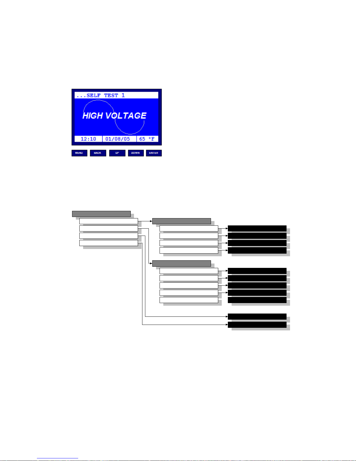
1.6 Startup the Equipment
1. Ensure that setup has been completed as noted in
2. Turn on Main Power.
3. The equipment initiates a self-test, Figure 1.13. In case of
...SELF TEST 1
HIGH VOLTAGE
12:10 01/08/05 65 °F
paragraph Setup the equipment (1.4).
malfunction, an error message (see paragraph 1.3.4) is
displayed and the system will be halted.
TM
INC
MENU BACK
Figure 1.13 – Startup and Self Test
DOWNUP
ENTER
4. After the self-tests are completed, the unit proceeds with
the last selected test (Simple Test, Standard or UserDefined).
5. The unit will display the Electrode Warning message (see
paragraph 1.3.3) and it will wait for ‘ENTER’ to be pressed.
6. The user may open the lid, check the electrodes (type and
spacing) and finally fill the appropriate test vessel with
insulating oil.
7. After closing the lid, the user should press the ‘ENTER’ key
in order to initiate the test procedure.
Whenever you see an ERROR message
contact with the service or the
distributor.
16

DTS-60A OPERATORS MANUAL
2
This section describes the equipment’s Menus and Submenus. The
interface supports a simple menu/submenu structure in order to provide
user- friendly operation.
1. Menu Operation Overview 2-2
2. Main Menu 2-3
3. Test Submenu 2-4
4. Settings Submenu 2-5
1. Time/Date Setup 2-6
2. Operator Setup 2-7
3. LCD Contrast Setup 2-8
4. Languages Setup 2-9
5. Region Setup 2-10
Menu/ Submenus
and Settings
17

DTS-60A OPERATORS MANUAL
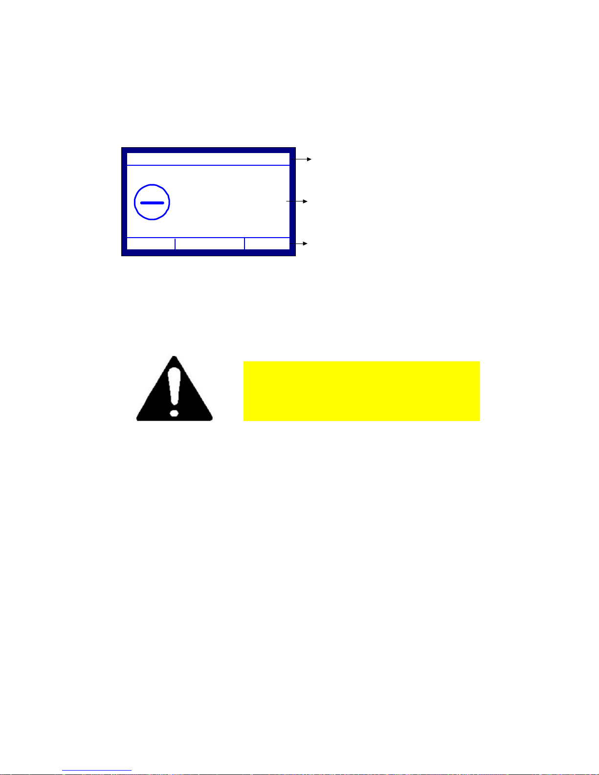
2.1 Menu Operation Overview
In every menu/submenu screen, the first line indicates the title and the
following lines indicate the possible selections, Figure 2-1. The guide uses a
selector for pointing to the current selection and the selection title becomes
inverted. The keyboard usage is very simple with the ‘’, ‘’, ‘BACK’ and
‘ENTER’ keys:
BACK Exit from Menu or Current Submenu
(UP) Go to the previous selection
(DOWN) Go to the next selection
ENTER Enter to the selection
Finally, the last line indicates the current time and date, as well as the
temperature.
MENU TITLE
MENU ITEM #1
MENU ITEM #2
MENU ITEM #3
MENU ITEM #4
MENU ITEM #5
12:10 01/08/05 65 °F
Figure 2.1 – Menu Setup
FirstLine Displays the MENU TITLE
Following Lines Display the MENU ITEMS
Last Line Displays the TIME/DATE/TEMP.
18

DTS-60A OPERATORS MANUAL
2.2 Main Menu
The possible selections are the following:
The Main Menu is displayed by pressing the ‘MENU’ key, Figure 2.2.
Test
Go to the Test Submenu. The latter includes all the test
functionalities, such as select a test for execution, edit a test, etc.
Settings
Go to the System Settings Submenu. The latter includes the basic
system settings, which are the Time/Date setup, Printout setup,
LCD Contrast setup and the Language setup.
Test History
Run the Results History Application (see section 6). This can be
used for browsing the results of previously executed test programs.
Remote Operation
Run the Remote Operation Application (see section 7). This can be
used as an alternative operation mode, via a common terminal
software running on a Personal Computer.
MENU
PROGRAMS
SYSTEM SETTINGS
TEST HISTORY
REMOTE OPERATION
12:10 01/08/05 65 °F
Figure 2.2 – Main Menu
MENU
BACK
DOWN
UP
ENTER
No operation
Return to test execution application
Move selector down
Move selector up
Enter to the selection
19

DTS-60A OPERATORS MANUAL
2.3 Test Submenu
The Test Submenu is displayed upon the TEST Selection from the Main
Menu, Figure 2.3. The possible selections are the following:
Select
Create
Edit
Delete
Application used for the selection of a test for execution (see
paragraph 4.2.1). The system displays a list of the available tests,
where the user can simply select one and further execute it.
Application used for the creation of a new test (see paragraph
4.2.2). The system uses a simplified interactive method for entering
the details of a test scenario.
Application used for updating an existing test (see paragraph
4.2.2).
Application used for deleting an existing user defined test (see
paragraph 4.2.3). The system displays a list of the available user
defined test programs, where the user can simply select one and
further delete it.
TEST
SELECT
CREATE
EDIT
DELETE
12:10 01/08/05 65 °F
Figure 2.3 – Test Submenu
MENU
BACK
DOWN
UP
ENTER
No operation
Return to MAIN MENU
Move selector down
Move selector up
Enter to the selection
20
 Loading...