

High Sierra Alert IFlows VHF Data Receiver, 4500 User Manual

Model 4500 ALERT/IFLOWS VHF Data Receiver
Instruction Manual 60-4500-01(A)
ABLE OF CONTENTS
T
1.0 Introduction .......................................................................................................1
1.1 General Description: .....................................................................................1
1.2 Receiving, Inspection and Unpacking:........................................................1
1.3 Specifications: ................................................................................................2
2.0 Installation.........................................................................................................2
3.0 Operation...........................................................................................................3
4.0 Radio ..................................................................................................................3
4.1 Frequencies available....................................................................................3
5.0 Maintenance ......................................................................................................4
5.0 Troubleshooting ................................................................................................4
6.0 Returns ...............................................................................................................5
7.0 Warranty............................................................................................................5
8.0 Appendix ...........................................................................................................6
8.1 06-4500-04 Receiver wiring...........................................................................6
8.2 61-4500-82 Maxon Radio user adjustments.................................................7
8.3 61-12209 Receiver Decoder Interconnect:...................................................8
1.0 INTRODUCTION
1.1 General Description:
The Model 4500 ALERT/IFLOWS VHF Data Receiver receives an incoming RF
signal from field transmitters and repeaters then converts this signal to an audio tone
that is then sent to a High Sierra Electronics Model 1000 ALERT/IFLOWS Data Decoder.
The Model 4500 ALERT/IFLOWS VHF Data Receiver is fully automatic requiring no
manual intervention. The receive frequency is set at High Sierra Electronics to customer
specifications. See section 4.1 for factory default selections. Other frequencies are
available on request.
1.2 Receiving, Inspection and Unpacking:
Many High Sierra Electronics products are scientific instruments. Exercise care
during unpacking and installation. Remove the contents of the package carefully and
compare the contents with the enclosed packing list. Should any items be missing,
notify High Sierra Electronics Customer Service. Please have your packing list available
when you call.
Model 4500 April 2004
1

If any of the items are received in damaged condition, immediately notify the
carrier and request an inspection. You must notify the carrier within 15 days of
shipment. If a claim is not made within that time period, then the carrier will not
acknowledge any claim for the lost or damaged goods.
1.3 Specifications:
Receiver
Input: RF, VHF or UHF (Customer specified)
Frequency Range: VHF 135 - 174MHz; UHF 406 - 470MHz
Output: 700 mV
Connector:
1/8
Stereo phone jack
audio signal
p-p
Voltage: ~12 VDC
Current: ~50 mA
Squelch: Open: -112 dBm, Close: -114 dBm
Impedence: 600 Ohm
Temp. Range: -30 to +60° C
Size: 8 1/4" wide x 2" high x 7" deep
Weight: 2 Pounds
Float Charger
Input: 110 VAC 60Hz, 0.11A
Output: 13.7 VDC @ 0.3A
Size: 2.2" x 1.88" x 1.94"
Weight: 0.5 Pounds
2.0 INSTALLATION
The Model 4500 ALERT/IFLOWS VHF Data Receiver is shipped complete, no
additional items are required for installation. The Model 4500 should be located near
the antenna mounting structure so as to minimize losses in the antenna transmission
line and it must be installed in a dry location, protected from inclement weather.
A cable from the jack marked "AUDIO OUT" on the rear of the chassis connects
to the "AUDIO IN" on the Model 1000 Decoder. The audio cable connection to the
decoder may be up to 1000 feet in length. Audio cable in excess of 100 feet should be
inch stereo plug (twisted pair
shielded with tip, ring and shield connections to a
1/8
phone wire may also be used).
The antenna connects to the Model 4500 via a BNC type connector on the rear of
the chassis.
A wall mount float charger and connecting cable is supplied to power the
receiver. Attach this cable to the terminal strip marked 12 VDC IN. Connect the red
spade lug to the left terminal marked "+", and the black wire - spade lug to the
+
wire
right terminal marked "-". In addition, a cable to connect an external gel cell battery is
supplied if an uninterruptible power source is desired. If a gel cell battery is used, the
Model 4500 April 2004
2
float charger will keep the battery charged. NOTE: it is important not to reverse
polarity when connecting power to the Model 4500 Receiver.
In areas subject to electrical storms it is advisable to use a lightning protection
device in the antenna transmission cable to protect the receiver from damage due to
"near hits". During periods of electrical activity the receiver may present a shock
hazard should the antenna be struck by lightning. During these periods it is
recommended that personnel stay clear of the receiver and associated equipment to
reduce the chance of injury due to this hazard.
3.0 OPERATION
The Model 4500 receives frequency modulated RF signals from remote
transmitters and repeaters. These signals are then amplified, demodulated and the
resultant audio signal is sent to the decoder. The audio signal consists of tones having a
frequency of either 2133 Hz or 1920 Hz.
The Green LED on the front panel indicates if power is being supplied to the
receiver and should always be on.
The speaker On-Off switch on the front panel of the Model 4500 allows audio
monitoring of the received signals.
4.0 RADIO
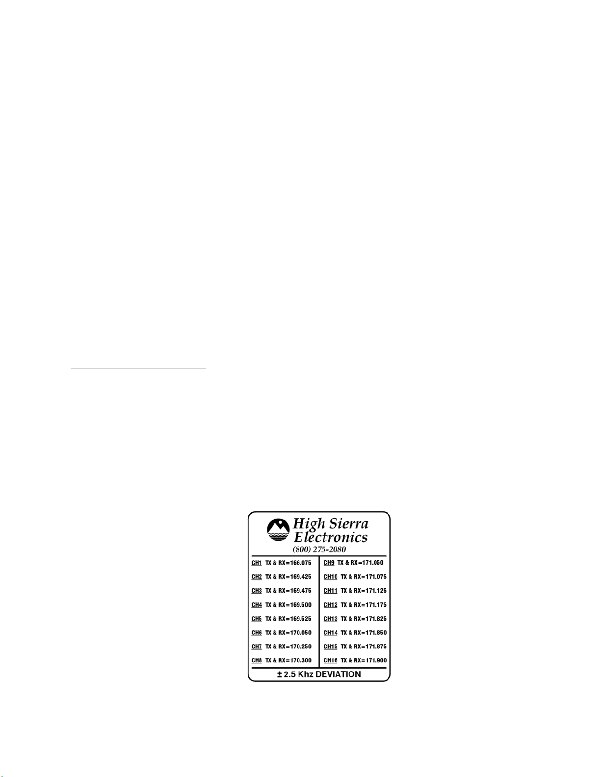
4.1 Frequencies available
If the systems operating frequency is specified, then the radio is preset at the
factory with the selected channel highlighted on the cover. To change or select a
frequency, remove the four screws that secure the transceiver cover. Using the channel
selection guide on the inside of the receiver cover, set the 4-position dip switch to the
required frequency.
Frequency between 148.000 and 174.000 MHz can be programmed into these
radios. The 16-channels factory defaults are commonly used frequencies. UHF
frequencies between 406 - 470MHz are available on request.
Model 4500 April 2004
3
 Loading...