

Page 1
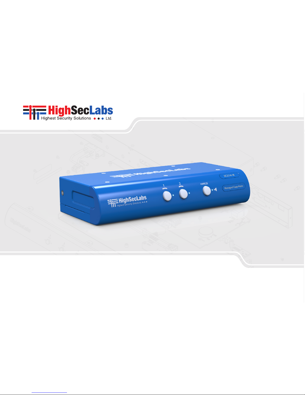
2-Port KVM Combiner
SC21HN | QUICK SETUP GUIDE
Models:
SC21H-N – 2-Port HDMI Video KVM Combiner, PP 3.0
HDC15377 Rev. 1.0
Page 2

1
HSL Secure 2-Port KVM Combiner Quick Setup Guide
TABLE OF CONTENTS
SECTIONS
Table of Contents
1 2 3
Introduction .......................................................... 2
HSL 2-Port KVM Combiner ....................................................2
Installation............................................................ 3
Installing the Combiner . . . . . . . . . . . . . . . . . . . . . . . . . . . . . . . . . . . . . . . . . . . . . . . . . . . . . . .3
Step 1 – Combiner Installation ................................................3
Step 2 – Power ON the Combiner .............................................4
Operation ............................................................. 5
Operating the Combiner ......................................................5
Page 3

2
HSL Secure 2-Port KVM Combiner Quick Setup Guide
INTRODUCTION
SECTIONS
Table of Contents
2 31
HSL 2-Port KVM Combiner
Interact with multiple computers presented on the same display at the
same time using a single set of USB, audio, keyboard, video and mouse
peripherals.
The KVM Combiner switch offered by HSL provides increased
productivity in challenging multi-computer environments where
users are required to view and interact with several computers
simultaneously.
This guide instructs how to install, configure and operate a HSL KVM
Combiner.
Page 4

3
HSL Secure 2-Port KVM Combiner Quick Setup Guide
INSTALLATION
SECTIONS
Table of Contents
1 3
2
Installing the Combiner
Step 1 – Combiner Installation
1. Verify that all peripherals and computers are turned off prior to
connecting them to the product.
2. The Combiner’s back panel is divided into Console Ports and
Computer Ports sections.
3. Connect peripherals which are due to be shared by the Combiner
to the Console ports.
4. Connect each computer that requires access to the shared
peripherals to a Computer port group.
5. Make sure that every computer is connected to a separate Computer
port group.
6. Computer port group numbers are represented by push buttons on
the product’s front panel.
7. Switch peripherals between computers by pressing the push
buttons on the product’s front panel.
Microphone
Audio Cable
Mouse Cable
Display Cable
Keyboard Cable
Computers
CONSOLE PORTS COMPUTER PORTS
Audio Keyboard Mouse
Display
Page 5

4
HSL Secure 2-Port KVM Combiner Quick Setup Guide
INSTALLATION
SECTIONS
Table of Contents
1 3
2
Step 2 – Power ON the Combiner
• Turn ON all the PCs.
• Connect the power supply and power ON the combiner
• The combiner boots into Tile view-mode, where
source #1 is presented on the upper-left screen
area and source #2 is presented on the lower
right screen area.
Note: In case no picture is presented after
powering ON the combiner, connect an alternate
display to the combiner’s display console port, or
perform a reset to factory default.
Multiple Sources
Speakers
Single
Keyboard & Mouse
PC #1
PC #2
Move mouse
to switch PCs
KVM
COMBINER
KVM
COMBINER
Page 6

5
HSL Secure 2-Port KVM Combiner Quick Setup Guide
OPERATION
SECTIONS
Table of Contents
1 2 3
Operating the Combiner
Operation modes determine the device state.
Important Notes:
1. Always use the left control key (CTRL) unless otherwise specified.
2. Do not use the numeric keypad for toggling shortcuts unless otherwise specified.
3. ALL KEYBOARD SHORTCUTS REFER TO QWERTY KEYBOARDS. In case a non-qwerty keyboard is in use, keep using the QWERTY layout. For example, in AZERTY
keyboard, where the letter A is equivalent to the location of the letter Q on a QWERTY keyboard, type { CTRL | CTRL | a } to switch to tile view.
User mode Admin mode
• User mode features:
- This is the default mode.
- Interact with computers:
Simultaneously interact with multiple computers
at the same time using a single set of keyboard
and mouse.
• Key sequence:
Press {Left CTRL | Left C TRL | U} to access User mode.
• Admin mode features:
- Set Combiner resolution settings
- Set Channel window size
- Set Channel window layout
- Set Channel frame and title
- Set Channel aspect ratio
• Key sequence: Press, {Left CTRL | Left C TRL | O} to access the Admin mode.
• On screen te xt: ‘Admin Mode’ title appears on the lower left screen corner to indicate that Admin mode is active.
• On screen channel number: Channel number appears on top of each channel window frame.
• Admin mode mouse functionality:
- The mouse is used for operation purposes such as, changing channels, toggling between view modes...etc. It cannot be
used for interacting with sources.
- Mouse cursor frame color: Mouse cursor frame color turns RED.
Page 7

6
HSL Secure 2-Port KVM Combiner Quick Setup Guide
OPERATION
SECTIONS
Table of Contents
1 2 3
User mode actions Admin mode actions
• Smoothly switch between computers (Virtual
Display Technology - VDT): Automatically switch
control from one computer to another by dragging
the mouse cursor over the computer’s channel
window border. Peripherals switch to the next
computer without having to press any buttons once
the mouse is passing the channel window border.
• Change channel window position:
Click and hold a channel window frame using the left mouse button to drag it to a new position.
• Resize channel window size:
Select a channel window and scroll the mouse middle button to resize it.
- Horizontal resize: align the channel window to the bottom screen area to force horizontal resize.
- Vertical resize: align the channel window to the right to force vertical resize.
User mode key sequences Admin mode menus
• Display modes: Display modes determine how channel windows are presented on the
combiner screen.
- Keyboard key sequences: Use the following key sequences to switch between
various display modes.
• Display modes: Display modes determine how channel windows are presented on the
combiner screen.
• Main menu:
- Allows changing the combiner display modes and screen resolution.
- Access by right clicking any blank screen area.
• Channel menu:
- Allows changing per channel settings.
- Access by right clicking any where on a channel window.
Admin mode - Main menu
Access by right clicking any blank screen area from Admin mode.
• Select active channel: switch focus between computers. Press {LCTRL | LCTRL |
Channel#} for example: {LCTRL | LCTRL | 1} to switch to channel#1.
- Full screen channel#1: {LCTRL | LCTRL | Z}.
- Full screen channel#2: {LCTRL | LCTRL | 2}.
• Change resolution: select screen resolution from the list.
- Full screen channel#1: Maximize channel#1 to full screen.
Page 8

7
HSL Secure 2-Port KVM Combiner Quick Setup Guide
OPERATION
SECTIONS
Table of Contents
1 2 3
User mode key sequences Admin mode menus
• Picture in Picture: {LCTRL | LCTRL | P}. • Picture in Picture (PiP) mode: Maximize one source screen while presenting the
second source screen as a floating small-sized-window.
• Side by Side: {LCTRL | LCTRL | S}. • Side by Side mode: Align two source screens side by side.
• Custom mode: {LCTRL | LCTRL | C}. • Custom mode: reposition and resize channel windows layout to fit your needs. Click
SAVE to save Custom mode settings.
• Swap Inputs (swap channel windows position): {LCTRL | LCTRL | W}.
• Reset to fac tory default: Clears all settings and restores the device to its original
configuration {LCTRL | LCTRL | F11 | R}.
• Terminal mode: change product settings from a local terminal console {LCTRL | RCTRL | T}.
Admin mode - Channel menu
Access by right clicking any where on a channel window from Ad min mode.
• Swap Inputs: Swap channel windows position. Same as {LCTRL | LCTRL | W}.
• Show/Hide Frame: Show or hide the colored channel frame.
• Show/Hide Title: Show or hide the channel window title.
• Aspect Ratio ON/OFF: Once ON, the computer screen aspect ratio is kept inside the
channel window. Once OFF, the computer screen ratio is stretched to fit the entire
channel window size (might distort the picture).
• System Menu: Switch to the Main menu.
• Save: Save settings.
Notes:
1. Keyboard shortcut keys are to be pressed sequentially.
2. CTRL key refers to LEFT CTRL key.
`~1!2@3#4$5%6^7&8*9(0)-_=
+
Tab
Q W E R T Y U I O P
[{]
}
Caps
A S D F G H J K L
:
;
‘
“
Shift
CtrlCtrl Alt Alt
Delete
Enter
\
|
Shift
Ctrl
é
ç ê è
0
1 2 3
4 5 6
7 8 9
-
+
Num
Lock
Enter
=
/
*
,
Insert
Delete
Home
End
Page
UP
Page
Down
Z X C V B N M
?/>.<
,
Page 9

Page 10

©2017 All rights reserved. HSL logo and product names are trademarks or service trademarks of HighSecLabs Ltd (HSL). All other marks are the property of their respective owners.
Images fo r demonstratio n purposes only. This document may contain con fidential and/or pro prietary info rmation of HSL Corpor ation, and its rece ipt or possession d oes not convey any
right to repro duce, disclose its contents, or to manufacture or sell anything that it may describe. Reproduction, disclosure, or use without specific authorization from HSL Corporation
is strictly prohibited.
Highseclabs.com
 Loading...