

RS20N-3 (MDR102) • RS40N-3 (MDR104) | QUICK CONFIGURATION GUIDE
Secure Multi-Domain Smart Card Reader
Models:
RS20N-3 (MDR102) – Secure 2-Port Multi-Domain Smart Card Reader
RS40N-3 (MDR104) – Secure 4-Port Multi-Domain Smart Card Reader
Intended Audience
This document is targeted at the following professionals:
• System Administrators.
• IT Managers with adequate knowledge of PKI architecture.
Objectives
This document describes the fundamental configuration procedures that
are required to install the HSL Multi-Domain Smart Card Reader.
Prerequisites
• Obtain and install the applications, drivers and files of the cryptographic
software (CSP) which corresponds to your selected smart card vendor.
• Obtain a smartcard from your selected smart card vendor.
• Verify that your smart card setup works correctly on each PC using a
standard smart card reader prior to connecting the MDR.
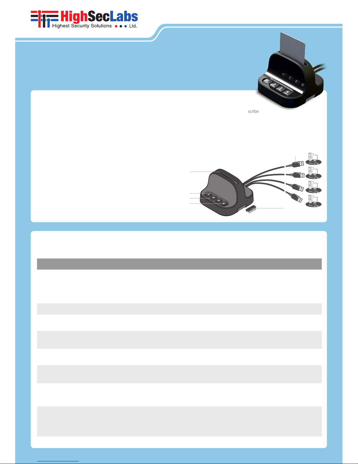
Hardware Terms
The following terms are used to describe
hardware elements in this document:
1. Numbered USB Cables: USB Cables with numbered connectors.
2. Card Reader Slot
3. PC Association Led
4. PC Number Button
5. PC Number Led
6. DIP Switch
1
2
3
4
1
2
3
4
5
6
Initial MDR Configuration Steps
Table 01 describes the initial MDR configuration steps
# Action Action Description Expected Behavior
1
Install Smart Card
Applications
Verify that the applications, drivers and files of the cryptographic
software (CSP) that corresponds to your selected smart card vendor are
installed on all the computers that you plan to connect to the MDR.
Note: Perform a computer restart in case needed to complete the smart
card application installation.
2 Turn PC ON Make sure that all the PCs are turned ON.
3
Test Smart Card using a
Standard Reader
Verify that your smart card setup works correctly on each PC using a
standard smart card reader prior to connecting the MDR.
4 Connect MDR to Power Connect the MDR to Power
1 second beep sound.
All LED lights blink once.
5
Connect USB Cables
to PCs
Connect the MDR USB cables to the computers. Cable numbers
correspond to the numbered MDR buttons.
All PC Number LED lights blink constantly.
6
Insert Smart Card into
the MDR
Insert your smart card into the MDR reader socket.
Note: Make sure the smart card chip is facing towards you.
1 second beep sound.
All lights are OFF.
7
Initial Association with
PC#1
Press PC Number Button#1 to initialize the MDR on PC#1.
PC Number Button#1 light turns ON.
The MDR appears as a smart card reader
under PC#1 device manager.
8
Initial Association with
PC#2
Press PC Number Button#2 to initialize the MDR on PC#2.
Notes: Repeat the process on the remaining PCs.
PC Number Button#1 light turns OFF.
PC Number Button#2 light turns ON.
The MDR appears as a smart card reader
under PC#2 device manager.
©2016 All rights reserve d. HSL logo and produc t names are tradema rks or service t rademarks of Hig hSecLabs Ltd (HSL).
All other mar ks are the proper ty of their respec tive owners. Ima ges for demonstra tion purposes onl y.
HDC10200 Rev. 4.1
Working with the MDR
One completing the initial MDR configuration steps the MDR
is ready for use allowing simultaneous usage of a single smartcard
with multiple PCs.
Smartcard Removal Behavior
Removing the smartcard from the MDR immediately de-associates the MDR
from all coupled PCs. As a result, smartcard-aware applications will notice the
smartcard absence and respond accordingly.
For example, a Windows PC that is configured to require smartcards for
user logon may be set to lock the user’s desktop once the smartcard is
removed.
Re-associating the MDR after Smartcard Removal
In order to continue using the smartcard (after it’s been removed from the
MDR), the user has to insert the smartcard into the MDR and complete steps
6-8 in order to re-associated the MDR with all the corresponding PCs.
De-associating the MDR from a Specific PC
Long pressing a PC Number But ton is the equivalent of removing the
smartcard only from the PC which corresponds to that button without
effecting other associated PCs. To re-associate that PC with the MDR, press
the PC Number Button to initialize the MDR (as described in step 7).
The de-association option is useful in any case a user wants to de-associate
the MDR from a specific PC, without interfering with other PCs which are
associated with the MDR.
For example, when a user has to lock PC#1 by removing the smartcard
yet remain logged-on to PC#2, or when a certain PC is not successfully
associated with the MDR and the user wants to re-associate it.
MDR Operational Modes
Operational Mode settings determines how Active/Passive PC Modes are
set. For example, when the MDR Operational Mode is set to Manual, the
user has to manually press the PC Number Button corresponding to the PC
that requires access to the smartcard.
When the MDR Operational Mode is set to dynamic, auto-association
methods are used to determine which PC will be set as Active.
For example, when the MDR operational mode is set to Activity-Detection
Auto Association, the MDR will automatically actively associate itself to the
computer which requires smart card access based on an activity detection
algorithm.
To preset which MDR Operational Mode is in use (Manual / Auto...etc), there is
a hardware dual in-line package (DIP) switch situated in the underside of the
base. See the switch configuration settings in Table 02, column DIP Switch.
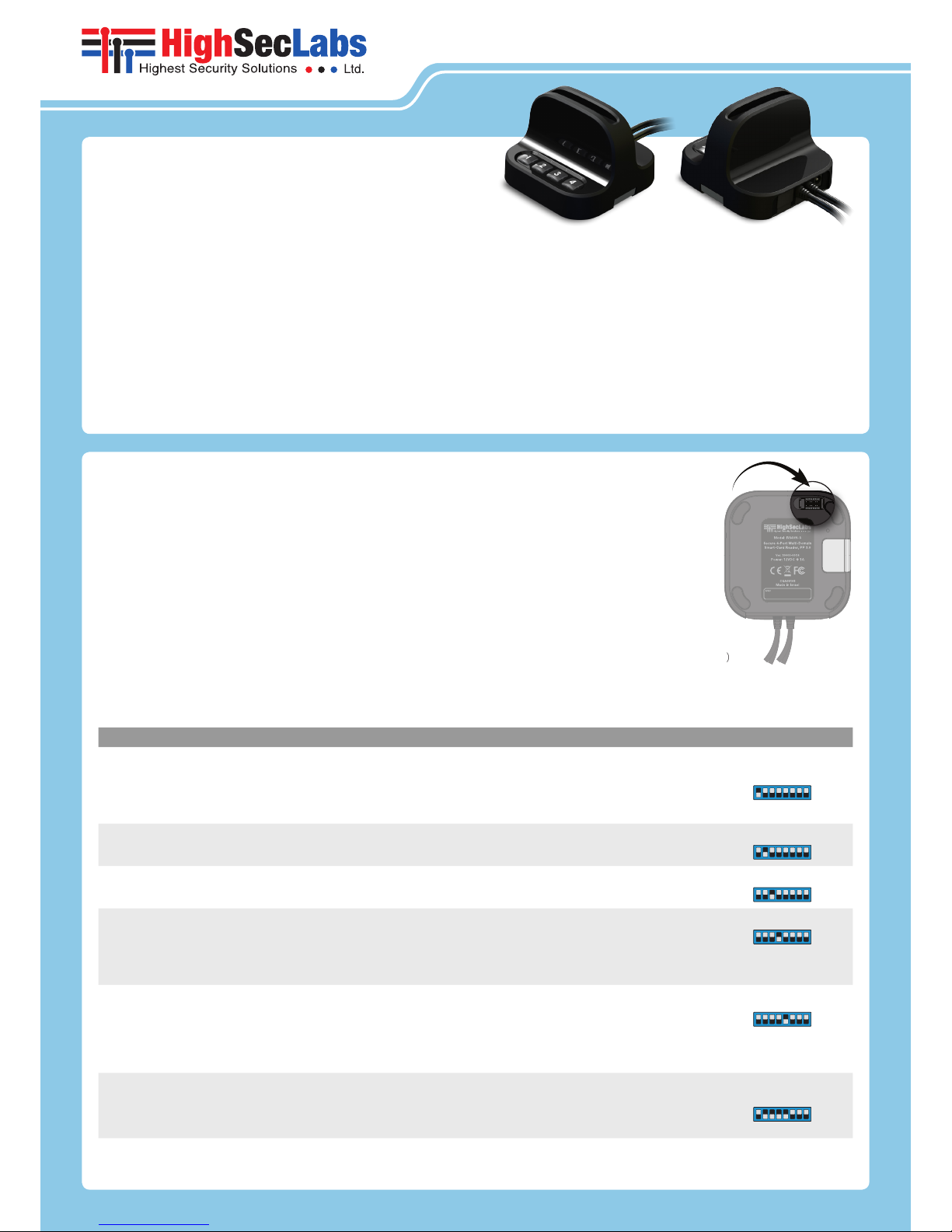
DIP Switch Configuration
1. To change the DIP switch settings, hold the
MDR with the underside facing you. In this
position, the DIP switch should be at the
upper right corner.
2. Gently remove the DIP switch cover.
3. The switch includes 8 slides numbered
from 1 to 8, ordered from lef t to right.
4. When pulled down, slide status is OFF.
When pulled up, slide status is ON.
5. To activate an operation mode, pull down its
corresponding slide.
6. Multiple slides can be turned OFF (pulled down)
at the same time.
7. Refer to Table 02 to adjust DIP switch settings with your work scenario.
Table 02 Operational Modes:
# Mode Description DIP Switch
1 Manual
The user has to ma nually press the PC Number Bu tton corresponding to t he PC that requires access to the sma rt card.
For exampl e: Once the MDR is simultaneo usly connected to two co mputers (PC#1 and PC#2) and a user needs to
authentica te securely via smart ca rd in front of PC#1, by pressing PC Nu mber Button #1 the MDR becom es actively
associated w ith PC#1 and the user c an authenticate successfu lly.
Then when t he user wants to digitally sig n an email on PC#2, pressing PC Number B utton #2 will actively as sociate the
MDR to PC#2 making th e smart card available to th e email application on tha t computer.
1
2
Activit y-Detection Au to
Association
MDR will automa tically associate itse lf to the computer which requir es smart card access base d on its activity detecti on algorithm. Once an app lication attempts to inter act with the smart c ard the MDR automatically associates
itself to the computer that h osts it.
2
3
Power-Detec tion Auto
Association
MDR will automa tically associate itse lf to the computer which requir es smart card access base d on its powerdetecti on algorithm. Once the M DR detects an increase in p ower it automatically ass ociates itself to the compu ter
that initiated i t.
3
4 Device Manager Mode
Determine s whether the MDR remains map ped to the computer’s devi ce manager, or not, upon smar t card removal.
Once enable d, the MDR remains mapped to t he computer’s device manag er upon smartcard remov al, just as a
standard smart card reader would.
When not in use, t he MDR is disconnected f rom the computer’s device man ager upon smart card re moval. This
equals to disconn ecting the USB cables b etween the MDR and the a ssociated PCs but might ca use computability
issues with so me smart card applicat ions.
4
This option is o nly applicable
when used in co njunction with
other mode s, for example 2+4.
5
Auto-Asso ciation Safe
Mode
Applicati on errors and usabilit y issues may occur due to the smar t card being switched to an other computer in the
middle of a smar t card operation ru nning on the active compu ter.
When enabl ed, automatic switching of the smart c ard between computer s will only occur when the sma rt card is idle
(not in use). Auto-Ass ociation Safe Mode prev ents the Auto-Associa tion algorithm from sw itching the smart card in
case it is busy – h ence being used.
When disab led, upon the detect ion of a smart card reque st the MDR immediately sw itches the smart card to th e
requesti ng computer, regardless of whet her the smart card is in use by t he currently active comp uter or not.
5
This option is o nly applicable
when used in co njunction with
other mode s, for example 2+4+5
6
Activit y & Power Auto
Associati on with Device
Manager Mo de and Safe
Mode
(This is th e default mode)
MDR will automa tically associate itse lf to the computer which requir es smart card access base d on either activit y or
power detec tion (depending on the s mart card type). Automati c switching of the smart c ard between computer s will
only occur wh en the smart card is idle (not in us e).
Upon smar t card removal the MDR remains m apped to the computer’s de vice manager, just as a standard sm art card
reader would.
2 + 3 + 4 + 5
RS20N-3 (MDR102) • RS40N-3 (MDR104) | QUICK CONFIGURATION GUIDE
Power Requirements: External, wall-mounted power supply 12VDC, 5W maximum
 Loading...