

Page 1
Secure Combiner KVM Switch User Manual
User Manual: Combiner KVM Switches (K404F, K424F)
User Manual
Models covered in this user manual:
K404F: Secure 4-port DVI Combiner KVM Switch w/audio & DPP
K424F: Secure 4-port Dual-Head DVI Combiner KVM Switch w/audio & DPP
Rev: 2.4
1
Page 2

Secure Combiner KVM Switch User Manual
Rev
Date
Description of changes
1.0
Nov 11, 2010
Initial release
1.1
Nov 20, 2011
Internal review for CC evaluation
2.1
Dec 30, 2011
Released for customers
2.2
Feb 4, 2012
Added security procedures text
2.3
April 19, 2012
Added support for composite
device
2.4
April 3 2015
Updates
Table of Content
Introduction ....................................................................................... 3
Package Contents ............................................................................... 3
Security Features ............................................................................... 4
Main Features .................................................................................... 6
Equipment Requirements .................................................................. 7
Safety Precautions ............................................................................. 8
Front Panel Features .......................................................................... 9
Rear Panel Features ......................................................................... 10
Tamper Evident Labels ..................................................................... 11
Active Anti-Tampering System ......................................................... 11
Product Specifications...................................................................... 12
Before Installation ............................................................................ 14
Installation ....................................................................................... 16
Administrator Setup ......................................................................... 19
Record of Revisions
Operation ......................................................................................... 21
DPP Operation.................................................................................. 23
Single Display Viewing Options ........................................................ 27
Dual Display Viewing Options .......................................................... 29
Summary of Actions ......................................................................... 30
Troubleshooting Guide .................................................................... 32
Copyright and Legal Notice .............................................................. 35
2
Page 3
Secure Combiner KVM Switch User Manual
Important Security Note:
If you are aware of potential security vulnerability while
installing or operating this product, we encourage you to
contact us immediately in one of the following ways:
Web form: http://www.highseclabs.com/support/case/
Email: security@highseclabs.com
Tel: +972-4-9591191 or +972-4-9591192
Important: This product is equipped with always-on active anti-
tampering system. Any attempt to open the product enclosure
will activate the anti-tamper triggers and render the unit
inoperable and warranty void.
Important Security Note:
If you are aware of potential security vulnerability while
installing or operating this product, we encourage you to
contact us immediately in one of the following ways:
Web form: http://www.highseclabs.com/support/case/
Email: security@highseclabs.com
Tel: +972-4-9591191 or +972-4-9591192
Important: This product is equipped with always-on active antitampering system. Any attempt to open the product enclosure
will activate the anti-tamper triggers and render the unit
inoperable and warranty void.
Introduction
Thank you for purchasing this HSL Secure Combiner KVM Switch.
There are many cases where one user needs to work simultaneously
with several computers. The Secure KVM Combiner is designed to
provide users with native windowing environment across isolated
networks.
The HSL Secure KVM Combiner switch uses advanced video
processing technology to draw a high resolution dynamic “mosaic” of
images generated by different computer sources. Built-in video
sources isolation forces unidirectional flow of data through the USB
and video ports. The product was designed and certified according to
NIAP standards.
This User Manual provides all the details you’ll need to install and
operate your new Switch, in addition to troubleshooting guidance—
in the unlikely event of a problem.
Package Contents
Inside product packaging you will find the following:
HSL Secure KVM Product
DC Power Supply
5-button Mouse
User Guidance Documentation
3
Page 4

Secure Combiner KVM Switch User Manual
Security Features
EDID Emulation and Firewall
HSL Secure KVM Switch is the most advanced and secure
commercially available KVM Switch available today. This product is a
derivative of high security KVM product used in newest NATO nuclear
submarines. Below is a summary of some of the security features
incorporated into the product.
Unidirectional Data Paths
Optical diodes used to enforce unidirectional data flow from the
peripheral devices to computers preventing potential leakage paths
between computers even in the severe threat of two infected
computers attacking the KVM.
No Shared Resources
This KVM Switch designed to securely operate even when peripheral
devices are vulnerable to signaling attacks. This KVM Switch does not
allow computer access to any shared resource and does not share
controllable power sources.
Dedicated Processors for Emulation
The Switch features a dedicated processor per computer port to
emulate peripheral devices. This keeps each computer running on
different security levels physically separated and secure at all times,
and prevents any unintended data leakage between computers.
Non-Reprogrammable Firmware
The Switch features custom firmware that is not reprogrammable,
preventing the ability to remotely attack the KVM control logic.
HSL Secure KVM Switch blocks the computer access to the shared
display by using isolated EDID emulators. This arrangement together
with the internal EDID firewall protects from KVM attacks targeting
the external memory effect of the shared display.
USB Ports Protection
Console USB ports are protected from the use of storage and other
unsafe USB devices through strong filtering (independent of
computer protection means). Unqualified devices are rejected when
connected to the Switch. Only mouse and keyboard data are passed
through.
Heavy-duty Steel Enclosure
HSL Secure KVM Switches uses thick steel components to protect the
product from physical tampering and to minimize radiated
electromagnetic emissions that can be snooped or intercepted.
Active Always-On Anti-Tamper
Active chassis anti-tamper system prevents the KVM electronic
circuitry from being accessed and tampered with by permanently
disabling the product once tampering is detected.
Holographic Tamper-Evident Labels
Four serially numbered holographic security tamper-evident labels
are placed on the enclosure surface to provide a visual indication if
the Switch has been opened or compromised.
4
Page 5
Secure Combiner KVM Switch User Manual
High Inter-Channel Analog Isolation
HSL Secure KVM Switches offers exceptionally high isolation between
computer channels to prevent analog leakages across the KVM.
Dedicated Peripheral Port
HSL patented Dedicated Peripheral Ports enables secure use of CAC
or smart-card readers leveraging security.
Common Criteria Listing
The Switch is listed by the Common Criteria organization.
5
Page 6

Secure Combiner KVM Switch User Manual
Main Features
The HSL Secure KVM Switch was designed with the user in mind for
today’s IT environment. Below is a summary of some of the features
incorporated into the Product.
Video Support
DVI models support DVI-I displays as well as VGA and HDMI
via compatible cables.
Dual Display and Resolutions Supported
Products supports dual display and video resolutions of up to HD
(1920 X 1200 pixels).
Real-time and real quality video
Pixel-by-pixel video image. No quality loss, latency, reduced colors,
dropped frames or artifacts. Fastest digital video processing
technology available in any KVM today. Less than 30 millisecond
latency.
Easy customization
Advanced Scaling Function
The HSL Secure KVM Combiner has an advanced scaling function
allowing the user to scale the video source 2x and 4x smaller to assure
good view and superb work experience. User can now fit 4 full HD
sources on a single HD screen by scaling each source and all in real
time with no data loss.
Scale and Tile Modes
Allowing users to focus on a main source while viewing the other
sources or tile all of the sources equally
DPP port
Dedicated peripheral port enables to connect CAC and smart card
readers to product. Product is designed with complete isolation
between DPP data, such as user authentication smart card reader
data, and all other product traffic.
Administrator mode enables easy customization of channels, colors,
cursors, task-bar, background etc. User programmable buttons
enable quick setting of user defined screen arrangements.
Audio Support
The HSL Secure KVM Combiner supports audio out switching.
Microphone switching is not supported to prevent analog leakages
through audio ports.
6
Page 7

Secure Combiner KVM Switch User Manual
Equipment Requirements
Cables
It is highly recommended to use HSL Cable Kits for product to ensure
optimal security and performance.
One Cable Kit is required per connected computer.
Operating Systems
Product is compatible with devices running on the following
operating systems:
• Microsoft® Windows®
• Red Hat®, Ubuntu® and other Linux® platforms
• Mac OS® X v10.3 and higher.
USB Keyboard console port
The product console USB keyboard port is compatible with Standard
USB keyboards.
Notes:
a. For security reasons products do not support wireless
keyboards. In any case do not connect wireless keyboard to
product.
b. Non-standard keyboards, such as keyboards with integrated
USB hubs and other USB-integrated devices, may not be fully
supported due to security policy. If they are supported, only
classical keyboard (HID) operation will be functional. It is
recommended to use standard USB keyboards.
USB Mouse console port
The product console USB mouse port is compatible with standard
USB mice.
Notes:
a. Console USB keyboard and mouse ports are switchable, i.e.
you can connect keyboard to mouse port and vice versa.
However, for optimal operation it is recommended to
connect USB keyboard to console USB keyboard port and
USB mouse to console USB mouse port.
b. Console USB mouse port supports Standard KVM Extender
composite device having a keyboard/mouse functions.
c. For security reasons products do not support wireless mice.
In any case do not connect wireless mouse to product.
PS/2 Mouse and Keyboard console ports
The product console PS/2 keyboard and mouse ports are compatible
with standard PS/2 keyboards and mice.
Video Support
Combiners supports DVI-I displays as well as VGA and HDMI
via compatible cables.
Resolutions Supported
DVI Dual-link supports resolution up to 2560 x 1600.
DVI Single-link supports resolution up to 1920x1200.
User Audio Devices
Product is compatible with the following types of user audio
devices:
Stereo headphones;
Amplified stereo speakers.
Note: In any case do not connect a microphone to product audio
output port including headsets.
DPP Port
The product operates with authorized USB devices plugged into the
console DPP Port, such as USB smart-card reader or Common Access
Card (CAC) reader.
7
Page 8

Secure Combiner KVM Switch User Manual
Safety Precautions
Please read the following safety precautions carefully before using
the product:
Before cleaning, disconnect the product from DC
power.
Be sure not to expose the product to excessive
humidity.
Be sure to install the product on a clean secure
surface.
Do not place the DC power cord in a path of foot
traffic.
If the product is not used for a long period of time,
remove the product’s wall-mount power supply from
the mains jack.
If one of the following situations occurs, get the
product checked by a qualified service technician:
The product’s power supply is overheated,
damaged, broken, causes smoke or shortens
the mains power socket.
The product has obvious signs of breakage or
loose internal parts.
The product should be stored and used only in
temperature and humidity controlled environments
as defined in the product’s environmental
specifications.
The wall-mount power supply used with this product
should be the model supplied by the manufacturer
or an approved equivalent provided by HSL or an
authorized service provider. The use of improper
power source will void product warranty.
Liquid penetrates the product’s case.
The product is exposed to excessive moisture
or water.
The product is not working well even after
carefully following the instructions in this
user’s manual.
The product has been dropped or is physically
damaged.
8
Page 9
Secure Combiner KVM Switch User Manual
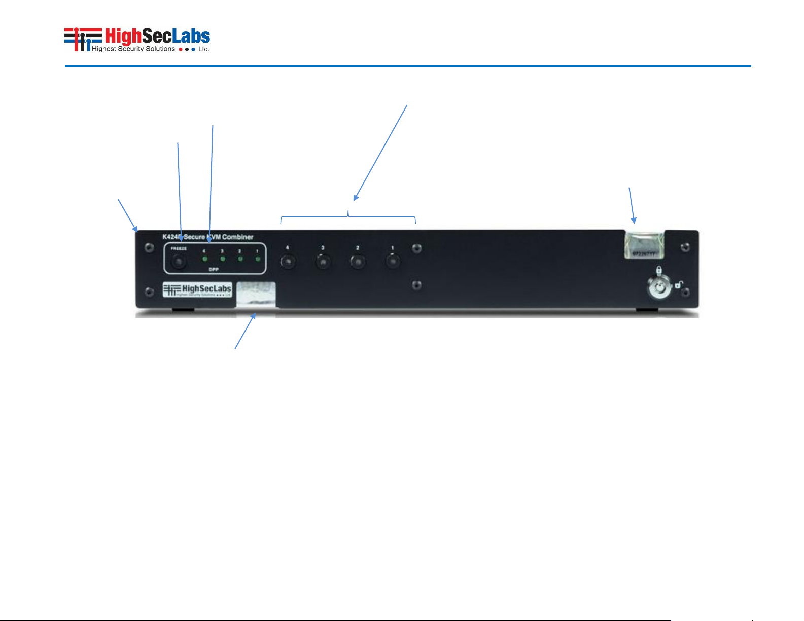
1 – Steel enclosure
2 – DPP (Dedicated Peripheral Port) Status LED ("Freeze")
3 – DPP channel select LEDs
4 – Channel Select push-buttons and LEDs
5a-5b – Holographic Tamper Evident Labels
1 2 3
5b 4 5a
Front Panel Features
9
Page 10
Secure Combiner KVM Switch User Manual
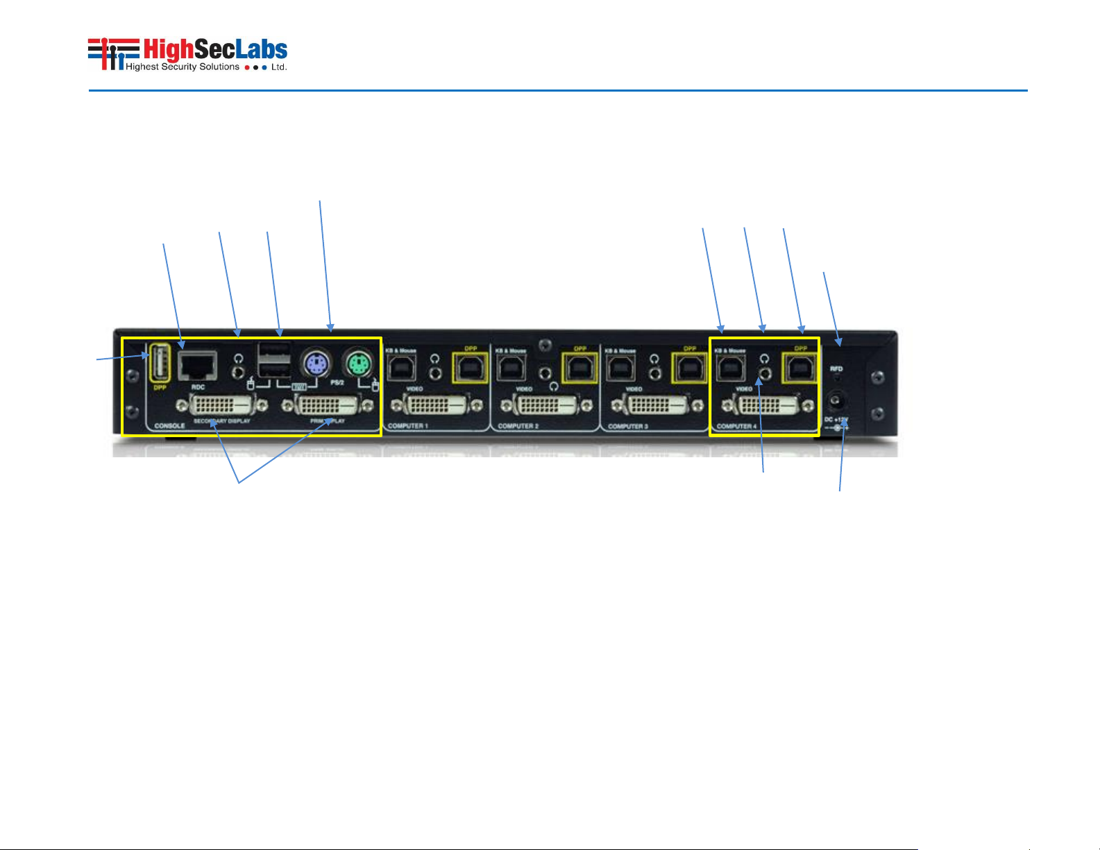
Console Area
1 - DPP (Dedicated Peripheral Port) console USB jack
2 - RDC remote control port RJ-45 (for future use)
3 – Audio console output 3.5 mm stereo jack
4 - USB Keyboard & Mouse jacks
5 – PS/2 Keyboard & Mouse jacks (Mini-DIN)
6 – Console 2 X DVI-D video input jacks & diagnostic LEDs
2 4 5
6
Computer Area
7 - Computer USB Keyboard & Mouse jack
8 - Computer audio input jack 3.5mm stereo
9 - Computer DPP USB jack
10 - Computer DVI-D video input jack
General
11 - DC Power input jack – barrel type
12 – Restore Factory Default
10
11
3 1 8
7 9 12
Rear Panel Features
Model shown K424F
10
Page 11
Secure Combiner KVM Switch User Manual
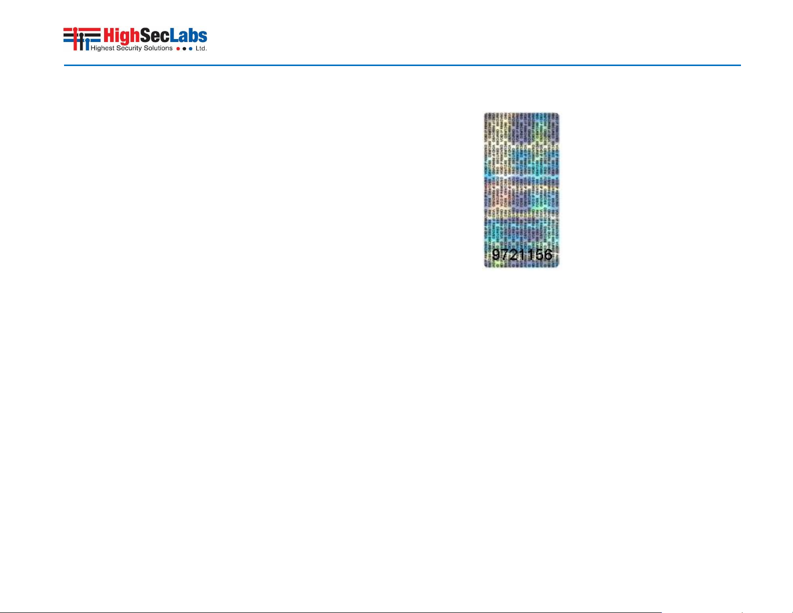
Tamper Evident Labels
HSL Secure KVM Switch uses 4 holographic tamper evident labels to
provide visual indications in case of enclosure intrusion attempt.
These labels indicate white dots or the text “VOID” once removed.
When opening product packaging inspect the 4 tampering evident
labels.
If for any reason one or more tamper-evident label is missing,
appears disrupted, or looks different than the example shown here,
please call HSL Technical Support and avoid using that product.
HSL Holographic Tampering Evident Label
Active Anti-Tampering System
11
HSL Secure KVM Switch is equipped with always-on active antitampering system. If mechanical intrusion is detected by this
system, the Switch will be permanently disabled and LED will blink
continuously.
If product indication tampered state (all LEDs blinking) - please call
HSL Technical Support and avoid using that product.
Page 12

Secure Combiner KVM Switch User Manual
Product Specifications
Enclosure Heavy-duty extruded aluminum
enclosure with metal faceplate
Power Requirements 12V DC, 5A (maximum) power adapter
with center-pin-positive polarity
AC Input 100 to 240VAC
No. of Secure Channels 4
No. of Computers Supported 4
Displays Supported
K404F: 1 x single-link DVI-D display;
HDMI interface supported with
adapter
K424F:
2 x single-link DVI-D display; HDMI
interface supported with adapter
Output Display Resolutions Supported Up to 1920x1200 pixels
Input video resolution Up to 1920x1200
Input Windows Size 800 x 600 (4:3) SVGA; or
1280 x 1024 (5:4) SXGA; or
1920 x 1080 (16:9) HD1080;
or
1920 x 1200 (16:10) WUXGA.
Console Keyboard Input USB Type-A female connector or PS/2
Mini-DIN 6 pin female connector
Console Mouse Input USB Type-A female connector or PS/2
Mini-DIN 6 pin female connector
Console DPP Input USB Type A
Console Display Port 1 DVI-D female connector (K404F)
2 DVI-D female connector (K424F)
Console Audio out 3.5mm stereo jack
PC Keyboard/Mouse Ports USB Type-B jack
PC CAC Ports USB Type-B jack
PC Audio Input 3.5mm stereo jack
PC Video Input Port DVI-D Single-link female
Port Selectors push-buttons 4
LED Indicators 4
User Functions
Toggling between normal mode and
system modes by mouse side buttons
click (5-Buttons mouse).
Windows can be moved and resized.
Cascading button arranges all 4
windows one on top of the other.
Tile button arranges all 4 windows in a
mosaic.
Help button presents on-screen basic
usage guidance.
Vertical and horizontal scroll bars to
enable user control of viewable
window.
Minimize window to task-bar.
12
Page 13

Secure Combiner KVM Switch User Manual
Colored Task-bar and window border
indicating channel.
Mouse wheel cyclic toggling between
active windows in system mode.
Double click to maximize a window to
a full screen.
Legacy mode – toggling between
windows by keyboard Control +
Function keys [Optional].
3 User defined preset buttons to save
or load user settings.
Disable channel function.
Administrator mode
Selectable system cursor pointers.
Selectable window border widths.
Selectable window border colors.
Selectable task-bar sizes.
Selectable video output resolutions
[model specific – see table above].
Operating Temp 32° to 104° F (0° to 40° C)
Storage Temp -4° to 140° F (-20° to 60° C)
Humidity 0-80% RH, non-condensing
Security Accreditation NIAP Common Criteria
Product design life-cycle 10 years per
13
Page 14

Secure Combiner KVM Switch User Manual
Before Installation
Unpacking the Product
Before opening the product packaging, inspect the packaging
condition to assure that product was not damaged during delivery.
When opening the package, inspect that the product Tamper Evident
Labels are intact.
Where to locate the Product?
The enclosure of the product is designed for desktop or under the
table configurations. An optional Mount Kit is available.
Product must be located in a secure and well protected environment
to prevent potential attacker access.
Consider the following when deciding where to place product:
Product front panel must be visible to the user at all times.
The location of the computers in relation to the product and
the length of available cables (typically 1.8 m)
Warning: Avoid placing cables near fluorescent lights, airconditioning equipment, RF equipment or machines that create
electrical noise (e.g., vacuum cleaners).
Display selection considerations
Proper selection of user display is critical for the success of any
Combiner KVM deployment. The information provided here
represents the information gained during evaluation and deployment
projects.
• Avoid using old CRT displays.
• Some projects invested significant resources in the overall project
design and implementation but neglected the display and
peripherals. Users may reject the new system if proper display not
used with the system. As large LCD cost going down daily, it become
easier and cheaper to retrofit the user desktop completely during
these projects.
• Proper size of the display is critical. To enable simultaneous work
with several windows LCD panels larger than 22” diagonal are
recommended.
• Try to use the larger LCD size possible (taking the user workstation
/ table size into consideration).
• Check if the display adjusts automatically to resolution changes.
This feature is essential to support window maximization.
• Native resolution of the display should match output resolutions
supported by the Secure Combiner KVM.
• Display should support DVI input. HDMI can be used with proper
DVI to HDMI cable or adapter. In this case check audio out channels
cannot be routed through HDMI.
• It is recommended to involve the users in the display selection
process during evaluation and initial deployments.
• Consult support with specific display models and technical
specifications.
• DVI-I to VGA converters cannot be used with the Secure Combiner
KVM as it does not support analog video.
• Note that when using a Dual-link DVI display with the 104X product
the KVM to display cable and KVM cables must be Dual-link as well.
14
Page 15

Secure Combiner KVM Switch User Manual
Dual Display Model K424F
• K424F uses two displays. It is preferable that both displays will be
the same type and model.
• Displays must be landscape oriented and installed side by side in
close proximity to one another. Primary on the left and secondary on
the right side.
• Displays must be either 1920 x 1080 or 1920 x 1200 native
resolution.
15
Page 16

Secure Combiner KVM Switch User Manual
Installation
Connecting devices to product console
Product requires connection of all devices and computers prior to
powering it up.
Note: some devices such as user display would not be recognized if
connected after product is already powered up.
See figures above for connector locations.
Connect user display/s. Mark which display is coupled with which
computer. It is also recommended to mark which computer is
coupled with which channel.
Connect user keyboard and mouse to console keyboard and
mouse ports.
Connect headphones/speakers to console audio out port
(optional).
If the computer uses a smart card reader/USB device, connect
the smart card reader/USB device to the console DPP port
(optional, model pending).
Notes:
1. Console USB mouse and keyboard ports are switchable, i.e. you
can connect keyboard to mouse port. However, for optimal
operation it is recommended to connect USB keyboard to
console USB keyboard port and USB mouse to console USB
mouse port.
2. For security reasons products do not support wireless keyboards.
In any case do not connect wireless keyboard to product.
3. Non-standard keyboards, such as keyboards with integrated USB
hubs and other USB-integrated devices, may not be fully
supported due to security policy. If they are supported, only
classical keyboard (HID) operation will be functional. It is
recommended to use standard USB keyboards.
4. Console USB mouse port supports Standard KVM Extender
composite device having a keyboard/mouse functions.
2. Connecting the Computers
Using USB cables, connect each computer to the USB type B port
in "computer interface ports" area on product.
If computer uses audio output, e.g. speakers/headphones,
connect audio cable from its audio output port to the
corresponding audio input port on product.
If the computer uses a smart card reader/USB device, connect a
USB cable between the DPP-enabled computer and the
corresponding DPP port on product.
Note:
1. If the number of product channels is larger than the number
of sources used, make sure the computers are connected in
a row starting from computer #1. For example, if there are 3
channels used, connect computers to channels #1, #2 and
then #3.
2. The USB cable must be connected directly to a free USB port
on the computer, with no USB hubs or other devices in
between.
3. Power up
Connect DC power supply.
Power up user display/s. Select through display setup menu the
appropriate video input if applicable.
Power up the connected computers.
Power up the product.
16
Page 17

Secure Combiner KVM Switch User Manual
When you power up your computers, the product emulates display,
mouse and keyboard on each port and allows your computers to boot
normally. You should be able to move the mouse cursor on the
primary display connected to computer #1.
Check to see that the keyboard and mouse are working properly on
each computer.
Repeat this check with all occupied ports to verify that all computers
are connected and responding correctly.
If you encounter an error, check your cable connections for that
computer and reboot. If the problem persists, please refer to the
Troubleshooting section in this User Manual.
DPP Installation
In case computer and product support DPP functionality, such as
user authentication smart card reader, do the following:
1. Connect USB device, such as smart card reader, to DPP port
on product console
2. Connect DPP input port on product to any free USB port on
computer using a USB cable.
Note: Do not connect the USB cable if DPP functionality is
not needed for that computer.
If the USB device is detected but not authorized, as not being a
Smart Card or CAC reader, it will be rejected for security reasons.
This will be indicated by DPP status LED illuminating steady red.
Note: If during installation as a result of bad output resolution
(resolution not supported by display) the video image on the user
display is lost it is possible to recover the device through the use of
Restore Factory Defaults switch (see item 17 in page 12). Pressing
this switch momentarily will return the Secure Combiner KVM to
the original production settings including lowest output resolution.
For information on how to reset the device to factory defaults see
the Troubleshooting section of this manual.
If only some of the computers use DPP functionality, such as user
authentication, make sure that computer #1 is connected to the USB
device. If needed, switch channels/computer mapping to create this
configuration.
When product is powered ON and connected USB device is qualified
and ready for use, the DPP status LED ("Freeze") will illuminate steady
green.
17
Page 18

Secure Combiner KVM Switch User Manual
Typical system diagram
18
Page 19

Secure Combiner KVM Switch User Manual
Administrator Setup
Now that the Secure Combiner KVM is connected and powered-on
it is a good opportunity to setup some operational settings.
To enter administrator setup mode the administrator key should be
inserted into the front panel keylock and rotated in clockwise
direction. Once in administrator clicks on setup icon at the bottom
left side of the screen, the Main Admin Setup windows appears and
can be accessed. Details about administrator setup windows:
Main Admin Menu – Enables selection of System setup
window or channel specific window using mouse.
Channel menu – Enables selection of channel input
resolution (4 options) and border color from 16 color
options.
System menu – Enable system level settings. Administrator
can select:
- Display output resolution from 2/6/8 options;
- Border width from 6 options;
- Taskbar size from 2 options; and
- System cursor type from 4 options.
Note: Rotation of the key lock to Administrator setup mode also
affect: the following:
1. User preset buttons will become inactive.
2. All three user presets will be erased.
This is normal system behavior that designed to avoid configuration
conflicts.
Note about input resolution setting: Selection of input resolution
that does not match the attached PC will result unreadable image at
that window. This may be fixed by entering administrator mode and
change input resolution setting or by changing host resolution.
Notes about display resolution setting:
- The Secure Combiner KVM channel resolution, selected from the
channel menu, determines the size of the channel window. It will not
affect the actual resolution projected by the connected PC.
- The Secure Combiner KVM is capable of scaling the image in two
possible factors: 2x and 4x allowing the user to fit more information
on the same display size.
- Selection of resolution higher or lower than resolution range of
connected display may result image loss! In this case you can change
display to different type or restore factory defaults.
- To restore factory default settings – use a paper clip or another
sharp object and press momentarily the recessed RFD switch located
at the rear side above the DC power jack.
- See table in page 14 for supported output resolutions per model.
Once completed to set the required settings, the administrator key
should be rotated back to the locked position and key must be
removed to enable normal product operation.
After Installation Checklist
Once completed to set requires settings – check the final device
product configuration with all connected computers operating:
1. Check that each window is connected to the proper PC and have
the required border color.
2. Check that each window is coupled to the proper keyboard and
mouse (no cables are crossed between channels).
3. Check that each window is coupled to the proper DPP input.
19
Page 20

Secure Combiner KVM Switch User Manual
4. Check that each window is coupled to the proper audio output (if
applicable).
5. Check that all video cable thumb screws are secured.
6. Check that administrator key was removed from the device.
Dual Display Channel #1 Input resolution setting window
Installation is similar to a single display with the following changes:
1. Displays must be either 1920 x 1080 or 1920 x 1200 native
resolution. Do not use higher resolution as the image will be shown
as a smaller window or will be rescaled (resulting a degradation in the
displayed video quality.
2. It is recommended that both displays will be identical type and
model.
3. Displays should be oriented in landscape.
4. Left side display must be connected to the primary console display
output jack (the right side jack when looking from the rear).
5. Conversion to VGA monitor is not recommended.
20
Page 21

Secure Combiner KVM Switch User Manual
Operation
Now that you have connected your console and computers to the
Switch, it is ready for use. Default channel after power up is channel
#1 as indicated by channel select LED #1 illumination. You can select
which computer you wish to control by one of the following methods:
Default Channel
After product boots up, the default active channel will be channel
#1. This will be indicated by white color illumination of
push-button #1.
Product Mapping to Sources
Product mapping to sources is indicated by stickers/labels specifying
which channel is mapped to which computer.
Front Panel Push-Buttons
Following power up, the default channel is #1.
The user can select any other channel by pressing the appropriate
front panel push button.
The mouse cursor will be positioned at the center of the selected
computer display.
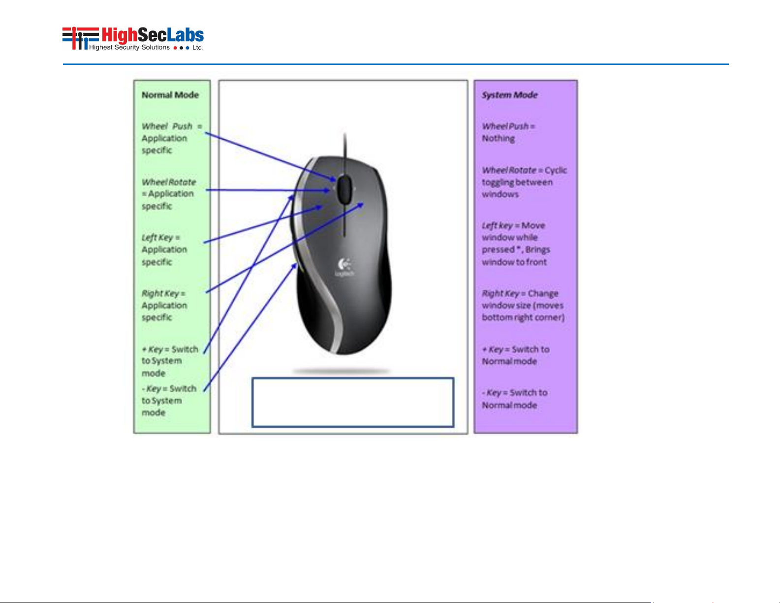
Device control is done using the 5-buttons mouse and display
interaction. The use of 5-buttons mouse enables the user to fully use
all standard wheel mouse buttons for application specific tasks and
still operate Secure Combiner KVM specific functions using the 2
extra side buttons.
The user may easily toggle between normal and system mode by
pressing one of the +/- side buttons.
21
Page 22
Secure Combiner KVM Switch User Manual
22
Page 23

Secure Combiner KVM Switch User Manual
DPP Operation
The product is equipped with DPP port enabling connectivity to
external USB-devices such as smartcard reader.
Summary of rules that apply to DPP switching:
It is assumed that a "connected channel" is when:
1. Product is powered ON
2. The USB device connected to product console is qualified
and ready for use, as indicated by the DPP status LED
illuminating steady green.
3. The channel DPP port on product is connected via USB cable
to a USB port on computer.
When the USB device connected to the DPP console port is
qualified, the DPP status LED on the front panel would
illuminate steady green.
o When connecting a USB device that is rejected for
security reasons to the product's DPP port, the DPP
LED will illuminate steady red and USB device will be
inoperable. In such case the USB device must be
replaced with a qualified device, either USB smart
card or CAC reader.
Since channel #1 is the default active channel after power up
and in case only some of the channels operate with a USB
device, it is recommended to make sure computer #1 is
connected to USB device.
Once the user switches channels, for example to channel #3,
DPP functionality will move to computer #3 and be indicated
by channel #3 DPP LED turning steady green.
In case user switches to a channel that is not connected to a
USB device, the DPP function will remain with the last
channel that had DPP connection.
Normal Mode
The Secure Combiner KVM enables simultaneous interaction with 24 different computers using a single or dual display, keyboard and
mouse. When the user interacts with an application at a specific
window - that channel is active and the mouse and keyboard
affecting only that channel. The top left corner of the active channel
window is white as an indication. In Normal mode there is always one
channel which is considered to be active. Mouse, keyboard and audio
are mapped to the active channel.
The user may move to a different channel by:
1. Switching first to system mode. While in system mode the cursor
will change to the selected system mode cursor and will enable free
movement throughout the display area. Once in system mode the
user may point at another window and use the +/- to make it active.
2. Using front panel push-buttons to select a different channel.
When the Secure Combiner KVM is in Normal Mode:
• Mouse cursor of the active computer (channel) is controlled by the
console mouse.
• Mouse cursor symbol is generated / controlled by the computer
operating system / application.
• Mouse movement is limited to the active window area.
• All mouse buttons (and wheel) will function based on the computer
assigned specific role (not affected by the KVM) (the mouse side
buttons are used to exist normal mode and switch to system mode).
• Keyboard is mapped to the active window computer.
• Audio output will only be heard from active computer.
• Active window will always be on top of all other windows.
• Task bar not shown on user display, buttons are not accessible.
23
Page 24

Secure Combiner KVM Switch User Manual
• Pressing + / - (on the side of the mouse) mouse buttons will toggle
the Secure KVM to System Mode.
• When using a PS/2 (which does not have the side buttons) pressing
both right and left buttons at the same time will also toggle the KVM
to System Mode.
System Mode
The mouse +/- side buttons triggers cyclic toggling between modes.
System mode can be easily identified by the appearance of the title
bar / task bar at the bottom of the display.
The Secure Combiner KVM system mode enables the user to manage
his/her combined desktop and customize it for the job being done.
This mode also enables the user to move between windows and to
minimize/ maximize windows as needed.
In system mode there is also an active channel, indicated by a white
top left corner but the mouse is controlled by the Secure Combiner
KVM and not mapped to the active channel.
When the Secure Combiner KVM is in System Mode:
• Mouse cursor is controlled by the system mouse.
• Mouse cursor is generated / controlled by the Combiner KVM.
• Mouse movement is unlimited in all display area.
• Keyboard is routed to the active window (active window is always
in front).
• Audio output is switched from the active window PC.
• Task bar visible and buttons are accessible.
• Pressing + / - mouse buttons will change to Normal Mode and the
active window will be the window where the system cursor was last
positioned.
• Left clicking on a window will bring it to the front and make it the
active window.
• Pressing left mouse button and holding – will drag the window
under it.
• Double clicking on a window will maximize that window to full
screen.
• Right click on the bottom right corner of a window and dragging will
allow changing the window size (limited by the size set under the
channel menu).
• Pressing both right and left keys on an active window will allow
moving the picture inside the window (only applicable of the source
resolution is larger the window size).
• Pressing and holding the +/- side mouse buttons and moving the
mouse wheel will rescale the window (change the size of the input
picture). This will be further explained in the scaling part of this
manual.
Change of Active Window
When in system mode there is always one window which is
considered as the active window. The active window top left corner
will be marked in white (as appose to black in all other windows) and
its icon on the task bar will show as pressed.
Active Window is the window which the keyboard, audio and CAC
device mapped to. In normal mode the mouse will also be mapped
to this window.
Switching between active windows (when in system mode) is simply
done by right clicking on another window with the mouse curser.
Another option is pushing the front panel push buttons.
Another option to switch between active windows in system mode is
by using the wheel in the mouse. Windows will move to the front at
a cyclic sequence.
24
Page 25

Secure Combiner KVM Switch User Manual
Moving Between Windows in Normal Mode
When in normal mode moving between windows can be done either
by switching to system mode (by pressing the mouse side buttons),
pointing at the new window and switching back to normal mode (by
pressing the mouse side buttons again). Another option is to use the
front panel push buttons.
Dragging a Window
In order to move a window user should first switch to system mode
by pressing + or – mouse side buttons. In system mode, hold the left
mouse button when the system cursor located on the desired
window and the window will move. Release left mouse button to
drop window in place.
Notes: Window movement to the left side is limited by the display
boundary.
Window movement to the right side is unlimited (window may be
pushed out of the display viewable area).
Window Resizing
In order to resize a window the user should first switch to system
mode by pressing + or – mouse side buttons. In system mode, the
user should drag the mouse while holding the right mouse button
when the system cursor located on the bottom right corner of the
desired window. Release right mouse button to freeze window size.
Note: Window size is limited by the size set for the window under the
channel menu.
Window Internal Scroll
When window size is smaller than input image size it might be
required to “move” the image inside the window. This is done by
pointing at the window, pressing both mouse buttons at the same
time and moving the mouse. Release the mouse buttons to freeze
the position of the window.
Help button
The “?” button located at the task bar (see figure below) show mouse
functionality bitmap with mouse functions.
Maximizing a window to full screen mode
To maximize a window to its full size – enter System Mode by pressing
+ or – mouse side buttons then bring the system cursor to the
window that should be maximized and then double click on that
window.
The selected window will maximize to its native input resolution. No
other windows or bars will be displayed.
To leave maximize mode – change back to system mode (by pressing
the mouse side buttons) and re arrange windows as needed.
Changing to system mode will
Deactivating / activating channels
The user can remove from the Secure Combiner KVM display inactive
channels. In order to deactivate a channel the user should enter
system mode and then move the system cursor to the desired
channel button at the task bar and double-click on it. Red X should
appear on that channel (see figure below).
In some cases the user may want to deactivate a live channel for
operational reasons. The Secure Combiner KVM will display instead
on that channel a background color.
Repeating this process will cancel this status and reactivate that
channel.
Once a channel had been deactivated it would not participate in
cyclic toggling between windows and will not be displayed in anyway.
25
Page 26

Secure Combiner KVM Switch User Manual
Dual display operation [K424F]
Maximizing a window
When in system mode, double-clicking on a window will maximize
that window to full screen. If the window is shown on both displays
it will maximizes at the display where a larger portion of that window
lying at. For example: if 60% of the window is at the primary display
– it will maximize at the primary. When it is maximizing – the other
40% of that window will disappear from the secondary display. The
second monitor will still display the same windows as before
accessing the full screen mode. Any other windows on the display to
which the window was maximized will be hidden behind the
maximized window.
In dual display mode, the tile function will place channels 1 and 3
windows on the primary display and channels 2 and 4 windows at the
secondary display.
The Secure Combiner KVM includes a scaling function. The scaling
function allows the user to reduce the size the source image without
losing information, enabling him to see more of the sources on
limited screen space. Scaling is done by an advance scaling algorithm.
Tile Feature
The tile feature is accessed from System Mode by clicking on the Tile
button located on the task bar. By pressing tile the windows will
arrange in tile mode but will automatically be scaled by 1:2x factor.
For example, if the input source resolution is 1920 x 1080 the image
displayed in the source window will be 960 x 540. The size of the
window is, as always, determined by the output resolution (will be a
quarter of the available screen area). Tile is actual a preset of system
mode and once in tile mode all system mode functions are available.
Scale a specific Window
From System mode it is possible to scale a specific window simply by
pointing on the active window, pressing the mouse side buttons and
moving the mouse wheel.
This will toggle the scaling of the active window between 1:2x, 1:4x
and no scaling keeping the actual window frame size fixed.
It is also possible to scale a window (both from system and normal
modes by using the CTRL | CTRL | +/- key combination where
pressing + will reduce the scaling (from 1:4X to 1:2X and from 1:2X to
no scaling) and the – will increase the scaling (from no scaling to 1:2X
and from 1:2X to 1:4X).
Scale Feature
By pressing the Scale button on the System Mode task bar the screen
will be re-arranged as follow:
The active window centered (not scaled) and the other windows will
move to the right side and scaled 1:4x.
It is still possible in this mode to use all standard System Mode
functions to switch active between windows.
Also, once in scale mode moving the mouse wheel will toggle
between windows making a different source the central display.
Using the front panel push buttons will change the active window
without repositioning the windows.
26
Page 27

Secure Combiner KVM Switch User Manual
Single Display Viewing Options
27
Page 28

Secure Combiner KVM Switch User Manual
28
Page 29

Secure Combiner KVM Switch User Manual
Dual Display Viewing Options
29
Page 30

Secure Combiner KVM Switch User Manual
Summary of Actions
30
Page 31

Secure Combiner KVM Switch User Manual
31
Page 32

Secure Combiner KVM Switch User Manual
Important Security Note:
If you are aware of potential security vulnerability while
installing or operating this product, we encourage you to
contact us immediately in one of the following ways:
Web form: http://www.highseclabs.com/support/case/
Email: security@highseclabs.com
Tel: +972-4-9591191 or +972-4-9591192
Important: If the unit’s enclosure appears disrupted or if all
channel-select LEDs flash continuously, please remove product
from service immediately and contact HSL Technical Support at
http://www.highseclabs.com/support/case/
Important: This product is equipped with always-on active antitampering system. Any attempt to open the product enclosure
will activate the anti-tamper triggers and render the unit
inoperable and warranty void.
Troubleshooting Guide
General
Problem: No power - No video output, none of the front panel LEDs
are illuminating.
Solutions:
Check AC cable connection to make sure product receives power
properly. Replace cable if needed. If problem persists, contact
your system administrator or our technical support.
Problem: Product enclosure appears disrupted or all channel-
select LEDs flash continuously.
Solution: The product may have been tampered with. Please
remove product from service immediately and contact
Technical Support.
32
Page 33

Secure Combiner KVM Switch User Manual
Keyboard
Problem: Mouse and keyboard are not working (two channels)
Solutions:
Check that computer USB and video cables are not crossed
i.e. computer #1 video is connected to channel #1 while USB
keyboard and mouse cables are connected to channel #2.
Problem: Keyboard does not work (all channels)
Solutions:
Check that the keyboard you are using is properly connected
to product.
Check that the USB cable between the product and computer
is properly connected.
Try connecting keyboard to a different USB port on
computer.
Make sure the keyboard works when directly connected to
computer, i.e. the HID USB driver is installed on computer;
this may require computer reboot.
It is recommended to use standard USB keyboards and not a
keyboard with an integrated USB hub or other USBintegrated devices.
If the computer is coming out of standby mode, allow up to
one minute to regain mouse function.
Try a different keyboard.
Do not use a wireless keyboard.
Mouse
Problem: Mouse cursor does not switch from primary to secondary
display.
Solutions: Driver supporting multiple displays was not installed or
not installed properly on computer. Reinstall driver.
Problem: Mouse and keyboard are not working (two channels)
Solutions:
Check that computer USB and video cables are not crossed
i.e. computer #1 video is connected to channel #1 while USB
keyboard and mouse cables are connected to channel #2.
Problem: Mouse does not work (all channels)
Solutions:
Check that the mouse you are using is properly connected to
product.
Check that USB cable between the product and computer is
properly connected.
Try connecting mouse to a different USB port on computer.
Make sure the mouse works when directly connected to
computer, i.e. the HID USB driver is installed on computer;
this may require computer reboot.
It is recommended to use standard USB mice.
If the computer is coming out of standby mode, allow up to
one minute to regain mouse function.
Try a different mouse.
Do not use a wireless mouse.
Problem: both keyboard and mouse are not working (one channel)
Solution: Use computer Device Manager Utility to see product and
solve problem.
33
Page 34

Secure Combiner KVM Switch User Manual
Video
Problem: No video image in user display (all channels)
Solutions:
Check that displays are properly powered.
Check that video cable is properly secured at both sides.
Check at the displays' on-screen menu that sources selected
match the cables connected to displays.
Check if display video mode is the same as computer's video
mode (e.g. DVI and DVI, etc.).
Check that displays' diagnostic LED is steady green – if not,
change displays, change displays' cables or call technical
support.
Problem: No video image in user display (specific channel)
Solutions:
Reboot product first, then disconnect and reconnect the
video cable and reboot the computer.
Check that the video cable connecting computer and product
is properly secured at both sides.
Check that computer video output is sent to the connected
video connector (if computer supports multiple displays).
Check that computer resolution matches connected display
capabilities.
Connect the display/s directly to the computer to confirm
that video output is available and that a good image is shown.
Problem: Bad video image quality (some or all channels)
Solutions:
Check that all video cables are properly connected to
product, computer, and display.
Check that cables are original cables supplied by HSL.
With everything connected, power-cycle the product to reset
the video. Make sure the Video Diagnostic LED is solid green.
Check that the displays that you are using support the
resolution and refresh-rate setting on computer.
Lower the video resolution of your computer.
Connect displays directly to computer showing bad video
image to see if problem persists.
DPP
Problem: DPP is not working (two channels)
Solutions:
Check that computer USB and video cables are not crossed
i.e. computer #1 video is connected to channel #1 while USB
device is connected to channel #2.
Problem: DPP is not working (all channels)
Solutions:
Check that the USB device is properly connected to product
console.
Check that the DPP status LED is steady green. If DPP status LED
is illuminated steady red the device is rejected or non-qualified
for security reasons. To resolve please connect a USB smart card
or CAC reader or contact your system administrator.
Problem: DPP is not working (one channel only)
Solutions:
Check that device is working properly when connected
directly to computer.
Check that there is a USB cable connected between the
computer and the relevant DPP input port on product.
34
Page 35

Secure Combiner KVM Switch User Manual
Copyright and Legal Notice
© 2015 High Sec Labs Ltd. (HSL) All rights reserved.
This product and/or associated software are protected by copyright,
international treaties and various patents.
This manual and the software, firmware and/or hardware described
in it are copyrighted. You may not reproduce, transmit, transcribe,
store in a retrieval system, or translate into any language or
computer language, in any form or by any means, electronic,
mechanical, magnetic, optical, chemical, manual, or otherwise, any
part of this publication without express written permission from HSL.
HSL SHALL NOT BE LIABLE FOR TECHNICAL OR EDITORIAL ERRORS OR
OMISSIONS CONTAINED HEREIN; NOR FOR INCIDENTAL OR
CONSEQUENTIAL DAMAGES RESULTING FROM THE FURNISHING,
PERFORMANCE, OR USE OF THIS MATERIAL.
The information contained in this document represents the current
view of HSL on the issues discussed as of the date of publication.
Because HSL must respond to changing market conditions, it should
not be interpreted to be a commitment on the part of HSL, and HSL
cannot guarantee the accuracy of any information presented after
the date of publication. PRODUCT DESIGN AND SPECIFICATION IS
SUBJECT TO CHANGES WITHOUT NOTICE
This Guide is for informational purposes only. HSL MAKES NO
WARRANTIES, EXPRESS OR IMPLIED, IN THIS DOCUMENT.
35
 Loading...