

Page 1

Models:
SK21x-3 / DK22x-3 – Secure 2-Port DVI-I / HDMI / DP Video KVM Switch, PP 3.0
SX41x-3 / DX42x-3 – Secure 4-Port DVI-I / HDMI / DP Video KVM Switch, PP 3.0
SX81x-3 / DX82x-3 – Secure 8-Port DVI-I / HDMI / DP Video KVM Switch, PP 3.0
HDC14467 Rev. 1.1
SECURE KVM SWITCHES | QUICK SETUP GUIDE
Page 2

1
HSL Mini-Matrix Quick Setup Guide
TABLE OF CONTENTS
SECTIONS
Table of Contents
1 2 3
Introduction .......................................................... 2
HSL Secure KVM Switches .....................................................2
Installation............................................................ 3
Installing the KVM .............................................................3
Operation ............................................................. 6
Operating the KVM............................................................6
Smoothly switch between computers (Virtual Display Technology) ...........7
Interchangeable KVM-to-KM Functionality ....................................8
Keyboard shortcut options...................................................10
Page 3

2
HSL Mini-Matrix Quick Setup Guide
INTRODUCTION
SECTIONS
Table of Contents
2 3
1
HSL Secure KVM Switches
Simplify and secure user experience when working with multiple
computers.
Keyboard Video Mouse (KVM) switch offered by HSL allows secure
sharing of keyboard, video, mouse, audio and USB peripherals between
multiple computers while maintaining the highest isolation.
Obviate the need for purchasing and installing dedicated, percomputer peripheral sets.
This guide instructs how to install, configure and operate a secure HSL
KVM switch.
This guide refers to the following models:
SK21D-3 – Secure 2-Port DVI-I Video KVM Switch, PP 3.0
SK21H-3 – Secure 2-Port 4K HDMI Video KVM Switch, PP 3.0
SK21P-3 – Secure 2-Port DP to HDMI Video KVM Switch, PP 3.0
DK22D-3 – Secure 2-Port DVI-I Video DH KVM Switch, PP 3.0
DK22H-3 – Secure 2-Port 4K HDMI Video DH KVM Switch, PP 3.0
DK22P-3 – Secure 2-Port DP to HDMI Video DH KVM Switch, PP 3.0
DK22PD-3 – Secure 2-Port DVI and DP Video DH KVM Switch, PP 3.0
SK41D-3 – Secure 4-Port DVI-I Video KVM Switch, PP 3.0
SK41DU -3 – Secure 4-Port DVI-I Video KVM Switch w/fUSB, PP 3.0
SK41H-3 – Secure 4-Port 4K HDMI Video KVM Switch, PP 3.0
SK41HU -3 – Secure 4-Port 4K HDMI Video KVM Switch w/fUSB, PP 3.0
SK41P-3 – Secure 4-Port DP to HDMI Video K VM Switch, PP 3.0
SK41PU-3 – Secure 4-Port DP to HDMI Video KVM Switch w/fUSB, PP 3.0
DK42D-3 – Secure 4-Port DVI-I Video DH KVM Switch, PP 3.0
DK42DU-3 – Secure 4-Port DVI-I Video DH KVM Switch w/fUSB, PP 3.0
DK42H-3 – Secure 4-Port 4K HDMI Video DH KVM Switch, PP 3.0
DK42HU-3 – Secure 4-Port 4K HDMI Video DH K VM Switch w/fUSB, PP 3.0
DK42P-3 – Secure 4-Port DP to HDMI Video DH KVM Switch, PP 3.0
DK42PU-3 – Secure 4-Port DP to HDMI Video DH KVM Switch w/fUSB, PP 3.0
SK81DU-3 – Secure 8-Por t DVI-I Video KVM Switch w/fUSB, PP 3.0
SK81HU-3 – Secure 8-Por t 4K HDMI Video KVM Switch w/fUSB, PP 3.0
SK81PU-3 – Secure 8-Port DP to HDMI Video KVM Switch w/fUSB, PP 3.0
DK82DU-3 – Secure 8-Port DVI-I Video DH KVM Switch w/fUSB, PP 3.0
DK82HU-3 – Secure 8-Port 4K HDMI Video DH KVM Switch w/fUSB, PP 3.0
DK82PU-3 – Secure 8-Port DP to HDMI Video DH KVM Switch w/fUSB, PP 3.0
Page 4
3
HSL Mini-Matrix Quick Setup Guide
INSTALL ATION
SECTIONS
Table of Contents
1 3
2
Installing the KVM
General
• Verify that all peripherals and computers are turned off prior to
connecting them to the product.
• The KVM’s back panel is divided into Console Ports and Computer
Ports sections.
– Connect peripherals which are due to be shared by the KVM
to the Console ports.
– Connect each computer that requires access to the shared
peripherals to a Computer port group.
– Make sure that every computer is connected to a separate
Computer port group.
– Computer port group numbers are represented by push
buttons on the product’s front panel.
– Switch peripherals between computers by pressing the push
buttons on the product’s front panel.
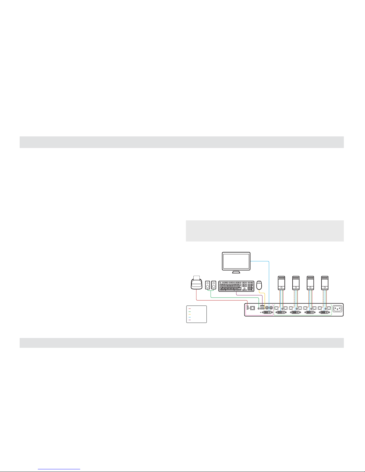
Step 1 – Connect peripherals to the KVM Console ports:
• Keyboard: Connect either a USB or PS/2 keyboard to the
corresponding KVM console keyboard port.
• Video: Connect the monitor cable to the KVM console video port.
• Mouse: Connect either a USB or PS/2 mouse to the corresponding
KVM console mouse port.
• Audio peripherals: Connect headphones / speakers to the KVM
console audio-out port.
• USB peripherals: Connect USB peripherals to the KVM console
fUSB port.
Note: Authentication devices such as smartcard and biometric readers are
enabled by default, other devices must be explicitly whitelisted – for further
information please refer to the KVM Administrator’s guide.
fUSB Cable
Audio Cable
Mouse Cable
Display Cable
Keyboard Cable
Smart-Card
Reader
Computers
CONSOLE PORTS COMPUTER/SOURCE PORTS
Audio Keyboard Mouse
Display
Page 5

4
HSL Mini-Matrix Quick Setup Guide
INSTALL ATION
SECTIONS
Table of Contents
1 3
2
Step 2 – Connect computers to the KVM Computer ports:
• Computer keyboard & mouse connection: Connect each
computer to the KVM keyboard & mouse computer port using
a USB A to USB B cable. Connect the USB A end to the
computer and the USB B end to KVM.
• Computer video connection: Connect each
computer to the KVM computer video port using
the corresponding video cable (VGA/HDMI/
DVI/DP).
• Computer audio connection: Connect each
computer to the KVM audio-in port using an
audio cable. Connect one end of the cable to
the computer’s audio-out port using the 1/8”
(3.5mm) stereo plug. Connect the other end of the
audio cable to the KVM audio-in computer port.
• Computer USB peripherals: Connect each computer to the
KVM fUSB computer port using a USB A to USB B cable. Connect
the USB A end to the computer and the USB B end to KVM.
Note: 4 channel product illustrations shown throughout this manual are
applicable to other KVM models.
Multiple Sources
Speakers
Single
Keyboard & Mouse
Single Display
PC #4
Top Secret
SECURE
KVM SWITCH
SECURE
KVM SWITCH
Page 6

5
HSL Mini-Matrix Quick Setup Guide
INSTALL ATION
SECTIONS
Table of Contents
1 3
2
Step 3 – Power ON your system:
• Power ON the monitor: Make sure that the monitor is turned ON
prior to powering ON the KVM.
• Power ON the system: Connect all peripherals and computers to
the KVM prior to powering it up. Power ON the KVM by plugging it
to the AC wall outlet. By default, after product power-up, the active
channel will be computer #1, indicated by the applicable front panel
push button LED lit.
Note: Power ON self-test: As the product powers-up it performs a self-test
procedure. In case of self- test failure for any reason, including jammed buttons,
the produc t will be Inoperable. Self-test failure will be indicated by abnormal LED
behavior – for further information please refer to the KVM setup guide.
Step 4 – Reset to Factory Defaults
Reset to factory defaults clears the device settings and restores the
device to its original configuration.
• System reset, clears behavioral characteristics such as mouse
settings and display presets. Type { L CTRL | L CTRL | F11| r } key
combination.
• Complete reset: clears all device settings and resets to factory
defaults. From the Terminal menu select the “Reset to Factory
Defaults” option (refer to terminal mode guide).
Important Notes:
1. Always use the left control key (CTRL) unless otherwise specified.
2. Keyboard shortcut keys are to be pressed sequentially
3. Do not use the numeric keypad for toggling shortcuts unless other wise
specified.
4. ALL KEYBOARD SHORTCUTS REFER TO QWERTY KEYBOARDS. In case a nonqwerty keyboard is in use, keep using the QWERTY layout.
`~1!2@3#4$5%6^7&8*9(0)-_=
+
Tab
Q W E R T Y U I O P
[{]
}
Caps
A S D F G H J K L
:
;
‘
“
Shift
CtrlCtrl Alt Alt
Delete
Enter
\
|
Shift
Ctrl
é
ç ê è
0
1 2 3
4 5 6
7 8 9
-
+
Num
Lock
Enter
=
/
*
,
Insert
Delete
Home
End
Page
UP
Page
Down
Z X C V B N M
?/>.<
,
Page 7

6
HSL Mini-Matrix Quick Setup Guide
OPERATION
SECTIONS
Table of Contents
1 2
3
Operating the KVM
Front Panel Push-Buttons
• Following power up, the default channel is #1.
• Select any other channel by pressing the appropriate front panel
push button.
• The mouse cursor will be positioned at the center of the selected
computer display.
• The currently selected channel is indicated by the illumination of
the appropriate push-button.
Filtered USB Port (fUSB) Operation
• This product is equipped with a fUSB port which by default
accepts only USB authentication devices (smart card / biometric
readers).
• When a legitimate USB device is connected to the fUSB console
port the fUSB status LED on the front panel is illuminated with
steady GREEN.
• When a non-legitimate USB device is connected to the fUSB
console port the fUSB status LED on the front panel is illuminated
with steady RED.
• Once switching between channels, for example from channel #1
to channel #3, the USB device which is connected to the fUSB port
is automatically switched accordingly. This is indicated by channel
#3 fUSB LED turning steady GREEN.
• When switching to a channel that has no USB fUSB connection,
the fUSB Port remains mapped to the last channel that had a fUSB
connection.
• Press the freeze USB button on the front panel to assign the fUSB
port to a specific computer. Freeze USB prevents switching the
fUSB port while the keyboard, video, mouse and audio peripherals
are switched between computers. Freeze USB is useful for various
scenarios, for instance, when a USB smart card reader must
remain mapped to a certain computer.
Page 8

7
HSL Mini-Matrix Quick Setup Guide
OPERATION
SECTIONS
Table of Contents
1 2
3
Smoothly switch between computers (Virtual Display Technology)
• Automatically switch control from one computer to another by
dragging the mouse cursor over the computer’s display border.
• Shared peripherals (Keyboard, Audio, USB) switch to the next
computer without having to press any buttons once the mouse is
passing the display border.
To activate VDT mode:
• Change the mouse mode to Absolute by typing L CTRL | L CTRL
| F11 | c
• Enable Video Follow Mouse by typing L CTRL | L CTRL | f
Switch between computers:
• Press the front panel buttons to manually switch control from one
computer to another.
• Use cursor navigation switching (VDT) to automatically switch
between computers by dragging the mouse cursor over the
computer’s display border. Once the mouse is passing the display
border, shared peripherals (Keyboard, Audio, USB) switch to the
next computer without having to press any buttons.
PC #1 PC #2
Screen border
Mouse cursor movement path
To deactivate VDT mode:
• Change the mouse mode to Relative by typing L CTRL | L CTRL
| F11 | b
• Disable Video Follow Mouse by typing L CTRL | L CTRL | f
Notes:
• VDT is disabled by default. Resetting the product to factory defaults,
disables VDT.
• Multi-monitor computers require driver installation, currently available
only for Windows (http://highseclabs.com/support/downloads/?rid=19).
Page 9

8
HSL Mini-Matrix Quick Setup Guide
OPERATION
SECTIONS
Table of Contents
1 2
3
Interchangeable KVM-to-KM Functionality
• In KVM mode (default) one display, keyboard, mouse, USB and
audio peripheral set is shared between all computers.
• In KM mode each computer is connected to a separate display
while keyboard and mouse are shared.
To change from KVM to KM mode:
• Disconnect the Display from the KVM Console Port.
• Connect each computer directly to a separate display while
keeping the keyboard, mouse, USB and audio peripherals
connected to the KVM.
• Change the mouse mode to Absolute by typing L CTRL | L CTRL
| F11 | c
Keyboard
Audio
Computers
Mouse
Display
Secure KVM Switch
Keyboard
Secure KM Switch
Audio
Computers
Mouse
Displays
Page 10

9
HSL Mini-Matrix Quick Setup Guide
OPERATION
SECTIONS
Table of Contents
1 2
3
Switch between computers in KM mode:
• Press the front panel buttons to manually switch control from one
computer to another.
• Use cursor navigation switching (VDT) to automatically switch
between computers by dragging the mouse cursor over the
computer’s display border. Once the mouse is passing the display
border, shared peripherals (Keyboard, Audio, USB) switch to the
next computer without having to press any buttons.
PC #1 PC #2
Screen border
Mouse cursor movement path
To change from KM to KVM mode:
• Connect a Display to the KVM Console Port.
• Connect each computer to its corresponding KVM Computer
Video Port.
• Change the mouse mode to Relative by typing L CTRL | L CTRL
| F11 | b
Note: Resetting the product to factory defaults, disables the KM mode.
Page 11

10
HSL Mini-Matrix Quick Setup Guide
OPERATION
SECTIONS
Table of Contents
1 2
3
Keyboard shortcut options
# Action Description Keyboard
1 Toggle bet ween mouse mod es
(Absolute) - L CTRL | L CTRL | F11 | c
(Relative) - L CTRL | L CTRL | F11 | b
2 System Reset to fac tory defaults L CTRL | L C TRL | F11 | r
3 Enter Terminal-Mode L CTRL | R C TRL | t
4 Video Fo llow Mouse (toggle ON/OFF)* L CTRL | L C TRL | f
* (Use in conjunction with Absolute mouse mode to switch sources by moving the mouse
accross the display border - in KVM mode)
Page 12

©2017 All rights reserved. HSL logo and product names are trademarks or service trademarks of HighSecLabs Ltd (HSL). All other marks are the proper ty of their respec tive owners.
Images fo r demonstratio n purposes only. This document may contain conf idential and/or proprietar y information of HSL Cor poration, and it s receipt or posses sion does not convey any
right to repro duce, disclose its contents, or to manufacture or sell any thing that it may describe. Reproduction, disclosure, or use without specific authorization from HSL Corporation
is strictly prohibited.
Highseclabs.com
 Loading...