

High Score PACMAN MULTI KIT Installation Instructions Manual

An EXCLUSIVE kit brought to you by - www.HighScoreSaves.com
PACMAN MULTI KIT INSTALLATION INSTRUCTIONS
Steps for a successful install of your online or offline high score save
kit -
Ensure your gameboard is working 100% before installing kit
Ensure power to game is off before removing your gameboard from
cabinet
Label any connectors that you will be disconnecting. This will make
reinstalling easier once kit is on gameboard
Note which way your edge connector is on. We suggest taking
pictures to help you remember!
Work in a well lit area on your workbench
The Pacman Multi Kit contains -
1 Pacman Multi Kit
1 CPU 40 Pin flat cable
1 GFX multiboard (for location 5E)
3 Prom multi-Boards (for locations 7F, 4A and 1M)
1 28 pin socket
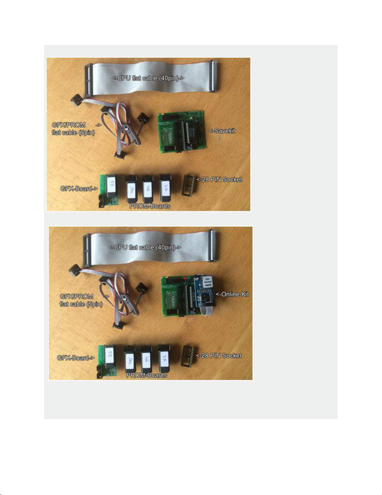
Offline Multi Kit
Online Multi Kit
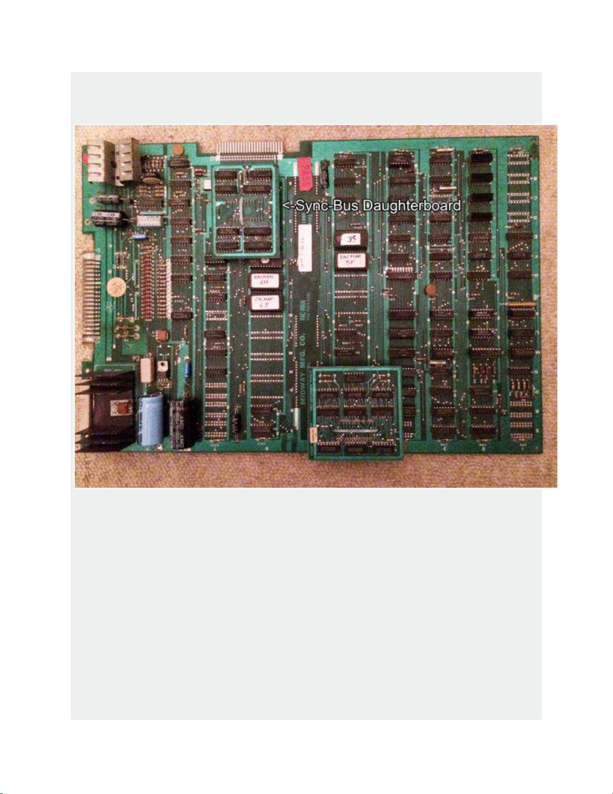
1. Remove the game board and locate the sync bus daughter board
(some versions of Pacman have a custom IC instead of the syncbus
daughter board, in this case skip step 3)
2. Cut the cable tie and carefully remove the sync bus daughter board
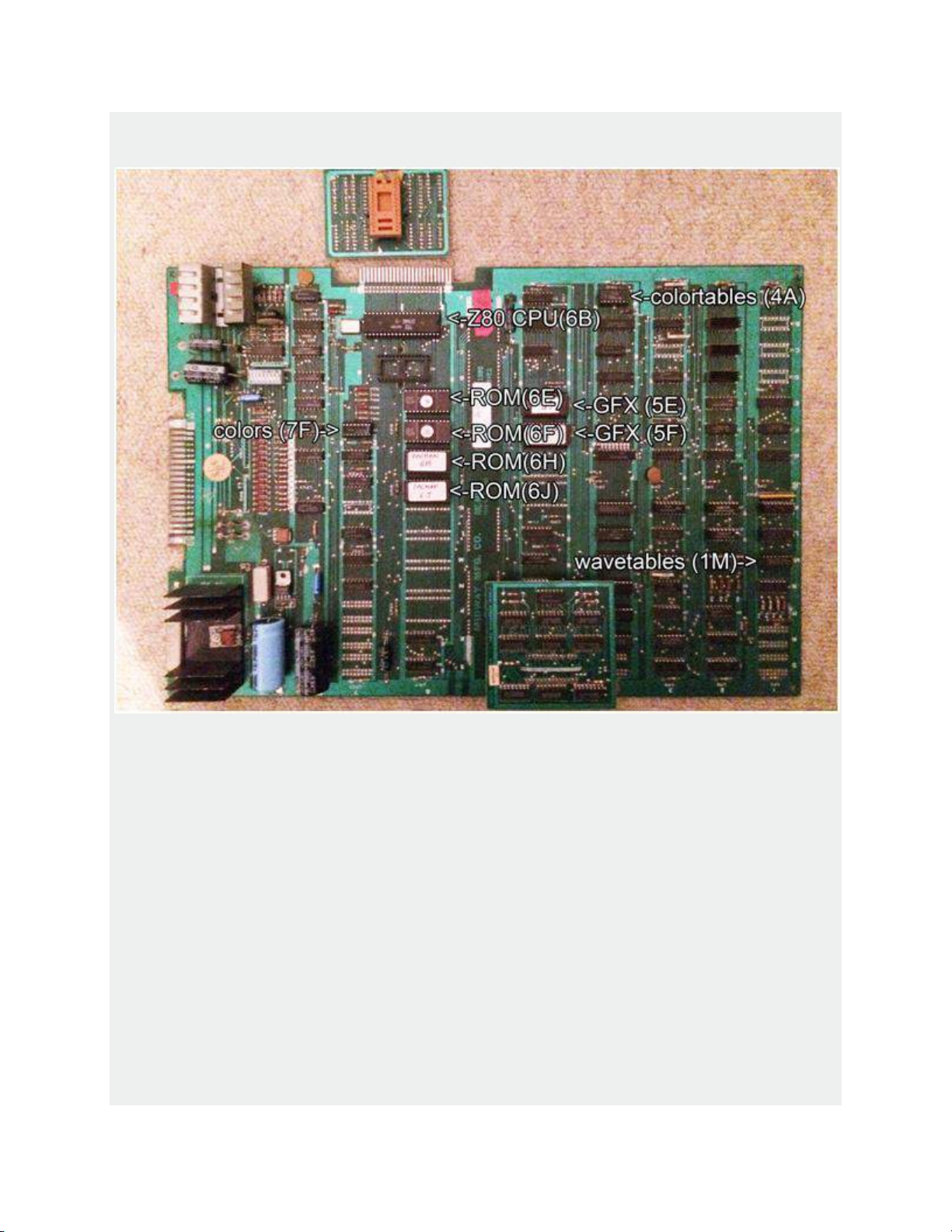
3. Remove all program roms (location 6E-6P (on the pic above, only 6E-6J
are filled with roms)
4. Remove all GFX-Roms at location 5E and 5F (Recommendation - label
the eproms before removing)
5. Remove the PROM at location 7F (recommendation: label the prom
before removing)
6. Remove the PROM at location 4A (recommendation: label the prom
before removing)
7. Remove the PROM at location 1M (recommendation: label the prom
before removing)
8. Remove the Z80 CPU at location 6B
(If you have a MS pacman board, remove the original 40pin flat cable)
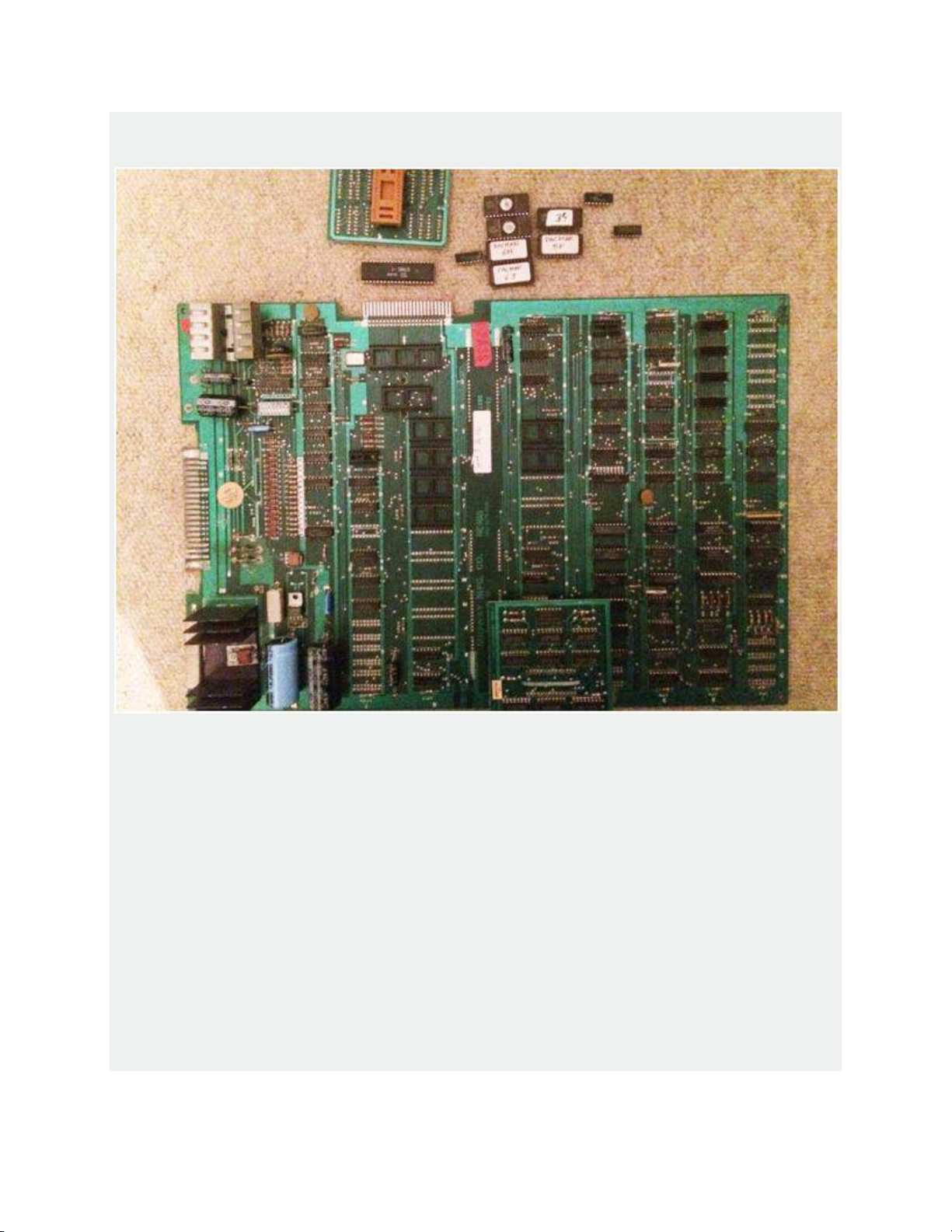
After removing all the parts above, the the pcb should look like this -

9. Carefully insert the 40pin flat cable connector (DIL) into the socket of the
Z80 CPU
- make sure that the flat cable points to the CPU edge connector (see pics
below)
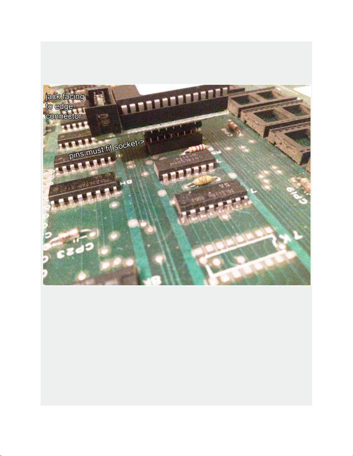
10. Insert the PROM Board labeled with 7F in the socket located at 7F
(see pic below)
Make sure that the pins fit the socket and the 10pin jack is facing to the
gameboard edge connector
 Loading...