

Page 1
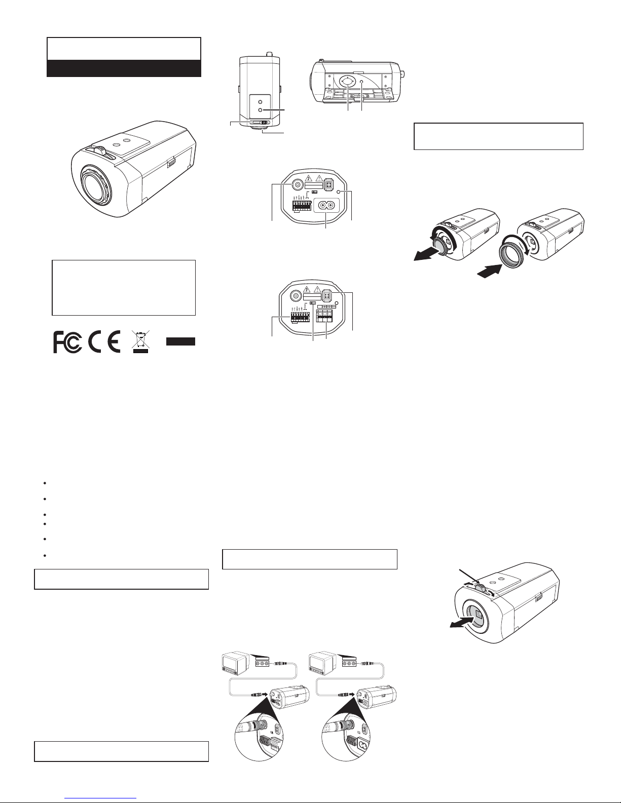
Name and Function of Parts
Top View Side View
OSD Menu
Navigation
Pad
OSD Menu
Control
Key
SET
Control Key
Rear Panel Connections
(AC mains)
Rear Panel Connections
(AC/DC low voltage)
Important Notes
Safety Information
Installation and servicing must only be carried out
by qualified personnel.
To avoid risk of damage or electric shock, do not
attempt to service this product or open the chassis.
This product contains no user-serviceable parts.
Low voltage cameras must be powered from a UL
listed class 2 power supply.
For outdoor use, please employ an IP65 (or better)
certified protective housing.
Mains cameras are not evaluated by UL.
CAUTION: To prevent risk of fire or electric shock,
do not expose this product to rain or moisture.
This camera is designed for indoor general-purpose
CCTV applications only. Do not expose to extreme
conditions such as temperatures outside the range of
-10ºC~50ºC (14ºF~122ºF).
This camera must be used in a clean, dry, dust-free
environment unless enclosed in an IP65 (or better)
certified housing.
This product is intended for security and surveillance
CCTV applications. It must be installed and maintained
in accordance with good installation practices.
Electromagnetic Compatibility (EMC)
NOTE: This is a class B product. In a domestic
environment this product may cause radio interference.
The manufacturer declares that this product is compliant
with EMC directive 89/336, and Low Voltage Directive
LVD 73/23 EEC, conforming to the requirements of
standards EN 55022 for emissions, IEC801 parts 2, 3 and
4 for immunity, and EN 60065 for electrical equipment
safety.
Connecting to a Power Supply
Connecting
Mains Power Supply: This camera operates directly
from the mains supply and is supplied with a detachable
power supply cord. The operating voltage is
100~250VAC
Low Voltage Power Supply: This camera operates
between 11~28 VDC and 20-29VAC. Connections are
indicated above the terminals on the rear panel of the
camera. The power supply must be a UL listed class 2
type.
NOTE: The typical power consumption of a camera is
less than 5 Watts.
The power LED on the rear panel is lit when the camera
is connected to a power source.
Connecting to a TV / Video
Connect a video coaxial cable terminated with a 75 Ω
BNC connector to the BNC socket labeled VIDEO OUT.
Connect the other end of the cable to the VIDEO IN
socket of your video or television equipment.
RL
VIDEO
RL
VIDEO
Mounting Your Camera
Your camera can be mounted from the top or bottom,
either on a bracket or tripod. The mounting points accept
standard photographic mounting bolts (1/4" BSW or 20
UNC).
The mounting bracket must be capable of supporting
the camera and the lens.
Should the lens be substantially heavier than the camera,
it is recommended to use the mounting point on the lens
itself.
NOTE: Ensure the bracket anchors and mounting
surface can support the load of the camera and
bracket.
Installing Lenses
Before installing a lens, you must first remove the lens
cover from the camera. If mounting a C-Mount lens,
attach the spacer ring to the camera.
Installing Fixed and Manual Lenses
1. If using a C-mount lens, slide the back focus adjustment
fully to the left with the lens facing towards you (see
Setting the Focus).
2. Screw the lens on to the camera.
3. Ensure the electronic iris and automatic gain control are
both ON.
4. If the lens has an iris, open this fully.
5. If the lens has a focusing ring fitted, set it to infinity (∞)
and then adjust the back focus.
6. If the lens has an iris, close according to the required
depth of field.
Focus
Adjust
Lens
Mount
Bracket
Mount
Power
LED
Power
Socket
BNC Composite
Video Output
VIDEO
RISK OF ELECTRIC SHOCK
DO NOT OPEN
DC LENS
NOR.t
POWER
Ƃ 100 - 240VAC 50/60Hz
VIDEO LENS
CAUTION
- +- +
AI Lens,
Lamp & Data
Connections
RS485
Switch
Power
Input
Terminal
DC Lens
Connector
VIDEO
RISK OF ELECTRIC SHOCK
DO NOT OPEN
DC 12V
AC 21V
DC LENS
NOR.t
POWER
GND
VIDEO LENS
CAUTION
- +- +
Setting the Focus
To adjust the image focus, there is a back focus
adjustment mechanism located at the front of the camera,
above the lens. If a C-Mount lens is to be used on the
camera, the supplied adaptor ring should be mounted to
the camera first. Failure to do this may cause damage to
the IR Cut filter mechanism and CCD.
Use the following procedure to adjust the focus:
1. Unscrew (loosen) the back focus adjustment lock
screw.
2. Slide the focus adjustment to the left (if facing the lens)
to move the CCD sensor away from the back of the
lens or to the right to move the CCD sensor towards
the back of the lens.
3. Tighten the screw to lock the back focus adjustment in
place.
Lock Screw
This camera is the ideal solution for
security and surveillance needs. It provides
excellent quality even in low-light
conditions, features zone blocking to
safeguard your privacy, and remote control
via an RS485 port.
High Resolution
True Day/Night Box Camera
QUICK START GUIDE
RoHS
R
Page 2
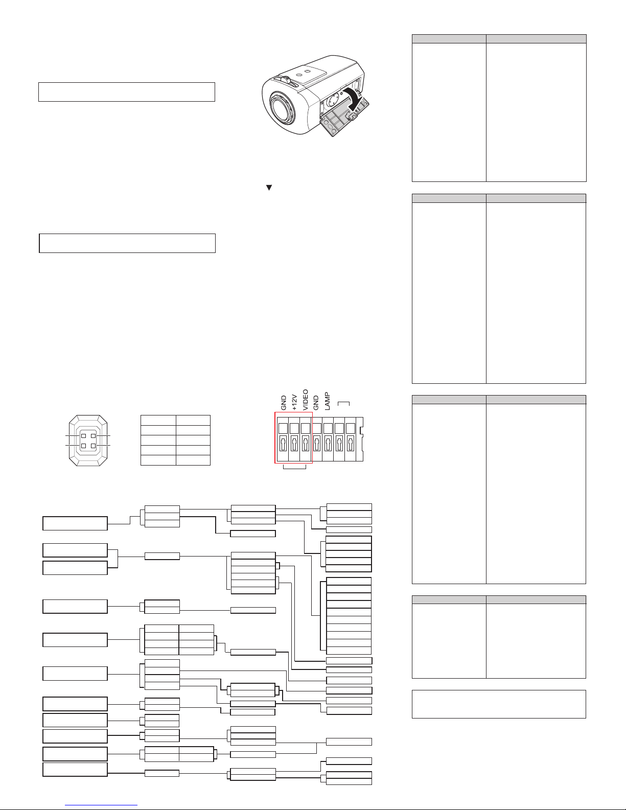
Menu Navigation
Open the panel on the side of the camera to access the
Navigation Control Pad and Set Key.
Installing a Video Drive Lens
CAUTION: The maximum load for this type of lens
must not exceed 50mA.
Installing a Direct (DC) Drive Lens
CAUTION: The maximum load for this type of lens
must not exceed 25mA.
DAY/NIGHT
DELAY TIME
BURST
D/N LEVEL
LOW
STANDARD
HIGH
AUTO/ON
60 Sec
30 Sec
20 Sec
10 Sec
05 Sec
SETTING
CHROMA
APERTURE
AGC
BRIGHT
SHUTTER SPEED
GAMMA CORR
AES
1/100K
1/10K
1/4K
1/2K
1/1K
1/500
1/250
1/120(1/100)FLK
1/50 (1/60)
WB PUSH
1-9
LEVEL 1-9
LEVEL 1-15
COLOR ROLLING
LEVEL
BF
ZONE 4
ZONE 6
ZONE 3
ZONE 2
ZONE 1
OFF
ZONE 5
LEVEL
LEVEL
MWB
ATW-EX
ATW
WB PUSH
B GAIN LEVEL
R GAIN LEVEL
00-FFh
LOCK/PUSH ON
LINE LOCK
INTERNAL
V-PHASE
ON
OFF
ON
OFF
FLASH
POSITION
TEXT
OFF/ON
ZONE 3
ZONE 2
ZONE 1
ZONE 4
SET ZONE
SETTING
BAUD RATE
ADDRESS
0-999
19200 bps
9600 bps
DAY
NIGHT
AUTO
BURST
Camera OSD Menu
DAY MODE
NIGHT MODE
LENS
BLC
WHITE BALANCE
SYNC
MIRROR
TITLE
PRIVACY ZONE
RS485
Specifications
NTSC PAL
1/3 Format Interline CCD Sensor
768(H) x 494(V) 752(H) x 582(V)
NTSC 2:1 Interlace PAL 2:1 Interlace
H:15750Hz V:59.94Hz H:15625Hz V:50.0Hz
-10°C~50°C / -20°C~60°C
<90% Non-Condensing
BNC 75Ω unbalanced
20~29VAC
11~28VDC
4.5W Max
3Ø Green LED on Rear Panel
3pin Push Lock Terminal Block on Rear
4pin Connector on Rear
CS Mount, Change C Mount by Adaptor
CS Mount 12mm +/- 1.0mm, Adjust by screw
1/4” Top and Bottom
73mm(W) x 63mm(H) x 122mm (L)
IRIS Connector
Power Source
General
Image Size
Pixel Element
Scanning Frequency
Operation/Storage Temperature
Relative Humidity
Output Terminal
AC Supply
DC Supply
Power Consumption
Power Indicator
Video Drive
DC Drive
Lens Mount
Back Focus Adjust
Mounting Hole
External Dimension
Line Lock
Functional Specification
Exposure Control
AES
MES
Auto IRIS Control
Video IRIS Output
DC IRIS Output
White Balance
Auto White Balance Range
Manual White Balance Range
Day & Night
IR Lamp Trigger
AGC Boost
Color Killer
SYNC System
Phase Adjust Range
Frequency Range
NTSC PAL
Auto Detection for AES (Fixed Iris), DC Iris or
Video Iris Lenses.
Auto Luminance Control
1/60 (1/50) ~ 1/100000 sec Max.
8 Step: 1/60(1/50), 1/120(1/100), 1/500,
1/1000, 1/2000, 1/5000, 1/10000
Video Drive / DC Drive Separate Output
600mV Vpp (100IRE Video Output)
1.2V at 85Ω Impendance
Auto White Balance/ Push White / Manual
White Balance
Standard Range: 2700K ~ 9700K
Extended Range: 2500K ~ 15000K
1 Preset; R gain and B gain Adjustable
Optical Low Pass Filter Removable (Auto
Detect) <Fuzzy 30 IRE ~80 IRE>
External Relay Contact input for IR switching
Enhanced AGC Gain to Max. 30dB
Fuzzy / ON / OFF
INT / Line Lock
0°C~270°C
60Hz +/- 1Hz 50Hz +/- 1Hz
Video Specification
Normal Mode
TDN Mode
Day Mode
Night Mode
Video Output
95 IRE
40 IRE
Close IRIS
AGC Max Gain
AGC Default Gain
White Clip
Pedestal Level
SYNC Level
Burst Level
Aperture
Mirror
Gamma Compensation
Gamma Crosses Point
Gamma Block Level
Bright Level
Chroma Level
NTSC PAL
540 TV Line
570 TV Line
0.6Lux @ F=1.2 (50IRE Video Output)
0.1Lux @ F=1.2 (40IRE)
1.0Vpp 75Ω BNC unbalance
50dB
38dB
38dB
30dB
24dB
120 IRE Max
7.5 +/- 2.5 IRE
40 +/- 2 IRE
40 +/- 2 IRE
15 Step, Level adjustable 0 IRE~15 IRE
(r=0.45 @ 100 IRE output)
ON / OFF
9 Step
55 IRE ~ 65 IRE
10 IRE ~ 15 IRE
15 Step
9 Step
Resolution
Minimum Illumination
S/N Ratio
Function Control or Adjustment
Exposure Control
Color Killer
BLC
Auto White Balance
AGC Gain Control
SYNC System
V-Phase
Remote Control
Address
NTSC PAL
Auto Detect
Fuzzy ON / OFF
6 Areas with adjustable levels
2700K~9700K / 2500K~15000K
18dB~30dB Linear Adjustment
INT / LL Switchable
0°~270°
* RS-485, Two way communications
000~999
Setting Video Drive Lens Level
1. Access the menu and select:
DAY MODE > SETTING > AGC.
2. Note the current value. Then set to ”1” and exit the
menu.
3. Adjust the lens level potentiometer for the correct
exposure. (This can be achieved manually, or by using
an oscilloscope or level meter to set the output of the
camera to 1V peak-peak).
4. Return the AGC to the previously noted setting.
Press and hold the SET Key on the side of the camera to
access the main menu
Use the Up/Down buttons on the Contol Key to select the
desired menu option. If a sub menu is available, this is
indicated by
Pressing the SET key will open the sub-menu.
Values are changed using the Left/Right buttons.
Remember to select SAVE before exiting the menu or
else changes will not be implemented when the camera
is next powered up.
* RS-485
For further information on the remote RS485 control contact your
local representative
LENS - BF Function
This function provides the installer with a simplified method
of adjustment of optical back focus. When used with an
auto iris lens, this function will automatically fully open the
IRIS of the lens and swtich the camera to AES (auto
electronics shutter) mode whilst the BF option is selected.
In the case of a manual lens, this function will automatically
switch to AES.
Move the cursor to LENS with the Control Key, select BF
and press SET key. Whilst in BF mode “ Press SET for
return” is displayed on the monitor.
Adjust the optical back focus for optimum focus then press
SET key to return to the top menu. ( Please refer to section
“Setting the Focus” ).
3. Access the menu and select LENS > BF. (See LENS BF Function)
4. If a focus ring is fitted on the lens, set it to infinity (∞)
and then adjust the back focus.
5. Exit the BF menu to return to normal operation.
3. Access the menu and select LENS > BF. (See LENS BF Function)
4. If a focus ring is fitted on the lens, set it to infinity (∞)
and then adjust the back focus.
5. Exit the BF menu to return to normal operation.
1. If using a C-mount lens, fit the C-mount adaptor ring
and slide the back focus adjsutment fully to the left with
the lens facing towards you (see Setting the Focus).
2. Fit the lens to the camera and connect it to the DC lens
socket, as defined by the pin assignments in Figure 1.
1. If using a C-mount lens, fit the C-mount adaptor ring
and slide the back focus adjsutment fully to the left with
the lens facing towards you (see Setting the Focus).
2. Fit the lens to the camera and connect it to the Video
Lens connector, as defined by the pin assignments in
Figure 2.
Pin Number
DC Drive
Pin 1
Damp-
Pin 2
Damp +
Pin 3
Drive
-
Pin 4 Drive +
DC LENS
1
2
4
3
Figure 1
VIDEO LENS
- +- +
RS485
Figure 2
 Loading...