

Page 1

TEL: (203)-634-3900 FAX: (203)-238-2425
If you are having problems using this product, please call Highpower Technical Support
at 203-634-3900. We are here to help and we appreciate your business!
MODEL 8000 DOOR CONTROLLER WITH POWER OVER ETHERNET (POE)
TABLE OF CONTENTS
EMAIL: [email protected]
WEB: WWW.HIGHPOWERSECURITY.COM
HARDWARE MANUAL
VERSION 1.0.1
DOCUMENT NUMBER: 980-8000-1.0.1
CONTROLLER DESCRIPTION.................................................................................................2
KEY FEATURES .......................................................................................................................3
8000 CONTROLLER BOARD ...................................................................................................3
BOARD PHOTO AND LAYOUT .............................................................................................3
BOARD CONNECTIONS BLOCK DIAGRAM.........................................................................4
TYPICAL POE CONNECTION DIAGRAM .............................................................................5
NOTICE OF INSTALLER QUALIFICATION...........................................................................6
POWER REQUIREMENTS........................................................................................................6
FLEXIBLE POWER SUPPLY OPTIONS................................................................................6
DETAILS ABOUT POWER OVER ETHERNET FEATURE....................................................6
STAND ALONE OPERATION...................................................................................................7
ADDITIONAL I/O FEATURES................................................................................................8
DESCRIPTION.......................................................................................................................8
SCHEDULES..........................................................................................................................8
REAL TIME CLOCK ...............................................................................................................9
ADVANCED STAND-ALONE FEATURES................................................................................9
SOFTWARE INTERFACE......................................................................................................9
SCHEDULING PROGRAMMING .........................................................................................10
AUTOMATIC UNLOCKING USING SCHEDULES...............................................................10
HOLIDAYS ...........................................................................................................................12
FIRST-PERSON-IN FEATURE.............................................................................................13
FORCED LOCKDOWNS......................................................................................................13
FORCED DOOR UNLOCK (PASSAGE MODE)...................................................................14
NORMAL DOOR OPERATION.............................................................................................14
HARDWARE FEATURES........................................................................................................15
ON BOARD JUMPER FUNCTIONS.....................................................................................15
REMOTE RELEASE.............................................................................................................15
READER PORTS .................................................................................................................15
ADVANCED READER PORT FEATURES..............................................................................16
PROXIMITY (WIEGAND) FORMATS (BOTH READER PORTS).........................................16
DETAILS ABOUT USING WIEGAND DATA ........................................................................17
Page 2

READER PORT 1 SPECIAL FEATURES ............................................................................17
BARCODE SYMBOLOGY SUPPORT..............................................................................17
MAGSTRIPE INPUT.........................................................................................................18
DETAILS ABOUT BARCODE INPUT...............................................................................18
PDI MODE........................................................................................................................18
BARCODE NORMALIZATION..........................................................................................18
MASKING INPUT DATA.......................................................................................................18
CUSTOM WIRING DIAGRAMS AND UNIQUE APPLICATIONS ........................................... 19
TROUBLESHOOTING ISSUES ..............................................................................................20
WARRANTY INFORMATION..................................................................................................20
APPENDIX A – MEMORY RECORD SIZE CALCULATIONS..............................................20
APPENDIX B – COMPATIBLE POE SWITCHES ................................................................21
APPENDIX C – WIEGAND BIT SIZE TABLE.......................................................................22
APPENDIX D – TESTED COMPATIBLE READERS ...........................................................23
PROXIMITY READERS....................................................................................................23
BAR CODE READERS.....................................................................................................23
MAG-STRIPE READERS.................................................................................................23
APPENDIX E: ELECTRICAL SPECIFICATIONS ................................................................... 24
APPENDIX F: CONNECTOR DESCRIPTIONS ......................................................................25
CONTROLLER DESCRIPTION
The 8000 Series is a door controller designed for one or two door operation. It provides the
installer with the latest advancements in Ethernet communications and Power-Over-Ethernet
technology. The 8000 controller has been specifically designed for use with the Highpower
Management System (HMS), which is a SQL based database and control program for the Windows
.NET platform. The 8000 can also run in stand-alone configurations without software. When using the
HMS software the 8000 is networked to provide a rich control environment that allows customers to
manage alphanumeric card IDs, schedules, and holidays and to generate reports based on system
activity.
The 8000 controller is used in conjunction with external card reader(s) to create a secure two-piece
access control solution. The card reader inputs of the 8000 controller support a wide variety of reader
types including:
• Barcode readers (Wiegand Data on Port 1 or Port 2 or Un-encoded Barcode Data on Port 1)
• Proximity Readers (Wiegand Data on Port 1 and Port 2)
• Magnetic Stripe Readers (ABA Data on Port 1 and Port 2)
• Wiegand Card Readers (Wiegand Data on Port 1 and Port 2)
Communications from the controller to the HMS software is accomplished through either RS-232 port
(serial) or more commonly through the built-on Ethernet port, which supports the 802.3af POE
standards.
The Power-Over-Ethernet features of the controller are unique in that the controller allows the installer
to power the controller itself, two card readers and two electric strikes simultaneously when the total
current draw of the connected devices is fewer than 900mA @ 12VDC (around 11 Watts).
This document will describe the features of this controller for simplified installation and setup.
Page 2 of 26
Page 3
KEY FEATURES
• RS-232 and Ethernet Networking with 802.3af Power-Over-Ethernet built on board.
• Two-Door Operation with Request to Exit and Door Position Switch monitoring.
• One-Door model available.
• Flash-Based Non-volatile memory 512K for each reader.
• 25 Schedules with 8 periods (when used with HMS software).
• Automatic door unlocking and relocking cycles.
• Adjustable memory structure – Memory structure is adjusted based on length of longest
• Reader inputs can be configured to accept different signal types including Wiegand and
• Reader inputs can mask data to include or exclude digits from user ID on a hardware level.
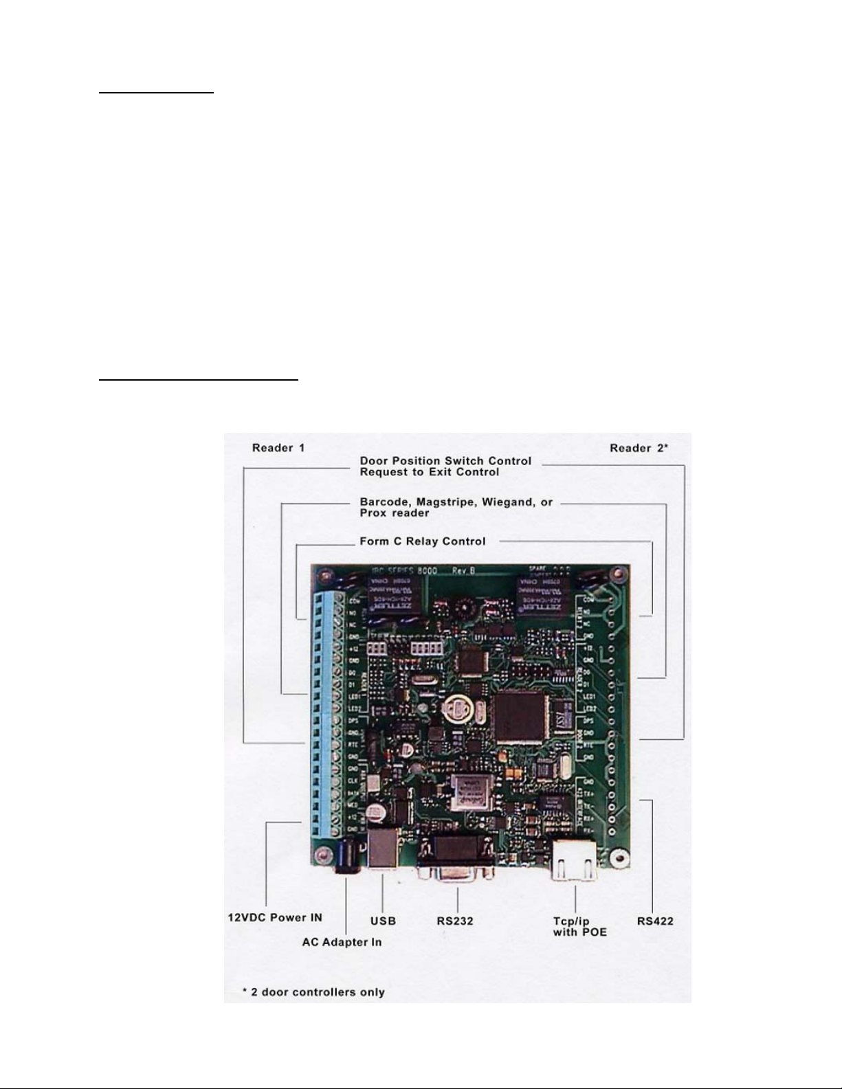
8000 CONTROLLER BOARD
BOARD PHOTO AND LAYOUT
user ID in order to maximize memory space for IDs (automatically configured when using
HMS software).
ABA. Reader Input 1 can also accept barcode symbologies (including Code 3 of 9, I 2 of 5,
Interleaved I 2 of 5, Codabar, UPC A, EAN13 and Code 128 barcode types).
Page 3 of 26
Page 4
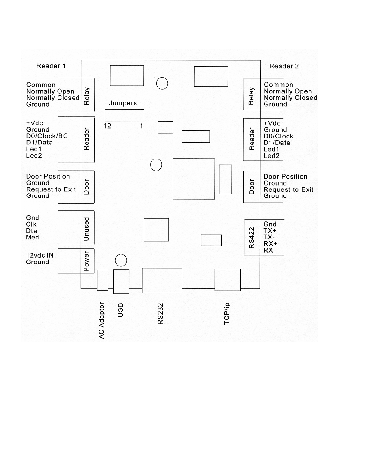
BOARD CONNECTIONS BLOCK DIAGRAM
Page 4 of 26
Page 5
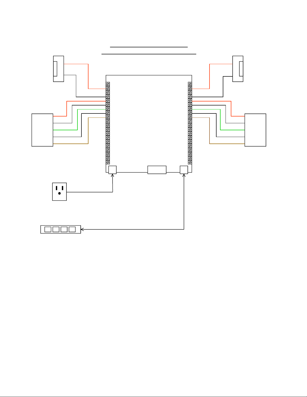
TYPICAL POE CONNECTION DIAGRAM
12 VDC
ELECTRIC
STRIKE
DOOR 1
Typical Power-Over-Ethernet
Configuration using Electric Strikes.
(+12 VDC)
(+12 VDC)
12 VDC
ELECTRIC
STRIKE
DOOR 2
WIEGAND
READER
DOOR 1
+12 Vdc
Ground
Data 0
Data 1
(Ground)
RED
BLACK
GREEN
WHITE
LED
BROWN
AUXILIARY PLUG
IN WALL
TRANSFOMER
12 VDC
(USE WHEN POE
IS UNAVAIABLE)
Common—Relay 1
Normally Open—Relay 1
Normally Closed—Relay 1
Ground
+ V dc (note jumper JP6)
Ground
Data 0 / Clock / BCin
Data 1 / Data
Green LED
Red LED
Door Position Switch 1
Ground
Request To Exit 1
Ground
Ground (OPTIONAL)
For future use.
For future use.
For future use.
+12 VDC (OPTIONAL)
Ground (OPTIONAL)
Common—Relay 2
Normally Open—Relay 2
Normally Closed—Relay 2
(note jumper JP7) + V dc
Door Position Switch 2
RS-422 TX + (OPTIONAL)
RS-422 TX - (OPTIONAL)
RS-422 RX + (OPTIONAL)
RS-422 RX - (OPTIONAL)
Ground
Ground
Data 0 / Clock
Data 1 / Data
Green LED
Red LED
Ground
Request To Exit 2
Ground
Spare
Ground
-
(Ground)
RED
BLACK
GREEN
WHITE
BROWN
WIEGAND
READER
DOOR 2
+12 Vdc
Ground
Data 0
Data 1
LED
NETWORK HUB
(WITH OPTIONAL P.O.E.)
Page 5 of 26
Page 6

NOTICE OF INSTALLER QUALIFICATION
The items listed in this manual may require the services of an individual who is trained in the
application and installation of life safety equipment. All wiring must be in compliance with current NEC
guidelines.
POWER REQUIREMENTS
FLEXIBLE POWER SUPPLY OPTIONS
The controller is powered using either 12VDC connected to one of the terminals on the board (12vdc IN
or ac adapter IN) or through using Power-Over-Ethernet via the Ethernet connector.
There is internal voltage regulation on the controller board, so a 13.8 Volt supply, or an unregulated / or
regulated plug in wall adapter that can provide the required power is acceptable to use.
8000 Controllers equipped with the POE feature can get power directly through the CAT 5 networking
cable through a POE network switch, so a local power supply is typically not required. There are
applications where an external power supply may be required over the POE. Please read the section
below concerning Power Over Ethernet for more information concerning this.
The controller power requirement (for the board only) is:
Without Onboard Ethernet: 150 mA @12 VDC
With Onboard Ethernet: 350 mA @12 VDC
When using a power supply you must make sure that the power supply will support not only the power
requirements of the controller board, but also any readers and locks that you are powering off of the
controller.
Additionally, there are jumpers on the controller board for powering the door strike(s) directly from the
board. When you are powering the strikes from the board, DO NOT connect a power supply to the
common relay contact. The controller sources the power for the strike directly from the power supply
which is supplying power to the controller.
If you decide to power the strikes directly through the board, you must make sure that the total power
usage for both strikes combined is not more than 700ma. This is the limitation for strike power through
the board, whether powering the board from an external plug in adaptor or through POE.
Note that the door strikes can always be powered separately by changing jumpers and using the relay
as a dry contact. In this case, the relay contacts should be limited to a 5 Amp load. To use the relay as
a dry contact remove jumpers 11 and 12 which connect relay 1 and relay 2 contacts to the power
supply on the board. DAMAGE TO THE BOARD WILL OCCUR if you leave these jumpers in and
provide power directly to the relay common line.
DETAILS ABOUT POWER OVER ETHERNET FEATURE
The 8000 is fully IEEE 802.3af compliant. Power can be supplied over the Ethernet data lines, or on
one of the unused pairs. Normally, the power is supplied by an Ethernet switch but it can also be
supplied by a power inserter. A list of tested and recommended power inserters can be found in the
appendices.
The power supplied over the Ethernet cable can also supply the electric strike or maglock connected to
the door. An additional supply typically is not needed for the door lock. Power for the lock mechanism
is taken directly from the controller board, eliminating the need for a separate power supply for the lock
mechanism.
Page 6 of 26
Page 7

Note that because of POE specification limitations, the maximum combined power that can be supplied
to all connected readers and strikes, is 700mA @12vdc. Do not exceed this power limitation or damage
could occur to the controller board.
When using POE, the typical installation will require installing either a POE switch or a power inserter
near the Ethernet switch. Category 5 cable can be used to connect to the controller board for lengths of
up to 100 meters.
Battery backup can be implemented by using a UPS at the switch or power insertion point instead of
traditionally having a battery backup at each controller box. There is no need when using POE to
provide battery backup at the controller location. It is highly recommended that you install a UPS on
your switch equipment to insure constant uninterrupted controller operation.
Note that an 8000 controller with POE does not have to be powered over the Ethernet. You can still
power it with a standard supply. If you intend to use POE but cannot initially install the POE switch or
power inserter, the 8000 can still be installed using a power supply temporarily. The 8000 should not be
connected to a POE source and a local power supply at the same time. Doing this could damage the
controller.
You can power external devices like electric strikes and maglocks directly from the POE interface by
setting appropriate jumpers. The power insertion jumper(s) must be on for the POE power to pass
through the relay to the lock mechanism. See the jumper configuration section below for setting the
appropriate jumper settings.
STAND ALONE OPERATION
The stand-alone mode operates without the need of a real-time computer connection. This is the
mode that the controller is typically configured to and this mode is used in conjunction with the HMS
software. When a card is read, the controller performs a search for the card number in memory. If
the card number is found and the card’s schedule is valid, access is granted. Cards are normally
entered into the controller by transferring the card data from a PC. You can, however, enroll the
cards locally at a connected reader using control cards. If cards are enrolled locally, there is no
need for a computer connection at all other than for the initial programming.
There is an audit trail feature in the controller while operating in the stand-alone mode. Whenever a
valid card is read, the card number, along with the date and time, is stored in the controller's
memory. This audit trail data can be transferred to a computer at any time and is automatically
retrieved when using the HMS software. Optionally, cards which are read but not granted access
can also be stored in the audit trail to log invalid entry attempts. Audit trail data is stored in nonvolatile flash memory and is not lost if power is lost. A separate audit trail is stored for each of the
two doors (readers).
When a valid card is found, the appropriate output relay is triggered for the pre-programmed time,
allowing the door to be opened. When the door is closed, the controller can automatically re-lock
the door rather than wait until the full time period has elapsed (anti-tailgating feature) when the
controller is used in conjunction with a Door Position Switch (DPS). Anti-tailgating is a
programmable option.
The controller supports scheduling in the stand alone mode. Schedules tell the controller which time
of day a card has access for. A card number can be associated to one or a series of schedule
times, allowing multiple access times during an individual day. When using the HMS software, 25
schedules are provided, each schedule having 8 periods.
Page 7 of 26
Page 8

ADDITIONAL I/O FEATURES
A "Request to exit" switch can be connected to an input on the controller for remote door unlocking.
When the switch is engaged, the controller will trigger the relay for the pre-programmed time,
allowing the door to open. The Request to exit can operate in both modes, stand-alone and online.
DESCRIPTION
Stand-alone mode is the most commonly used mode in the controller. This mode is used by the HMS
control software. In the stand-alone mode, the controller operates independently from a computer, but
allows a computer to make changes to the controller memory.
All card numbers which have access through the door must be loaded into the controller's memory.
This can be done either by loading in the data from a PC, or by enrolling each card at the reader locally.
The preferred method will depend on the number of cards that you need to enroll and whether you want
to use the scheduling features provided in the controller. Cards which are enrolled locally at a reader
cannot use the scheduling features, so if you need to use schedules then card data must be
downloaded into the controller via software.
The number of cards that can be stored in the controller depends on the size of the cards. Memory in
the controller is pre-allocated and therefore you can adjust the number of allowable cards in the system
based on your card data size. A list of the total number of cards which can be stores is provided in the
Appendices.
SCHEDULES
In the stand-alone mode, schedules are supported in the controller. Schedules allow you to specify the
times of day that an employee has access for. There are 199 unique schedules that can be
programmed into the controller, each schedule representing the allowable times for employee access
for 7 days (Monday thru Sunday). When using the HMS software, these 200 schedules are grouped
into schedules and periods, allowing for 25 schedules each with 8 periods (shifts).
Holiday schedules can also be entered in. The holiday schedule in the system is loaded in as day “8”.
Cards which are enrolled at a reader are enrolled with no schedule, meaning they will have access at
all times. This means that if you enroll cards at the reader you cannot specify a specific schedule.
Currently, you should not use the enrolling feature at the reader if you are also using the HMS software.
Each schedule specifies the start time and end time that access is allowed.
As an example, 0700 thru 1529 represents 7:30 in the morning till 3:29 in the afternoon. At 3:30 in the
afternoon and after, the employee will not have access.
It is possible to associate schedules in the controller. When you associate schedules, you are linking
multiple schedules together.
For example, let us say that you want to allow access between 7 in the morning and noon, and then
again between 1 pm and 4 pm. You would enter in two different schedules in the system, one for the 7
to noon, and another from 1 to 4, and then link them together. The result is a schedule which allows
access from 7 to noon, and then from to 4. From noon until 1259, access is not allowed. When using
the HMS software, the software will link sets of 8 schedules together automatically to form 25
schedules each with 8 intervals (shifts).
Page 8 of 26
Page 9
There is an audit trail in the controller which will record each transaction that occurs in the reader. The
audit trail can be turned on or off. Whenever a card is read, the date and time, along with the card data
is stored in the audit trail. This data can be retrieved from the controller at any time. This audit trail data
is stored in a circular buffer to prevent the latest audit information from getting lost if the audit memory
space is full. Note that there are separate audit trail logs for each reader connected to the controller.
The HMS software will retrieve this audit trail information for each reader and use the information to
generate reports with the HMS reporting facility.
REAL TIME CLOCK
The time is set in the 8000 using the HMS software or via typed command. Time is accurate to about 1
minute per year. It is suggested that you update the time on a periodic basis. The real time clock is
updated every second. Schedule times, holiday periods, and other real time events are also checked
every second. Audit trail data is accurate to the second.
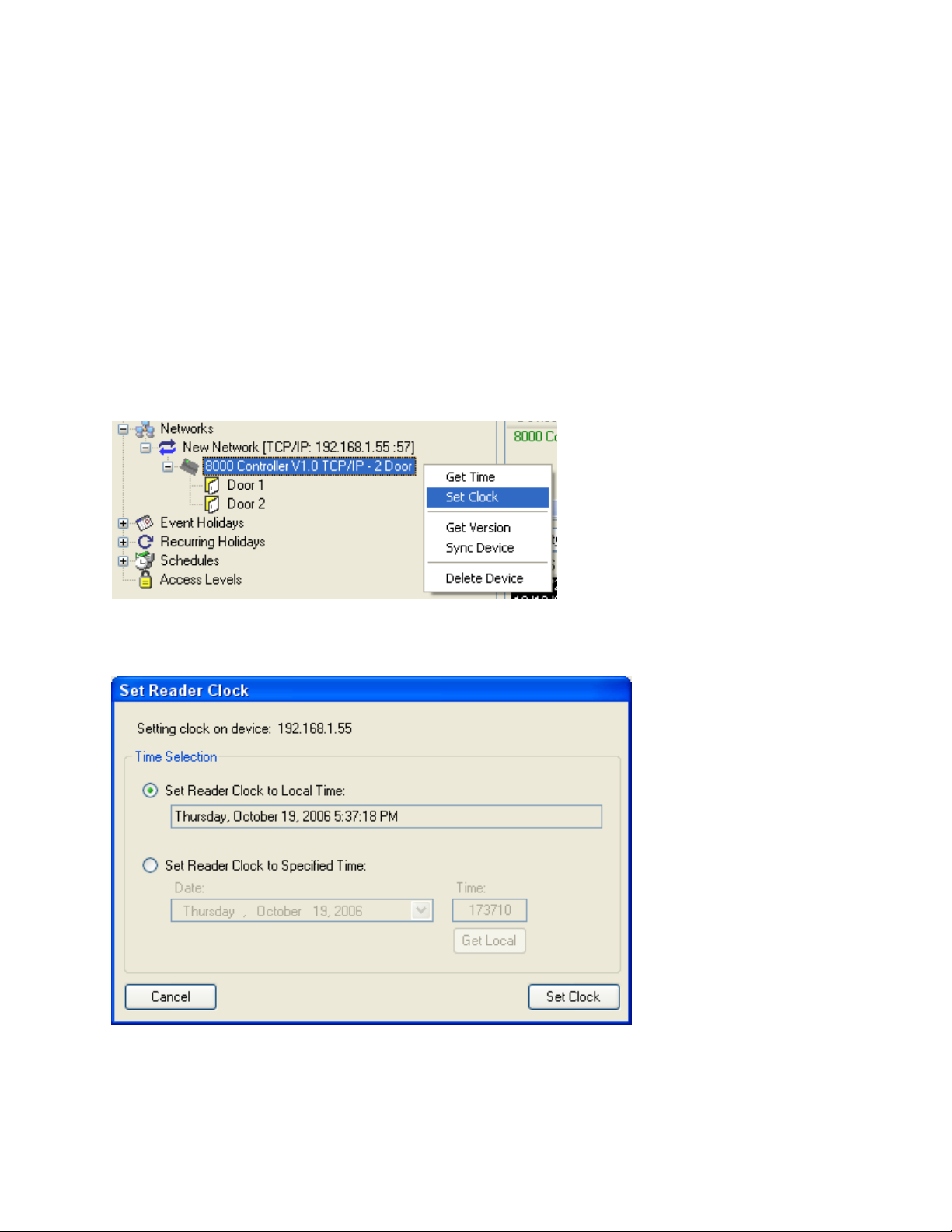
To set the current time in the system using the HMS software, right click on the controller that you wish
to set the time on. Left click on “Set Clock”.
HMS allows you to set the clock to different times which is important if the Controllers are in different
time zones:
ADVANCED STAND-ALONE FEATURES
SOFTWARE INTERFACE
Adding cards and changing settings in the controller is mainly done using the HMS software. You do
have the option however, to add cards to the controller by using control cards. In doing this, you do not
Page 9 of 26
Page 10
need software for programming, but you will not be able to easily use the advanced scheduling and
other advanced features of the controller.
SCHEDULING PROGRAMMING
The controller contains memory for the loading of up to 199 schedules. These are identified as
schedule numbers 001 through 199. Each loaded schedule consists of 8 entries total. Seven
schedules for the 7 days of the week and 1 entry which is used for holidays. Each entry contains a
start time and an ending time that access is allowed for. If an entry for a particular day is not entered,
then access is not allowed for that day. The HMS software automatically groups these 200 schedules
into 25 schedules each with 8 intervals (shifts).
Entered schedule times are inclusive, not exclusive. If you want to allow access from 7 in the morning
until noon (don't allow access after noon), then the entered times are 0700 thru 1159. This means that
at 1159 you can still unlock the door, but at 1200 noon you cannot. To refer to midnight, you use 0000.
Schedules cannot cross midnight. To cross midnight you enter in a time period for the first day, and
then a time period for the second day. In order to allow two time periods in the same day, you must
associate two schedules together. This is handled automatically when using the HMS software.
Schedule 0 is a reserved schedule. This schedule is an open schedule, meaning access is allowed at
all times. Any card number entered into the system with schedule 0 is automatically allowed access at
all times, all days, including holidays. Cards which are enrolled locally at the readers are also entered in
with schedule 0. This means they have access at all times.
AUTOMATIC UNLOCKING USING SCHEDULES
Page 10 of 26
Page 11
The 8000 contains a feature to allow either door to be unlocked during specific times of the day. You
may want, for example, to keep the door open during shift changes, or during lunch periods. The HMS
software can use your scheduling information to lock and unlock the doors automatically.
Schedule number 200 is a special function schedule in that the controller will automatically unlock the
door when the schedule time starts for that particular day. HMS will associate multiple schedules
together (starting with schedule 200) in order to unlock the door for multiple periods of the day.
During the unlock period, card scans are still allowed, but they have no effect on relay operation since
the relay is already actuated. If the audit trail is being used, the card scans will be stored as usual.
The unlock schedules will optionally work on holidays using the "day 8" schedule times. At the
beginning of the holiday period, the relay is automatically locked as usual, and then unlocked when the
schedule 200, day 8 unlock start time is reached.
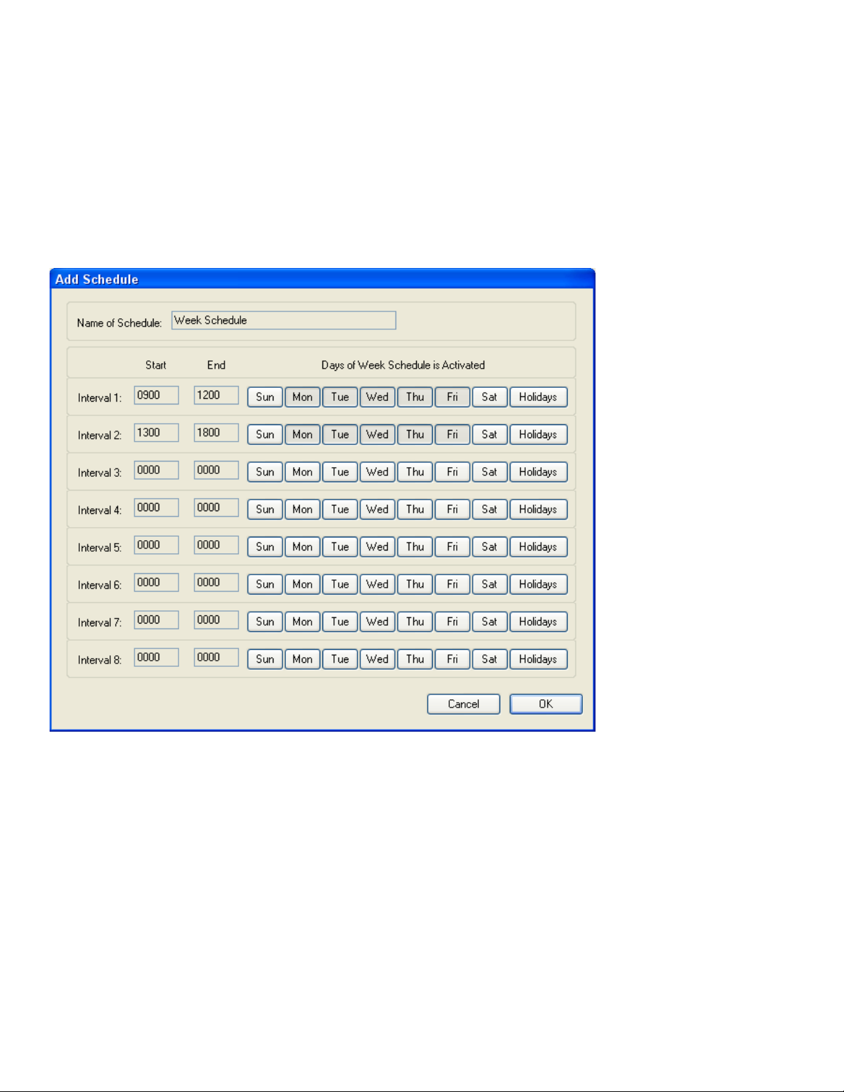
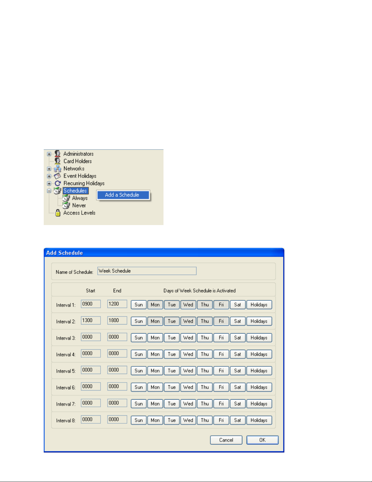
Adding a schedule with the HMS software is accomplished by right clicking on Schedule in the
configure tree and selecting “Add a Schedule”.
Once you have clicked Add a Schedule, then the schedule screen pops up, which allows you to set up
your schedule times:
Page 11 of 26
Page 12
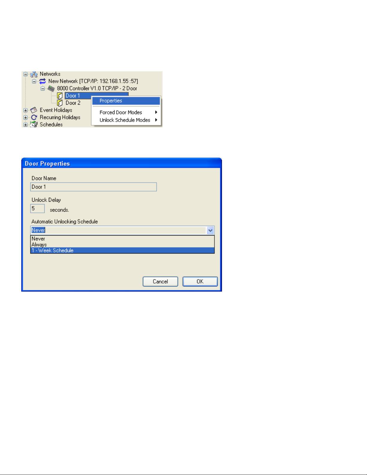
Once you have configured your schedule, you must tell HMS to use the schedule as an unlocking
schedule. To do this, right click on the door that you wish to work on an unlock schedule and select
“Properties”:
Once you click on properties, the door properties window will be shown. Pick the schedule that you
have created to use as an unlock schedule:
Once you select “OK” the doors will work on the selected unlock schedule once the system has been
Synced.
Note that Unlock periods are not implemented if the system is in a Forced Lockdown or Forced Open
mode (described in later section).
HOLIDAYS
The controller supports both recurring holidays and non-recurring holiday periods. Recurring holidays
are holiday periods that recur for the same date every year (like New Years Day or Christmas). Nonrecurring holidays do not recur from year to year, or the dates change, and therefore need to be
programmed in every year (Special events, Labor Day, etc).
During a holiday period, the controller automatically turns off the relay, and switches to the day 8
schedule. Day 8 is therefore considered the "holiday schedule". During the holiday schedule, even if
an employee normally has access for that specific day, he will not have access unless access is
permitted under the day 8 schedule or if he has been entered in with schedule 0, which allows access
at all times.
Page 12 of 26
Page 13
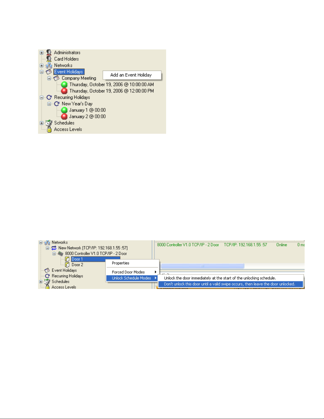
Non-recurring and Recurring holiday periods are specifically handled in the configure tree of the HMS
software. Right-click on either “Event Holidays” or “Recurring Holidays” in order to Add a holiday to the
system:
FIRST-PERSON-IN FEATURE
First-Person-In is a feature which allows a door unlock period to be delayed until at least one valid card
is read. This function is normally enabled to make sure that if the door is to be unlocked, that there is at
least someone around when it does unlock.
If the First Person In option is turned on, then when an unlock period is scheduled to start, the door will
remain locked. When the first valid read occurs, the door is then unlocked and remains open until the
end of the unlock period. A valid read is any card which normally would have been accepted if the
system was not in the unlock period.
The first-person-in features is specifically handled in the configure tree of the HMS software. In HMS,
right click on the appropriate door in the configure tree, select “Unlock Schedule Modes” and then click
on “Don’t unlock this door until a valid swipe occurs, then leave the door unlocked.”
To disable the First-Person-In feature, select “Unlock the door immediately at the start of the unlocking
schedule.
FORCED LOCKDOWNS
Either door connected to the 8000 can be locked down at any time using the HMS software, and also
with the reading of a special lockdown card. During the lockdown period, only cards entered in with a
schedule 0 will have access.
The forced lockdown can be turned off using the HMS software or also by scanning in the "End forced
mode" control card.
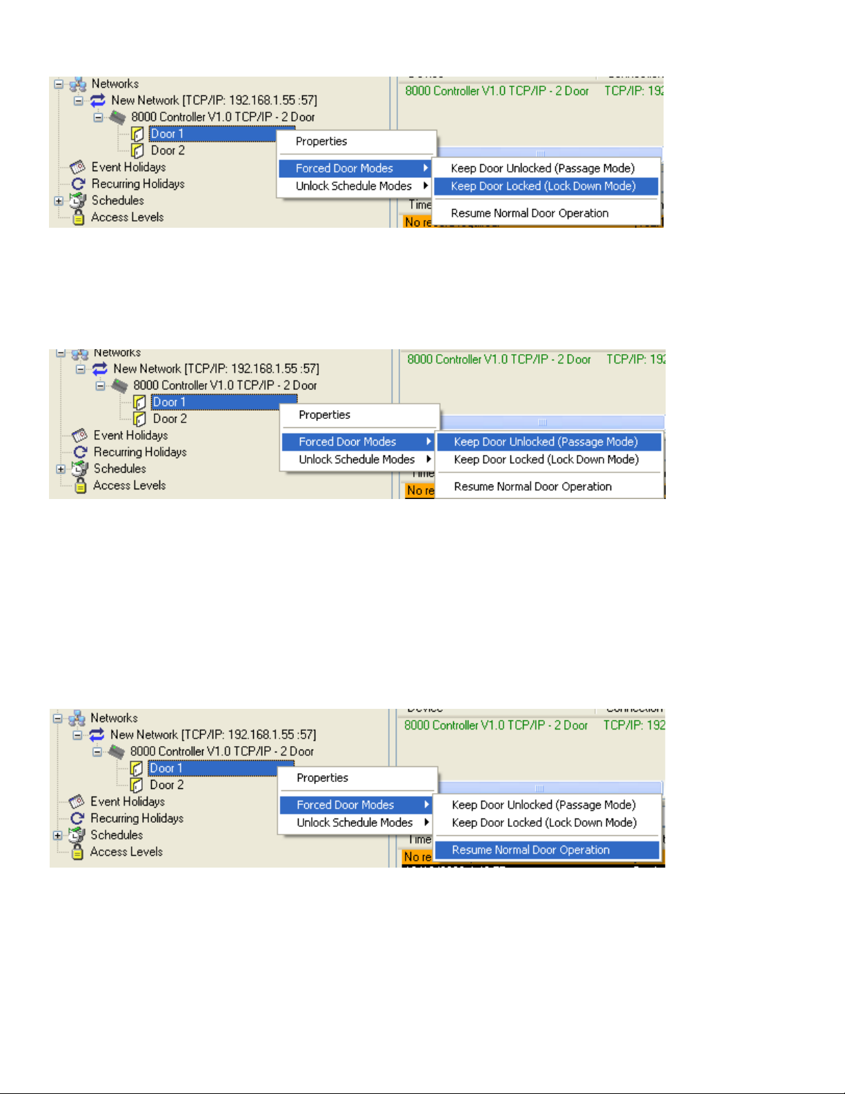
In the HMS software, right click on the appropriate door in the configure tree, select “Forced Door
Modes” and click “Keep Door Locked (Lock Down Mode)”.
Page 13 of 26
Page 14
FORCED DOOR UNLOCK (PASSAGE MODE)
Passage mode (Forced "opens" of the door) can be achieved using the HMS software or by presenting
the "force open" control card to a reader. In the HMS software, you right click on the appropriate door
in the configure tree, select “Forced Door Modes” and click “Keep Door Unlocked”.
The door will remain open until the door is put back into either normal operation or into a forced
lockdown. An "End forced mode" card can also be scanned to enter forced lock open mode.
NORMAL DOOR OPERATION
Normal door operation returns a particular door to normal operation from Forced Lockdown or Passage
Mode. The door will resume operating with schedules and operating with valid cards.
In the HMS software, you right click on the appropriate door in the configure tree, select “Forced Door
Modes” and click “Resume Normal Door Operation”.
Page 14 of 26
Page 15

HARDWARE FEATURES
3
F
n
,
ON BOARD JUMPER FUNCTIONS
JUMPER
JP1 When removed and powered up, controller enters “Learn” mode.
JP2 RS-232 or USB active port selection (on models with USB).
JP3 TCP/IP or RS-422 active data port selection (on models with TCP/IP).
JP4 Selects which port data is sent out to in online mode. On selects (TCP/IP/RS-422). Off selects (RS-2
JP5
JP6
JP7
JP8 Reserved for future use. THEY MUST BE LEFT OPEN.
JP9 Reserved for future use. THEY MUST BE LEFT OPEN.
JP10 Used to connect 12V power to the reader outputs. JP6 and JP7 must be removed when JP10 is con
JP11
JP12
REMOTE RELEASE
The Remote Release Terminals provide a connection for external switches that are used to trigger Door
1 or Door 2. These switches are normally open switches, that when closed, cause the respective door
to unlock. The doors will remain unlocked for their programmed unlock cycle times.
READER PORTS
The controller has two Ports for reader connection.
NAME
READER PORT 1
(+Vdc) (+5V) or (+12V) Reader Supply Voltage (Selected by Jumpers 6 and 10)
Ground DC Supply Ground
D0/Clock/BC Port 1 Wiegand Data 0 / ABA Clock Input / Barcode Input
D1/Data Port 1 Wiegand Data 1 / ABA Data Input
LED 1 Port 1 Green LED Control Line Output
LED 2 (Optional based on reader) Port 1 Red LED Control Line Output
READER PORT 2
(+Vdc) (+5V) or (+12V) Reader Supply Voltage (Selected by Jumpers 7 and 10)
GND DC Supply Ground
D0 / Clock Port 2 Wiegand Data 0 / ABA Clock Input
D1 / Data Port 2 Wiegand Data 1 / ABA Data Input
LED 1 Port 2 Green LED Control Line Output
LED 2 (Optional based on reader) Port 2 Green LED Control Line Output
FUNCTION
Used to place the RS-232 port into a known state. Forces the controller to start up with the RS-232
port set at 9600 baud, 8 data bits, no parity. Remove this jumper and power up to make the RS-232 t
online port with the above settings. Used when the ports have been changed to some unknown state
Both of these jumpers should be on in order to provide 5V power to the readers. JP10 should be OF
these jumpers are connected.
Jumper supplies power from the POE supply directly to the common terminal of Relay 1. When open,
1 works as a dry contact set.
Jumper supplies power from the POE supply directly to the common terminal of Relay 2. When open
2 works as a dry contact set.
FUNCTION
Page 15 of 26
Page 16

ADVANCED READER PORT FEATURES
Both reader inputs of the 8000 support Wiegand and ABA. Reader input 1 additionally supports
barcode symbologies. Readers can use either 12VDC or 5VDC power and can be powered off the
controller in both powered mode and using POE. Power is supplied directly from the controller for
the readers.
The 8000 supports the connection of an undecoded barcode reader directly on the reader #1
connection ONLY. It you have a 2-door controller, and need barcode reading for both doors, a
decoded barcode reader with magstripe emulation or wiegand interface, can be used for the 2nd
reader or for both readers. Contact Highpower for assistance when picking readers with a barcode
input.
Wiegand and Proximity readers should have a standard Wiegand data output (Data 0 and Data 1
signals). Most, but not all, proximity readers have this type of output. Compatible models include
readers from many popular brands including and reader from Farpointe Data, HID Corporation,
Indala and AWID. Barcode readers include readers from International Bar Code (IBC). The inputs
of the 8000 have been tested with the Farpointe Data reader line specifically. Highpower can
provide you with a Farpointe reader for your application.
Magnetic stripe readers should have an undecoded magstripe output, known as "clock and data"
signals. If you need a dual-technology single reader, then any of the Magbar or Smart Prox readers
from International Barcode, with ABA, Wiegand, or wand emulation outputs can also be connected
to the controller. Multiple readers may be connected to the same reader input, as long as the
readers have open collector outputs. If this multiple readers on one port is used, only one reader
can transmit to the controller at a time.
Most 8000’s are in the two-door configuration. The 2-door controller supports the connecting of 2
separate readers. Each reader is treated individually and operates independently of the other. In the
stand-alone mode, each reader uses its own memory space for accessing valid ids, and for the
audit trail. In the online mode, both readers share the same output. Reader styles can be mixed.
You do not have to use the same technology reader on each input. For example, you can have a
barcode reader as reader #1, and a magstripe reader as reader #2, or you could combine
magstripe/proximity readers, etc.
PROXIMITY (WIEGAND) FORMATS (BOTH READER PORTS)
The controller supports all proximity and wiegand data formats up to 64 bits. Each individual field (site
code, id number, and optional issue code) is extracted and converted to a decimalized number,
resulting in a numeric string. This is the string that is used for comparisons in the controller while in the
stand-alone mode. In the online mode, this string is simply transmitted. The controller converts this
information into a string so that masking of the data can be achieved easily should you need to mask
out numbers from the card ID.
A special mode of the controller called open enrollment allows you to accept wiegand data without a
decimalized conversion. In this mode, all wiegand formats up to 64 bits are accepted and stored
directly with no conversion.
Three different formats are programmable, allowing the controller to accept three different card formats
for each reader. Each format is fully configurable by bit, and the extracted data can be modified by the
controller prior to comparison or transmission. Numbers can be added to the data, or deleted from the
data. See the Advanced Concepts section for more information on this topic.
Page 16 of 26
Page 17

DETAILS ABOUT USING WIEGAND DATA
The controller will accept any size wiegand input up to 64 bits. Please note that most proximity readers
output data in the Wiegand data format.
Because Wiegand data is binary, the data is normally meaningless unless it is decoded into a useful
number in some way. The industry standard for wiegand data is a 26-bit stream, consisting of a site
(facility) code of 8 bits and also a badge (id) number of 16 bits. This is also the default setting for the
controller. The largest site code that can be transmitted with 26 Bit Wiegand is value 255. The largest
ID code that can be transmitted in 26 Bit Wiegand is 65535. The controller therefore decodes 26 bit
wiegand numbers into an 8 digit string, consisting of 3 digits for the site code, and 5 digits for the id
number, by default.
In order to decode a different format, you must program the controller so that it understands the bit
structure that you will be reading. It is necessary to do this so that the controller will end up with the
correct unique id number. You must program in the starting bit position and number of bits for the site
code (if it is being used), as well as the id number. Issue codes are also supported as a separate field
and they can be decoded or ignored.
It is important to note that the controller always processes wiegand bit fields in the order of site, badge
(id), and then issue code (in the rare case where an issue code is being used). The controller will
accept any size wiegand input up to 64 bits.
When decoding numbers are read from the card, the controller will concatenate each of the three fields
in the order of site, badge, and then issue to create the actual card data number that is stored in the
controller.
For example, if you have a proximity card with a facility code of 33 and an ID of 12, and have
programmed the controller to decode the site code to a 3 digit number, the id field to a 6 digit number,
and to ignore the issue code, the resulting number after decoding will be 033000012.
You can program the controller to accept up to 3 different wiegand data formats, and decode them
based on the parameters you have set. It is therefore possible to mix different wiegand or proximity
cards together in the controller. The controller will automatically discriminate them based on their bit
lengths.
It is also possible to mask the wiegand input (omit or add numbers in certain positions from the read
results). Characters can be added to or deleted from the decoded number using one of the input masks
(described later).
Backward bit structures may also be handled by the controller. Some proximity cards contain site codes
and id fields that are encoded backwards with the least significant bit first, rather than last. It is possible
for the controller to read these bit streams and decode the proper number.
READER PORT 1 SPECIAL FEATURES
BARCODE SYMBOLOGY SUPPORT
The 8000 controller supports Wiegand and ABA (also called clock-and-data) on both reader ports.
Additionally, Reader port 1 has some additional unique features in that it can also read unencoded
barcode signals. The controller supports barcode symbologies through reader port 1 only. The
following barcode symbologies are supported:
• Code39
• Interleaved 2 of 5
Page 17 of 26
Page 18

• Industrial 2 of 5
• Standard 2 of 5
• Codabar
• UPC A
• EAN 13
• Code 128
The maximum number of barcode characters that can be decoded by the controller is 22. This includes
start and stop characters and check digits. The controller can be programmed to auto-discriminate
Kronos barcodes, which are normally 17 or 18 digits long. In this mode, the id is extracted from the
entire Kronos string, and the remaining information is ignored. The controller can also be programmed
to extract the PDI from a military/CAC barcode. This extraction yields a 9 digit number (typically the
SSN). There are a number of programming options that affect the way barcodes are read and
processed. These options can be found under the Advanced Concepts section. Barcode data can also
be masked (omission of digits in barcode) and reformatted (numbers added to the string) on the
hardware level. Note that the controller supports the direct connection of an undecoded barcode
reader ONLY ON READER PORT 1.
MAGSTRIPE INPUT
Both the Track 1 and Track 2 character sets are supported by the controller. Separator character
translation is also supported, as well as B and C start sentinels for the Track 2 character set. Note that
magnetic stripes on tracks normally use the Track 2 character set and is fully supported.
Magnetic stripe data can also be reformatted using the masking commands (see Advanced Concepts).
DETAILS ABOUT BARCODE INPUT
The controller can decode numerous barcode symbologies. For all supported symbologies, it is
possible to prefix and suffix barcode data with up to 5 characters. This prefix and suffix is in addition to
the ability to add and delete characters via the masking commands.
Start and stop characters may also be included, along with check digits and scan direction indicators.
These items are normally only used when in the online mode; however they can be used in the standalone mode as well.
The controller also has advanced barcode decoding options, which are useful when there is writing
before or after the barcode, or there are extraneous bars in the barcode.
PDI MODE
When using the 8000 on Port 1 with an unencoded reader, the 8000 can automatically extract the PDI
from military and Common Access Card (CAC) barcodes. The PDI is extracted to a 9-digit number. This
number, on most cards, is the user's SSN.
BARCODE NORMALIZATION
In rare cases, if you are reading barcodes, you may have information on the card immediately to the left
or right of the barcode, which can interfere in the controller's ability to automatically decode the
barcode. The 8000 has an option for you to "normalize" the barcode, by selecting which part of the data
is to be decoded as a barcode.
MASKING INPUT DATA
The 8000 supports a number of masking parameters, including character insertion, deletion, and
selection. Character insertion allows you to add any sequence of characters to the input data at any
Page 18 of 26
Page 19

location. Character selection allows you to select only those characters that you want. Unselected
characters are deleted. There are separate masking tables for each type of input.
For example, if you are using 2 different sets of proximity cards, 26 bit and 34 bit, with different site
codes on the 34 bit cards than the 26 bit cards, and want to keep the site codes the same, you can
program the controller to ignore the site codes on the 34 bit card, and then use the masking commands
to add in the appropriate site code so that the site codes are the same as the 26 bit cards.
CUSTOM WIRING DIAGRAMS AND UNIQUE APPLICATIONS
Highpower can provide design services for you application including wiring diagrams, installation
procedures, and system integration. We offer turnkey solutions for your security requirements. Please
feel free to contact Highpower directly for integration services.
Page 19 of 26
Page 20
TROUBLESHOOTING ISSUES
This section describes troubleshooting information that is discovered through technical support calls
with our customers. Highpower attempts to update this section on a regular basis with solutions to
commonly asked technical support questions. Contact Highpower at 203-634-3900 with technical
questions.
Problem Description
Nothing currently reported.
WARRANTY INFORMATION
Thank you for choosing a Highpower product! The Highpower Security Products, LLC Door Controller
Model 8000 is manufactured to the highest quality standards to provide years of dependable service.
The Model 8000 is warranted for one year from the date of shipment against defects in parts,
workmanship and materials, when installed in accordance with instructions. Defects that occur within
this warranty period, under normal use of the product, shall be repaired or replaced with a new unit,
solely at our option. Warranty is void when product has been modified, damaged, abused, misused,
subjected to abnormal use or neglect, or subjected to harsh operating environments out of the normal
operating specifications.
No agent, employee or representative of Highpower Security Products, LLC has authority to bind
Highpower Security Products, LLC to any oral affirmation, representation or warranty, other than set
forth above. Highpower Security Products, LLC expressly disclaims all other warranties, expressed or
implied, including but not limited to any implied warranties of merchantability or fitness for a particular
purpose. “Fair-Safe” and “Fail-Secure” are definitions only. Use of these terms is not a performance
warranty, but merely a descriptive term used to characterize a design feature.
APPENDIX A – MEMORY RECORD SIZE CALCULATIONS
This appendix lists the number of available slots in the unsorted memory, sorted memory, and audit trail
log for some of the most widely used record sizes. Please note that the HMS software currently only
uses the Unsorted Memory Area for code storage, although future plans include Sorted Memory Area
support.
Record Size
4 10240 32085 16320
5 8777 27501 16320
6 7680 24064 16320
7 6826 21390 16320
8 6144 19251 16320
9 5585 17501 15360
10 5120 16042 14528
11 4726 14808 13760
12 4388 13750 13056
13 4096 12834 12480
14 3840 12032 11904
15 3614 11324 11392
20 2792 8750 9344
25 2275 7130 7936
40 1462 4583 5440
Unsorted Memory Area Sorted Memory Area Audit Log Records
Resolution
Page 20 of 26
Page 21

APPENDIX B – COMPATIBLE POE SWITCHES
The following POE power inserters have been testing and approved for use with the 8000 controller:
SonicWall Part No. 01-SSC-5531 Inserts power on unused lines.
Netgear Part No. FS108P, FS116P Switches that Inserts power on data lines.
Page 21 of 26
Page 22

APPENDIX C – WIEGAND BIT SIZE TABLE
This table shows the number of bits required to encode a specific number into wiegand. This table can
also be used to see how many characters are required to decimalize wiegand input fields.
Bits
Decimal Number Bits Decimal Number
1 1 33 8,589,934,591
2 3 34 17,179,869,183
3 7 35 34,359,738,367
4 15 36 68,719,476,735
5 31 37 137,438,953,471
6 63 38 274,877,906,943
7 127 39 549,755,813,887
8 255 40 1,099,511,627,775
9 511 41 2,199,023,255,551
10 1,023 42 4,398,046,511,103
11 2,047 43 8,796,093,022,207
12 4,095 44 17,592,186,044,415
13 8,191 45 35,184,372,088,831
14 16,383 46 70,368,744,177,663
15 32,767 47 140,737,488,355,327
16 65,535 48 281,474,976,710,655
17 131,071 49 562,949,953,421,311
18 262,143 50 1,125,899,906,842,623
19 524,287 51 2,251,799,813,685,247
20 1,048,575 52 4,503,599,627,370,495
21 2,097,151 53 9,007,199,254,740,991
22 4,194,303 54 18,014,398,509,481,983
23 8,388,607 55 36,028,797,018,963,967
24 16,777,215 56 72,057,594,037,927,935
25 33,554,431 57 144,115,188,075,855,871
26 67,108,863 58 288,230,376,151,711,743
27 134,217,727 59 576,460,752,303,423,487
28 268,435,455 60 1,152,921,504,606,846,975
29 536,870,911 61 2,305,843,009,213,693,951
30 1,073,741,823 62 4,611,686,018,427,387,903
31 2,147,484,647 63 9,223,372,036,854,775,807
32 4,294,967,295 64 18,446,744,073,709,551,615
Page 22 of 26
Page 23

APPENDIX D – TESTED COMPATIBLE READERS
Highpower strives to make the Model 8000 as compatible as possible with Wiegand devices from many
manufacturers. In accordance with this goal, we have created our Wiegand interface to automatically
detect the transmission speed of any Wiegand device connected.
As a result, we are compiling a list of Wiegand devices that have been tested with the Model 8000.
These devices include the following:
PROXIMITY READERS
All Wiegand “Pyramid” Reader Heads from Farpointe Data. (Models 300H, 500H).
Note: These are good readers for most applications.
All Wiegand “Revision E” model readers from AWID (Applied Wireless ID, Inc.)
Note: This brand is common in the security industry.
All Wiegand Readers from HID/Indala Corporation.
Note: This is the most common brand in the security industry.
BAR CODE READERS
All Wiegand models from IBC (International Bar Code, Inc.)
Note: Use the “Smart” models of IBC products when using extended bar codes.
Non-decoded model barcode readers from various brands.
MAG-STRIPE READERS
All Wiegand models from IBC (International Bar Code, Inc.)
Note: Use the “Smart” models of IBC products when using custom track configurations.
Note to Installers
having problems with a particular model of reader, we want to hear from you. Your comments are
appreciated. Please call us direct at 203-634-3900.
: If you have successfully used another brand of reader with our controller or are
Page 23 of 26
Page 24

APPENDIX E: ELECTRICAL SPECIFICATIONS
Relay(s)
Form C
Maximum Current - 6 amps
Maximum Current using POE - 700ma total
Supported Readers
Wiegand, up to 64 bits Proximity (wiegand output), up to 64 bits Magstripe (clock & data), tracks 1, 2, or
3 Barcode (undecoded output - reader 1 only)
Reader Timing
Wiegand/Prox up to 3 ms between pulses Wiegand/Prox 15us pulse width minimum Magstripe 50us
clock strobe minimum Barcode 3" - 50" per second
Symbologies
Code39, 2 of 5, 12 of 5, Ind2 of 5, Code'128, Codabar, UPCA, EAN13
Memory
512K memory available for stand-alone operations.
Communications
RS232
RS422
USB
TCP/IP (optional), 100FD operation
POE
802.3af compliant. Power can be supplied over the data lines or unused pair.
12VDC power can be supplied directly to the strike from the POE*
DPS/RTE
TTL level Door Position switch input, and TTL level Request to Exit switch input.
Power Requirements
w/o TCP/IP 100 mA @ 12 VDC
with TCP/IP 350 mA @ 12 VDC
Page 24 of 26
Page 25

APPENDIX F: CONNECTOR DESCRIPTIONS
Form C Relays
Common
Normally Open
Power for strike which is to be switched by the relay.
Connect the + voltage from your power supply for
the strike to this connection. The relay will then
connect this contact to either the normally open or
normally closed contact depending on the controller
configuration.
Note... if you are powering the strike from the POE
connection then this connector is unused.
This contact is normally open (unconnected) and
closed when the controller triggers the relay, making
a connection between this contact and the common
contact (or POE if POE is used).
Normally Closed
This contact is normally closed (connected). Power
is provided out this connection except when the relay
is triggered by the controller. This connection is
normally used to power a maglock which is powered
to keep the door closed.
Ground
Connect to the Ground on your strike only if you are
using POE to power the strike.
Notes about relay operation:
Notes about relay operation:
The maximum allowable current using the relay common input contact
current for both strikes using POE
The strikes can be operated by using the power provided over the POE circuit directly. Install Jumpers 11
and 12 to provide 12VDC power to the normally open/normally closed pair of contacts directly from the POE.
In this mode, a separate power supply for the strike is not required.
is 700ma combined.
is 6 amps. The maximum allowable
Reader Input
+VDC Power output to the connected reader. The power
can be 5VDC, or 12VDC. To provide 5VDC to the
reader, jumpers 6 and 7 must be IN. To provide
12VDC to the reader, jumpers 6 and 7 must be out,
and jumper 10 must be IN.
Ground Connect to the reader ground.
DO/Clock
For any reader with a wiegand output, connect to the
reader's DO line. For magnetic stripe readers with
clock & data output, connect to the reader's clock
line.
D1/Data/BC For readers with a wiegand output, connect the
reader's D1 line. For magnetic stripe readers with
clock & data output, connect to the Data line. For
undecoded barcode readers, connect to the
reader's barcode data output line.
LED 1 For readers with 2 LEDS, connect this line to the
reader's first led line, which is normally a red led.
Page 25 of 26
Page 26
For readers with only one bi-color led, connect this
line to the reader's bi-color led line.
LED 2 Connect this to the reader's 2nd led. If the reader
has only 1 led, do not connect this line.
DPS / RTE
Ground 2 ground connections are provided for connecting
to the DPS (door position switch) and the RTE
(request to exit).
Door Position Switch Input (DPS) This is the door position switch sensor input.
Connect this line to one side of the door position
switch, and connect the ground (above) to the
other side of the switch. When the door is closed,
a direct connection between the door position line
and the ground should be made.
Request to Exit This is a request to exit input. Connect this line to
a pushbutton switch which connects the rte line to
ground when the switch is hit. A ground contact is
provided next to this contact for connecting to the
other side of the switch.
RS-232 Port
The RS232 is a DB9 connector using Pin 2 as transmit, and Pin 3 as receive. A null modem is not required
when connecting to a PC.
Power Connections
AC adapter Connect an AC adapter capable of providing 500ma
minimum to the AC adapter jack.
12VDC supply Connect your 12VDC power supply to the 12vdc IN
and Ground contacts labeled "power" on the block
diagram.
POE When using POE, power does not need to be
supplied to the controller, as the power is supplied
through the Ethernet line.
NOTE that you can power the strikes directly through the controller using either POE or from a 12VDC
supply connected to either the 12VDC connection, or the ac adapter connection. In this case, you put in
Jumper 11 to provide direct power to relay 1, and jumper 12 to provide direct power to relay 2. The total
power consumption routed through the board must not exceed 700ma total. This includes the strike power
as well as any connected readers.
If your total power consumption (readers and strikes) will be more than 700ma, you cannot power the strikes
directly through the controller. You must use the common relay line as the power source to be switched
through the relay. Jumpers 11 and 12 must be removed from the board.
Page 26 of 26
 Loading...