


SSD7103
4x M.2 Port to PCIe 3.0x16 NVMe RAID Controller
User Guide
V1.01
1

Table of Contents
System Requirements ........................................................................................................... 3
PC Requirements ................................................................................................................ 3
SSD7103 Hardware .............................................................................................................. 3
NVMe Drive Installation: ..................................................................................................... 4
Setting up the SSD7103 for a Windows operating system .................................................... 8
Using the HighPoint RAID Management ........................................................................... 10
Starting the HighPoint RAID Management ...................................................................... 10
Verify the Controller Status .............................................................................................. 11
Creating an Array .............................................................................................................. 12
Adding Spare Disks .......................................................................................................... 16
Obtaining Logical Device Information ............................................................................. 18
Array Information &Maintenance Options: Normal Status.............................................. 19
Array Information & Maintenance Options: Critical Status ............................................. 20
Array Information & Maintenance Options: Disabled Status........................................... 21
Physical Device Information............................................................................................. 22
System Setting .................................................................................................................... 23
System Setting .................................................................................................................. 24
Password Settings ............................................................................................................. 25
Email Setting ..................................................................................................................... 25
Event Tab ........................................................................................................................... 28
SHI (Storage Health Inspector) .......................................................................................... 28
How to Enable SMART Monitoring................................................................................. 29
How to Use the Health Inspector Scheduler ..................................................................... 30
How to Create a New Verify Task .................................................................................... 31
Troubleshooting ................................................................................................................. 32
Handling Critical Arrays ................................................................................................... 33
Rebuilding Stops Due to Bad Sectors ............................................................................... 34
Critical array becomes disabled when you removed faulty disk ...................................... 34
Handling Disabled Arrays .................................................................................................. 35
Help .................................................................................................................................... 37
Table 1.HRM Icon Guide ................................................................................................... 38
Table 2. RAID Level Reference Guide ............................................................................... 41
HighPoint Recommended List of Hard Drives ................................................................... 42
Contacting Technical Support............................................................................................ 42
2
System Requirements
PC Requirements
System with an empty x16 PCIe 3.0 slot
(Please refer to the SSD7103 compatibility list.)
Windows 10 and Windows Sever 2016 or later
Linux Kernel 3.10 later
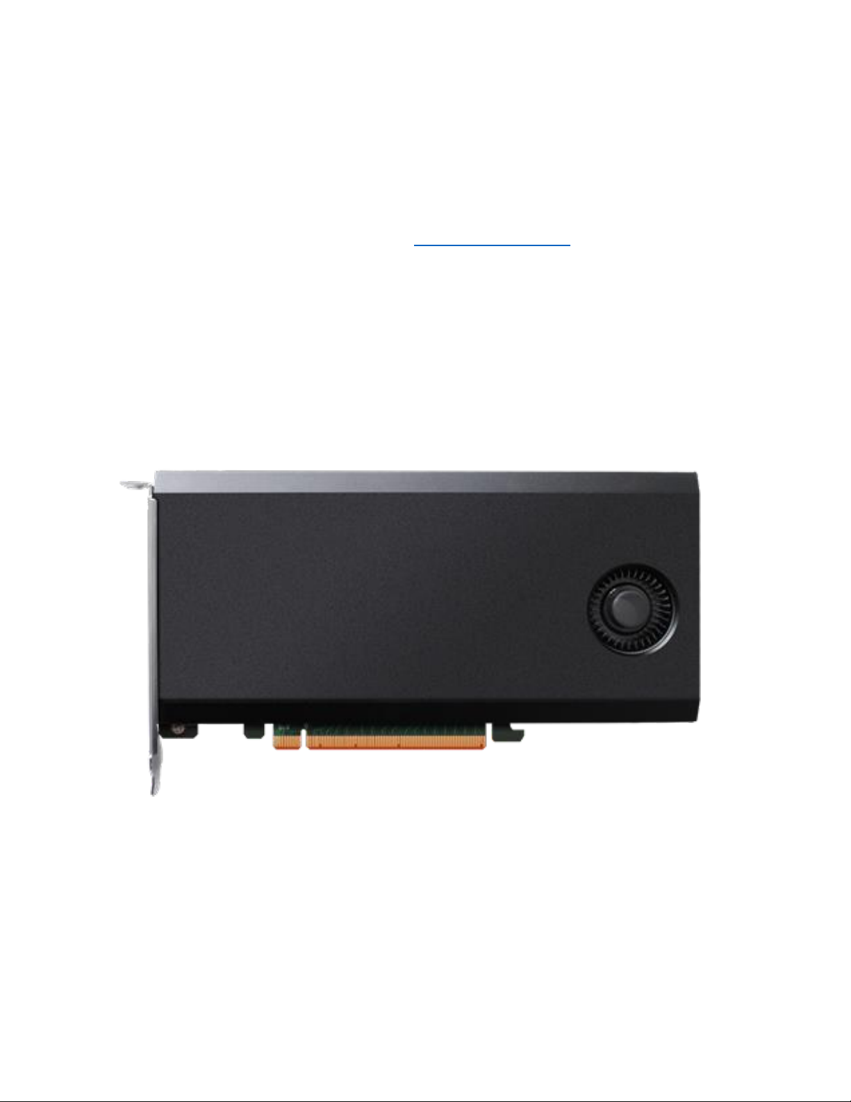
SSD7103 Hardware
Front View
3
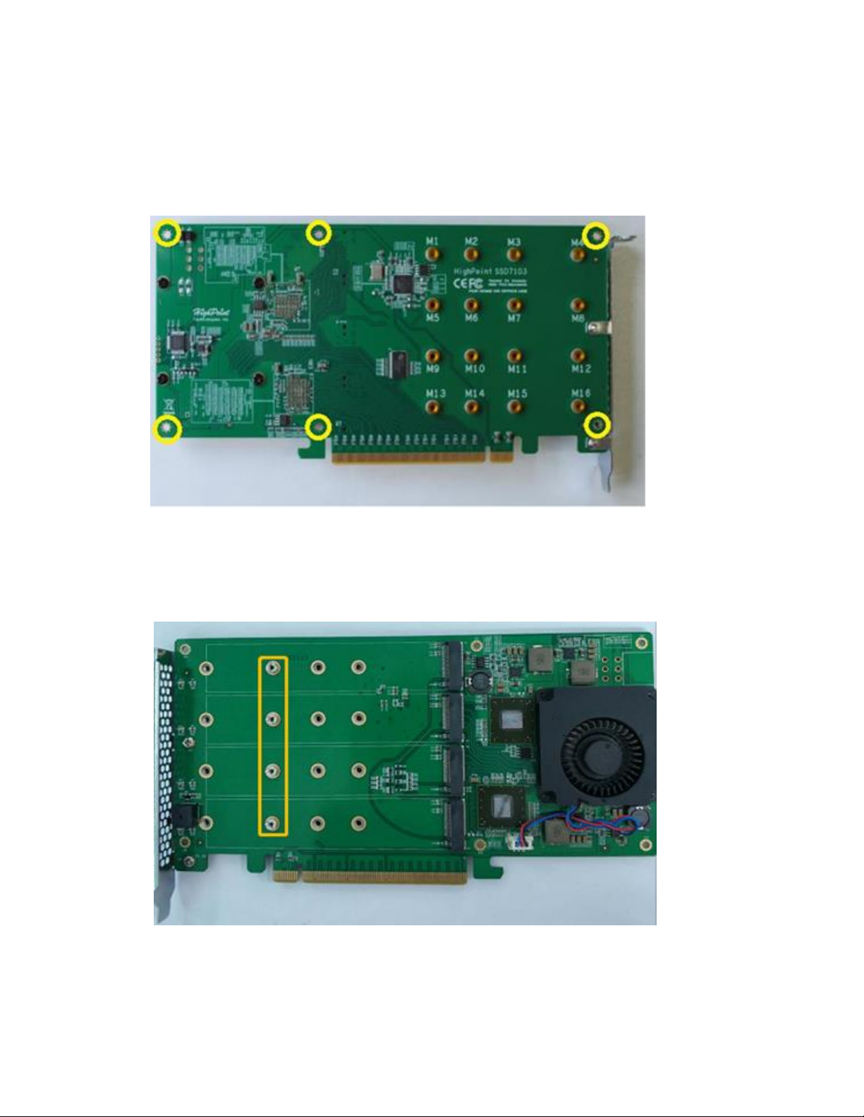
NVMe Drive Installation:
Step 1. On the rear of the SSD7103, remove the six screws that secure
the unit’s front panel to the PCB.
After removing the screws, carefully remove the front panel from the
SSD7103.
Step 2. These 4 screws are used to install the NVMe SSD’s.
4
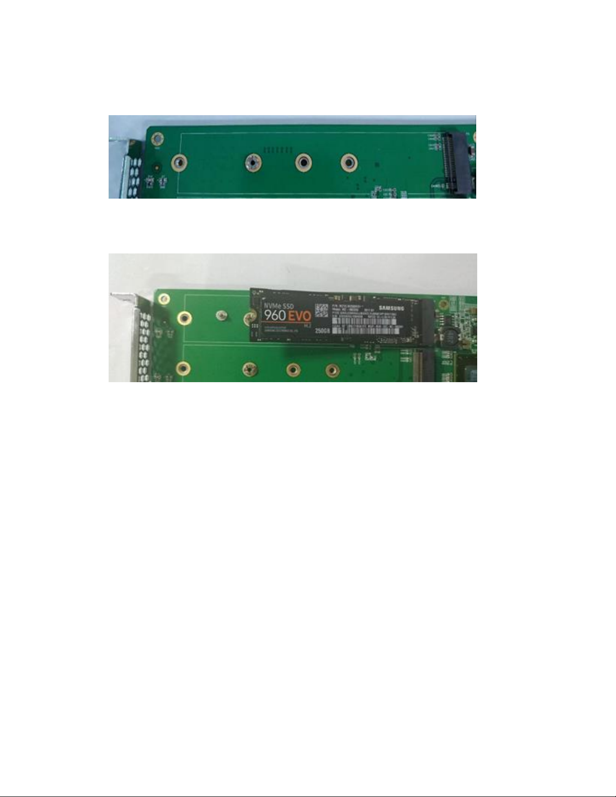
Step 3. The SSDs should be installed from top to bottom.
Remove the top screw.
Step 4. Gently insert the SSD into the slot.
5
Step 5. Refasten the screw to secure the SSD.
Repeat Steps 3 to 5 to install the remaining SSDs.
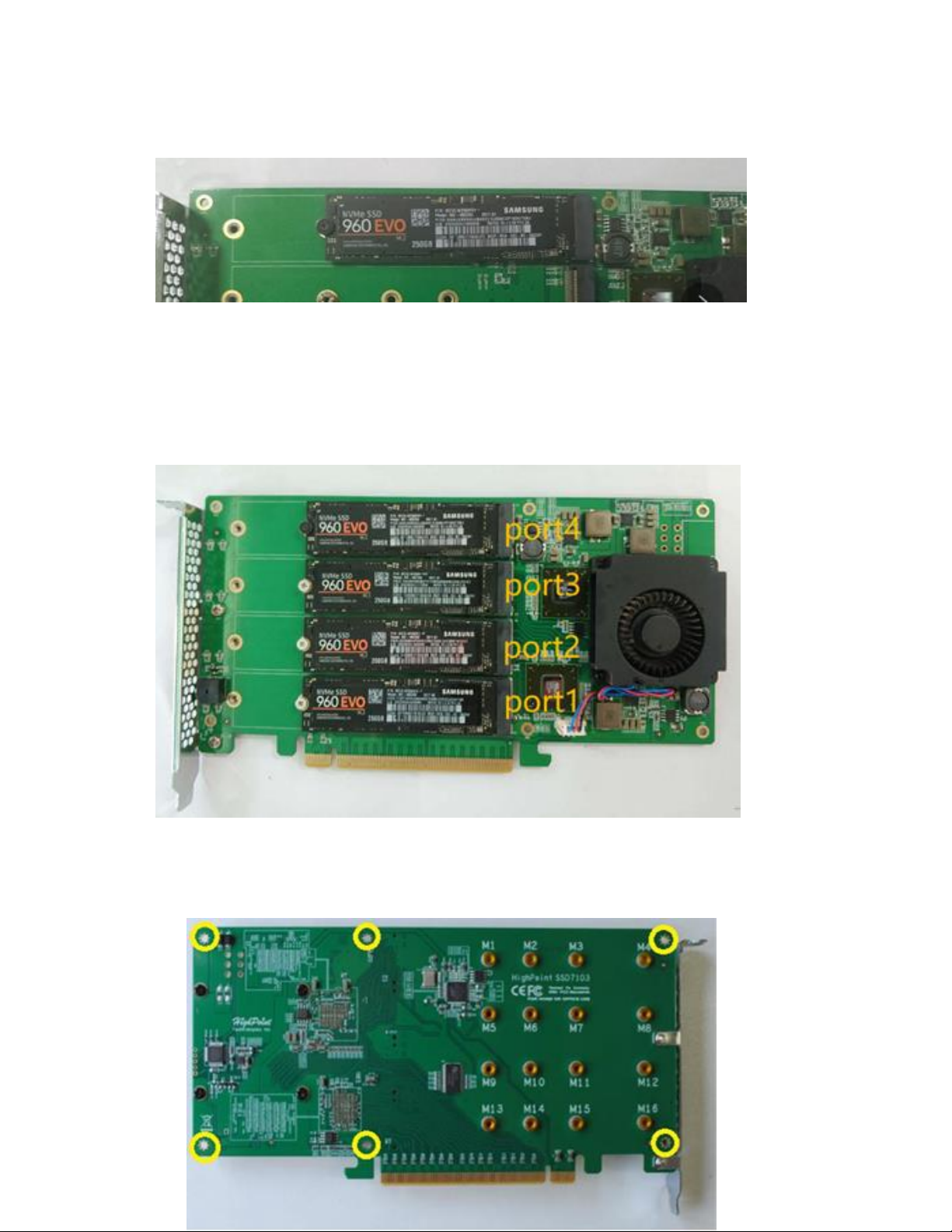
Take four Samsung SSD 960 EVO as an example. SSD7103
installs all SSDs and the connected port numbers as shown
below.
Step 6. Replace the front panel after installing all SSDs
Step 7. On the rear of the SSD7103, refasten the 6 screws that
were removed in step 1.
6

7
Bootable RAID Installation
1. Bootable RAID Windows Installation, please refer to the manual
from the HighPoint Website:
a. http://www.highpoint-
tech.com/PDF/NVMe/SSD7103/SSD7103_Windows_Installation
_Guide_v1.00_19_6_11.pdf
2. Bootable RAID Linux Installation, please refer to the manual from
the HighPoint Website:
a. http://www.highpoint-
tech.com/PDF/NVMe/SSD7103/SSD7103_Linux_Installation_G
uide_v1.00_19_6_18.pdf
Setting up the SSD7103 for a Windows operating
system
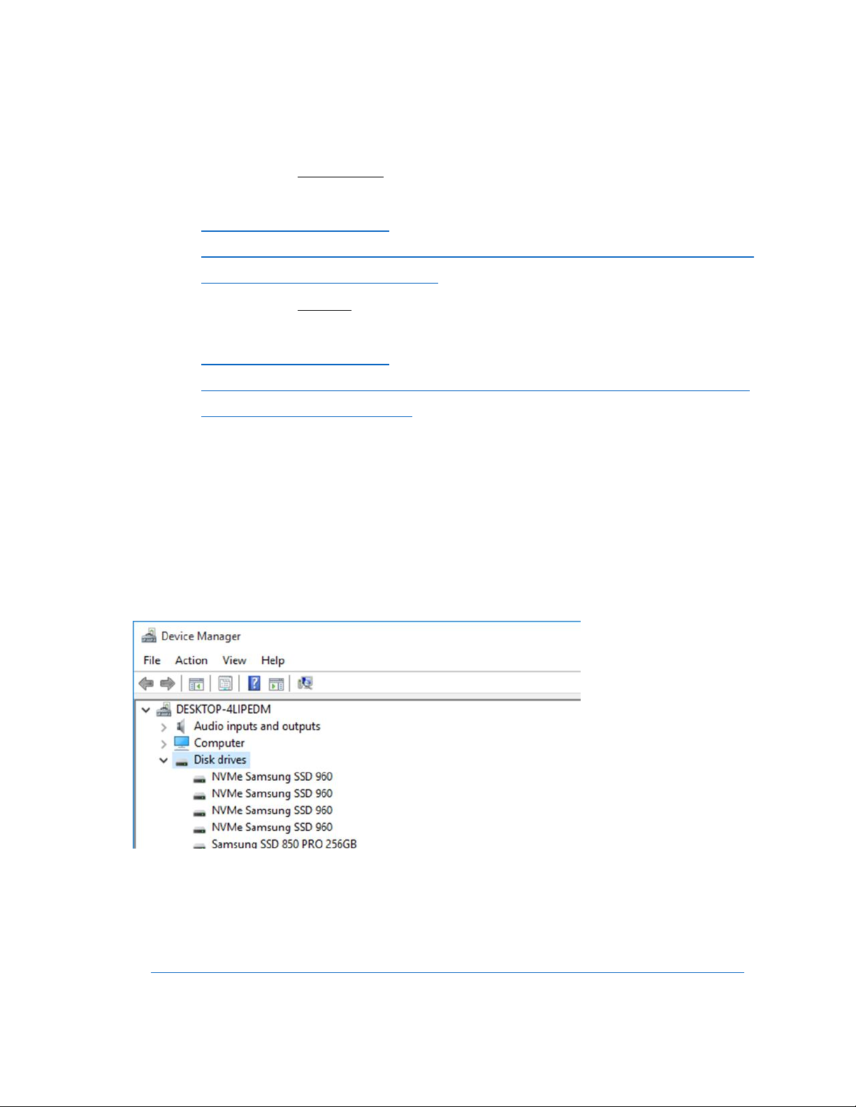
1. Verifying Installation
After booting Windows, open Device Manager, and expand
Disk drives. The installed NVMe drive should be displayed:
Take four Samsung SSD 960 EVO as an example:
2. Driver Installation
1) Download the Windows driver package from the HighPoint
website:
http://highpoint-tech.com/USA_new/series-ssd7103-download.htm
2) Once downloaded, locate the folder you downloaded the driver to.
Extract the driver package and double click the setup.exe file to
start the driver installation.
8
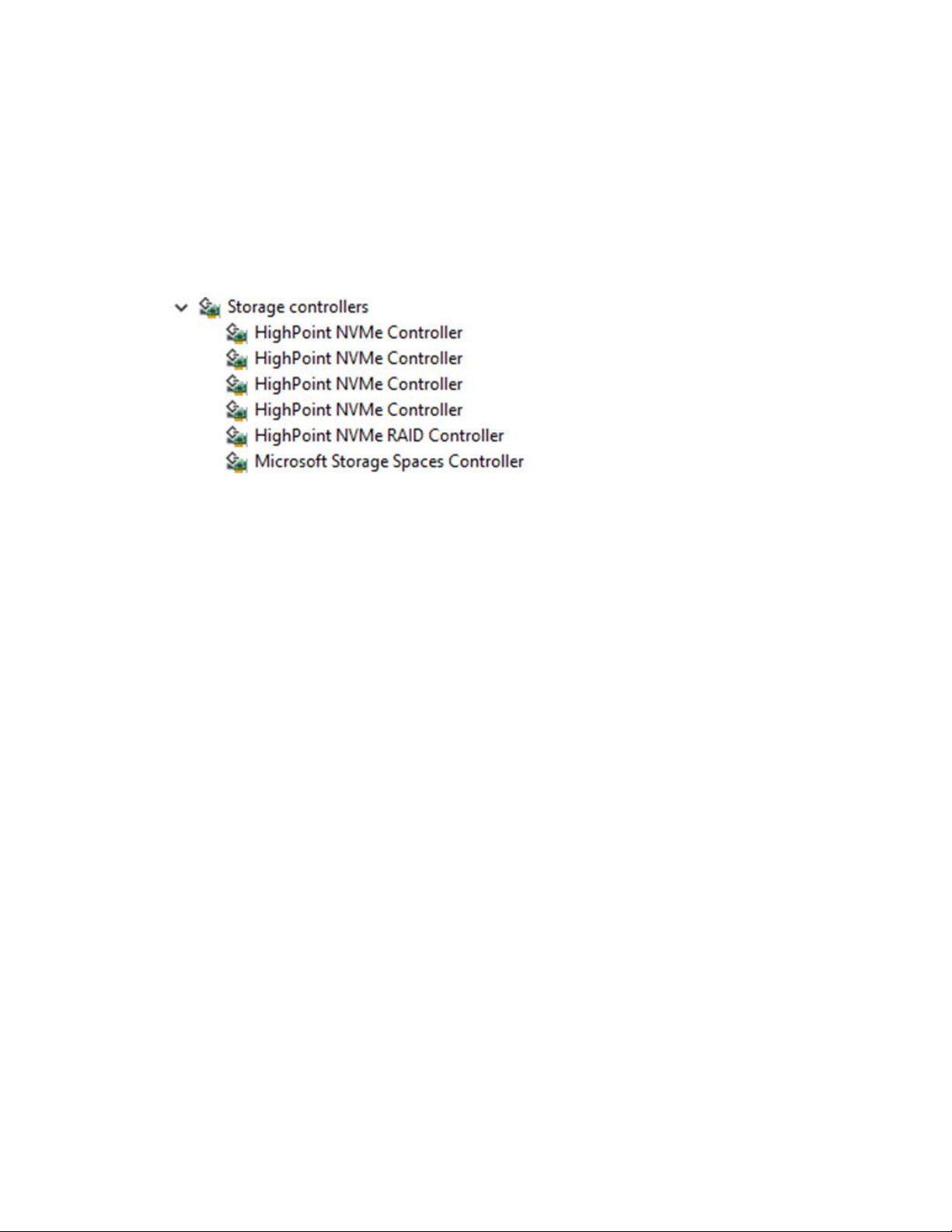
3) Follow the wizard and reboot system to complete the driver
installation.
4) Rebooting. A HighPoint NVME RAID Controller and four
HighPoint NVMe Controller entry should be displayed under
Storage Controllers:
Take four Samsung SSD 960 EVO as an example:
9
3. Installing the HighPoint RAID Management
The HighPoint RAID Management is used to configure and monitor
the SSD7103 driver. Download the HighPoint RAID Management
software package from the HighPoint website:
http://highpoint-tech.com/USA_new/series-ssd7103-download.htm
1) Extract the package and double-click the HighPoint RAID
Management program to install the software.
2) The HighPoint RAID Management will configure the SSD7103
NVMe drive automatically after installation is completed.
3) Open Windows Disk Management and check to make sure the SSD
drive is configured:
4) Create and format the partition using Disk Management and start
using the SSD7103 drive.
Using the HighPoint RAID Management
Starting the HighPoint RAID Management
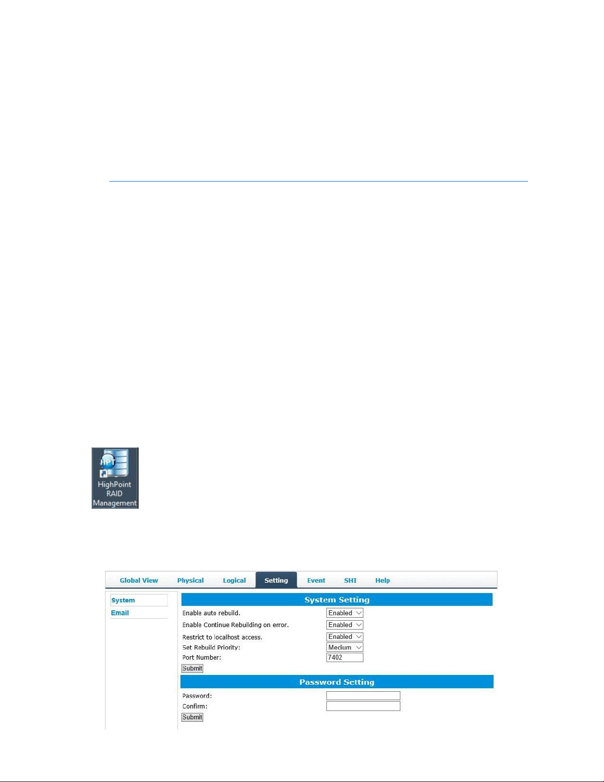
Double click the Desktop ICON to start the Web browser. It
will automatically log-in to the HighPoint RAID Management .
The password can be set after the first log-in. To change the
password, select Setting>Security from the menu bar (see page
23 for more information).
10
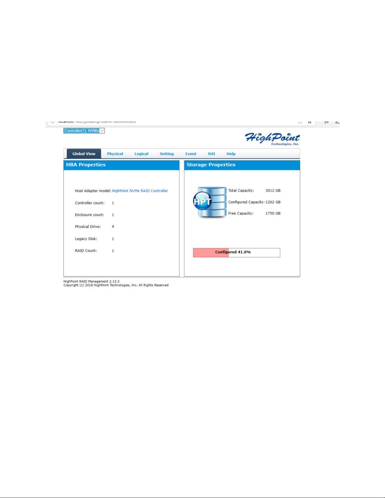
Verify the Controller Status
The Global View Tab will display the overall status of the controller.
The Virtual Disk is listed under Logical Device Information. The
individual M.2 SSDs are listed under Physical Device Information.
11
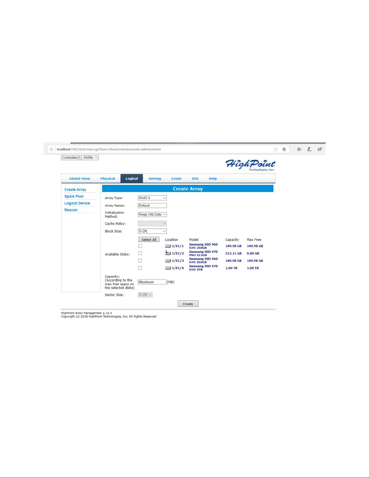
Creating an Array
To create an array:
1. Log into HRM
2. Select the proper controller from the drop down on the top left
3. Click Logical
4. Click Create Array
12

Array Type:
An array is a collection of physical disks that will be seen as one virtual
drive by your Operating System (OS).
The SSD7103 is capable of creating the following array types:
RAID 0 — Striping
RAID 1 — Mirroring
RAID 10 — Striping Mirrored array
13

Each RAID level has its pros and cons based on the application you use
it for (Note: Refer to RAID level Quick Reference)
Array Name: the name that will be displayed in Logical Device
Information (Default: RAID_<level>_<array number>)
Initialization Method: Initialization of a disk sets all data bits to 0,
essentially clearing all the data on the drive. It is important to initialize
disks as previous data physically stored on the drive may interfere with
new data.
Keep Old Data: This option skips the initialization process and
all data on each physical disk of the array will be untouched.
Quick Init: This option grants immediate access to the RAID
array by skipping the initialization process, but it will delete all
data. Note: Skipping initialization is generally not recommended
as residual data on disks may interfere with new data in the future.
Foreground: The array initialization process will be set at
high priority. During this time array is not accessible, but the
initialization process will complete much faster.
Background: The array initialization process will have a lower
priority. During this time the array will be accessible, but the
initialization process will take much longer to complete.
Note: Initializing takes a significant amount of time (approximately 2
hours per 1 TB when using hard drives).
Background and Foreground Initialization
Foreground initializing the array will completely zero out the data on the
disks, meaning the disk will be completely wiped and every bit on the
disk will be set to 0. Background initialization means the array will still
be created, and you can still write new data onto the array. But when
your array requires rebuilding, residual data left behind may interfere
with the process.
14

Cache Policy (Default: Write Back)
Write Back – Any data written to the array will be stored as cache,
resulting in better I/O performance at the risk of data failures due to
power outages. Data will be stored as cache before it is physically written
to the disk; when a power outage occurs, any data in the cache will be
lost.
Write Through – Data written to an array is directly written onto the
disk, meaning lower write performance for higher data availability.
Without cache acting as a buffer, write performance will be noticeably
slower but data loss due to power outages or other failures is significantly
minimized.
Block Size (default: 512K)
[128K to 512K are the supported block sizes]
Adjusting the block size towards your disk usage can result in some
performance gain.
In a typical RAID configuration, data of the virtual drive is striped (or
spread across) the physical drives. Having a smaller array block size will
increase the likelihood of accessing all physical drives when processing
large I/O requests. Multiple physical drives working in parallel increases
the throughput, meaning better performance.
For smaller I/O requests (512 bytes to 4 kilobytes), it is better to have
each individual disks handle their own I/O request, improving the IOPS
(I/O per second), rather than having one tiny I/O request being handled
by multiple disks.
15

Capacity (Default: Maximum)
The total amount of space you want the RAID array to take up. When
creating RAID levels, disk capacities are limited by the smallest disk.
An example of how disk capacities are limited by smallest disk.
You have 2 drives connected to the enclosure.
The first drive is 6 TB, the second is 4 TB
After creating a RAID level 1 using both drives and maximum
capacity, the first drive will have 2 TB, the second 0 TB of free
capacity
The free capacity on the second drive can be used to create a
separate array with other drives.
You may also choose how much space each array will utilize. You can
use the remaining space to create another array (up to 4 arrays are
supported).
Adding Spare Disks
Spare disks are physical disks that will immediately replace critical disks
in an array.
16

To add spare disks:
1. Log into the HRM
2. Click Logical
3. Click Spare Pool:
4. Check the box for the disk you want as a spare under Available
Disks
5. Click Add Spare, and confirm by selecting OK from the pop-up
window:
6. The disk has now been assigned as a spare. Click OK to confirm:
Disks added to the spare pool will be displayed under Spare Pool and
can be removed by checking the box before the target drive, then
17

clicking the Remove Spare button.
Physical drives marked as a spare will automatically be added to an
array whenever there is a disk failure. This feature minimizes the
chances of a data loss by reducing the time an array is in the critical
status.
Obtaining Logical Device Information
The Logical device tab is the default page after clicking the Logical tab
of the HRM. This page contains information about your RAID arrays
and the individual disks your system detects.
Logical Device Information
Arrays you create and the properties associated with them will appear
here.
Maintenance
Once an array has been created, the Maintenance menu provides options
to maintain or edit it. To access the Maintenance menu, click the
Maintenance button towards the right-hand side of the array name.
Array Information
Clicking on the maintenance button will show you the Array information
box. Different array statuses (Normal, critical, disabled) will have
different maintenance options.
18

Array Information &Maintenance Options: Normal Status
Arrays with the Normal status are healthy and functioning properly.
Arrays with the Normal status will have the following options:
Delete – deletes the selected RAID array
Verify – verifies the integrity of the RAID array
Rename – renames the RAID array.
19

Array Information & Maintenance Options: Critical Status
Arrays in the Critical status can be accessed and utilized, but are no
longer fault tolerant. A Critical array should be rebuilt as soon as
possible to restore redundancy.
A critical status array has all the normal status options except the
following:
The Array can no longer be renamed
Add Disk replaces the Verify Disk option
Once the array status changes to critical, the faulty disk will be taken
offline and you can either:
Reinsert the same disk
Insert new disk
Reinserting the same disk should trigger the rebuilding status, since data
on the disk would be recognized.
If you insert a new disk, clicking Add Disk will give you the option to
20

select that disk and add it to the array.
If a spare disk is available, an array that has entered the critical state
will begin rebuilding using the next available spare disk.
Array Information & Maintenance Options: Disabled Status
An array with the Disabled status means that the RAID level does not
have enough disks to function.
Your data will be inaccessible
Rebuilding will not trigger, since the RAID array does not
have enough parity data to rebuild.
Your options in Maintenance are:
Delete
Delete – will delete the array
21

Physical Device Information
Location — which controller and port the drive is located in
Model — model number of the drive connected
Capacity — total capacity of the drive
Max Free — total capacity that is not configured
Revision — revised version of drive
Status — Current state of drive
PCIe Width — PCIe width occupied by drivers
PCIe Speed — Rate of current bandwidth
Rescan
Clicking rescan will force the drivers to report the array status. For any
disk(s) you hot plug into the device; do not click rescan until all physical
drives are detected and appear under Logical Device Information.
22

System Setting
Using this tab, you can change the following:
Enable auto-rebuilding
Enable rebuilding on error
Restrict to localhost
Set rebuild priority
Change port number
Change HRM password
23

System Setting
Enable auto rebuild (default: Enabled)
When a physical drive fails, the controller will take the drive offline.
Once you re-insert or replace the disk, the controller will not
automatically rebuild the array unless this option is enabled.
Enable continue rebuilding on error (default: Enabled)
When enabled, the rebuilding process will ignore bad disk sectors and
continue rebuilding until completion. When the rebuild is finished, the
data may be accessible but may also be inconsistent, due to any bad
sectors that were ignored during the procedure. If this option is
enabled, HighPoint recommends checking the event log periodically
for bad sectors warnings.
Restrict to localhost access (default: Enabled)
Remote access to the controller will be restricted when enabled; other
users in your network will be unable to remotely log in to the HRM.
Rebuild Priority (default: Medium)
You can specify the amount of system resources you want to dedicate
to rebuilding the array. There are 5 levels of priority [Lowest, Low,
Medium, High, Highest]
24

Port Number (default: 7402)
The default port that the HighPoint HRM listens on is 7402. You may
change it to any open port.
Password Settings
Changing your HRM password
Under Password Setting, type your new password, confirm it, then click
Submit.
Recovering your HRM password
If you forget your password, you can delete the file hptuser.dat. Then
you need to restart the computer and open the WEBGUI to set a new
password
For Windows Users:
1. Open file explorer
2. Navigate to C:/Windows/
3. Delete hptuser.dat
4. Reboot
Email Setting
The following topics are covered under email:
SMTP Setting
Adding Recipients
25

You can instruct the controller to send an email out to the recipients of
your choosing when certain events trigger (for more information, see
Event Tab).
SMTP settings
26

To set up email alerts:
1. Check the Enable Event Notification box.
2. Enter the ISP server address name or SMTP name
3. Type in the email address of the sender (email account that is
going to send the alert)
4. Type in the account name and password of the sender
5. Type in the SMTP port (default: 25)
6. Check support SSL box if SSL is supported by your ISP (port value
will change to 465).
Note: After you click Change Setting, the password box will become
blank.
How to Add Recipients
You can add multiple email addresses as receivers of a notice.
1. Type the email of the recipient in the E-mail text box
2. Type the name of the recipient in the Name text box
3. Check which type(s) of events will trigger an email using the
respective Event Level check boxes.
4. (Optional) Click test to confirm the settings are correct by sending
out a test email
5. Click add to add the recipient to recipient list
6. The added recipient will display in under Recipients
27

The email will include the output recorded in the event log.
Example email message:
Figure 1. Example event log email
Event Tab
In the event tab, you can see log entries associated with the HighPoint
device. The event log provides useful information when troubleshooting
your set up.
In the event tab, there are four options available:
Download – Save the log file on your computer
Clear – Clears all log entries
Prev – View previous log page
Next – View next log page
SHI (Storage Health Inspector)
S.M.A.R.T Attributes
Schedule a task(Task list and Health Inspector Scheduler)
SHI outputs information collected using SMART (Self-Monitoring
Analysis and Reporting Technology) Hard Drive Technology. The data
provided on this tab helps you to anticipate any disk failures based on a
variety of monitored hard disk properties.
28

How to Enable SMART Monitoring
To access SMART attributes of an individual disk:
1. Log in to the HRM
2. Select the proper controller using the drop down menu on the top left
3. Click the SHI tab
4. Click Detail on the desired disk
The TBW (Total Bytes Written) information can be used to monitor the
lifespan of the NVMe drives.
29

How to Use the Health Inspector Scheduler
The Health Inspector Scheduler (HIS) enables you to schedule
disk/array checkups to ensure disks/array are functioning optimally.
30

How to Create a New Verify Task
All Redundant RAIDs will appear under New Verify Task
1. Log into the HRM
2. Select the proper controller from the top left drop down
3. Click SHI
4. Click Schedule
5. Select the array you want to schedule the verify task
6. Type the name in Task Name entry box
7. Choose whether you want to schedule
8. One time verify task on specific date (YYYY-MM-DD)
at (HH:MM:SS, 24-hr clock)
9. Or a specific schedule you can adjust based on Daily, Weekly,
or Monthly options
10. Click Submit
11. Your entry will appear under Tasks List
Note: New Verify Task box only appears if you have normal status
arrays. If you have a critical array, New Rebuild Task will replace New
Verify Task.
31

Troubleshooting
This section provides guidelines to some problems you may encounter:
Handling Critical Arrays
Handling Disabled Arrays
PC hangs when card is installed.
32

Handling Critical Arrays
Bad sector is detected on a disk
Common scenarios for
that is part of an array
critical status
Unrecoverable data during
rebuilding
Defective port or cable
interrupts rebuilding process
When your disk status turns critical, your array as a whole is still
accessible, but one or more disks is faulty (depending on your RAID
level), and the array is in danger of failing.
To recover from this situation,
1. Backup your existing data.
2. Identify which disk is faulty.
You can refer to the LED lights on the enclosure
Refer to the HRM Logical tab and Event tab.
3. Re-insert the faulty disk or replace with a new disk.
The array will rebuild automatically if your auto-rebuild setting is
enabled and you reseated the faulty disk.
Note: Click Rescan if the array still does not rebuild automatically.
4. If the new disk is added and it does not automatically start
rebuilding, you can manually add the disk in maintenance.
Log into the HRM
Click Logical Tab
33

Click Maintenance>Add Disk> select the appropriate disk
5. Rebuild should now start.
If rebuild does not start, click ‘Rescan’ on the left hand panel.
Note: Rebuilding an array takes on average 2 hours per 1 Terabyte of
disk capacity. The process will scan through the entire disk, even if you
have very little used disk space.
Rebuilding Stops Due to Bad Sectors
If rebuilding fails to complete due to bad disk sector errors (check in the
Event Log), there is an option to continue rebuilding on error in the
HighPoint HRM.
1. Log into the HRM
2. Click Setting tab
3. Under System Setting, change Enable Continue Rebuilding on
Error to Enabled
This option will enable rebuilding to ignore bad sectors and attempt to
make your data accessible. It is important to backup immediately after
backup is complete and replace or repair the disks with bad sectors.
Critical array becomes disabled when you removed faulty disk
If this is the case, you may have removed the wrong disk. When you
remove the wrong disk from a critical array, the array status may
become disabled. Data is inaccessible for disabled arrays. Follow these
steps to restore the array to the previous state.
1. Shut down your PC
34

2. Place all disks back to original configuration
3. Boot up PC
Your array should be back to Critical status. Identify the correct disk and
rebuild from there.
Handling Disabled Arrays
If two or more disks in your array go offline due to an error or physical
disconnection your array will become disabled.
Disabled arrays are difficult to recover, so it is important to fix any
critical status as soon as possible
35

Online Array Roaming
One of the features of all HighPoint RAID controllers is online array
roaming. Information about the RAID configuration is stored on the
physical drives. So if a card fails or you wish to switch cards, the RAID
configuration data can still be read by another HighPoint card.
36

Help
Online Help
Register Product
Online Help redirects you to additional documentation concerning the
HighPoint HRM.
Register Product takes you to the HighPoint Online Web Support
Portal. On this page you can create a new customer profile where you can
register your product, or post an online support ticket.
37

Table 1.HRM Icon Guide
Critical – missing disk
A disk is missing from the array bringing it to ‘critical’ status.
The array is still accessible but another disk failure could result
in data loss.
Verifying
The array is currently running a disk integrity check.
Rebuilding
The array is currently rebuilding meaning you replaced a failed
disk or added a new disk to a ‘critical’ state array.
Critical – rebuild required
The array has all disks, but one disk requires rebuilding.
Disabled
The icon represents a disabled array, meaning more than one
disk failed and the array is no longer accessible
Initializing
The array is initializing. The two types of initialization are
Foreground and Background. (See Initialization)
Uninitialized
The array initialization process has been interrupted, and the
process is incomplete.
Not Initialized
Disk is not initialized yet, and needs to be initialized before use
OCE/ORLM
Array is performing a OCE/ORLM operation
OCE/ORLM has stopped
The array expansion process has been stopped.
Legacy
An existing file system has been detected on the disk. These
disks are classified as legacy drives.
38

Spare
The device is a spare drive, it will automatically replace any
failed drive part of an array.
Normal
The array status is normal
Initializing
The array is initializing, either foreground or background
initialization
Initialization Stopped
The initialization has been stopped. Current status is
uninitialized.
Critical – Inconsistency
Data in the array is inconsistent and needs to be rebuilt.
Critical – missing disk
A disk has been removed or experienced failure, and user
needs to reinsert disk or add a new disk.
Rebuilding
The array is currently rebuilding.
Verifying
The array is performing a data consistency check. Array status
will show ‘verifying’.
Disabled
The array does not have enough disks to maintain the RAID
level. A disabled array is not accessible.
OCE/ORLM
Array is expanding its capacity or migrating to a different raid
39

level. Status will display ‘Expanding/Migrating’
The ‘Expansion/Migrating’ process has been stopped. The
OCE/ORLM stopped
status will display ‘Need Expanding/Migrating’
Critical – OCE/ORLM
A disk member is lost during the OCE/ORLM process.
Critical – OCE/ORLM - rebuild
The expanding/migrating array requires a rebuild.
40

Type
Description
Min.
Usable
Advantage
Disadvantage
Application
disks
space
JBOD
Just a bunch
1
100%
Each drive can be accessed as a
No fault tolerance - failure of one
Backup
of disk
single volume
drive results in complete data loss
Disk Striping
Offers the highest performance
No fault tolerance - failure of one
Temporary file,
RAID 0 2 100%
drive results in complete data loss
performance driven
application.
Disk
Provides convenient low-cost
Useable storage space is 50% of
Operating system,
RAID 1
Mirroring
2
50%
data redundancy for smaller
total available capacity. Can
backup, and transaction
systems and servers
handle 1 disk failure.
database.
Disk
High read performance and
Useable storage capacity equals
Fast database and
RAID 10
Mirroring
4
50%
medium write performance
total capacity of all drives in the
application servers which
followed by
with data protection for up to
array minus two
need performance and
stripe
2-drive failures
data protection
High read performance, and
Not recommended for database
Data archives, and ideal
Disk Striping
medium write performance
applications that require
for application that
RAID 5
with Rotating
3
67-87%
with data protection with a
frequent/heavy write sessions.
require data protection
parity
single drive failure
Can handle 1 disk failure.
Disk
High read performance,
and
Not recommended for
Data archives and ideal
RAID 50
Mirroring
6
67-75%
medium write performance
applications that require
for application that
followed by
with data protection in case of
frequent/heavy write sessions.
requires data protection
RAID5
up to two drives failure
High read performance,
and
Not recommended for
Data archives and ideal
Disk Striping
medium write performance
applications that require
for application that
RAID 6
with dual
4
50-75%
with data protection in case of
frequent/heavy write sessions.
requires data protection
rotating
up to two drives failure
parity
Table 2. RAID Level Reference Guide
41

HighPoint Recommended List of Hard Drives
HighPoint maintains a list of tested hard drives and SSD suitable for
RAID applications. Since not every drive in the market can be tested,
this list is meant to be a general guideline for selecting hard drives and
SSD operating in a RAID environment. Regular, desktop grade drives
are highly not recommended for RAID use.
http://highpointtech.com/PDF/Compatibility_List/SSD7103_Compatibility_List_062
619.pdf
Contacting Technical Support
For any help and support, submit a support ticket online
at http://www.highpoint-tech.com/websupport/ .
Please also check our Support page for articles that may
answer your questions.
http://highpoint-tech.com/USA_new/support.htm
42
 Loading...