

Page 1
1
RocketStor 5315
Quick Installation Guide
V1.0
Jan. 4, 2013
Page 2

2
Table of Contents
HighPoint RocketStor 5315 .......................................................... 3
Kit Contents ................................................................................. 3
RocketStor 5315 Hardware ......................................................... 4
Configuring and using the RocketStor 5315 ................................ 6
Customer Support ....................................................................... 7
FCC Part 15 Class B Radio Frequency Interference Statement .... 8
Page 3

3
HighPoint RocketStor 5315
Industry's First 6Gb/s Port Multiplier Storage Dock
The RocketStor 5315, the industry’s first 6Gb/s Port Multiplier storage dock,
delivers cost-effective external mass-storage solutions, and is fully compatible
with PC and Mac platforms.
The 6Gb/s SATA Port Multiplier architecture delivers twice the performance of
conventional SATA Port Multiplier enclosures, and supports up to five 6Gb/s
SATA hard drives though a single eSATA connection. The RocketStor 5315
supports RAID Storage configurations ready when connected to HighPoint
RocketRAID 600 eSATA HBA’s.
Kit Contents
RocketStor 5315 Storage Docking device
One 1M eSATA cable
Quick Installation Guide
Power adapter (Including the AC Power cord: CCC, EUR and US)
Page 4
4
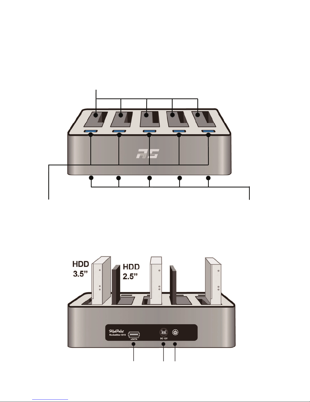
RocketStor 5315 Hardware
Front View
Back View
5 x 2.5” / 3.5” SATA Slots
Individual Power Button/
Active / Fail LEDs
6Gb/s eSATA Port
DC-In Power Button
Power LEDs
Page 5
5
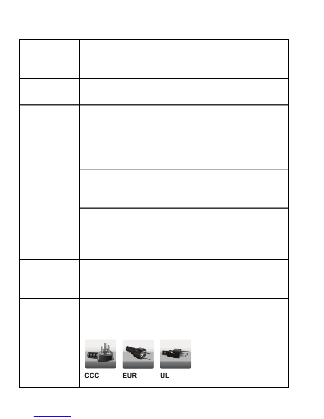
5 x 2.5” / 3.5”
SATA Slots
The RocketStor 5315 supports 5 disk configurations of
2.5” and 3.5” SATA hard drives of any performance level
and capacity.
Power LEDs
When powered on, the RocketStor 5315 will emit blue
light from the base of the enclosure.
Individual
Power
Button/
Active / Fail
LEDs
Individual Power Button:
Each bay has a dedicated, dual-function Power
Button/LED indicator. The power button allows you to
safely add or remove drives from the each bay, as
needed.
Individual Active LEDs:
The LED will glow blue when the bay is powered on. The
LED will flash when the drive is being accessed.
Individual Fail LEDs:
When the RocketStor 5315 is paired with a RocketRAID
600 HBA, the LED will turn Red if disk is no longer
functioning properly or fails.
6Gb/s eSATA
Port
Use the 6Gb/s eSATA port to connect the RocketStor 5315
to the motherboard’s Port Multiplier capable eSATA port,
or an eSATA PCIe controller card.
DC-In
Power Adapter jack: Connect the AC Power cord to the
Power Adapter and connect the AC Power plug to the
Power pack.
CCC is for Asia
EUR is for Europe
UL is for the United States
Page 6

6
Power Button
The RocketStor 5315’s main power button. Press to
power on the unit. Press and hold to power it off (the
blue LED will turn off when the unit is fully powered
down).
Configuring and Using the RocketStor 5315
Using the RocketStor 5315 by step
1. To install a drive: Carefully align the SATA device’s gold fingers with the bay’s
SATA connector. Gently push the device straight down until secure.
2. Connect the RocketStor to the RR600 series HBA using an eSATA cable.
3. Connect the power adapter to the DC-In port (back of the RocketStor).
4. Press the power button on the rear of the RocketStor 5315. The bottom
panel of the storage dock will emit blue light when fully powered on.
5. Each SATA bay LED will glow blue when a drive is installed and powered on.
6. The temperature and SMART attributes of each drive are displayed under
“SHI” of the HighPoint RAID Management interface (WebGUI).
7. Before removing a drive, first use the “unplug” function of the
Management interface, then power off the drive using the corresponding
Power/LED button.
Note: The surface temperature of some 3.5" hard disks may exceed 50
degrees C after extended use - approach with caution. Carefully assess the
surface temperature of any hard disk before removal. If you suspect the
temperature is too high, please power down the target drive using the
bay's independent power button. Allow the drive to cool for several
minutes before removal.
Page 7
7
8. Hold the RocketStor 5315’s power button down to power off the storage
dock.
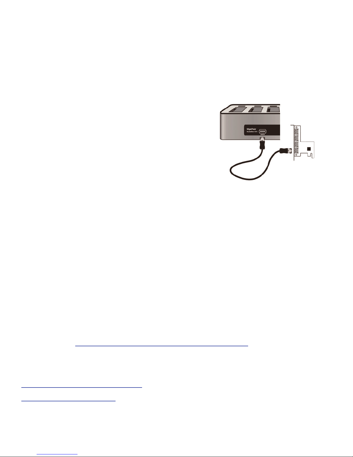
Connecting eSATA cables
The RocketStor 5315 utilizes industry standard
eSATA ports and cables. The rear panel of the
Storage Dock provides one eSATA ports that can
be connected to PCIe eSATA host adapter cards,
such as RocketRAID 600 series HBA’s.
Optional RAID Storage Setup
Please refer to the RR642/RR644L product webpage (Resources) for more
information.
Customer Support
If you encounter any problem while utilizing the RocketStor 5315, or have any
questions about this or any other HighPoint Technologies, Inc. product, feel free
to contact our Customer Support Department.
Web Support: http://www.highpoint-tech.com/websupport/
HighPoint Technologies, Inc. websites:
http://www.highpoint-tech.com
http://www.hptmac.com
Page 8

8
FCC Part 15 Class B Radio Frequency Interference
Statement
This equipment has been tested and found to comply with the limits for a Class
B digital device, pursuant to part 15 of the FCC Rules. These limits are designed
to provide reasonable protection against harmful interference in a residential
installation. This equipment generates uses and can radiate radio frequency
energy and, if not installed and used in accordance with the instructions, may
cause harmful interference to radio communications. However, there is no
guarantee that interference will not occur in a particular installation. If this
equipment does cause harmful interference to radio or television reception,
which can be determined by turning the equipment off and on, the user is
encouraged to try to correct the interference by one or more of the following
measures:
Reorient or relocate the receiving antenna.
Increase the separation between the equipment and receiver.
Connect the equipment into an outlet on a circuit different from that to
which the receiver is connected.
Consult the dealer or an experienced radio/TV technician for help.
Modifications not expressly approved by the manufacturer could void the user’s
authority to operate the equipment under FCC rules.
This device complies with part 15 of the FCC Rules. Operation is subject to the
following two conditions: (1) this device may not cause harmful interference,
and (2) this device must accept any interference received, including
interference that may cause undesired operation.
European Union Compliance Statement
This Information Technologies Equipment has been tested and found to comply
with the following European directives:
European Standard EN55022 (1998) Class B
European Standard EN55024 (1998)
© Copyright 2013 HighPoint Technologies, Inc. All right reserved.
 Loading...