

Page 1
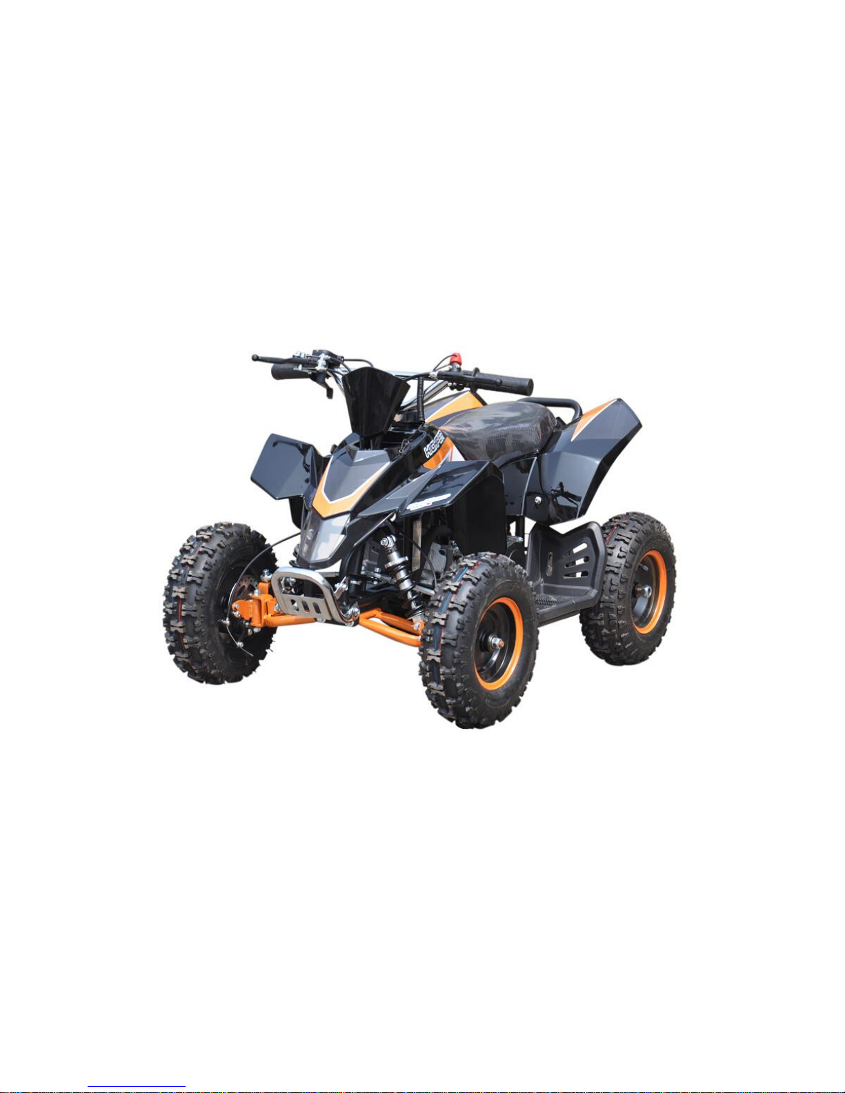
49CC MINI ATV
OWNERS MANUAL
Read this entire manual before using
Page 2

1
INSTRODUCTION
Thank you for purchasing this mini ATV. The proper care and maintenance that your vehicle
requires is outlined in this manual. Following the instruction will ensure a long trouble-free
operating life of this vehicle and your satisfaction with it.
The owner’s manual corresponded to the latest state of this vehicle at the time of printing.
Slight deviations resulting from continuing development and design can, however, not be
completely excluded. All specifications are non-binding, we reserve the right to modify or
delete technical specification, parts, design, etc… without prior notice.
SAFETY WARNING
SAFETY WARNINGS
This vehicle is NOT A TOY and ONLY used in closed off areas remote from public road traffic.
Never permit children under age 12 to operate this ATV.
Adult’s supervision is required if children under age 16.
WARNING:
Riding a mini ATV can be a hazardous activity. Certain conditions may cause the equipment to
fail without fault of the manufacturer. Like other electric vehicles, the Mini ATV can and is
intended to move, and it is therefore possible to lose control, fall off and/or get into dangerous
situations that no amount of care, instruction or expertise can eliminate. If such things occur
you can be seriously injured or die, even when using safety equipment and other precautions.
RIDE AT YOUR OWN RISK AND USE COMMON SENSE.
This manual contains many warnings and cautions concerning the consequences of failing to
maintain, inspect or properly use your mini ATV. Because any incident can result in serious
injury or even death, we do not repeat the warning of possible serious injury or death each
time such a possibility is mentioned.
APPROPRIATE RIDER USE AND PARENTAL SUPERVISION
This manual contains important safety information and use tips to help you and your child
operate and handle the mini ATV. Carefully read the manual entirely together with your child
before letting your child ride it for first time. The manual also contains important information on
servicing the vehicle.
It is your responsibility to review the manual and make sure that all riders understand all
warnings, cautions, instructions and safety topics and assure that the riders are able to safely
and responsibly use this product and protect your child from injury. We recommend that you
periodically review and reinforce the information in this manual with your child, and that you
inspect and maintain your children’s vehicle to insure their safety. The recommended rider
age of 12 years is only an estimate, and can be affected by the rider’s size, weight or skills.
Any rider unable to fit comfortably on the mini ATV should not attempt to ride it.
It is important and necessary to conduct the technical training for your child before first
use. To get the train information, please contact the dealer who you purchase the
vehicle from. Before your child complete the training, do not let your child use this
vehicle.
Children often underestimate or fail to recognize the dangerous situation, you should make it
clear to your child that should not, under any circumstances, operate the vehicle without
supervision and that your child may only drive at speed that are commensurate with the child’s
riding ability and other road condition.
A parent’s decision to allow his or her child to ride this product should be based on the
Page 3

2
child’s maturity, skill and ability to follow rules.
Keep this product away from small children younger than age 12 and remember that this
product is intended for use only by persons who are, at a minimum, completely comfortable
and competent while operating the vehicle
ACCEPTABLE RIDING PRACTICES AND CONDITIONS
Always check and obey any local laws or regulations which may affect the locations
where the Mini ATV may be used.
PROHIBIED ITEMS
★ Do not touch the brakes or engine when the ATV is in use as they can become very hot.
★ This vehicle should use mixture of the unleaded gasoline and the two cycle engine oil. The
volume ratio is 25:1. Do not use any degraded fuel (which smells sour) or fuel of wrong
mixture ratio. It will cause a poor start, insufficient output r damage the engine.
★ Do not use 4 cycle engine oil. (Otherwise, it causes the plug to be degraded, the piston ring
to seize or the muffler to be clogged)
★ Do not run the engine in a room or poor ventilated area. (The exhaust gas includes
odorless but hazardous carbon monoxide.)
★ Do not put your fingers and other body parts near to the drive chain, steering system,
wheels and all other moving components.
★ Do not, spill or use any gasoline near afire, stove, oven, boiler or other instruments which
uses a pilot light or spark. (Otherwise, it may cause an explosion.)
★ Smoking is strictly prohibited while refilling the fuel
★ While the engine is running or while it remains hot soon after stopping, do not remove the
lid of the fuel tank or refill the fuel. (Before refilling the fuel, stop the engine and cool it down 2
minutes or more.)
★ If any gasoline is spilt or smelled or any danger of explosion felt, do not run the engine.
★ Do not ride at night or when visibility is limited.
★ Never carry passengers or allow more than one person at a time to ride the mini ATV
★ Do not check any spark while keeping the spark plug removed.
★ Do not run the engine with the muffler or air cleaner cover removed.
★ Do not touch any hot muffler or engine part. (Otherwise, it may cause a burn.)
★ When the engine runs, do not touch any spark plug cap or high tension cord. (Otherwise, it
may cause an electric shock and harm you body.)
★ Never hitch a ride with another vehicle.
★ Do not ride in raining, snowing day, slippery surface, or unstable due to gravel, sand etc.
★ Never use alcohol or drugs before or while operating.
★ Do not ride if you weight over 155lbs/70KG.
★ You insurance policy may not provide coverage for accidents involving the use of this
vehicle. Consult your insurance agent before using this vehicle.
PROPER RIDING ATTIRE
Always wear proper protective equipment such as an approved safety helmet, elbow pads and
kneepads. A helmet may be legally required by local law or regulation in your area. A
long-sleeved shirt, long pants and gloves are recommended. Always wear athletic shoes,
never drive barefooted or in sandals, and keep shoelaces tied and out of the way of the wheels,
motor and drive system.
FAIL TO USE COMMON SENSE AND HEED THE ABOVE WARNINGS INCREASES RISK
Page 4

3
OF SERIOUS INJURY. USE WITH APPROPRIATE CAUTION AND SERIOUS ATTENTION
TO SAFE OPERATION.
SAFETY REMINDERS
PRE-RIDE CHECKLIST
Loose Parts
Check and secure all fasteners before every ride. Make sure steering stem clamp bolts are
locked properly in place. There should not be any unusual rattles or sounds from loose parts or
broken components. If you are not sure, ask an experienced mechanic to check.
Brake
Check the brake for proper function. When you squeeze the lever, the brake should provide
positive braking action.
Frame, Fork and Handlebars
Check for cracks or broken connections. Although broken frames are rare, it is possible for an
aggressive driver to bash into a curb or wall and wreck and bend or break a frame. Get in the
habit of inspecting yours regularly.
Tire Inflation
Periodically inspect the tires for excess wear, and regularly check the tire pressure and
re-inflate as necessary. If you get a flat tire, the inner tube can be patched or a new tube can
be purchased from an authorized repair shop.
Safety Gear
Always wear proper protective equipment such as an approved safety helmet, elbow pads and
kneepads. Always wear shoes (lace-up shoes with rubber soles), never drive barefooted or in
sandals, and keep shoelaces tied and out of the way of the wheels, motor and drive system
ATTENTION
We recommend checking all tightenings after the first time use. Special attention should be
paid to the following parts:
■ Footrest
■ Engine sprockets (Racing version only)
■ Shock absorber
■ Engine bolts and nuts
■ Rear sprocket
ECOLOGIC DRIVE
The noise and the pollution of every vehicle depend on how it is driven.
We strongly recommend you to drive steadily, without strong acceleration and deceleration
During off road use, do not damage the environment, avoid noise and everything that can
disturb persons and animals.
Use a sport drive only on race circuits.
Page 5

4
HAND DRIVE CONTROLS
1. Rear brake lever
2. Front brake lever
3. Stop switch
4. Emergency kill switch
5. Accelerator lever
Page 6
5
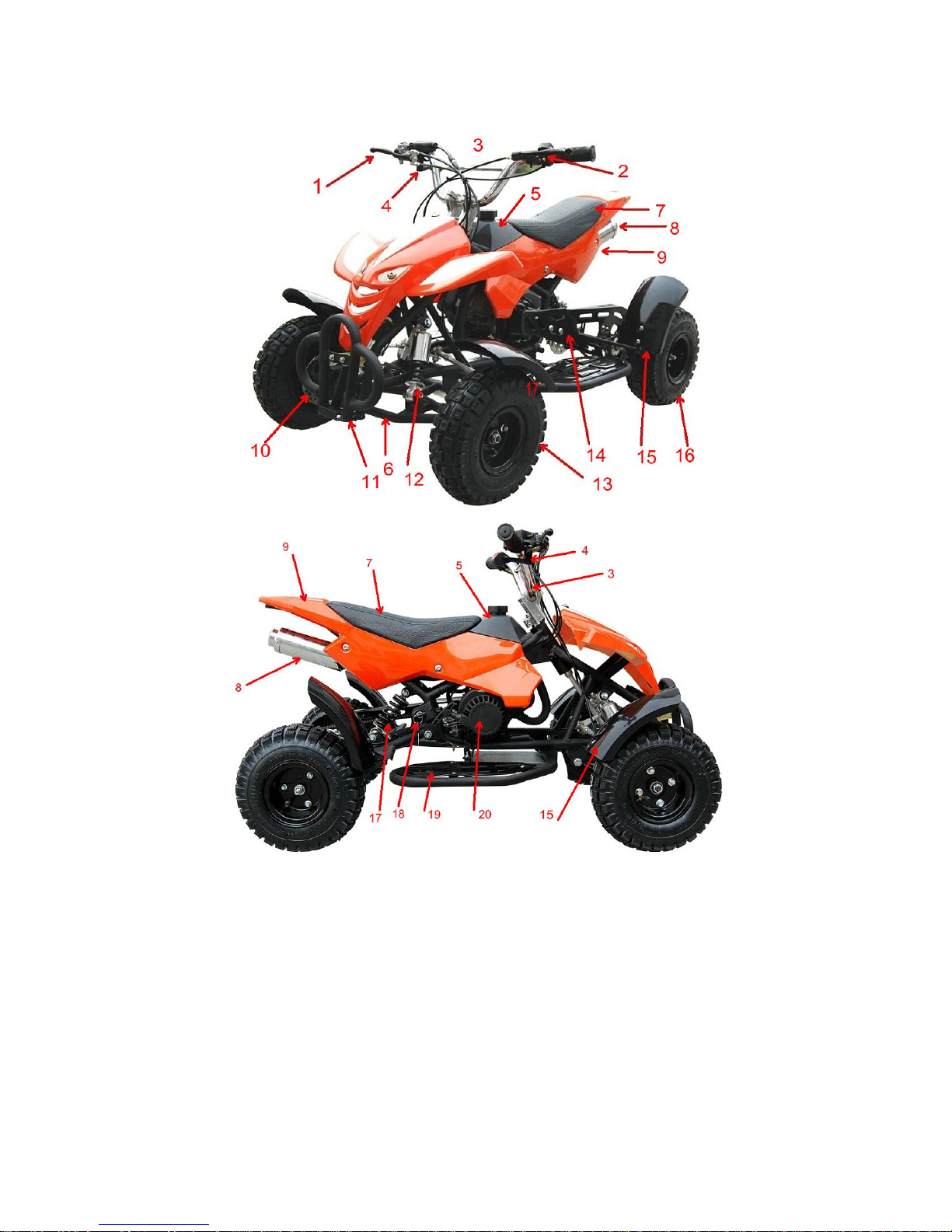
PRODUCT DESCRIPTION
1. front brake lever
2. rear brake lever
3. handlebar
4. throttle
5. tank
6. front swing arm
7. seat
8. muffler
9. plastic body
10. front disk brake
11. bumper
12. front shock
13. front tire 4”
14. chain cover
15. wheel fender
16. rear tire 4”
17. rear shock
18. ignition key
19. footrest
20. engine
Page 7
6
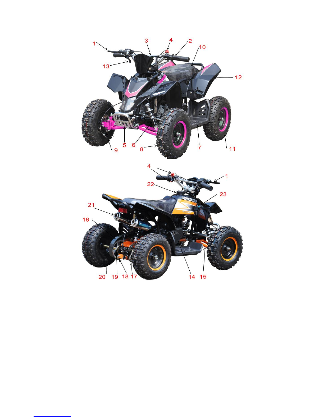
1. front brake lever
2. rear brake lever
3. handlebar
4. kill switch
5. bumper
6. front shocker
7. footrest
8. front tire(4.10-6)
9. front disk brake
10. seat
11. rear tire(13*5-6)
12. plastic body
13. throttle
14. engine
15. front swing arm
16. chain cover
17. rear disk brake
18. chain
19. rear sprocket
20. rear axle
21. muffler
22. tank cap
23. ignition key
Page 8
7
BEFORE YOU BEGIN
Remove contents from box. Remove the foam separators that protect the components from
damage during shipping. Inspect the contents of the box for scratches in the paint, dents or
kinked cables that may occurr during shipping. Because the product was 85 percent
assembled and packed at the factory, there should not be any problems, even if the box has a
few scars or dents.
Estimated Assembly and Set-Up Time
We recommend assembly by an adult with experience in motorbike or bicycle mechanics.
Allow up to 30-40 minutes for assembly.
Required Tools
Some tools may be supplied; however, we recommend the use of mechanic’s grade tools. Use
the supplied tools only as a last resort.
The list of tool required is as follows
·Open end wrench 10mm / 13mm/ 17mm / 22mm
·Allen wrench 5mm / 6mm/ 8mm
·Bicycle style tire pump with pressure gauge
Assembly illustration and instruction
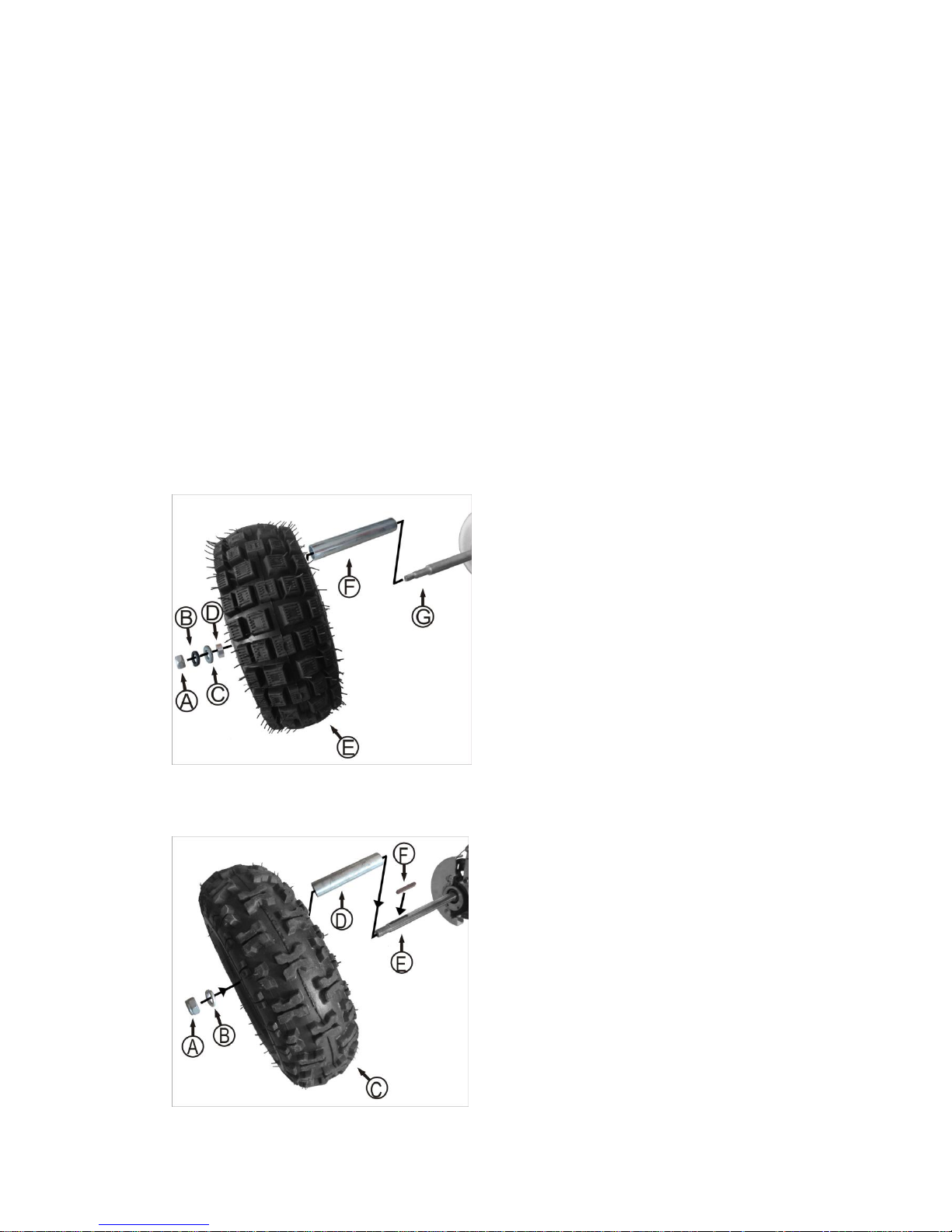
ASSEMBLY REAR WHEEL 4”
A: Nut M10 2PCS
B: Spring Washer Φ10 2PCS
C: Washer Φ10 2PCS
D: Bush Φ22×1.8×139 1pcs (Left)
Φ22×1.8×139 1pcs(Right)
E:Rear wheel 2PCS
F:Sleeve Φ22×1.8×10 2PCS
G:Rear axle
1.Install the sleeve(F) to the rear axle (G).
2.Fix the rear wheel (E) through the axle (G).
3.Mount the bush(D),flat washer(C),spring
washer (B) and nut(A) in sequence, then
tighten the nut securely with 17mm open end
wrench.
ASSEMLY REAR WHEEL 6”
A: Nut M14 2pcs
B: Washer Φ14 2pcs
C: Rear wheel
D: Sleeve Φ22×1.8×112 2pcs
E: Rear axle
F: Pin 2pcs
1. Install the sleeve(D) to the rear axle (E).
2. Put the pin(F) into the groove on the axle.
3. Fix the wheel(C) through the axle.
4. Mount the spring washer (B) and then
tighten the nut(A) securely with 22mm open
end wrench.
Page 9
8
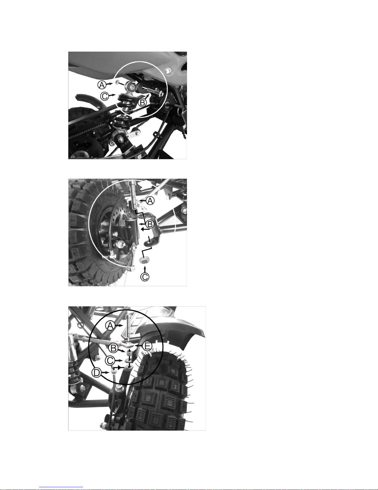
ASSEMBLY REAR SHOCKER
A: Nut M8 1pcs
B: Bolt M8×40 1pcs
C: Rear shock
1. Uplift the frame to align the shock (C)
mounting hole to the shackle joint hole.
2. Fix the bolt (B) through the shock
mounting hole and shack joint and
tighten the nut (A) securely with 10mm
-13mm open end wrench
ASSEMLY FRONT WHEEL
A: Bolt M10×90 2pcs
B: Wheel suspension left and right
C: Nut M10 2pcs
1. Put the front wheel suspension (B) into the
front swing arm joint, align the bearing
hole to the joint upper and bottom hole.
2. Mount the bolt (A) through the hole and
twist the nut (C),tighten it securely with
17mm open end wrench and 8mm allen
wrench.
ASSEBMLY TIE ROD
A :Bolt M8×40 2pcs
B: Bush Φ10×1.5×10 2pcs
C: Bracket left and right 2pcs
D :Nut M8 2pcs
E. Tie rod left and right 2pcs
1. Align the hole of tie rod end ball (E),
bush(B), bracket of mudguard(C) in
sequence.
2.Mount the bolt(A) and tighten the nut (D)
securely with 13mm open end wrench and
6mm allen wrench.
Page 10
9
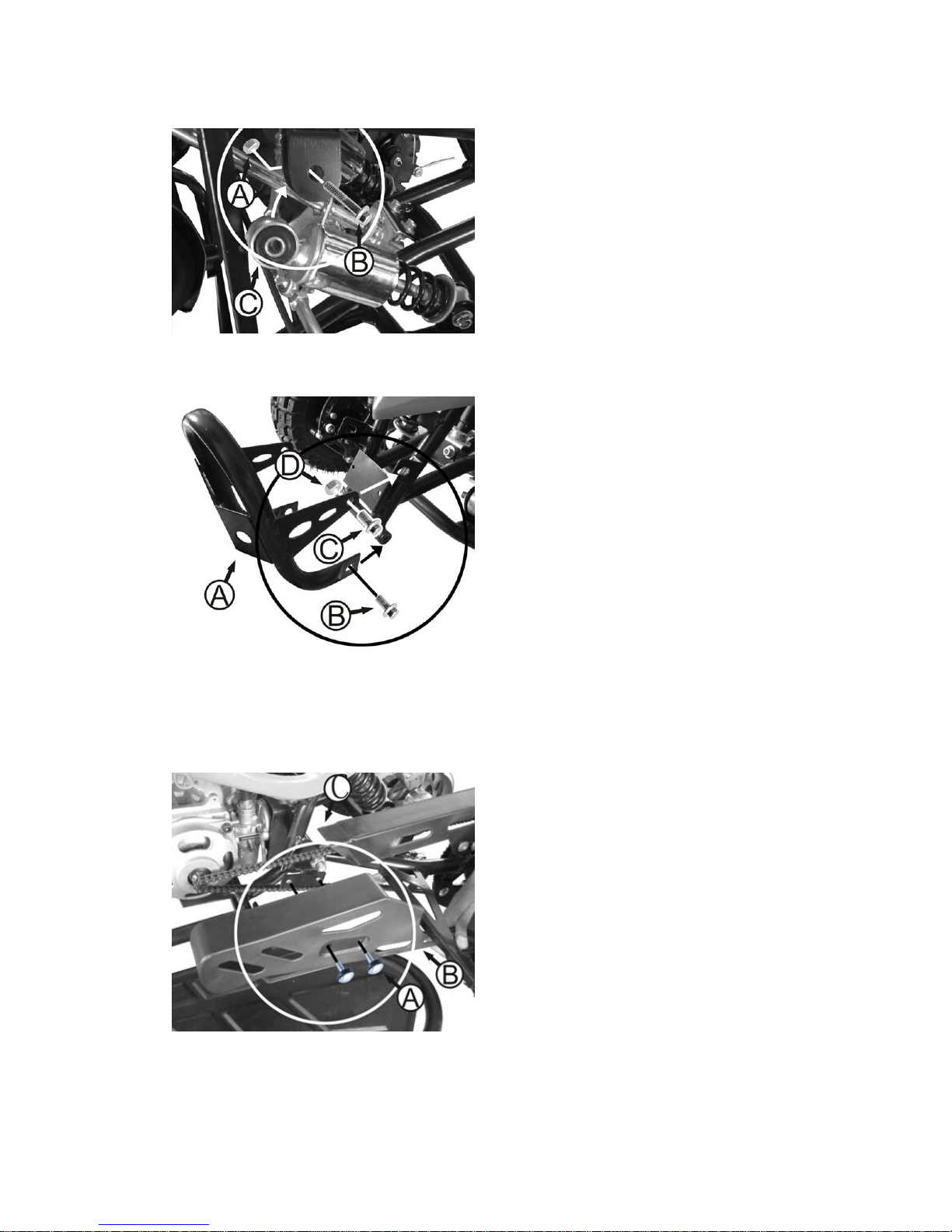
ASSEBMLY FRONT SHOCK
A:Nut M8 1pcs
B:Bolt M8×40 1pcs
C:Front shock
1. Uplift the frame to align the shock (3)
mounting hole to the shackle joint hole.
2. Fix the bolt (2) through the shock
mounting hole and shack joint and tighten
the nut (1) securely with 10mm and 13mm
open end wrench.
ASSEMLY BUMPER
A: Bumper
B: Bolt M8×16 2pcs
C: Bolt M8×16 2pcs
D: Nut M8 4pcs
1. Align the bottom mounting hole of
bumper (A) to the frame bottom joint and
mount the bolt (B), NOT tighten the bolt to
keep the bumper free move.
2. Turn upwards the bumper to align the
upper mounting hole of bumper to the
frame upper joint, then mount the bolt (C)
and twist the nut (D).
3. Tighten the bolt (B) and nut(D) securely
with10mm and 13mm open end wrench
ASEEMBLY CHAIN COVER
A: Bolt M6×16 2pcs
B: Front chain cover
C: Rear chain cover
1.Put the front part of chain cover (B)
combine with the rear part of chain cover
(C) and make sure the chain is well
covered.
2 .Install the 2pcs bolt (A) into the bracket
and tighten it securely with allen wrench
5mm.
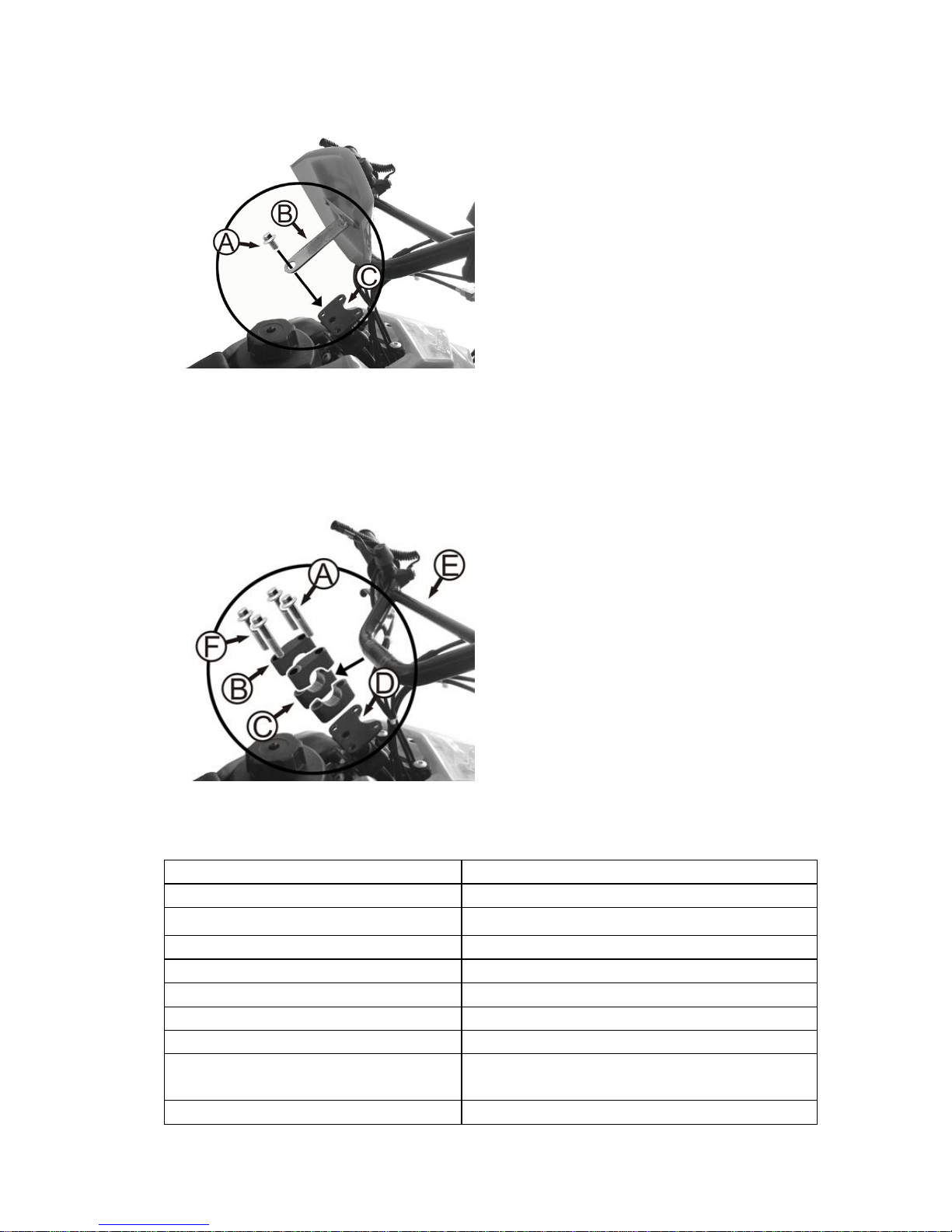
ASSEMBLY NUMBER BOARD
Page 11
10
A: Bolt M8×16 1pcs
B: Number board bracket
C: Steering rod plate
1. Place the bracket (B) on the steering rod
plate (C) with the hole in alignment.
2. Install the bolt (A) and tighten it
with 10mm open end wrench
ASSEMBLY HANDLEBAR
WARNING:
Failing to properly adjust and tighten the bolts that affix the handlebars can cause you to lose
control and crash.
A: Bolt M8×50 4pcs
B: Upper Clamp
C: Bottom Clamp
D: Steering rod bracket
E: Handle bar
1. Put the bottom clamp(C) on the steering
rod plate(D) with the screw hole in
alignment, and place the handlebar (E) in
the bottom clamp, then cover the upper
clamp (B) on the handlebar and install the
4pcs bolt (A).
2. Place the handlebar in the upright and
vertical position, then tighten all the bolts
securely with 10mm socket spanner.
TECHNICAL SPECIFICATION SHEET
Engine type
single cylinder, 2 stroke, forced air cooling
Power output
2.0kw/7500rpm
Max torque
2.3 N.m/3600rpm
Displacement (ml)
44
Fuel
Petrol mixed with 4% 2-stroke engine oil
Compression Ratio
7.5 : 1
Transmission
automatic with centrifugal clutch
Start method
manual pull start
Optional / battery
12V 4AH (only available in mini ATV with electric
starter)
Max speed (km/h)
32
Page 12
11
Front suspension
double mechanical damper
Rear suspension
mono shock absorber
Tyre (standard 4”)
front & rear 3.00-4 with 4.00 P.s.i operation pressure
and 24 P.s.i Max. inflate
Tyre (optional 6”)
front 4.10-6 with 7.00 P.s.i. operation pressure and 20
P.s.i. Max. inflate , rear 13.00 x 5-6 with 7.00 P.s.i.
operation pressure and 20 P.s.i Max. inflate .
Brake system
front and rear disc brake with mechanical control
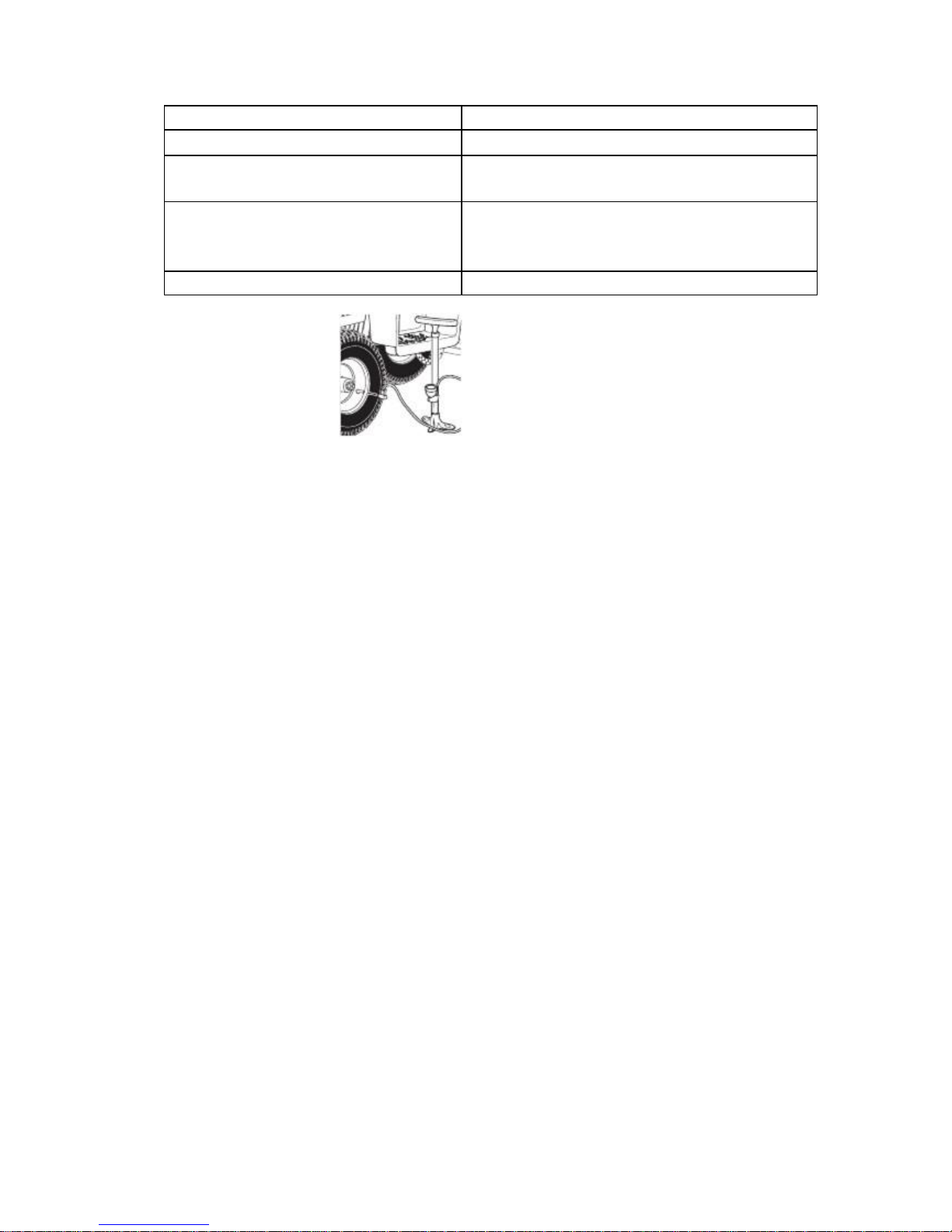
Inflating the Tires
NOTE: The 6” rear tires are inflated when shipped, but they invariably lose some pressure
between the point of manufacturing and your purchase. Be sure to inflate the tires to the
correct PSI before first time use.
Please read the specification sheet to get the information of tire pressure.
Using a bicycle-style tire pump to inflate the tire to the PSI indicated on the sidewall of the tire.
Note: The pressurized air supplies found at gasoline stations are designed to inflate
high-volume automobile tires. If you decide to use such an air supply to inflate your tires, first
make sure the pressure gauge is working, then use very
short bursts to inflate to the correct PSI. If you inadvertently over-inflate the tire, release the
excess pressure immediately.
Important information of use guider for tire
Note: Tire is the only contact surface between the vehicle to the road, the safety of various
riding activity depends on the small surface of tire where contact with the road. Therefore, it is
very important to keep the tire in good condition any time and use the correct size and
standard tire to replace the used ones.
Guide:
Tire assembly and disassembly
It is strongly recommended that the tire assembly and disassembly should be done by an
authorized technician with necessary skills.
Tire inflating pressure
It is very important to keep the tire in proper pressure and check the tire pressure before use.
The inflating should be done while the tire is cold.
Tire maintenance
Tire tread depth should be checked regularly.( Shallower tread means less grip of tire). You
must stop to use the vehicle if the tire is pierced, disassemble the tire and check it carefully.
Tire maintenance should be done by an authorized technician. Tire should be replaced
immediately when it is distorted or damaged.
Tire replacement
Page 13
12
It is important to use the correct size and standard tire as per our specification (see details in
technical specification sheet)
Don’t use the used tire if you are not sure its previous service condition.
Tire aging
Tire aging is unavoidable even the tire is not ever used or just used a few times. Tire aging is
mainly reflected in the cracked section on side of tire and tire tread, sometimes the tire is
distorted as well. The used and aged tire should be checked and confirmed if it is ok to use
again by an authorized technician
● Checks and maintenance before and after off-road use
In order to avoid problems connected to the operation of the vehicle, it is advisable to perform
a number of checks and maintenance operations before and after use. Just a few minutes
given to these procedures will save you time and money, and will make riding much safer.
Proceed as follows:
· Check pressure, general condition and thickness of tread.
· On cold days, warm up the engine by running it at idle speed for a few minutes before
starting off.
· Wash the vehicle carefully after every off-road use.
● Fueling operations
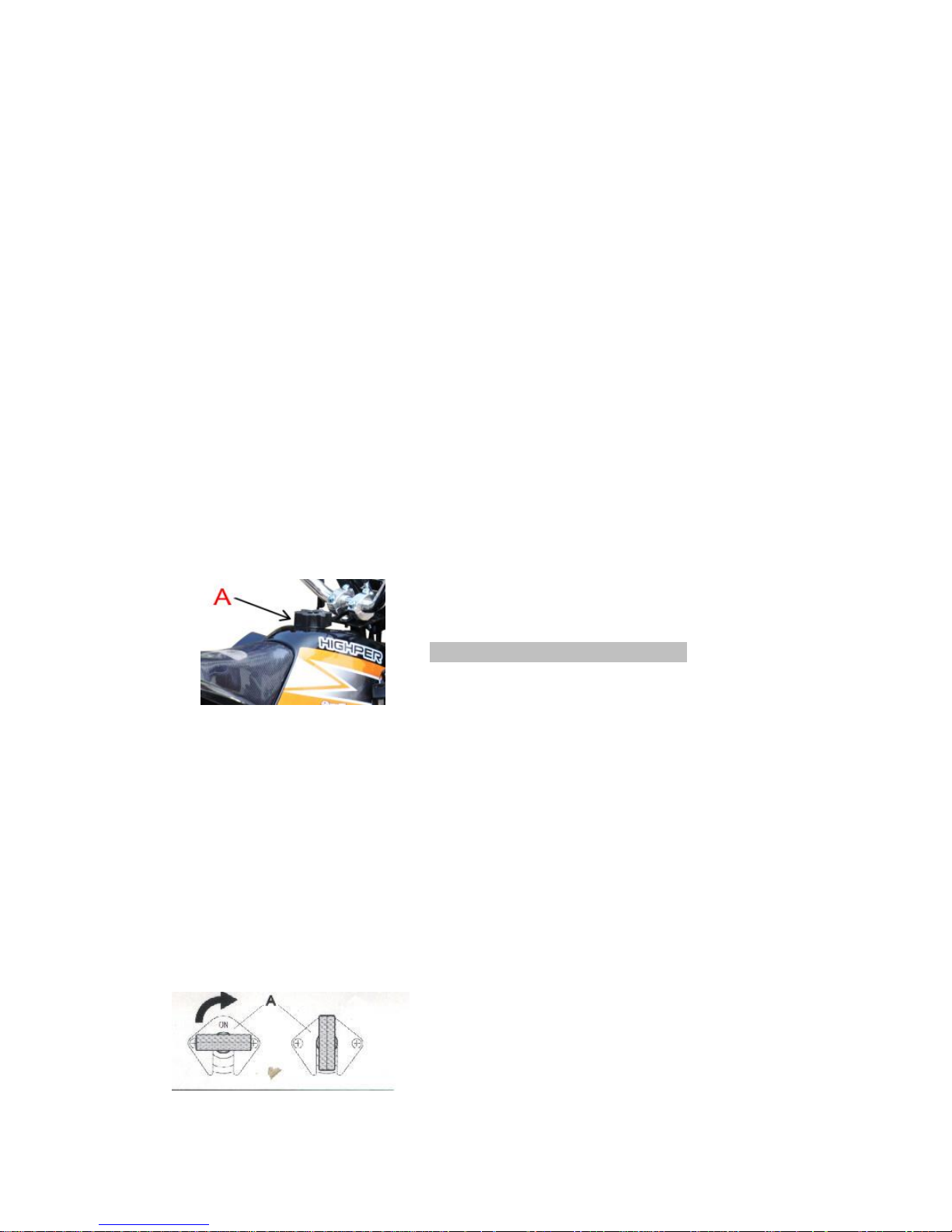
Remove cap A counterclockwise.
The fuel tank will hold approximately 1.5 liter.
Only use green fuel mixture with 4% oil.
● Breaking in
During the first 25 hours of operation running-in, the following precautions should be used;
- Avoid travel at high speeds
- Change speed often so that the parts will break in uniformly and in a shorter time
- Avoid turning the throttle more that 3/4 of the way.
WARNING
·Change the crankcase oil after 500km.
·Always use a mixture of green grade gas and a qualitatively good oil.
·After the first off-road use, check all of the nuts and bolts.
● Startup
Page 14
13
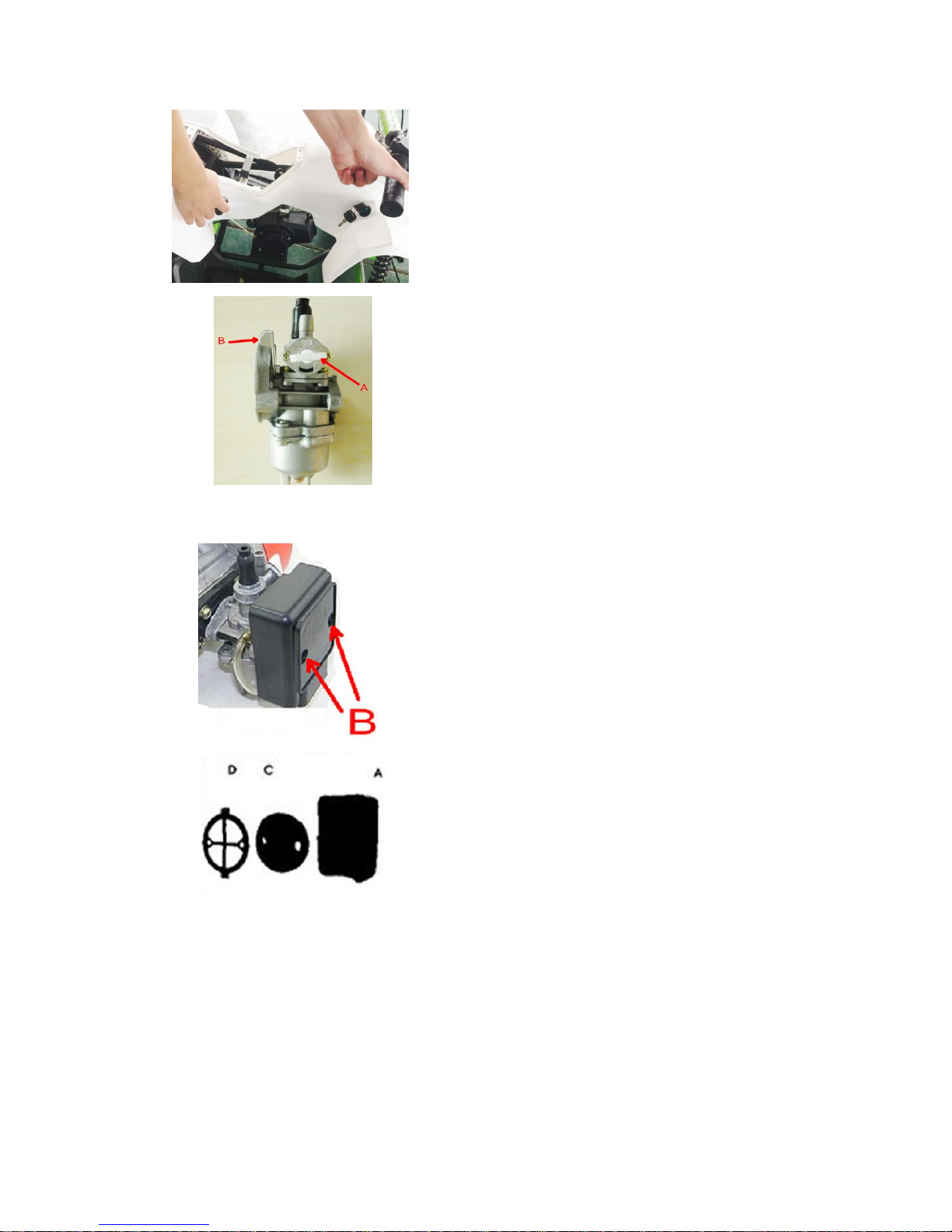
Manual hand pull
- Open fuel tank valve A ON = open
- Pull the starter as shown in the figure while slightly
turning the throttle twist grip.
- Always close the fuel tank valve when the engine is
off.
Note:
With the engine is cold, act on the starter by pushing
down lever B, wait for a short and then reposition the
lever to its former position.
● Air filter
Air filter box A is fitted directly on the carburetor.
To remove the box, undo the two screws B.
The filter box contains filter element C and support D
Note:
If filter C is very dirty, wash it in shampoo and water
and then reinsert it into its casing.
Clean the filter every time the vehicle is used
cross country.
● Spark plug
Keeping the spark plug in good condition will reduce fuel consumption and increase engine
performance.
To perform the check, simply slide off the electrical connection tube and unscrew the spark
plug. Examine the distance between the electrodes with a feeler. This distance should be from
0.5 to 0.6 mm. If it is not, it may be corrected by bending the earth electrode.
Check as well that there are on cracks in the insulation or corroded electrodes. If so, replace
immediately.
Page 15
14
When replacing the spark plug, screw it in by hand until it stops, then tighten with a wrench.
● Brakes
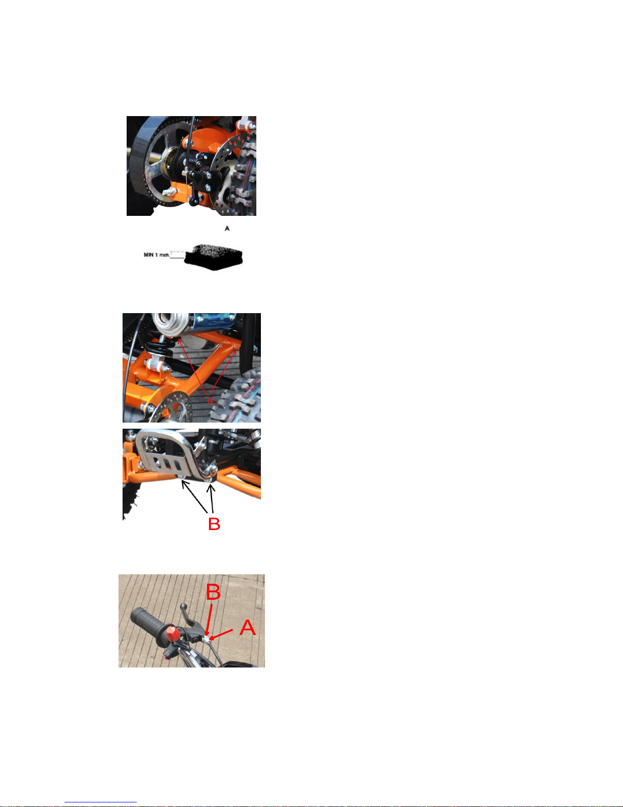
To check the wear of front and rear brake pads A,
simply inspect the brakes calipers as shown in the
figure.
The thickness of the lining on the ends of the four
pads should never be less than 1mm.
Should the lining be thinner, immediately replace the
brake pads.
We recommend having the brake pads
replaced by an authorized dealer
● Check after cleaning
After cleaning the motorcycle, it is good practice to:
· Take off the flywheel cover and remove any dirt
and water.
· Apply the lubricant above articulation points A and
B on the rear and front swing arm .
· Carefully clean and dry the chain-gear-position
assembly and then apply grease thoroughly in order
keep these parts in good condition as long as
possible.
· Dry well any metal parts subject to corrosion,
oxidation, etc.
● Adjustment
The front and rear brakes are mechanically operated
disc brakes, which require periodic adjustment.
As shown in the figure, there should be 5-6 mm play.
To adjust the play, follow these steps:
-Check the play in driving position.
-If the clearance is excessive, use adjuster A on the
brake lever to obtain the desired position.
-Tighten locknut B.
Page 16
15
Note:
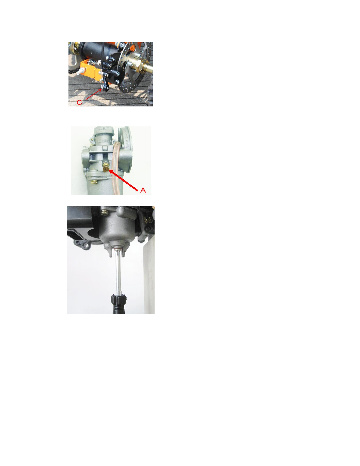
The front and rear brake calipers are equipped
with an adjuster C that allows the braking action to be
adjusted by moving the brake lever towards or away
from the disc.
Note:
To adjust the tension of the brakes cables, loosen
self-locking nut C, adjust the cable length and then
fasten C again.
ADJUSTMENT OF IDLING SPEED
In order to perform this operation correctly, we advise
you to do it when the engine is hot, connecting an
electric revolution counter to the spark plug wire. Then
use a screwdriver on register screw A to calibrate the
minimum.
CAUTION!
Always release the remaining fuel from the carburetor
after use every time following the below steps
1. Use a screwdriver to screw out the drain plug at
the bottom of carburetor.
2. Release the remaining fuel.
Use a screwdriver to tighten the drain plug securely.
Page 17

16
TROUBLESHOOTING
PROBLEM
CAUSE
REMEDY
The engine doesn’t
start
-Fuel system(tubes, fuel tank, valve) is
blocked
Clean the system
-No current arriving at spark plug
Clean or replace spark plug. If the
problem persists, consult one of our
Authorized Dealers
-Engine is flooded
With gas completely open, continue
trying to start engine for a few
Moments. If engine still doesn’t start,
remove the spark plug and dry it off.
Engine misfires
-Spark plug has irregular electrode
distance
Restore correct distance
-Spark pug is dirty
Clean or replace
Engine overheats
and loses power
-Silencer partially obstructed
Contact an authorized dealer
-Exhaust clearance partially obstructed
-Mix too lean
-Delayed ignition
Contact an authorized dealer
Jet may be partially obstructed
Contact an authorized dealer
Weak brake
-Worn Brake pads
Contact an authorized dealer
Page 18
17
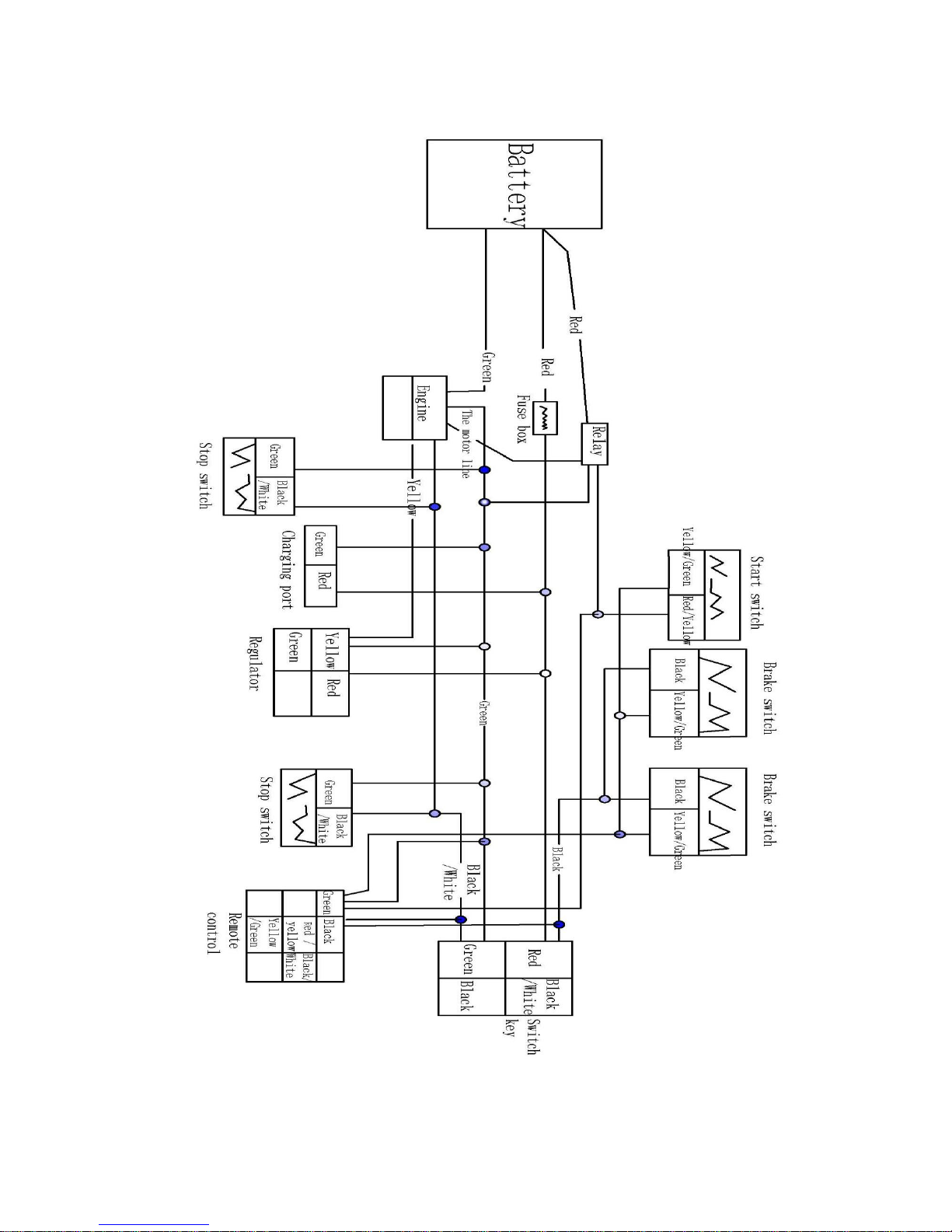
CIRCUIT DIAGRAM FOR ELECTRIC START MODEL
Page 19
18
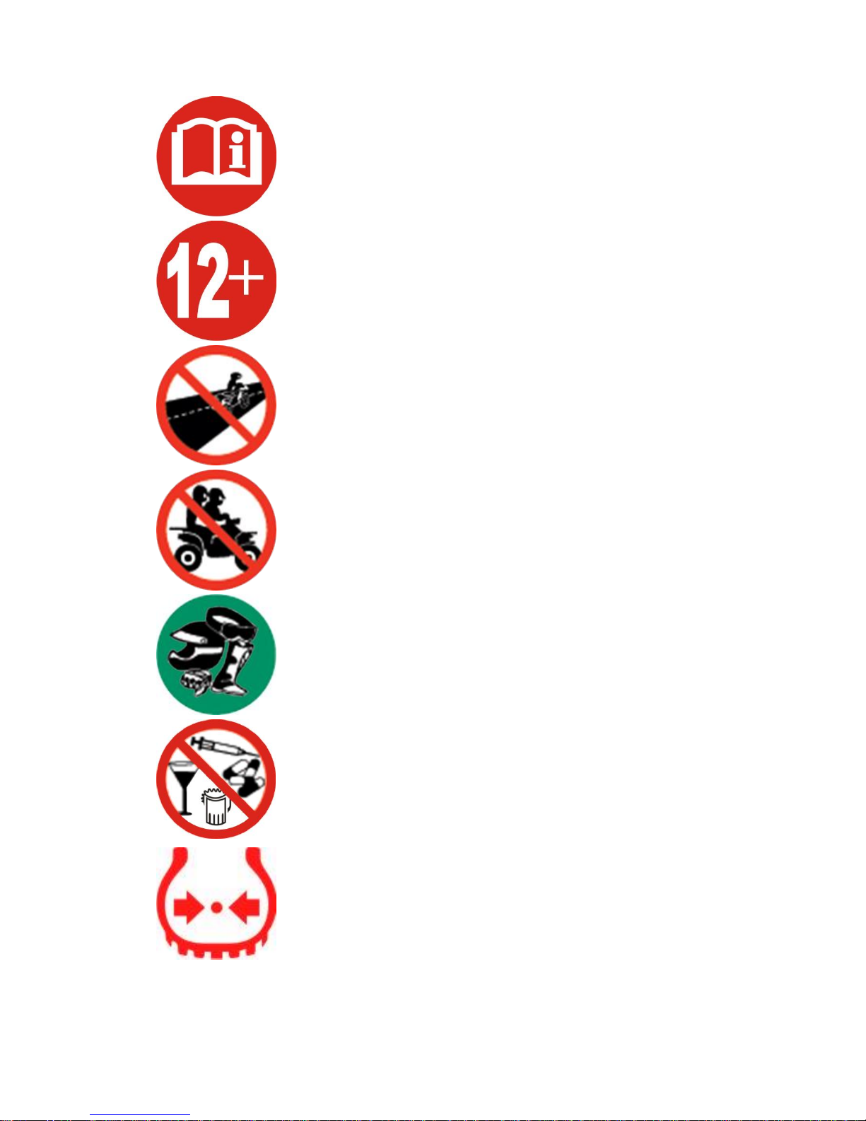
Please read the owner’s manual before riding.
Never operate this vehicle if you are under age 12.
Never use the vehicle on public road. OFF ROAD use only.
Never ride with a passenger
Always use an approved helmet and protective gear
NEVER use with drugs or alcohol
Cold tire pressure.
 Loading...