

Page 1
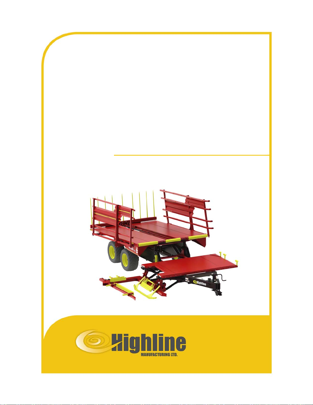
Bale Stacker
FaStack 1800/1200
O p e r a t o r s M a n u a l
E16221V1_C
Page 2

FaStack Bale Stacker 1800
FaStack Bale Stacker
1200 Flex
Operator’s
Manual
From Serial No: 19S1200000
From Serial No: 19S1800000
Highline Manufacturing Limited
HWY #27, P.O. Box 307
Vonda, SK S0K 4N0
Canada
Phone: 306.258.2233
Fax: 306.258.2010
Toll Free: 1.800.665.2010
E16221V1_C
Printed in Canada Copyright © 2019 by Highline Manufacturing Ltd. All rights reserved.
The content of this manual was based on the most current information available as of the date of copyright. It is the policy of
Highline Manufacturing Limited to improve and develop our products continually. We reserve the right to make changes or add
improvements, at any time, without incurring any obligation to make changes or improvements on machines previously sold.
Changes may not be reflected in this manual.
Page 3

Highline Manufacturing Ltd. FaStack Bale Stacker 1800/1200 Flex
Highline Team Message
Congratulations on your purchase of the FaStack Bale Stacker 1800/1200 Flex manufactured
by Highline Manufacturing Ltd.
This Operator’s Manual has been prepared to provide information necessary for the safe and
efficient operation of your Bale Stacker. In the manual you will find safety procedures,
maintenance routines and detailed operational instructions.
If you find that you require information not covered in this manual, please feel free to consult
your local dealer. Your dealer is always able to contact Highline for this technical information.
Highline Manufacturing Ltd. thanks and congratulates you for selecting a FaStack Bale Stacker
1800/1200 Flex as your machine of choice.
Highline Manufacturing Ltd.
Page 4

Table of Contents
Section 1 - Safety
Serial Number . . . . . . . . . . . . . . . . . . . . . . . . . . . . . . . . . . . . . . . . . . . . . . . . . . . . . . . . . . . . . . . . . . . . . . . . . 1
Safety Sign-off Form . . . . . . . . . . . . . . . . . . . . . . . . . . . . . . . . . . . . . . . . . . . . . . . . . . . . . . . . . . . . . . . . . . . . 2
Safety Alert Symbol . . . . . . . . . . . . . . . . . . . . . . . . . . . . . . . . . . . . . . . . . . . . . . . . . . . . . . . . . . . . . . . . . . . . . 3
General Safety . . . . . . . . . . . . . . . . . . . . . . . . . . . . . . . . . . . . . . . . . . . . . . . . . . . . . . . . . . . . . . . . . . . . . . . . . 4
Safety Decals . . . . . . . . . . . . . . . . . . . . . . . . . . . . . . . . . . . . . . . . . . . . . . . . . . . . . . . . . . . . . . . . . . . . . . . . . . 4
Safety Decal Locations - Fastack 1800 . . . . . . . . . . . . . . . . . . . . . . . . . . . . . . . . . . . . . . . . . . . . . . . . . . . . . . 9
Safety Decal Locations - Fastack 1200 Flex . . . . . . . . . . . . . . . . . . . . . . . . . . . . . . . . . . . . . . . . . . . . . . . . . 11
Section 2 - FaStack Display and Joystick
FaStack Display . . . . . . . . . . . . . . . . . . . . . . . . . . . . . . . . . . . . . . . . . . . . . . . . . . . . . . . . . . . . . . . . . . . . . . . . 1
Joystick . . . . . . . . . . . . . . . . . . . . . . . . . . . . . . . . . . . . . . . . . . . . . . . . . . . . . . . . . . . . . . . . . . . . . . . . . . . . . . 1
Software Menu Tree . . . . . . . . . . . . . . . . . . . . . . . . . . . . . . . . . . . . . . . . . . . . . . . . . . . . . . . . . . . . . . . . . . . . 2
Home Screen for 1800 and 1200 Flex . . . . . . . . . . . . . . . . . . . . . . . . . . . . . . . . . . . . . . . . . . . . . . . . . . . . . . . 3
# of Bales . . . . . . . . . . . . . . . . . . . . . . . . . . . . . . . . . . . . . . . . . . . . . . . . . . . . . . . . . . . . . . . . . . . . . . . . . . . . 3
Transport Mode . . . . . . . . . . . . . . . . . . . . . . . . . . . . . . . . . . . . . . . . . . . . . . . . . . . . . . . . . . . . . . . . . . . . . . . . 3
Loading Arm Auto . . . . . . . . . . . . . . . . . . . . . . . . . . . . . . . . . . . . . . . . . . . . . . . . . . . . . . . . . . . . . . . . . . . . . . 4
Auto Sequence Active . . . . . . . . . . . . . . . . . . . . . . . . . . . . . . . . . . . . . . . . . . . . . . . . . . . . . . . . . . . . . . . . . . . 5
Front Table Auto - 1800 . . . . . . . . . . . . . . . . . . . . . . . . . . . . . . . . . . . . . . . . . . . . . . . . . . . . . . . . . . . . . . . . . . 5
Front Table Auto - 1200 . . . . . . . . . . . . . . . . . . . . . . . . . . . . . . . . . . . . . . . . . . . . . . . . . . . . . . . . . . . . . . . . . . 6
Front Table Rotate . . . . . . . . . . . . . . . . . . . . . . . . . . . . . . . . . . . . . . . . . . . . . . . . . . . . . . . . . . . . . . . . . . . . . 6
Menu Screen Selections . . . . . . . . . . . . . . . . . . . . . . . . . . . . . . . . . . . . . . . . . . . . . . . . . . . . . . . . . . . . . . . . . 7
Display Settings . . . . . . . . . . . . . . . . . . . . . . . . . . . . . . . . . . . . . . . . . . . . . . . . . . . . . . . . . . . . . . . . . . . 7
Controller Settings . . . . . . . . . . . . . . . . . . . . . . . . . . . . . . . . . . . . . . . . . . . . . . . . . . . . . . . . . . . . . . . . . 8
Sensor Statuses . . . . . . . . . . . . . . . . . . . . . . . . . . . . . . . . . . . . . . . . . . . . . . . . . . . . . . . . . . 8
Adjust Setpoints . . . . . . . . . . . . . . . . . . . . . . . . . . . . . . . . . . . . . . . . . . . . . . . . . . . . . . . . . . . 9
Restore Default Settings . . . . . . . . . . . . . . . . . . . . . . . . . . . . . . . . . . . . . . . . . . . . . . . . . . . 10
Adjust Setpoint Descriptions . . . . . . . . . . . . . . . . . . . . . . . . . . . . . . . . . . . . . . . . . . . . . . . . 11
Manual Hydraulic Control . . . . . . . . . . . . . . . . . . . . . . . . . . . . . . . . . . . . . . . . . . . . . . . . . . . . . . . . . . . 13
Front Table Rotate . . . . . . . . . . . . . . . . . . . . . . . . . . . . . . . . . . . . . . . . . . . . . . . . . . . . . . . . 13
Flipper . . . . . . . . . . . . . . . . . . . . . . . . . . . . . . . . . . . . . . . . . . . . . . . . . . . . . . . . . . . . . . . . . 13
Lockout Over-ride . . . . . . . . . . . . . . . . . . . . . . . . . . . . . . . . . . . . . . . . . . . . . . . . . . . . . . . . 13
Information . . . . . . . . . . . . . . . . . . . . . . . . . . . . . . . . . . . . . . . . . . . . . . . . . . . . . . . . . . . . . . . . . . . . . . . . . . . 14
Total Bales . . . . . . . . . . . . . . . . . . . . . . . . . . . . . . . . . . . . . . . . . . . . . . . . . . . . . . . . . . . . . . . . . . . . . . 14
Section 3 - Transporting the Bale Stacker
Tractor requirements . . . . . . . . . . . . . . . . . . . . . . . . . . . . . . . . . . . . . . . . . . . . . . . . . . . . . . . . . . . . . . . . . . . . 1
Lift the hitch . . . . . . . . . . . . . . . . . . . . . . . . . . . . . . . . . . . . . . . . . . . . . . . . . . . . . . . . . . . . . . . . . . . . . . . . . . . 1
Adjust the position of the hitch clevis . . . . . . . . . . . . . . . . . . . . . . . . . . . . . . . . . . . . . . . . . . . . . . . . . . . . . . . . 2
Connect the hitch to the tractor drawbar. . . . . . . . . . . . . . . . . . . . . . . . . . . . . . . . . . . . . . . . . . . . . . . . . . . . . . 2
Connect the safety chain to the tractor . . . . . . . . . . . . . . . . . . . . . . . . . . . . . . . . . . . . . . . . . . . . . . . . . . . . . . 2
Place the hitch jack in the storage position . . . . . . . . . . . . . . . . . . . . . . . . . . . . . . . . . . . . . . . . . . . . . . . . . . . 2
Attach the hydraulic hoses . . . . . . . . . . . . . . . . . . . . . . . . . . . . . . . . . . . . . . . . . . . . . . . . . . . . . . . . . . . . . . . . 3
Connect the lighting cable . . . . . . . . . . . . . . . . . . . . . . . . . . . . . . . . . . . . . . . . . . . . . . . . . . . . . . . . . . . . . . . . 3
Route the cab harness . . . . . . . . . . . . . . . . . . . . . . . . . . . . . . . . . . . . . . . . . . . . . . . . . . . . . . . . . . . . . . . . . . . 3
Place the joystick and display in the tractor cab . . . . . . . . . . . . . . . . . . . . . . . . . . . . . . . . . . . . . . . . . . . . . . . 3
Connect the joystick to the harness connection. . . . . . . . . . . . . . . . . . . . . . . . . . . . . . . . . . . . . . . . . . . . . . . 4
Connect the display to the harness connection. . . . . . . . . . . . . . . . . . . . . . . . . . . . . . . . . . . . . . . . . . . . . . . . 4
Connect the power cord into the key and constant 12V DC power supply . . . . . . . . . . . . . . . . . . . . . . . . . . . 4
If needed, select for Open Center Hydraulics . . . . . . . . . . . . . . . . . . . . . . . . . . . . . . . . . . . . . . . . . . . . . . . . . 5
Touch the Load button on the Home Screen . . . . . . . . . . . . . . . . . . . . . . . . . . . . . . . . . . . . . . . . . . . . . . . . . 5
Activate the hydraulics and lock the control valve . . . . . . . . . . . . . . . . . . . . . . . . . . . . . . . . . . . . . . . . . . . . . 6
Lift arm cylinder locks . . . . . . . . . . . . . . . . . . . . . . . . . . . . . . . . . . . . . . . . . . . . . . . . . . . . . . . . . . . . . . . . . . . 6
Lower the lift arm . . . . . . . . . . . . . . . . . . . . . . . . . . . . . . . . . . . . . . . . . . . . . . . . . . . . . . . . . . . . . . . . . . . . . . 6
Lower the front table . . . . . . . . . . . . . . . . . . . . . . . . . . . . . . . . . . . . . . . . . . . . . . . . . . . . . . . . . . . . . . . . . . . . 7
Page 5

Touch the Unload button on the display . . . . . . . . . . . . . . . . . . . . . . . . . . . . . . . . . . . . . . . . . . . . . . . . . . . . . 7
Lower the rear table . . . . . . . . . . . . . . . . . . . . . . . . . . . . . . . . . . . . . . . . . . . . . . . . . . . . . . . . . . . . . . . . . . . . . 7
Check the condition of all the tires . . . . . . . . . . . . . . . . . . . . . . . . . . . . . . . . . . . . . . . . . . . . . . . . . . . . . . . . . . 8
Touch the Load button on the display . . . . . . . . . . . . . . . . . . . . . . . . . . . . . . . . . . . . . . . . . . . . . . . . . . . . . . . 8
Close the clamp . . . . . . . . . . . . . . . . . . . . . . . . . . . . . . . . . . . . . . . . . . . . . . . . . . . . . . . . . . . . . . . . . . . . . . . . 8
Raise the lift arm using the joystick button . . . . . . . . . . . . . . . . . . . . . . . . . . . . . . . . . . . . . . . . . . . . . . . . . . . . 9
Remove the front lift arm transport lock from the storage position . . . . . . . . . . . . . . . . . . . . . . . . . . . . . . . . . 9
Install the front lift arm transport lock . . . . . . . . . . . . . . . . . . . . . . . . . . . . . . . . . . . . . . . . . . . . . . . . . . . . . . . 9
Remove the rear lift arm transport lock from the storage position . . . . . . . . . . . . . . . . . . . . . . . . . . . . . . . . . 10
Install the rear lift arm transport lock . . . . . . . . . . . . . . . . . . . . . . . . . . . . . . . . . . . . . . . . . . . . . . . . . . . . . . . 10
Move the bale trolley to the front of the table . . . . . . . . . . . . . . . . . . . . . . . . . . . . . . . . . . . . . . . . . . . . . . . . . 10
Ensure that the Slow Moving Vehicle (SMV) sign and lights are clean and visible. . . . . . . . . . . . . . . . . . . . . 11
Ensure the lights are working. . . . . . . . . . . . . . . . . . . . . . . . . . . . . . . . . . . . . . . . . . . . . . . . . . . . . . . . . . . . . 11
Transport Speed . . . . . . . . . . . . . . . . . . . . . . . . . . . . . . . . . . . . . . . . . . . . . . . . . . . . . . . . . . . . . . . . . . . . . . . 11
If traveling on roadways: . . . . . . . . . . . . . . . . . . . . . . . . . . . . . . . . . . . . . . . . . . . . . . . . . . . . . . . . . . . . . . . . . 11
Section 4 - Preparing the Bale Stacker
Park the tractor and bale stacker on level ground. . . . . . . . . . . . . . . . . . . . . . . . . . . . . . . . . . . . . . . . . . . . . . 1
Check that the frame is 22" (559 mm) off the ground. . . . . . . . . . . . . . . . . . . . . . . . . . . . . . . . . . . . . . . . . . . . 1
Attach the hydraulic hoses . . . . . . . . . . . . . . . . . . . . . . . . . . . . . . . . . . . . . . . . . . . . . . . . . . . . . . . . . . . . . . . . 1
Connect the lighting cable . . . . . . . . . . . . . . . . . . . . . . . . . . . . . . . . . . . . . . . . . . . . . . . . . . . . . . . . . . . . . . . . 2
Remove the front transport lock . . . . . . . . . . . . . . . . . . . . . . . . . . . . . . . . . . . . . . . . . . . . . . . . . . . . . . . . . . . 2
Remove the rear transport lock . . . . . . . . . . . . . . . . . . . . . . . . . . . . . . . . . . . . . . . . . . . . . . . . . . . . . . . . . . . . 2
Connect the tractor harness to the stacker harness located on the hitch. . . . . . . . . . . . . . . . . . . . . . . . . . . . . 3
Connect the power cord into the keyed and constant 12V DC . . . . . . . . . . . . . . . . . . . . . . . . . . . . . . . . . . . . 3
If needed, select for Open Center Hydraulics . . . . . . . . . . . . . . . . . . . . . . . . . . . . . . . . . . . . . . . . . . . . . . . . . 3
Touch the Load button on the Home Screen . . . . . . . . . . . . . . . . . . . . . . . . . . . . . . . . . . . . . . . . . . . . . . . . . 4
Lower the lift arm. . . . . . . . . . . . . . . . . . . . . . . . . . . . . . . . . . . . . . . . . . . . . . . . . . . . . . . . . . . . . . . . . . . . . . . . 5
Check the condition of the rotation sensor . . . . . . . . . . . . . . . . . . . . . . . . . . . . . . . . . . . . . . . . . . . . . . . . . . . 5
Adjust the lift arm for the size of the bales . . . . . . . . . . . . . . . . . . . . . . . . . . . . . . . . . . . . . . . . . . . . . . . . . . . . 6
FaStack 1200 Flex adjust the spring loaded bar . . . . . . . . . . . . . . . . . . . . . . . . . . . . . . . . . . . . . . . . . . . . . . . 6
Check that the lift arm operates freely . . . . . . . . . . . . . . . . . . . . . . . . . . . . . . . . . . . . . . . . . . . . . . . . . . . . . . . 7
FaStack 1200 Flex check that the front table rotates freely . . . . . . . . . . . . . . . . . . . . . . . . . . . . . . . . . . . . . . . 7
Check that the front table raises and lowers freely . . . . . . . . . . . . . . . . . . . . . . . . . . . . . . . . . . . . . . . . . . . . . 8
Check that the rear table raises and lowers freely. . . . . . . . . . . . . . . . . . . . . . . . . . . . . . . . . . . . . . . . . . . . . . 9
FaStack 1200 Flex - Check that the pushoffs fully extend and retract . . . . . . . . . . . . . . . . . . . . . . . . . . . . . . 10
Check that the bale trolley on the rear table operates freely . . . . . . . . . . . . . . . . . . . . . . . . . . . . . . . . . . . . . 10
Check that the side racks open and close . . . . . . . . . . . . . . . . . . . . . . . . . . . . . . . . . . . . . . . . . . . . . . . . . . . 11
Check the condition of the tires . . . . . . . . . . . . . . . . . . . . . . . . . . . . . . . . . . . . . . . . . . . . . . . . . . . . . . . . . . . 11
Inspect all the hydraulic cylinders and hoses . . . . . . . . . . . . . . . . . . . . . . . . . . . . . . . . . . . . . . . . . . . . . . . . . 11
Section 5 - Operating the Bale Stacker
Tractor Hitch Category Requirement . . . . . . . . . . . . . . . . . . . . . . . . . . . . . . . . . . . . . . . . . . . . . . . . . . . . . . . . 1
Number Of Bales Capacity . . . . . . . . . . . . . . . . . . . . . . . . . . . . . . . . . . . . . . . . . . . . . . . . . . . . . . . . . . . . . . . . 2
"On Strings" or "Off Strings" Stacking . . . . . . . . . . . . . . . . . . . . . . . . . . . . . . . . . . . . . . . . . . . . . . . . . . . . . . . 3
Loading Bales in the Field
Drive the bale stacker into the field area . . . . . . . . . . . . . . . . . . . . . . . . . . . . . . . . . . . . . . . . . . . . . . . . . . . . . 4
Park on level ground. . . . . . . . . . . . . . . . . . . . . . . . . . . . . . . . . . . . . . . . . . . . . . . . . . . . . . . . . . . . . . . . . . . . . 4
Engage the hydraulic lever and lock it in the open position. . . . . . . . . . . . . . . . . . . . . . . . . . . . . . . . . . . . . . . . 4
Touch the Load Button . . . . . . . . . . . . . . . . . . . . . . . . . . . . . . . . . . . . . . . . . . . . . . . . . . . . . . . . . . . . . . . . . . 4
Remove the front transport lock . . . . . . . . . . . . . . . . . . . . . . . . . . . . . . . . . . . . . . . . . . . . . . . . . . . . . . . . . . . 4
Remove the rear transport lock . . . . . . . . . . . . . . . . . . . . . . . . . . . . . . . . . . . . . . . . . . . . . . . . . . . . . . . . . . . . 4
Loading the Front Table . . . . . . . . . . . . . . . . . . . . . . . . . . . . . . . . . . . . . . . . . . . . . . . . . . . . . . . . . . . . . . . . . . 5
Loading Arm Manual Control . . . . . . . . . . . . . . . . . . . . . . . . . . . . . . . . . . . . . . . . . . . . . . . . . . . . . . . . . . . . . . 5
Loading Arm Auto Control . . . . . . . . . . . . . . . . . . . . . . . . . . . . . . . . . . . . . . . . . . . . . . . . . . . . . . . . . . . . . . . . 7
Page 6

FaStack 1800 Front Table Raise . . . . . . . . . . . . . . . . . . . . . . . . . . . . . . . . . . . . . . . . . . . . . . . . . . . . . . . . . . . 8
FaStack 1800 Front Table Raise Manual Control . . . . . . . . . . . . . . . . . . . . . . . . . . . . . . . . . . . . . . . . . 8
FaStack 1800 Front Table Auto Raise . . . . . . . . . . . . . . . . . . . . . . . . . . . . . . . . . . . . . . . . . . . . . . . . . . 9
FaStack 1200 Front Table Raise . . . . . . . . . . . . . . . . . . . . . . . . . . . . . . . . . . . . . . . . . . . . . . . . . . . . . . . . . . 10
Manual Control Without Rotating Bales . . . . . . . . . . . . . . . . . . . . . . . . . . . . . . . . . . . . . . . . . . . . . . . . 10
Manual Control With Rotating Bales . . . . . . . . . . . . . . . . . . . . . . . . . . . . . . . . . . . . . . . . . . . . . . . . . . 11
Auto Control Without Rotating the Bales . . . . . . . . . . . . . . . . . . . . . . . . . . . . . . . . . . . . . . . . . . . . . . . 13
Auto Control With Rotating the Bales . . . . . . . . . . . . . . . . . . . . . . . . . . . . . . . . . . . . . . . . . . . . . . . . . 14
If the bales are hitting against the side racks . . . . . . . . . . . . . . . . . . . . . . . . . . . . . . . . . . . . . . . . . . . . . . . . 15
Rear Table Full Load . . . . . . . . . . . . . . . . . . . . . . . . . . . . . . . . . . . . . . . . . . . . . . . . . . . . . . . . . . . . . . . . . . . 16
If traveling on roadways . . . . . . . . . . . . . . . . . . . . . . . . . . . . . . . . . . . . . . . . . . . . . . . . . . . . . . . . . . . . . . . . . 16
Recommended Procedures for Starting A Bale Stack with
FaStack 1800 . . . . . . . . . . . . . . . . . . . . . . . . . . . . . . . . . . . . . . . . . . . . . . . . . . . . . . . . . . . . . . . . . . . 17
FaStack 1200 Bales Not Rotated . . . . . . . . . . . . . . . . . . . . . . . . . . . . . . . . . . . . . . . . . . . . . . . . . . . . . 17
FaStack 1200 With Bales Rotated . . . . . . . . . . . . . . . . . . . . . . . . . . . . . . . . . . . . . . . . . . . . . . . . . . . . 18
Unloading Bales
Lower the lift arm . . . . . . . . . . . . . . . . . . . . . . . . . . . . . . . . . . . . . . . . . . . . . . . . . . . . . . . . . . . . . . . . . . . . . 22
Push the Transport Mode . . . . . . . . . . . . . . . . . . . . . . . . . . . . . . . . . . . . . . . . . . . . . . . . . . . . . . . . . . . . . . . 22
Fully lower the front table . . . . . . . . . . . . . . . . . . . . . . . . . . . . . . . . . . . . . . . . . . . . . . . . . . . . . . . . . . . . . . . . 22
Position the stacker for unloading . . . . . . . . . . . . . . . . . . . . . . . . . . . . . . . . . . . . . . . . . . . . . . . . . . . . . . . . . 22
Open the side racks a small amount . . . . . . . . . . . . . . . . . . . . . . . . . . . . . . . . . . . . . . . . . . . . . . . . . . . . . . . 22
Begin to raise the rear table. . . . . . . . . . . . . . . . . . . . . . . . . . . . . . . . . . . . . . . . . . . . . . . . . . . . . . . . . . . . . . 22
Stop raising the table when the bales start to slide . . . . . . . . . . . . . . . . . . . . . . . . . . . . . . . . . . . . . . . . . . . . 23
Continue raising the table again with pauses while raising . . . . . . . . . . . . . . . . . . . . . . . . . . . . . . . . . . . . . . 23
Lift the rear table to the fully raised position . . . . . . . . . . . . . . . . . . . . . . . . . . . . . . . . . . . . . . . . . . . . . . . . . 24
Open the side racks when the table is raised . . . . . . . . . . . . . . . . . . . . . . . . . . . . . . . . . . . . . . . . . . . . . . . . 24
Slowly drive forward . . . . . . . . . . . . . . . . . . . . . . . . . . . . . . . . . . . . . . . . . . . . . . . . . . . . . . . . . . . . . . . . . . . 24
FaStack 1200 Flex activate the pushoffs . . . . . . . . . . . . . . . . . . . . . . . . . . . . . . . . . . . . . . . . . . . . . . . . . . . 24
Lower the table completely . . . . . . . . . . . . . . . . . . . . . . . . . . . . . . . . . . . . . . . . . . . . . . . . . . . . . . . . . . . . . . 25
Close the side racks . . . . . . . . . . . . . . . . . . . . . . . . . . . . . . . . . . . . . . . . . . . . . . . . . . . . . . . . . . . . . . . . . . . 25
Bring the trolley forward . . . . . . . . . . . . . . . . . . . . . . . . . . . . . . . . . . . . . . . . . . . . . . . . . . . . . . . . . . . . . . . . 25
:
Section 6 - Maintaining the Bale Stacker
Shutdown Procedure . . . . . . . . . . . . . . . . . . . . . . . . . . . . . . . . . . . . . . . . . . . . . . . . . . . . . . . . . . . . . . . . . . . . 1
Lubrication . . . . . . . . . . . . . . . . . . . . . . . . . . . . . . . . . . . . . . . . . . . . . . . . . . . . . . . . . . . . . . . . . . . . . . . . . . . . 1
Grease the Lift Arm Every 10 Hours . . . . . . . . . . . . . . . . . . . . . . . . . . . . . . . . . . . . . . . . . . . . . . . . . . . . . . . . 1
Grease Every 200 Hours . . . . . . . . . . . . . . . . . . . . . . . . . . . . . . . . . . . . . . . . . . . . . . . . . . . . . . . . . . . . . . . . . 3
Check the Lift Arm Rotation Sensor . . . . . . . . . . . . . . . . . . . . . . . . . . . . . . . . . . . . . . . . . . . . . . . . . . . . . . . . 8
Check the Condition of the Proximity Sensors . . . . . . . . . . . . . . . . . . . . . . . . . . . . . . . . . . . . . . . . . . . . . . . . 8
Replacing An Electrical Fuse . . . . . . . . . . . . . . . . . . . . . . . . . . . . . . . . . . . . . . . . . . . . . . . . . . . . . . . . . . . . . . 9
Visually Inspect Hydraulic Hoses/Fitting . . . . . . . . . . . . . . . . . . . . . . . . . . . . . . . . . . . . . . . . . . . . . . . . . . . . . 9
Avoid Machine Damage If Welding . . . . . . . . . . . . . . . . . . . . . . . . . . . . . . . . . . . . . . . . . . . . . . . . . . . . . . . . . 9
Tire Changing Procedure . . . . . . . . . . . . . . . . . . . . . . . . . . . . . . . . . . . . . . . . . . . . . . . . . . . . . . . . . . . . . . . . 10
Tire Pressure . . . . . . . . . . . . . . . . . . . . . . . . . . . . . . . . . . . . . . . . . . . . . . . . . . . . . . . . . . . . . . . . . . . . . . . . . 10
Page 7

Section 7 - Storing the Bale Stacker
Clean all the debris off . . . . . . . . . . . . . . . . . . . . . . . . . . . . . . . . . . . . . . . . . . . . . . . . . . . . . . . . . . . . . . . . . . . 1
Lubricate all bale stacker grease points . . . . . . . . . . . . . . . . . . . . . . . . . . . . . . . . . . . . . . . . . . . . . . . . . . . . . 1
Lubricate the bale trolley chain . . . . . . . . . . . . . . . . . . . . . . . . . . . . . . . . . . . . . . . . . . . . . . . . . . . . . . . . . . . . 1
Check the bale stacker for worn and damaged parts . . . . . . . . . . . . . . . . . . . . . . . . . . . . . . . . . . . . . . . . . . . . 1
Park the bale stacker on level ground . . . . . . . . . . . . . . . . . . . . . . . . . . . . . . . . . . . . . . . . . . . . . . . . . . . . . . . 1
Raise the rear table to make the trolley drop . . . . . . . . . . . . . . . . . . . . . . . . . . . . . . . . . . . . . . . . . . . . . . . . . . 1
Lower the rear table . . . . . . . . . . . . . . . . . . . . . . . . . . . . . . . . . . . . . . . . . . . . . . . . . . . . . . . . . . . . . . . . . . . . . 2
Lower the front table . . . . . . . . . . . . . . . . . . . . . . . . . . . . . . . . . . . . . . . . . . . . . . . . . . . . . . . . . . . . . . . . . . . . 2
Lower the lift arm. . . . . . . . . . . . . . . . . . . . . . . . . . . . . . . . . . . . . . . . . . . . . . . . . . . . . . . . . . . . . . . . . . . . . . . . 3
Open the clamp arm . . . . . . . . . . . . . . . . . . . . . . . . . . . . . . . . . . . . . . . . . . . . . . . . . . . . . . . . . . . . . . . . . . . . . 3
Lower the hitch jack . . . . . . . . . . . . . . . . . . . . . . . . . . . . . . . . . . . . . . . . . . . . . . . . . . . . . . . . . . . . . . . . . . . . . 3
Relieve the pressure on the hydraulic hoses and disconnect them . . . . . . . . . . . . . . . . . . . . . . . . . . . . . . . . . 3
Disconnect the electrical connection . . . . . . . . . . . . . . . . . . . . . . . . . . . . . . . . . . . . . . . . . . . . . . . . . . . . . . . . 3
Disconnect the tractor cable from the hitch harness. . . . . . . . . . . . . . . . . . . . . . . . . . . . . . . . . . . . . . . . . . . . 4
Secure the hydraulic hoses and electrical connector . . . . . . . . . . . . . . . . . . . . . . . . . . . . . . . . . . . . . . . . . . . 4
Disconnect the hitch . . . . . . . . . . . . . . . . . . . . . . . . . . . . . . . . . . . . . . . . . . . . . . . . . . . . . . . . . . . . . . . . . . . . 4
Disconnect the safety chain . . . . . . . . . . . . . . . . . . . . . . . . . . . . . . . . . . . . . . . . . . . . . . . . . . . . . . . . . . . . . . . 4
Section 8 - Troubleshooting
Lift Arm . . . . . . . . . . . . . . . . . . . . . . . . . . . . . . . . . . . . . . . . . . . . . . . . . . . . . . . . . . . . . . . . . . . . . . . . . . . . . . . 1
Front Table . . . . . . . . . . . . . . . . . . . . . . . . . . . . . . . . . . . . . . . . . . . . . . . . . . . . . . . . . . . . . . . . . . . . . . . . . . . . 3
Rear Table . . . . . . . . . . . . . . . . . . . . . . . . . . . . . . . . . . . . . . . . . . . . . . . . . . . . . . . . . . . . . . . . . . . . . . . . . . . . 5
Rear Table Trolley . . . . . . . . . . . . . . . . . . . . . . . . . . . . . . . . . . . . . . . . . . . . . . . . . . . . . . . . . . . . . . . . . . . . . . 6
Side Racks . . . . . . . . . . . . . . . . . . . . . . . . . . . . . . . . . . . . . . . . . . . . . . . . . . . . . . . . . . . . . . . . . . . . . . . . . . . . 7
Hydraulic Block and Valves . . . . . . . . . . . . . . . . . . . . . . . . . . . . . . . . . . . . . . . . . . . . . . . . . . . . . . . . . . . . . . . 9
Section 9 - Specifications
Page 8

GENERAL DESCRIPTION OF FASTACK BALE STACKER 1800/1200 FLEX
The FaStack Bale Stacker 1800 and FaStack Bale Stacker 1200 Flex are designed to pick up
square bales while driving in the field without the need to stop to pick up a bale.
The number of bales that can be loaded on the stacker is determined by the size of bale and
the orientation of the bale. The FaStack can load the bales "On" or "Off" the strings. The bale
clamp can be adjusted for different sizes of bales and for the conditions of the bales.
The bale lift arm is lowered and positioned by the tractor driver to clamp around the bale. The
lift arm is raised for the bale to be placed on the front table. The lift arm can turn the bales 90
degrees from the field orientation when lifting onto the front table. The lift arm can also use a
flipper to keep the bale in the same orientation that it is in the field. This allows either the "On
Strings" or "Off Strings" loading to be chosen.
The front table lifts the bales onto the rear bale table. As the bales are loaded onto the rear
table, the bales are moved back. The FaStack 1200 Flex has the option to rotate the bales
before loading onto the rear table. Rotating the bales gives the 1200 Flex the ability to stack
bales at the end of a stack. The user has more flexibility as to where the bales can be stacked
whether it be in the field or in a shed.
For unloading bale stack, the rear table is lifted. Once the rear table is lifted, the FaStack is
driven forward and the bale stack is unloaded. The 1200 Flex has pushoffs to assist in the
unloading of the stack.
The Bale Stacker utilizes electronic controls to control the hydraulic functions. The hydraulic and
electrical power is supplied by the tractor.
The operator of the Bale Stacker is located in the tractor cab where they drive the tractor, control
the speed of driving and the operation of the bale lift arm and tables.
The Bale Stacker is transported with the bale arm lifted and locked in position and the tables
lowered.
INTENDED USE OF THE FASTACK BALE STACKER
• The Bale Stacker is designed to pick up square bales that are in the field and move them
to a storage location where they are unloaded.
• Pickup bales that have previously been made using a square baler.
• The Bale Stacker is intended for use in field farming applications.
• The Bale Stacker is intended for use in locations that are not near people or animals who
could be harmed by the movement of the bale lifting arm or the unloading of bales from the
tables.
Any uses of the Bale Stacker other than the above stated Intended Uses shall be considered
misuse of the Bale Stacker. This misuse shall included (but not limited to):
- Using the Bale Stacker in non-farming applications.
- Using the Bale Stacker around people or in public places.
- Moving materials other than square bales from fields.
- Using the bale lift arm to lift objects other than square bales.
Page 9
Always use the Bale Stacker according to the instructions contained in this Operator's Manual
and the safety and instruction decals on the machine.
Perform regular maintenance and repair to ensure that the Bale Stacker operates safely and
efficiently.
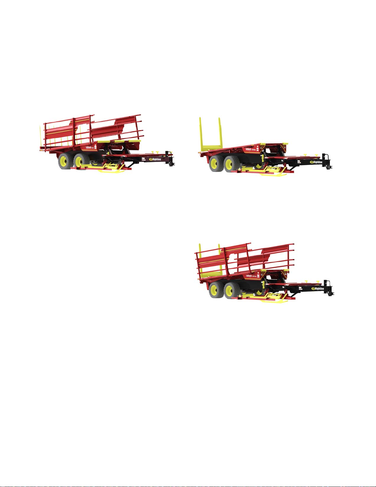
FaStack 1800 FaStack 1200 Flex
218067
218066
FaStack 1200 Flex with Optional Side
Racks
218068
Page 10
Section 1 - Safety
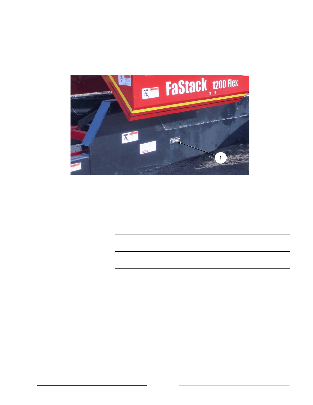
SERIAL NUMBER
Your serial number is found on the serial number plate (1) attached to the left hand side of
the main frame below the rear table of the FaStack.
Serial Plate Location
It is important to record the serial number for proof of ownership and for any service or
maintenance assistance.
219187C
Serial Number
Owner
Model
Date of Purchase
Page 1-1
Page 11

Section 1 - Safety
SAFETY SIGN-OFF FORM
Highline Manufacturing Ltd. follows the general Safety Standards specified by the American
Society of Agricultural Engineers (ASAE) and the Occupational Safety and Health Administration
(OSHA). Anyone who will be operating and/or maintaining the Highline FaStack should read and
clearly understand all Safety, Operating and Maintenance information presented in this manual.
Do not operate or allow someone to operate this equipment until this information has been
reviewed. This information should be reviewed by all operator’s before the season start-up.
This sign-off sheet is provided for record keeping to indicate that the person working with the
equipment has read and understood the information in the Operator’s Manual and has been
instructed in the safe operation of the equipment.
Date Employee’s Signature Employer’s Signature
Page 1-2
Page 12
Section 1 - Safety
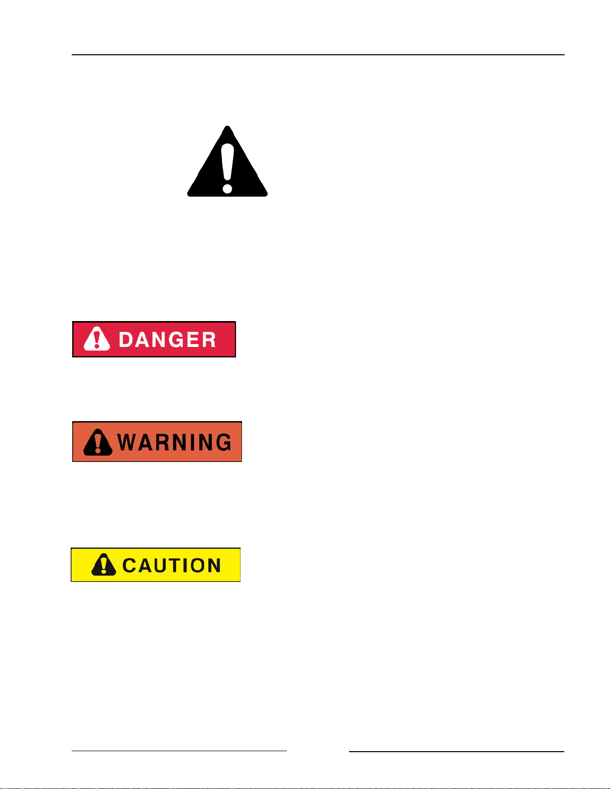
SAFETY ALERT SYMBOL
The Safety Alert Symbol means:
ATTENTION!
BECOME ALERT!
YOUR SAFETY IS INVOLVED!
The Safety Alert Symbol combined with a Signal Word alert to the presence of a hazard and the
degree of possible injury.
Indicates an imminently hazardous situation that, if not
avoided, WILL result in DEATH OR SERIOUS INJURY.
The color is Red with White lettering.
Indicates a potentially hazardous situation that, if not
avoided, COULD result in DEATH OR SERIOUS
INJURY, and includes hazards that are exposed when
guards are removed or unsafe practices. The color is
Orange with Black lettering.
Indicates a potentially hazardous situation that, if not
avoided, MAY result in MINOR INJURY. The color is
Yellow with Black lettering.
Page 1-3
Page 13

Section 1 - Safety
GENERAL SAFETY
1. Ensure that anyone who is going to operate, maintain or work near the FaStack is familiar
with the recommended operating, maintenance procedures and safety information contained
in this manual and follows all the safety precautions.
2. In addition to the design and configuration of the equipment, hazard control and accident
prevention are dependant upon the awareness, concern, prudence and proper training of
personnel involved in the operation, transport, maintenance and storage of the FaStack.
3. The FaStack shall not be operated without all the guards in place.
SAFETY DECALS
1. Keep decals and signs clean and legible at all times.
2. Replace decals and signs that are damaged, missing or have become illegible.
3. Replaced parts that displayed a decal should also display the current decal.
4. Decals are available from the Highline Parts Department.
5. Be familiar with the decals, the type of warning and the area or function(s) related to the
area(s) that requires your awareness.
Page 1-4
Page 14
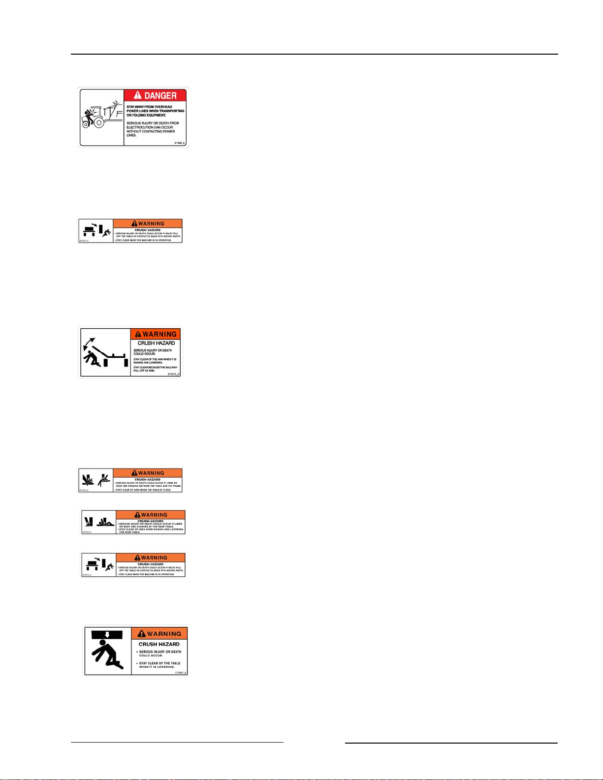
Section 1 - Safety
STAY AWAY FROM OVERHEAD POWER LINES
Stay away from power lines when transporting or folding
equipment.
Electrocution can occur without contacting power lines.
Contact with power lines will result in serious injury or death.
KEEP PEOPLE BACK WHEN LOADING BALES
Stay clear when loading bales which could fall.
Stay clear of machine when in operation.
Crushing could cause serious injury or death.
STAND CLEAR OF THE BALE LIFT ARM
Moving lift arm can cause serious injury or death.
Never stand under lift arms when lowering or raising.
Do not allow people near the lift arms when being moved.
Lift arms must be fully retracted and locked in place before
servicing.
Crushing could cause serious injury or death.
STAY CLEAR OF REAR TABLE WHEN RAISING OR
LOWERING
There is a crushing hazard if limbs or body is placed between the
table and ground or surrounding objects when the table is raised or
lowered.
Stay clear when unloading bales which could fall.
Stay clear of the table when it is lowering.
Crushing could cause serious injury or death.
Page 1-5
Page 15

Section 1 - Safety
STAY CLEAR OF FRONT TABLE WHEN IT IS TILTED
There is a crushing hazard if limbs or body is placed between the
front and rear table.
Stay clear of area when the front table is tilted.
Stay clear when front table is lifted because bales could fall.
Stay clear of the table when it is lowering.
Crushing could cause serious injury or death.
STAY CLEAR OF AREA WHEN TROLLEY IS MOVING
There is a crushing hazard if limbs or body is placed between the
trolley and side panels.
Crushing could cause serious injury or death.
STAND CLEAR OF ROTATING FRONT TABLE
(FaStack Flex 1200 Only)
Stand clear of front table when rotating. Front table can rotate
rapidly.
Contact with rotating table could cause serious injury or death.
UPENDING HAZARD
The hitch can rise rapidly when there are bales are being unloaded
for stacking.
Use the clevis that is attached to the machine.
Ensure implement is attached to machine before hydraulics are
activated.
Contact with the hitch could cause serious injury or death.
Page 1-6
Page 16
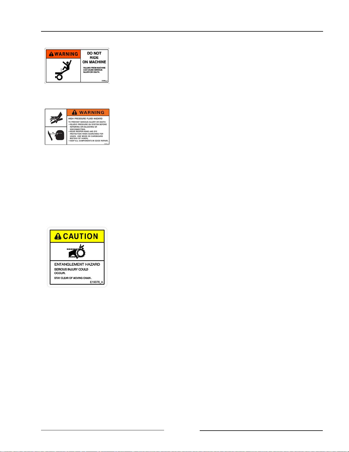
Section 1 - Safety
DO NOT RIDE ON MACHINE
Falling from the moving machine can cause serious injury or
death.
Falling from the operating machine could cause being entangled
under the machine or being injured by the machine.
USE PAPER OR CARDBOARD TO CHECK FOR HYDRAULIC
LEAKS
To prevent serious injury or death:
Relieve pressure on hydraulic system before repairing, adjusting or
disconnecting.
Wear proper hand and eye protection when searching for leaks.
Use wood or cardboard instead of hands.
Keep all components in good repair.
Fluid injected under the skin must be removed immediately by a
surgeon familiar with this type of injury.
DO NOT CONTACT MOVING CHAIN
Contacting moving chain or parts on the rear table may cause serious
injury or death.
Never attempt to manually remove bales while hydraulic cylinder is
moving the trolley/chain.
Always shut off tractor, remove key, set park brake and wait for all
parts to stop moving before servicing.
Page 1-7
Page 17
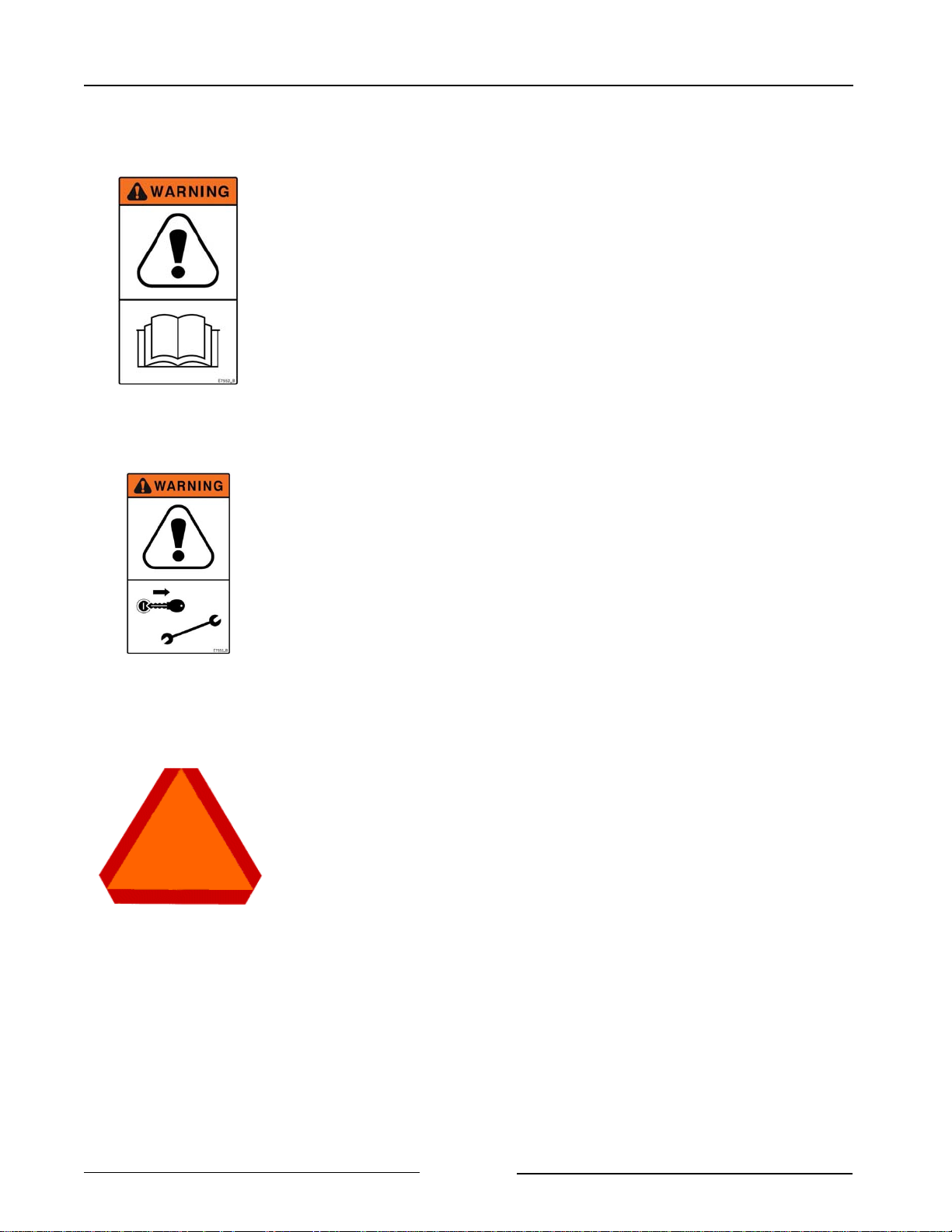
Section 1 - Safety
READ, UNDERSTAND, AND FOLLOW SAFETY INSTRUCTIONS
Read, understand and follow all instructions and safety messages
included in this manual and on decals attached to the machine.
Allow only responsible, properly instructed individuals to operate
and service the machine.
Failure to follow the instructions and safety messages in this
manual and on the decals attached to the machine could result in
serious injury or death.
Keep all safety and instruction decals in good condition. Replace
any missing or damaged decals.
STOP TRACTOR BEFORE GOING NEAR MACHINE
Always shut off tractor, remove key, set park brake and wait for all
parts to stop turning before servicing.
Turn off the control box if it is connected to tractor power that is
always on.
Failure to stop the tractor and wait for all moving parts to stop could
result in serious injury or death.
ENSURE SLOW MOVING VEHICLE SIGN IS IN PLACE
Ensure the Slow Moving Vehicle sign is in place, clean and easily
visible.
Ensure the reflectors are in place, clean and easily visible.
Page 1-8
Page 18
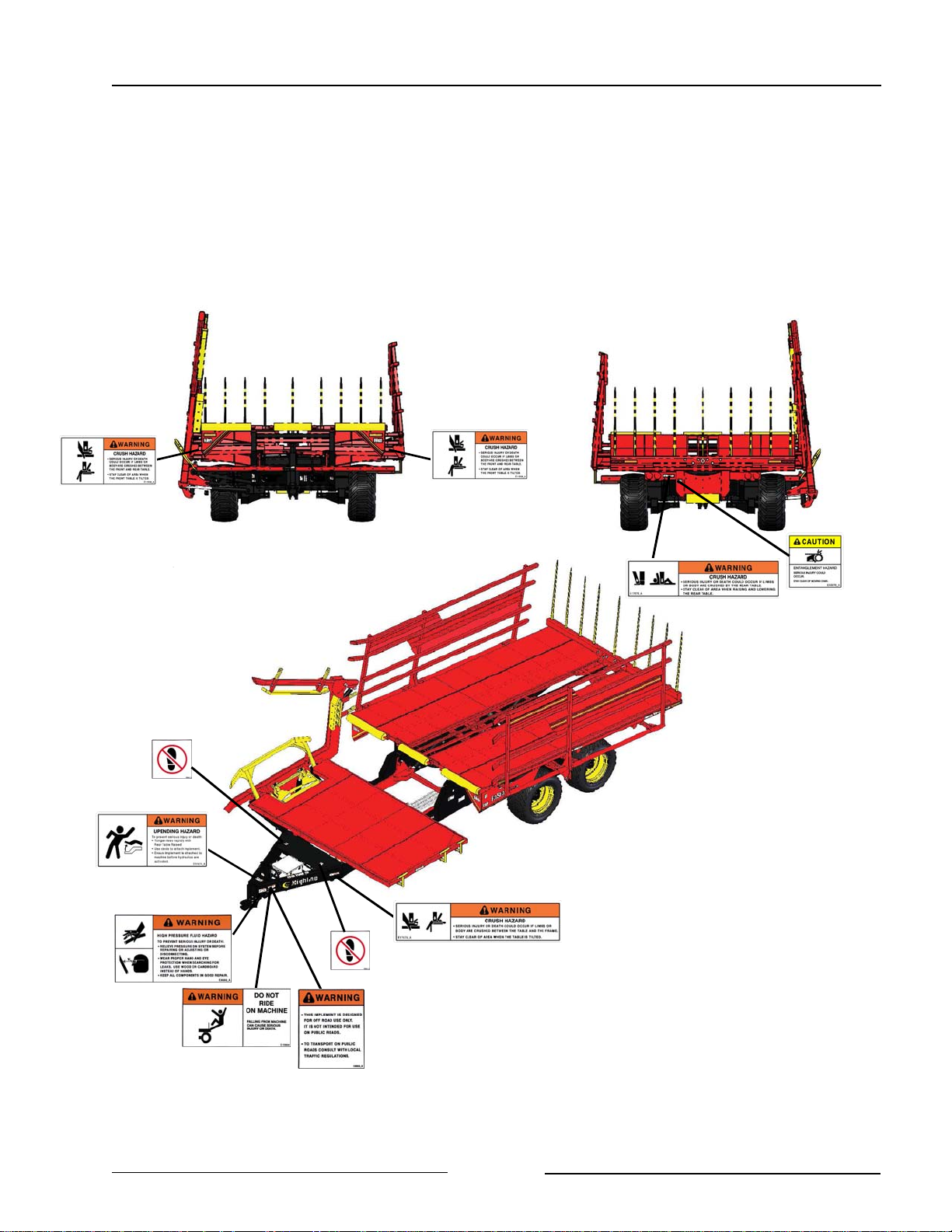
Section 1 - Safety
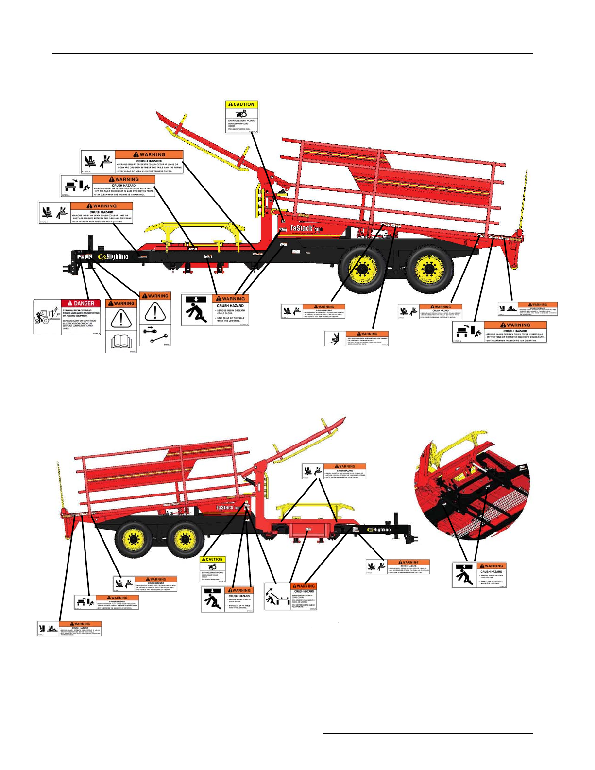
SAFETY DECAL LOCATIONS - FaStack 1800 - 1 of 2
Page 1-9
44076_A1
Page 19
Section 1 - Safety
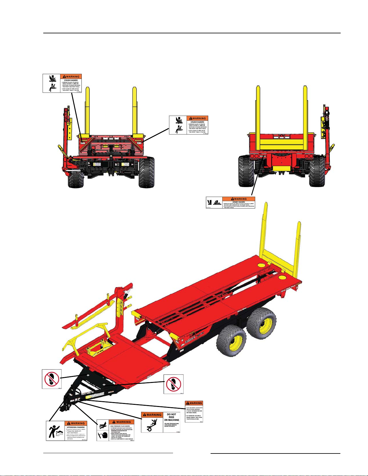
SAFETY DECAL LOCATIONS FaStack 1800 - 2 of 2
44076_A2
Page 1-10
44076_A3
Page 20
Section 1 - Safety
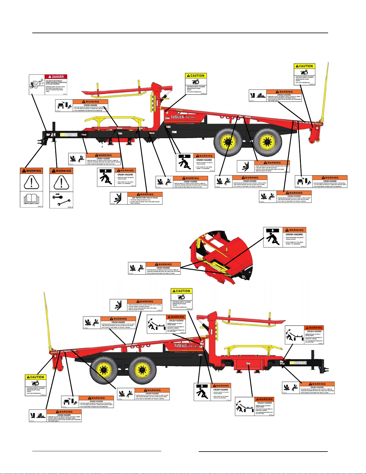
SAFETY DECAL LOCATIONS - FaStack 1200 Flex - 1 of 2
Page 1-11
44201_A1
Page 21
Section 1 - Safety
SAFETY DECAL LOCATIONS - FaStack 1200 Flex - 2 of 2
Page 1-12
Page 22
Section 2 - FaStack Display and Joystick
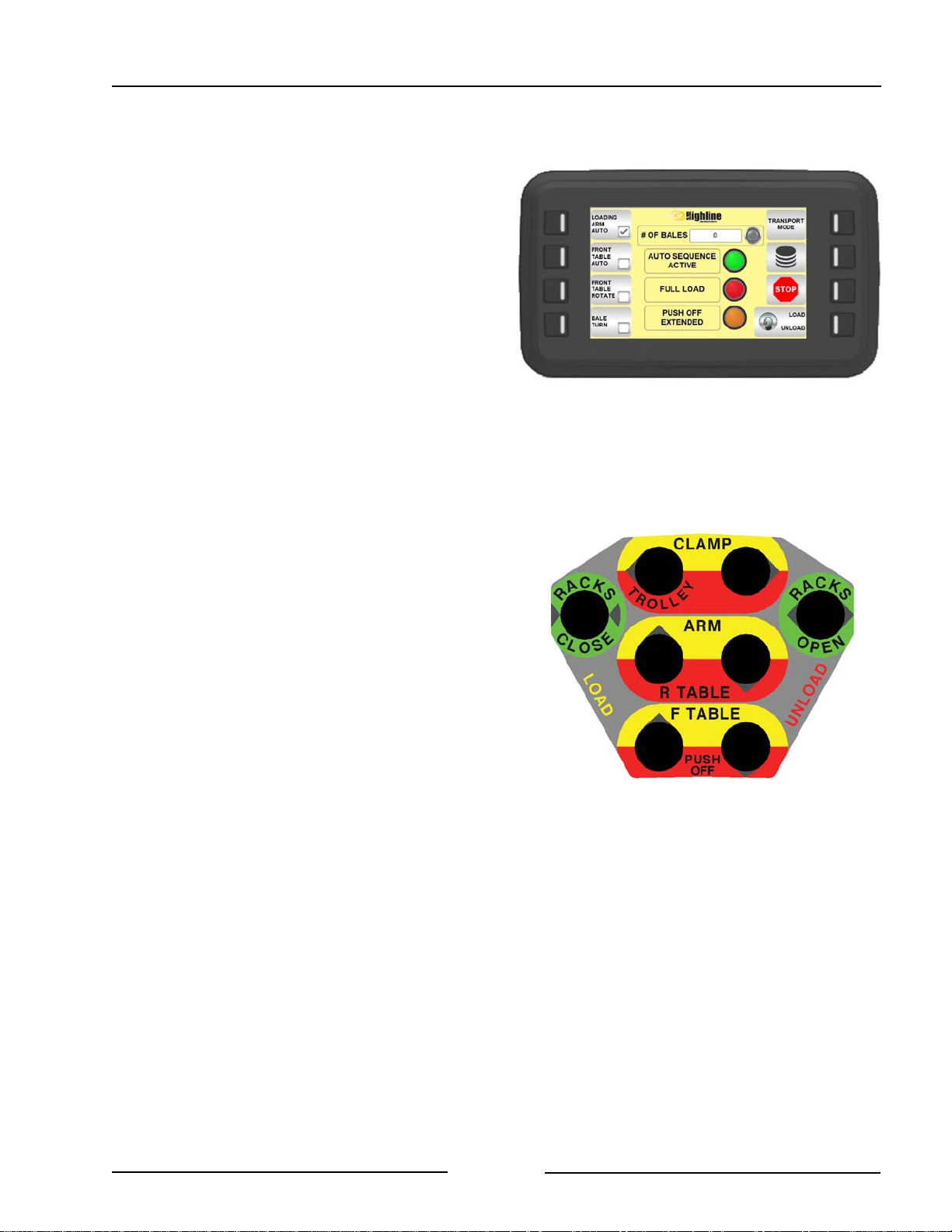
FaStack Display
The FaStack display is used in the cab for
making operation choices and viewing the
status/operation of the machine.
The display is a touch screen but also has
buttons on the side that can be used for
making screen choices.
There is a home page and a menu for
choosing additional screens. In the other
screens the user can adjust settings, find
operation information and view the status of
sensors.
FaStack Display - Main Page
219162
Joystick
The FaStack uses a joystick which the
operator uses in the cab. The joystick
controls loading and unloading operations.
The joystick buttons are color coded for dual
function.
Load = Yellow
When the Load mode is selected on the
display, the joystick buttons will control the
item in the yellow color.
Unload = Red
When the Unload mode is selected on the
display, the joystick buttons will control the
item in the red color.
The grey arrows on the side of the button
indicate the direction of operation.
Joystick Control
E15884_A
Some operations of the FaStack can be done
in an "Automatic" mode in which preset
operation sequences are chosen on the
display and activated on the joystick with a
push of a single button.
Page 2 -1
Page 23
Section 2 - FaStack Display and Joystick
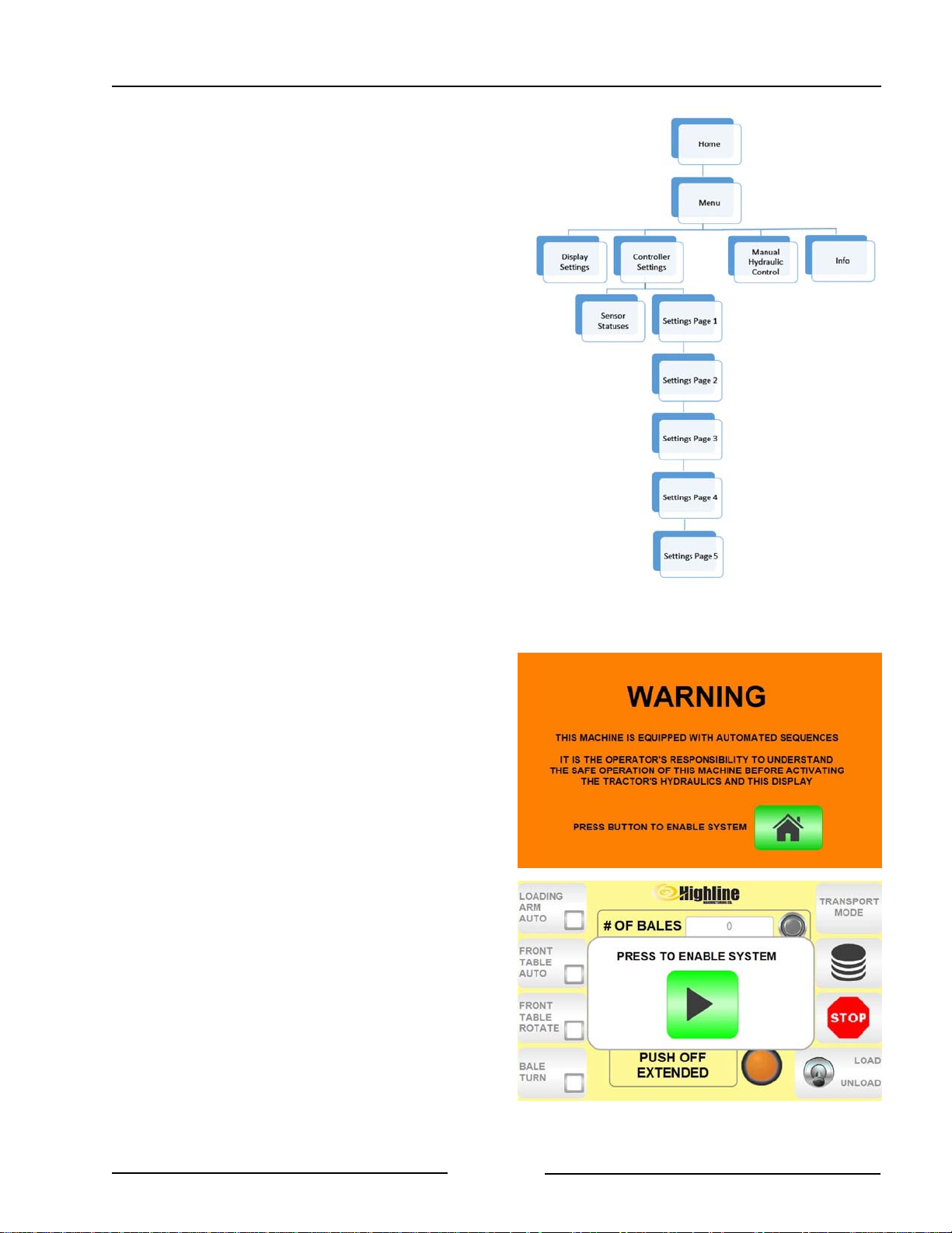
Software Menu Tree
The software is designed to show a number
of display screens. The screens offer
operational choices and also the option to
advance to additional screens.
The software menu tree is a visual
representation of the display screens.
This menu tree can be used a reference to
navigate to the various screens.
The information given below gives further
information about each screen and the
choices made on that screen.
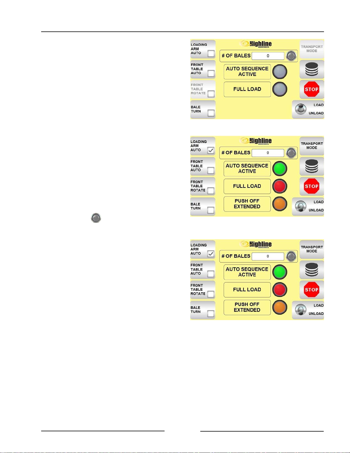
Startup of the Display
When the display starts up it shows a
WARNING screen.
Read the Warning carefully about the
Operator's responsibility to understand the
automated sequences and the safe operation
on the machine before activating the
hydraulics and enabling the display.
Press the green HOME button to enable the
control system.
A second screen will appear requiring the
pushing of the Green Arrow button to enable
the system.
Software Menu Tree
219028
Press to Enable System
Page 2 -2
219167
Page 24
Section 2 - FaStack Display and Joystick
Home Screen for 1800 and 1200 Flex
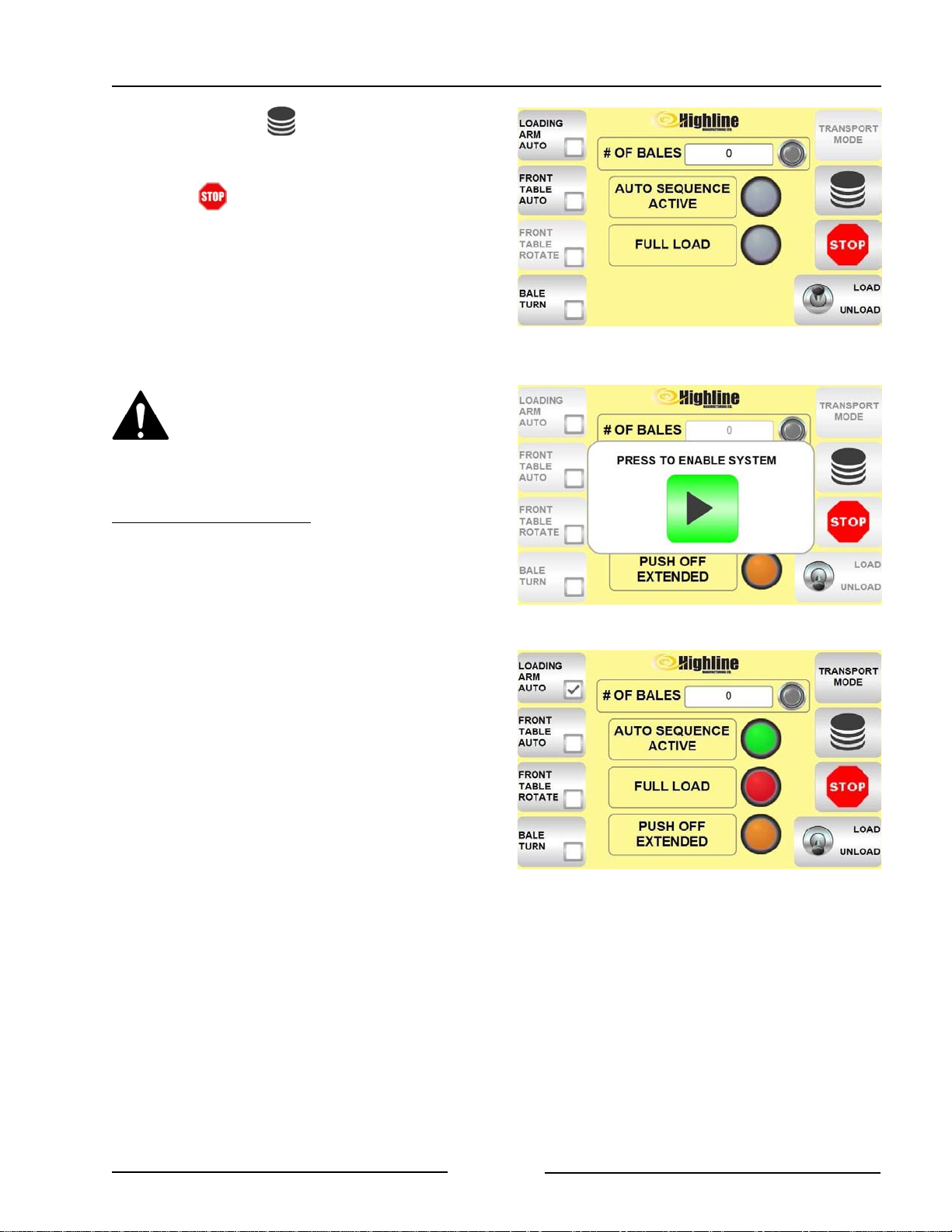
The software in the controller is set for the
model of FaStack it is installed on.
The Home Screen will show the functions
available based on the machine.
When a button is active the box inside the
button will have a check mark.
The Home Screen for the 1200 Flex will
additional information regarding the front
table rotate and the push off cylinders.
When a button is active the box inside the
button will have a check mark.
The # OF BALES is a counter that can be
reset for indicating the daily bale count day or
field count.
- Pressing will reset the counter to
zero.
TRANSPORT MODE is used to move the
loading arm to the raised position.
- This button is used when the table is
full and the machine is ready for
transporting to the unloading site.
FaStack 1800 Home Screen
FaStack 1200 Flex Home Screen
219164
219163
- No joystick button press is needed to
activate this mode.
- Loading Arm Auto needs to be
checked.
- Press the Transport Mode button
on the display to activate it..
- The TRANSPORT MODE button will
flash red while the loading arm is up.
- To lower the arm from the
TRANSPORT MODE press the
button. The arm will move down to the
ready position.
Page 2 -3
FaStack 1200 Flex Home Screen
219163
Page 25
Section 2 - FaStack Display and Joystick
The menu button opens a display of
options with additional options under it.
Pressing will stop any signal to a
hydraulic valve and therefore stop the
operation in progress.
- A pop-up message will come up on
the display indicating that the operator
will need to press an Enable System
button to reactivate the outputs.
Only press the ENABLE SYSTEM
button when all persons are away
from the machine and moving
parts.
FaStack 1800 Home Screen
218199
For 1800 and 1200 Flex
The loading arm can be manually controlled
with the joystick buttons.
LOADING ARM AUTO is the option to have
the bale loading arm sequence automated
through a single button push on the joystick
once the bale is positioned into the loading
arm.
- Pushing the button ARM up joystick
will automate the following:
- Close the clamp arm.
- Position the bale according to the
bale turn selection.
- Lift the arm.
- Place the bale onto the front table.
- Lower the loading arm to the ready
position.
- Open the clamp for the next bale.
Reactivate System after Pushing Stop
FaStack 1200 Flex Home Screen
219167
219163
Note: Loading Arm Auto needs to be
checked for the Transport Mode
button to work.
See Section 5 for Operational Information
on using the Loading Arm Auto.
Page 2 -4
Page 26
Section 2 - FaStack Display and Joystick
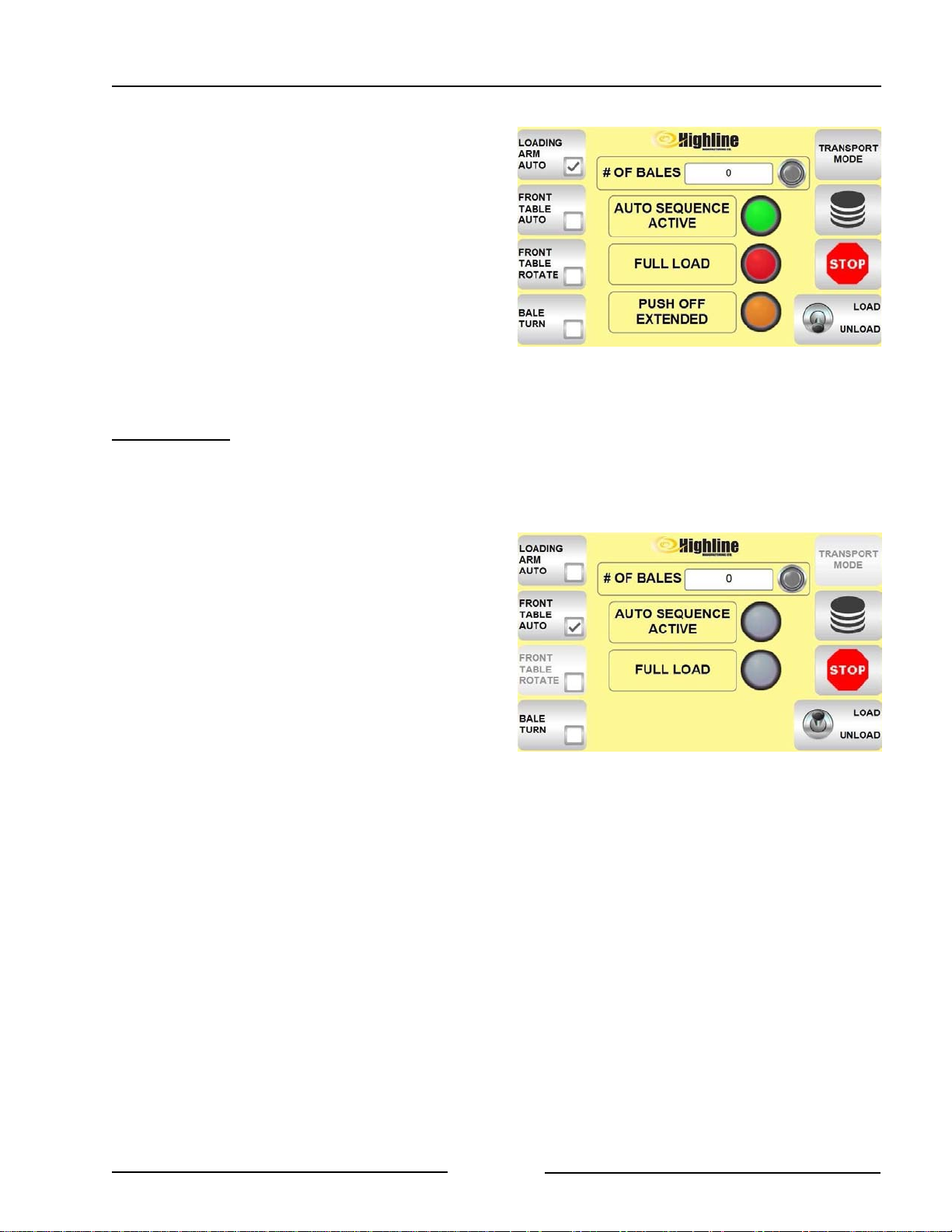
AUTO SEQUENCE ACTIVE
Any time the LOADING ARM AUTO or the
FRONT TABLE AUTO has been activated
the AUTO SEQUENCE ACTIVE green light
will come on to indicate that a sequence is in
process.
- Once the automated sequence is
complete the light will go out.
For 1800 Only
The front table can be controlled manually
with the joystick buttons.
FRONT TABLE AUTO is the option to have
the front table rising to place the bales onto
the rear table and the front table lowering
automated with a single button push.
- The push of the joystick button Front
Table Up will start the following:
- Check if the loading arm is
lowered out of the way.
- Open the side racks.
- Raise the front table to move bales
onto the rear table.
- Close the side racks.
- Lower the front table.
FaStack 1200 Flex Home Screen
FaStack 1800 Front Auto Table
219163
219164-1
See Section 5 for Operational Information
on using Front Table Auto.
Page 2 -5
Page 27
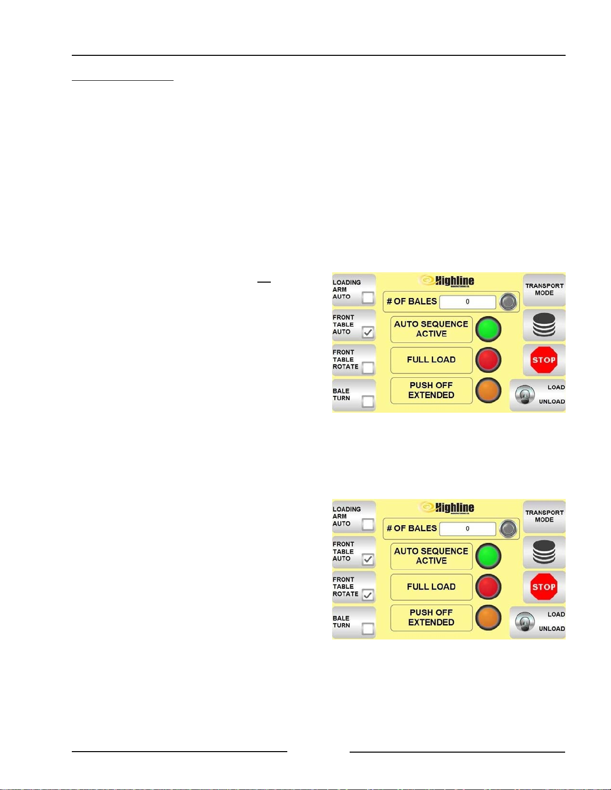
Section 2 - FaStack Display and Joystick
For 1200 Flex Only
The front table can be controlled manually
with the joystick buttons.
The FRONT TABLE AUTO is the option to
have the front table rising to place the bales
onto the rear table and the table lowering
automated with a single button push.
FRONT TABLE AUTO sequence will depend
if the FRONT TABLE ROTATE option has
been selected.
! FRONT TABLE AUTO with no table
rotate
- The push of the joystick button Front
Table Up will start the following:
- Check if the loading arm is
lowered out of the way.
- Open side racks (if present).
- Raise the front table to move bales
onto the rear table.
- Close side racks (if present)
- Lower the front table.
FaStack 1200 - Front Table Auto
219163-1
See Section 5 on Operational Information on
using Front Table Auto with no table rotate.
! FRONT TABLE AUTO + FRONT TABLE
ROTATE
- The push of the joystick button Front
Table Up will start the following:
- Check if the loading arm is
lowered out of the way.
- Raise the front table about 8".
- Rotate the front table 90 degrees
- Raise the front table to move bales
onto the rear table.
- Lower the front table while also
rotating the front table back to the
bale loading position.
See Section 5 for Operational Information on
using Front Table Auto + Front Table Rotate.
FaStack 1200 - Front Table Auto + Front
Table Rotate
216163-2
Page 2 -6
Page 28
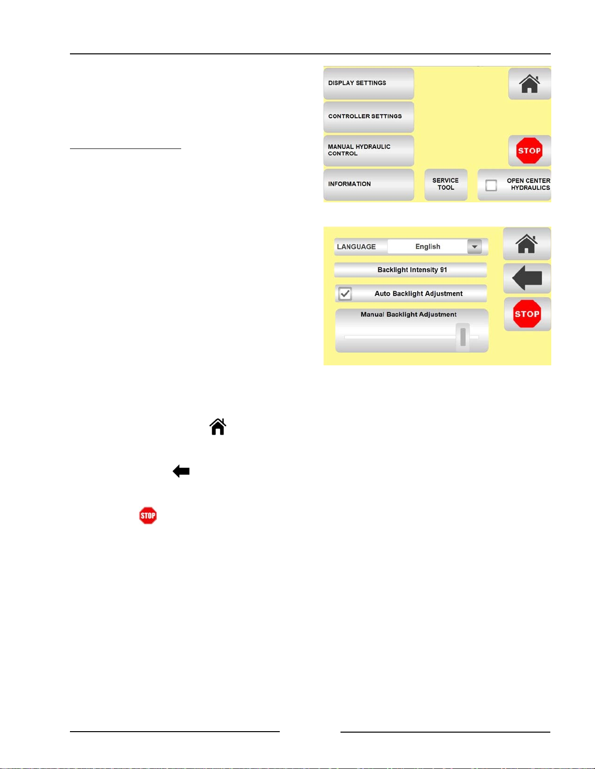
Section 2 - FaStack Display and Joystick
Menu Screen Selections
The Menu Screen gives a number of
selections.
DISPLAY SETTINGS
The Display Settings button allows:
- Select the Language for the display.
- Selection of Auto Backlight
Adjustment.
- This selection will increase/
decrease the screen brightness
depending on the amount of
ambient light present.
- Manual Adjustment of the backlight
intensity of the display.
- Remove the check mark from the
Auto Backlight Adjustment.
- Move the slider to the desired
backlight intensity
The Home Page button will return the
display to the Home Page.
The Back Button will return the display
to the Menu screen.
Menu Screen
Display Settings Page
219170
219171
Pressing will stop any signal to a
hydraulic valve and therefore stop the
operation in progress.
Page 2 -7
Page 29
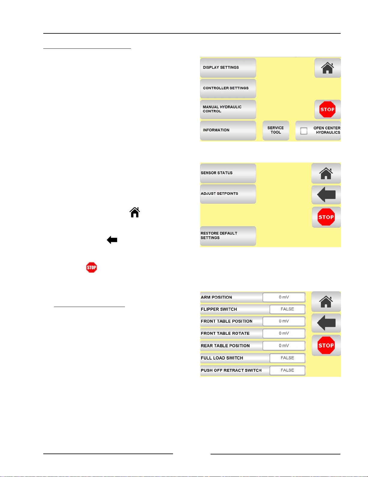
Section 2 - FaStack Display and Joystick
CONTROLLER SETTINGS
The Controller Settings button allows:
- Sensor Statuses button brings a
screen that shows the status of the
sensors.
- Adjust Setpoints button brings up
screens to adjust the set points of the
sensors.
- See the section "Adjust Set Points"
for more information.
- The Restore Default Settings buttons
restores the default settings to the
sensors.
- The Service Tool button is only to be
used with the assistance of the
Service Department. A pass code is
required for this diagnostic mode.
The Home Page button will return the
display to the Home Page.
- Rear Table Position
Menu Screen
219170
The Back Button will return the display
to the Menu screen.
Pressing will stop any signal to a
hydraulic valve and therefore stop the
operation in progress.
SENSOR STATUSES
The Sensor Status screen gives information
on the function of the rotary sensors (readout
in millivolts) and which switches are turned
on/off.
Note: Statuses will only show for the
model of FaStack. There are
additional statuses for the FaStack
1200.
" Display the output voltage of the:
- Arm Position
- Front Table Position
- Front Table Rotate (1200 only)
- Rear Table Position
Controller Settings Page
Sensor Status Page
(For FaStack 1200 shown)
219172
219173
Page 2 -8
Page 30
Section 2 - FaStack Display and Joystick
" Check if:
- Flipper Switch is showing TRUE or
FALSE
- Full Load Switch is showing TRUE
or FALSE
- Push Off Retract Switch is
showing TRUE or FALSE (1200
Flex only)
- If any of the sensors are not showing
voltage or TRUE or FALSE then
check the sensor and connections.
- Press the Home button to
return to the Home screen.
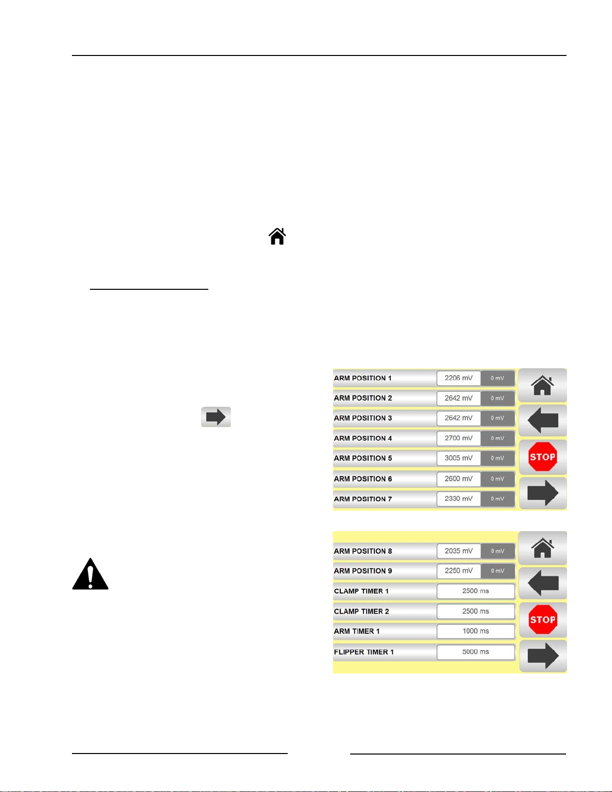
ADJUST SETPOINTS
The Setpoints determine the limits and action
points of the arm, clamp, tables and side
racks.
- The Setpoints are pre-set in the
software that is installed at the factory.
There are 5 pages of setpoints. To move to
the next page press the button
Note: Settings will only show for the
model of FaStack.
If wanting to make to make adjustments to
any of the setpoints because of the way the
bales are loading, the adjustments can be
made by selecting which value to change.
Be aware that adjusting these
values will modify the operation of
the machine. Ensure you have a
full understanding of the effect of
the changes. Contact Highline for
assistance.
Note: Descriptions of the setpoints are
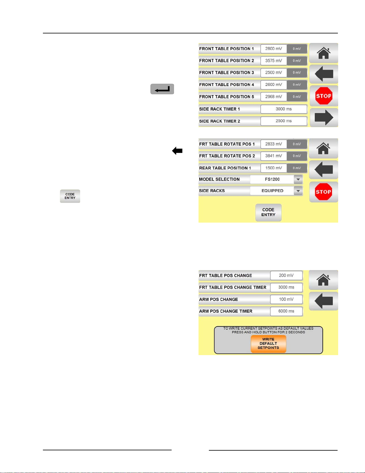
given in the table on page 2-11.
Settings Page 1
Settings Page 2
219174
219175
Page 2 -9
Page 31
Section 2 - FaStack Display and Joystick
- When a setting is tapped to make an
adjustment a calculator style keypad will
show on the display.
- Use the keypad to enter a new value.
- Press the enter button to
register the new setpoint value.
- The change will be retained when the
system is powered off.
The Default Settings for all the setpoints can
be restored by pressing the back button
until at the Controller Settings page and
tapping the RESTORE DEFAULT
SETTINGS.
Settings Page 3
(For FaStack 1200 shown)
219176
The is only used when a setting
change is desired to be written as the new
default. The change will over-write the
previous default setting.
- A password code is required to overwrite the default settings. Contact
Highline for assistance.
Once the pass code is entered a new page
will come up showing the settings changes.
- The option to write WRITE DEFAULT
SETPOINTS is given.
Note: Once the changes have been
written as the new default
setpoints it is not possible to go
back to the factory defaults without
further Service assistance from
Highline.
Settings Page 4
Settings Page 5 - Over Write Defaults
(For FaStack 1200 Shown)
219025
219178
Page 2 -10
Page 32

Section 2 - FaStack Display and Joystick
Adjust Setpoint Descriptions
Adjust Setpoint Sensor Description
ARM POSITION 1 Arm rotary sensor Position at which the flipper up starts
activating during the arm raise cycle with
bale turn off.
ARM POSITION 2 Arm rotary sensor Position at which the arm stops prior to
lowering quickly in the "stutter step" of the
arm lift cycle.
ARM POSITION 3 Arm rotary sensor Position to which the arm lower to during
the stutter step during the arm raise cycle
with bale turn off.
ARM POSITION 4 Arm rotary sensor Position at which the flipper continues
during the arm raise cycle with bale turn off.
ARM POSITION 5 Arm rotary sensor Arm upper limit.
ARM POSITION 6 Arm rotary sensor Position at which the flipper down starts
activating during the arm lower cycle with
bale turn off.
ARM POSITION 7 Arm rotary sensor Position at which the flipper must have
reached the flipper position proximity
sensor during the arm lower cycle with bale
turn off.
ARM POSITION 8 Arm rotary sensor Arm lower limit.
ARM POSITION 9 Arm rotary sensor Position below which the front table is
allowed to raise and lower and rotate.
CLAMP TIMER 1 Time that the clamp closes during the
automated arm raise cycle.
CLAMP TIMER 2 Time that the clamp opens during the
automated arm raise cycle.
ARM TIMER 1 Time that the arm pauses at the top end of
the loading cycle
FLIPPER TIMER 1 Time that the flipper continues to lower after
the arm had reached the lower limit to
ensure the flipper is all the way down.
FRONT TABLE
POSITION 1
Front table
up/down rotary
Position at which the side racks open to
accept the next row of bales.
sensor
Page 2 -11
Page 33

Section 2 - FaStack Display and Joystick
FRONT TABLE
POSITION 2
Front table
up/down rotary
Upper limit of front table.
sensor
FRONT TABLE
POSITION 3
Front table
up/down rotary
Lower limit of front table.
sensor
FRONT TABLE
POSITION 4
(FaStack 1200 only)
Front table
up/down rotary
sensor
Position at which the front table starts
rotating in the raise cycle. Also position at
which the front table cannot be lowered
past if the front table is not rotated to its
home position.
FRONT TABLE
POSITION 5
(FaStack 1200 only)
Front table
up/down rotary
sensor
Front table position at which the front table
starts rotating in the lower cycle.
SIDE RACK TIMER 1 Time that the side racks open during the
automated front table raise cycle.
SIDE RACK TIMER 2 Time that the side racks close during the
automated front table raise cycle.
FRONT TABLE
ROTATE POSITION 1
Front table rotate
rotary sensor
Front table home position.
(FaStack 1200 only)
FRONT TABLE
ROTATE POSITION 2
Front table rotate
rotary sensor
Front table fully rotated position.
(FaStack 1200 only)
REAR TABLE
POSITION 1
(FaStack 1200 only)
Rear table
up/down rotary
sensor
Position above which the extension of the
push off cylinders is allowed.
MODEL SELECTION Which model of FaStack the display is
connected to.
SIDE RACKS If side racks are
installed the
This option is only available on the FaStack
1200.
machine.
Page 2 -12
Page 34
Section 2 - FaStack Display and Joystick
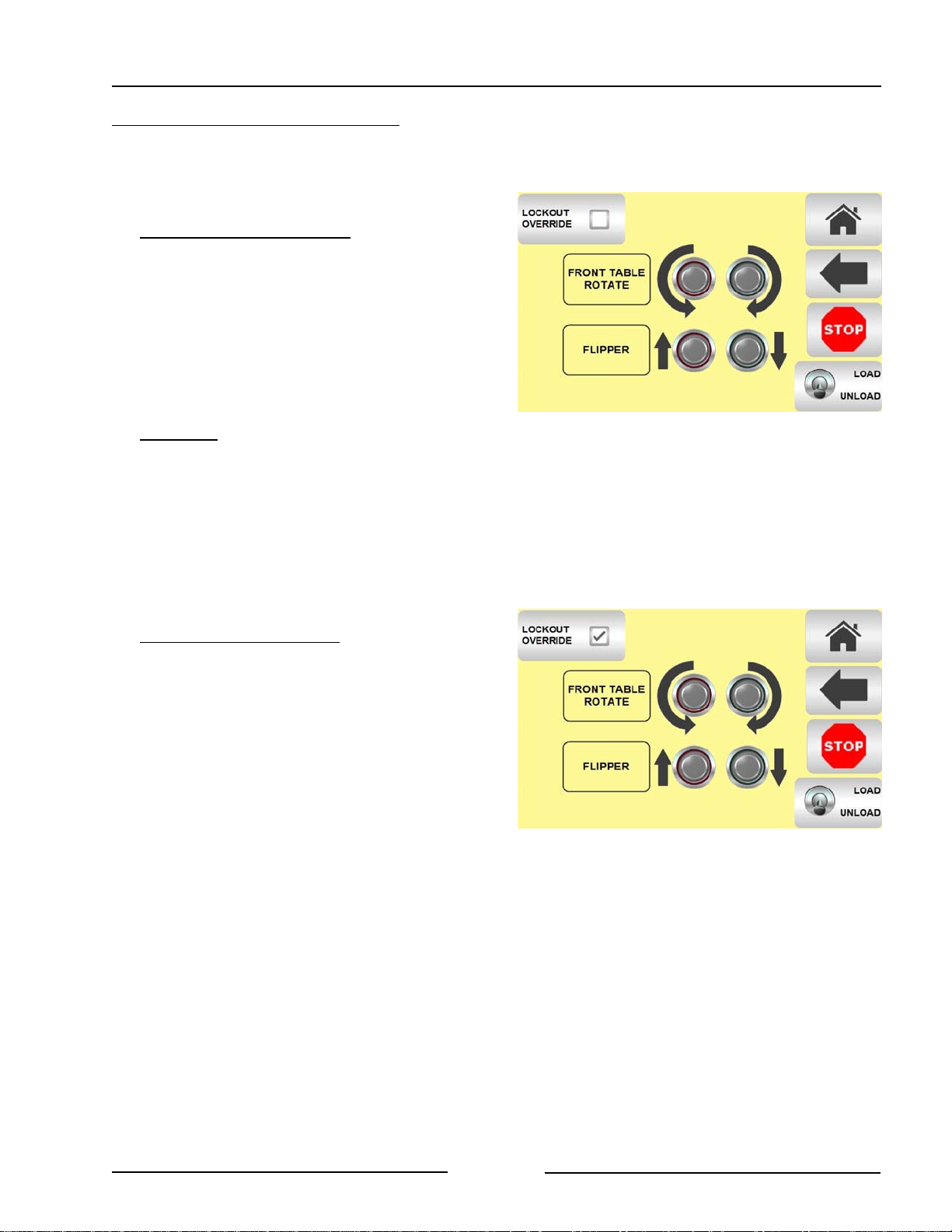
MANUAL HYDRAULIC CONTROL
Manual Hydraulic Controls are used when
there is a sensor failure or some other
unanticipated event.
FRONT TABLE ROTATE
The Manual Hydraulic Control allows for
manual rotation of the front table on the
FaStack 1200.
- The buttons on the display show the
direction of table rotation. Pushing the
button activates the hydraulic valve
and moves the table.
FLIPPER
The Manual Hydraulic Control allows for
manual movement of the flipper on the
loading arm on the both models.
- The buttons on the display show the
direction of flipper movement. Pushing
the button activates the hydraulic
valve and moves the flipper.
LOCKOUT OVER-RIDE (Rarely used)
When the Lockout Over-Ride is activated,
all the buttons on the joystick operate
their respective functions without regard
of the lockout conditions that are
programmed in the software. The
Lockouts are used to prevent machine
damage from machine parts contacting
other parts.
Manual Hydraulic Control Screen
Lockout Over-Ride
219179
219179-1
Note: Caution must be used in the Lockout
Over-Ride function as it is possible to
cause machine damage.
- The software has lockouts to prevent
parts of the machine from interfering
with the movement of other parts.
- When Lockout Over-Ride is activated
software that prevents machine
damage are turned off.
- Parts of the machine could be
moved into the path of other parts
of the machine causing damage.
Page 2 -13
Page 35
Section 2 - FaStack Display and Joystick
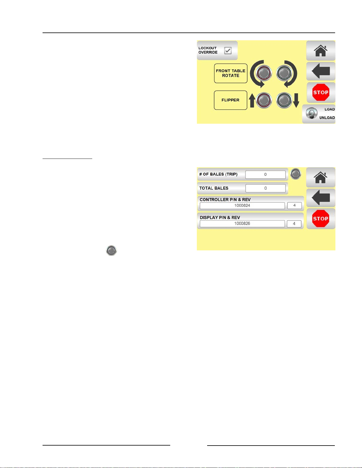
When the Lockout Over-Ride is activated
the Loading Arm Automation, the Front
Table Automation, and the Front Table
Rotate are turned off as well.
The Lockout is toggled with the button on
the display.
- When tapped the user must select
Yes or No before it turns on.
Deactivating can be done instantly
with a button push.
INFORMATION
The Information Screen provides information
the number of bales picked and the version
of the software in the controller and the
display.
Lockout Over-Ride
219179-1
# OF BALES (TRIP) is a resettable counter
for the bales stacked in a field or over a time
period. The resettable counter is the same as
the counter on the Home page of the display.
- Pressing the button will reset the
counter to zero.
TOTAL BALES gives the count of the bales
stacked since the machine was
manufactured.
CONTROLLER P/N AND REV gives the
information on the machine mounted
controller.
DISPLAY P/N AND REV gives the
information on the display.
Information Screen
219180
Page 2 -14
Page 36
Section 3 - Transporting the Bale Stacker
3.0 Transporting the Bale Stacker
Only tow the Bale Stacker behind
a properly sized and equipped
tractor or vehicle which exceeds
2/3 (66%) of the loaded stacker
weight.
Shut off the tractor engine before
attaching the bale stacker or
hydraulics.
Do not allow children or other
people to ride on the tractor or
bale stacker. Falling off can result
in serious injury or death.
1. Tractor requirements.
- Roll Over Protection System (ROPS)
- Working seatbelts
- 1 Spool Control Valve (SCV)
- 12 volt power
Note: See Section 5 for a chart
indicating the category of
tractor hitch required based on
the weight of the bales being
loaded.
Lift the Hitch
219032
Note: It is the operator's responsibility to
ensure the appropriate tractor is used that
can handle the vertical hitch loads as
listed.
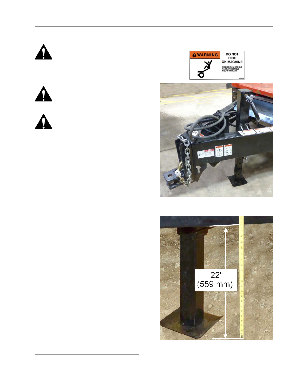
2. Lift the hitch.
- Lift the hitch with the jack.
- Do not attempt to lift the hitch
without using the jack.
- Lift the hitch until the frame is 22" (559
mm) off the ground.
Note: This frame height is important in
order for the bale clamp to operate
properly. If the frame is too low,
the clamp contacts the ground and
damage can occur.
Page 3-1
Frame at 22" (559 mm)
219031C
Page 37
Section 3 - Transporting the Bale Stacker
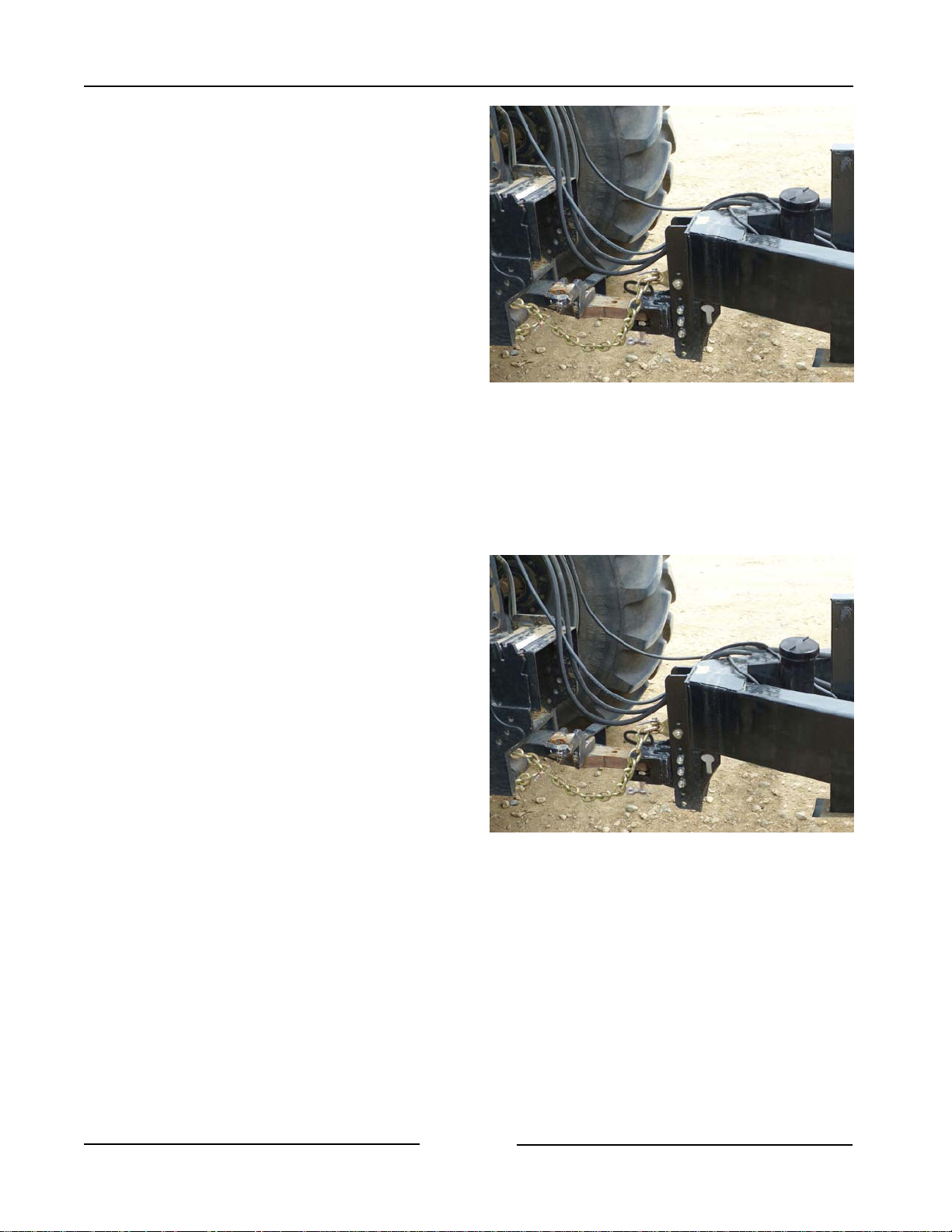
3. Adjust the position of the hitch clevis.
- Remove the clevis bolts (1) and move
the clevis so that the bale stacker can
connect to the tractor drawbar while
maintaining the bale stacker frame
height of 22" (559 mm) off the ground.
- Fasten in the clevis in place. Torque
to 260 ft-lb (353 Nm) dry.
4. Connect the hitch to the tractor drawbar.
- Use at least a 1-1/4" (31.75 mm) pin.
5. Connect the safety chain to the tractor
and fasten securely.
Adjust Clevis. Connect Hitch and Safety Chain
219033
6. Place the hitch jack in the storage
position.
- Remove all weight from the jack.
- Raise the jack foot by pulling on the
lock pin and raising the foot to the
highest position.
- Fasten the foot in place with the
lock pin.
7. Tractor tire width settings.
- When working on inclines or rough
ground, use the largest tractor wheel
width possible to maintain tractor
stability.
Place Jack in the Storage Position
219033
Page 3-2
Page 38
Section 3 - Transporting the Bale Stacker
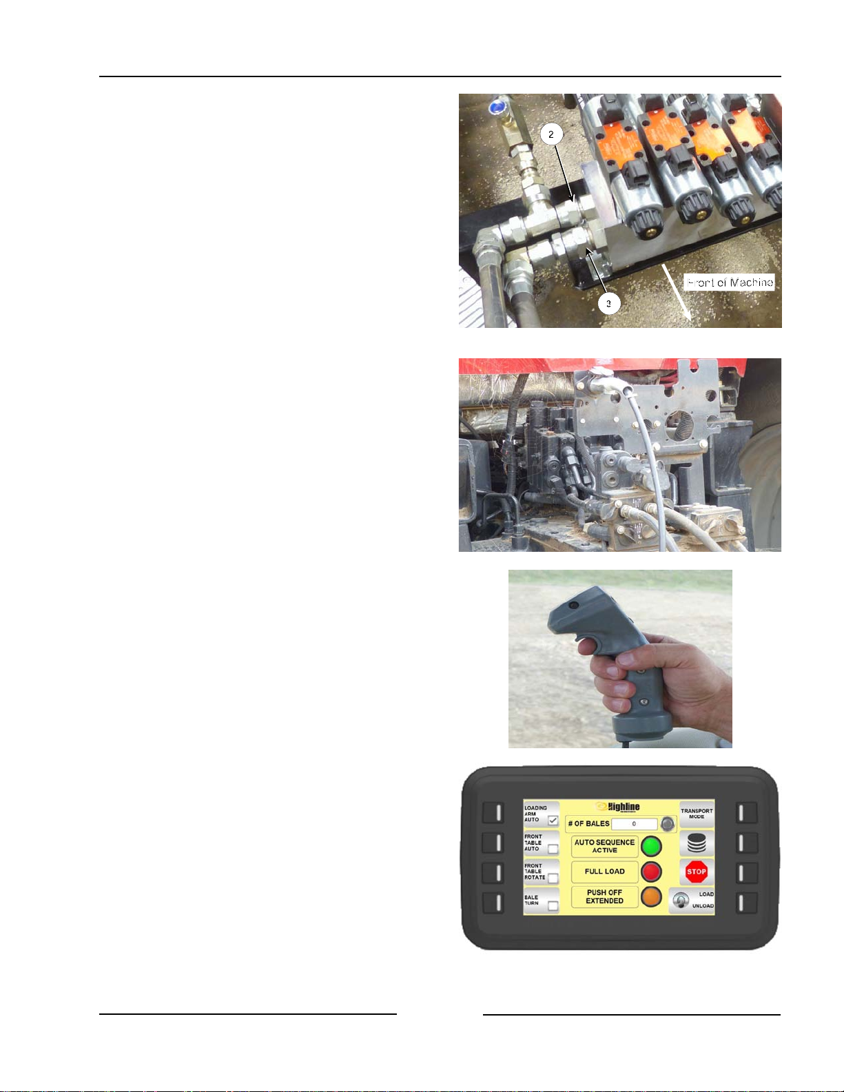
8. Attach the hydraulic hoses.
- Clean the end of the hoses and the
connection.
- The pressure hose from the tractor
must plug into the port of the hydraulic
block marked with "P" on the block
(2).
- The return hose from the tractor
must plug into the port of the
hydraulic block marked with "T" on
the block (3).
- Firmly push the hoses into the tractor
receptacle.
Hoses on the Valve Block
219056C
- Route the hoses so they do not
interfere with moving parts.
9. Connect the lighting cable to the electrical
connection on the tractor.
10. Route the cab harness to the hitch
harness of the stacker.
- Connect to the harness on the
hitch harness of the stacker.
- Ensure the cable does not
interfere with or contact moving
parts.
11. Place the joystick and display in the
tractor cab.
- Mount the display and joystick
holder using the supplied suction
cup mount.
Attach Hydraulics
Joystick
217084-1
Page 3-3
FaStack Display
(Joystick Holder not shown)
219162
Page 39
Section 3 - Transporting the Bale Stacker
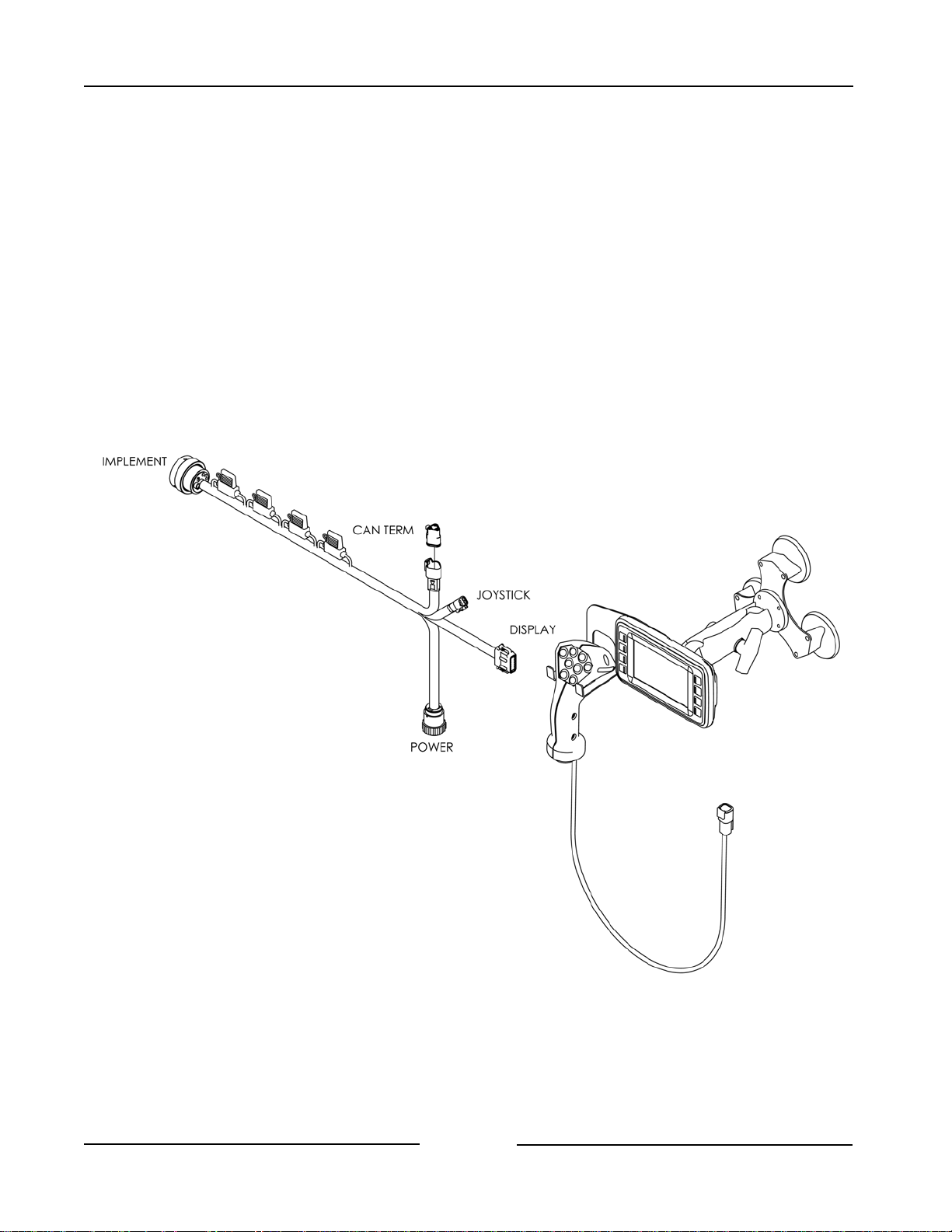
12. Connect the joystick to the harness
connection.
13. Connect the display to the harness
connection.
14. Connect the power cord into the key
and constant 12V DC power supply of
the tractor.
- Connect the round connector
power connector into the tractor
power receptacle.
Cab Harness, Power, Display and Joystick Connections
Page 3-4
43543_B
Page 40
Section 3 - Transporting the Bale Stacker
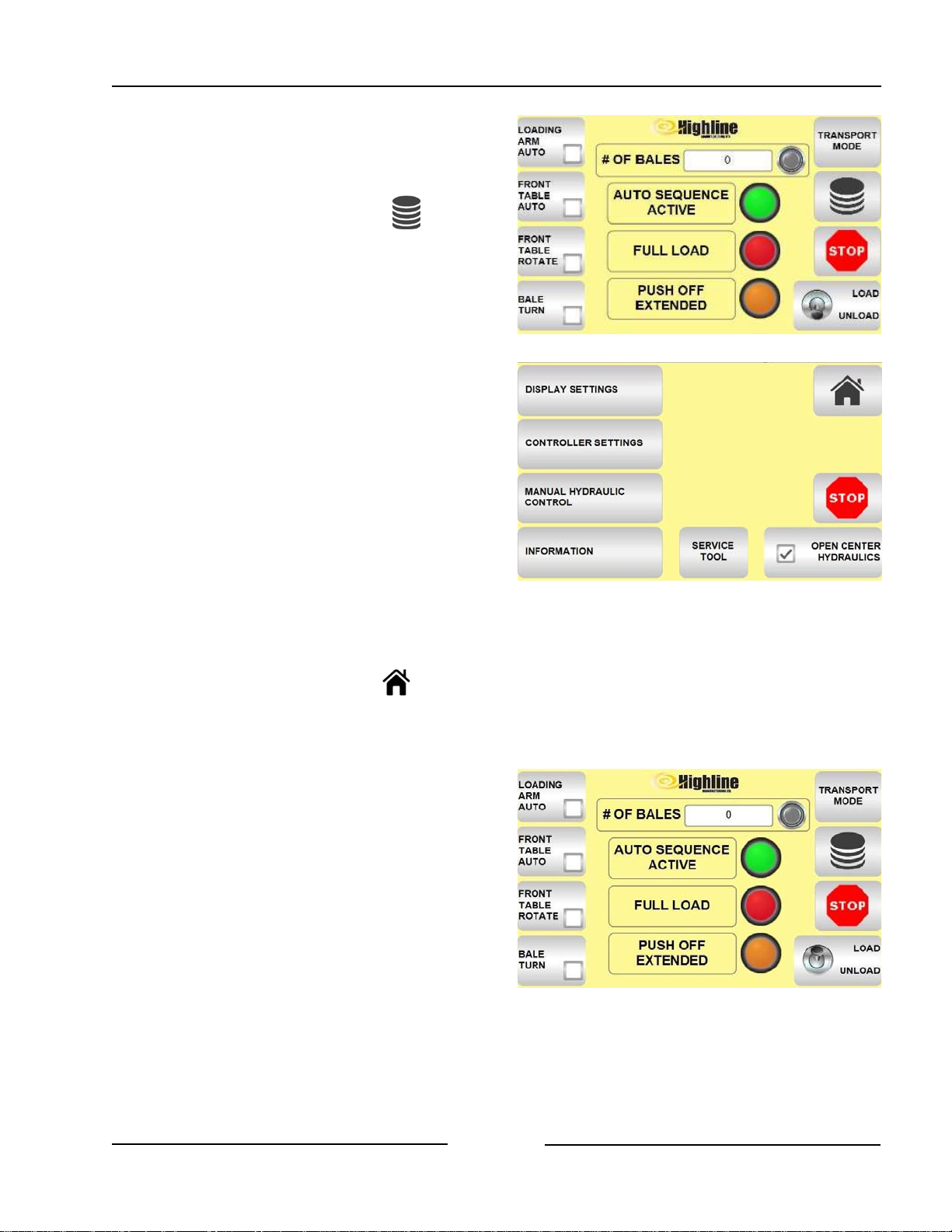
15. If needed, select for Open Center
Hydraulics.
- To select Open Center hydraulics
• Touch the Menu button on the
display home screen.
• Touch Open Center Hydraulics.
- There should be a check mark
in the small box to indicate it is
turned on.
Note: If changing between open and
closed center tractors then
some of the hydraulic flow
valves will need to be adjusted
because of the way the
different hydraulic systems
operate. See Section 4 for
valve adjustment details.
Display Home Screen
219181
15. Press the Home button on the
display to go back to the Home
Screen.
16. Touch the Load button on the Home
Screen to turn on the loading
functions of the machine and joystick
buttons.
- The toggle switch should be up to
indicate it is turned to load mode.
Note: Touching the button a second
time will toggle to the Unload
mode.
Select Open Center Hydraulics - Menu Screen
Turn on the Load Function
219170-1
219163-3
Page 3-5
Page 41
Section 3 - Transporting the Bale Stacker
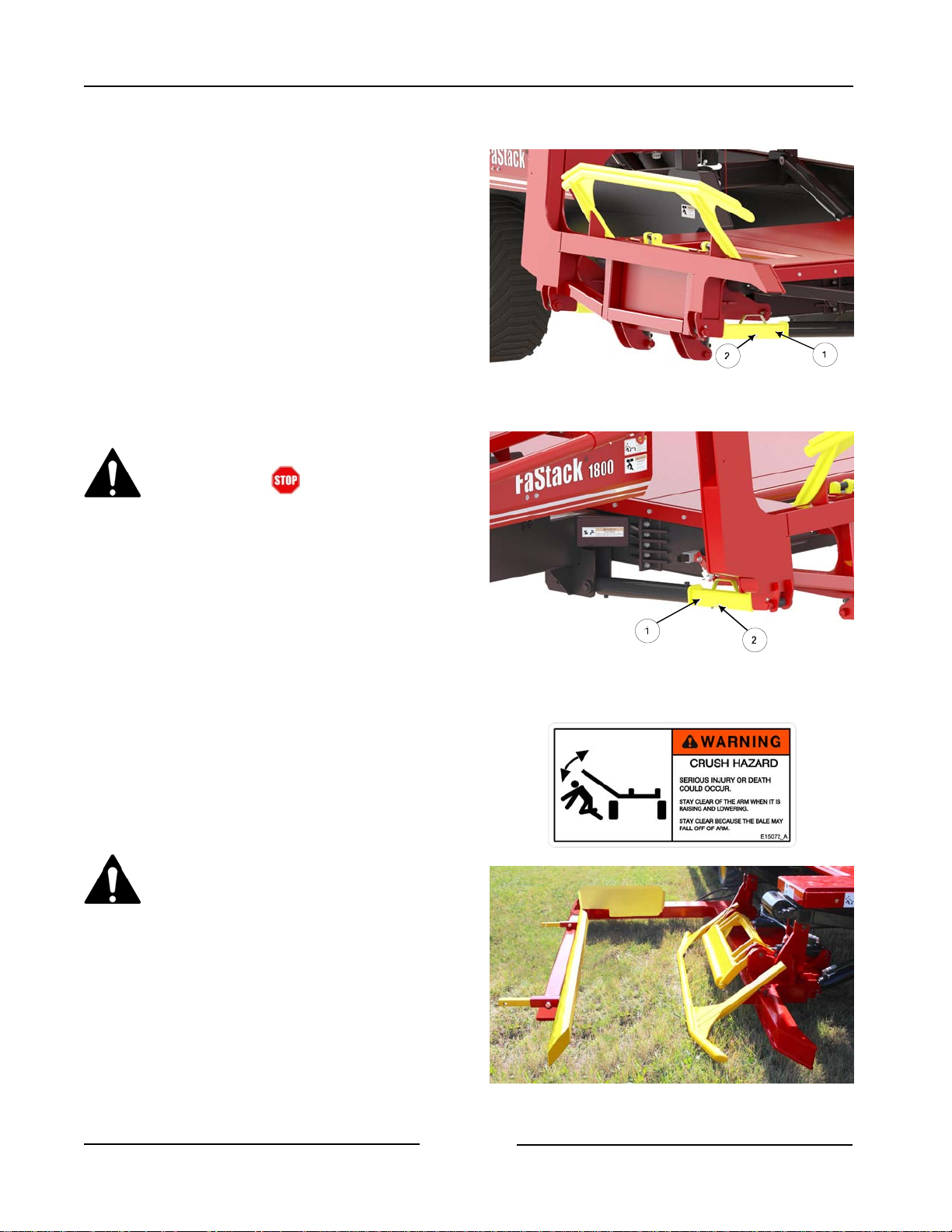
17. Activate the hydraulics and lock the
control valve to the open position.
- The hydraulic functions of the
stacker will be controlled with the
joystick and display.
18. If the lift arm cylinder locks are
installed:
- Raise the lift arm using the joystick
button to relieve any pressure on
the locks.
Before getting out of the tractor:
- Touch button on the
display.
- Shut off hydraulics.
- Shut down the tractor.
Remove the Front Lift Arm Transport Lock
218040C
- Remove the front and rear cylinder
locks and place in the storage
positions.
19. Lower the lift arm to allow the rear and
front tables to be lowered.
- Use the joystick button to lower the
lift arm.
Stand Clear of the Lift Arm.
A moving lift arm can cause
serious injury or death.
Never stand under the lift arm
when lowering or raising.
Do not allow people near the lift
arm when being moved.
Remove the Rear Lift Arm Transport Lock
218041C
Page 3-6
Lower the Lift Arm
219019
Page 42
Section 3 - Transporting the Bale Stacker
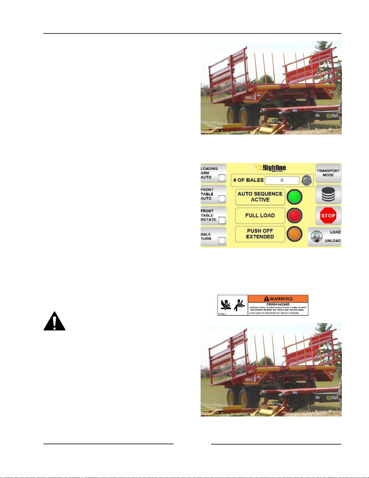
20. Lower the front table.
21. Touch the Unload button on the
display to turn on the unloading
functions of the machine and joystick
buttons.
- The toggle switch should be down
to indicate it is turned to unload
mode.
Note: Touching the button a second
time will toggle to the Load
mode.
22. Lower the rear table.
Lower the Front Table
Turn On the Unload Function
217146
219181
Stay clear when raising or
lowering the bale table.
Serious injury or death could occur
from crushing or pinching by the
table.
- Use the joystick to control the
cylinders for rear table movement.
Page 3-7
Lower the Rear Table
217146
Page 43
Section 3 - Transporting the Bale Stacker
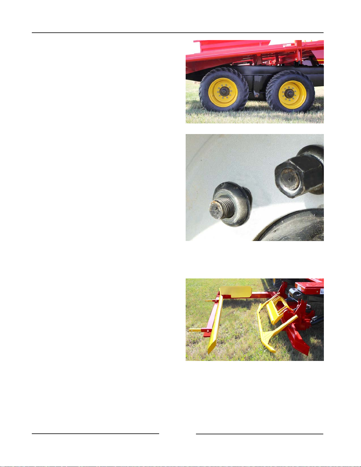
23. Check the condition of all the tires.
- Fill the tires to 40 psi (276 Kpa).
- Ensure that the flat portion of the
wheel stud washer is against the
wheel rim.
- Torque the lug nuts to 170 lb-ft
(230 Nm).
24. Touch the Load button on the display
to turn on the loading functions of the
machine and joystick buttons.
- The toggle switch should be up to
indicate it is turned to Load mode.
Check Condition of All the Tires
Flat of Washer Against Rim, Torque the Nuts
217147
217100
25. Close the clamp using the joystick
button.
Page 3-8
Close the Clamp
219019
Page 44
Section 3 - Transporting the Bale Stacker
26. Raise the lift arm using the joystick
button.
Stand Clear of the lift arm.
A moving lift arm can cause
serious injury or death.
Never stand under the lift arm
when lowering or raising.
Do not allow people near the lift
arm when being moved.
- Use the joystick to control the
cylinders to lift the lift arm.
27. Turn off the hydraulics.
- Turn off the tractor.
- Set the park brake on the tractor
before getting out of the tractor.
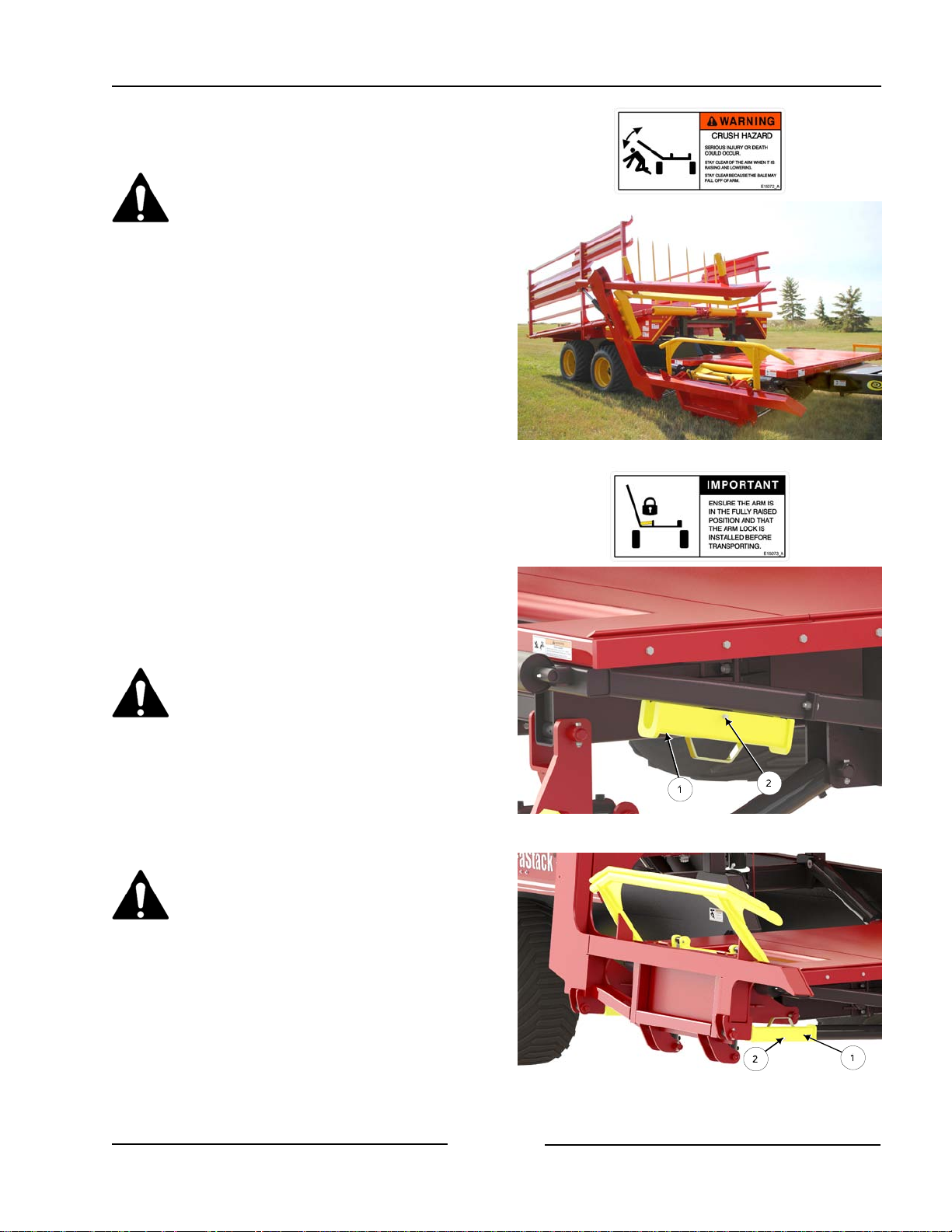
28. Remove the front lift arm transport
lock (1) from the storage position.
Always use the transport locks
when transporting the FaStack on
public roads. The lift arm may
descend rapidly if hydraulic
pressure is lost to the lift cylinders.
- Remove the clip pin (2) from the
storage tab.
Do not walk under the raised lift
arm until the front and rear locks
are secured in place.
Raise the Bale Lift Arm
Remove Front Lift Arm Lock from Storage
217148
218070C
29. Install the front lift arm transport lock
(1) onto the front cylinder.
- Fasten in place with the clip pin
(2).
Page 3-9
Install the Front Lift Arm Transport Lock
218040C
Page 45
Section 3 - Transporting the Bale Stacker
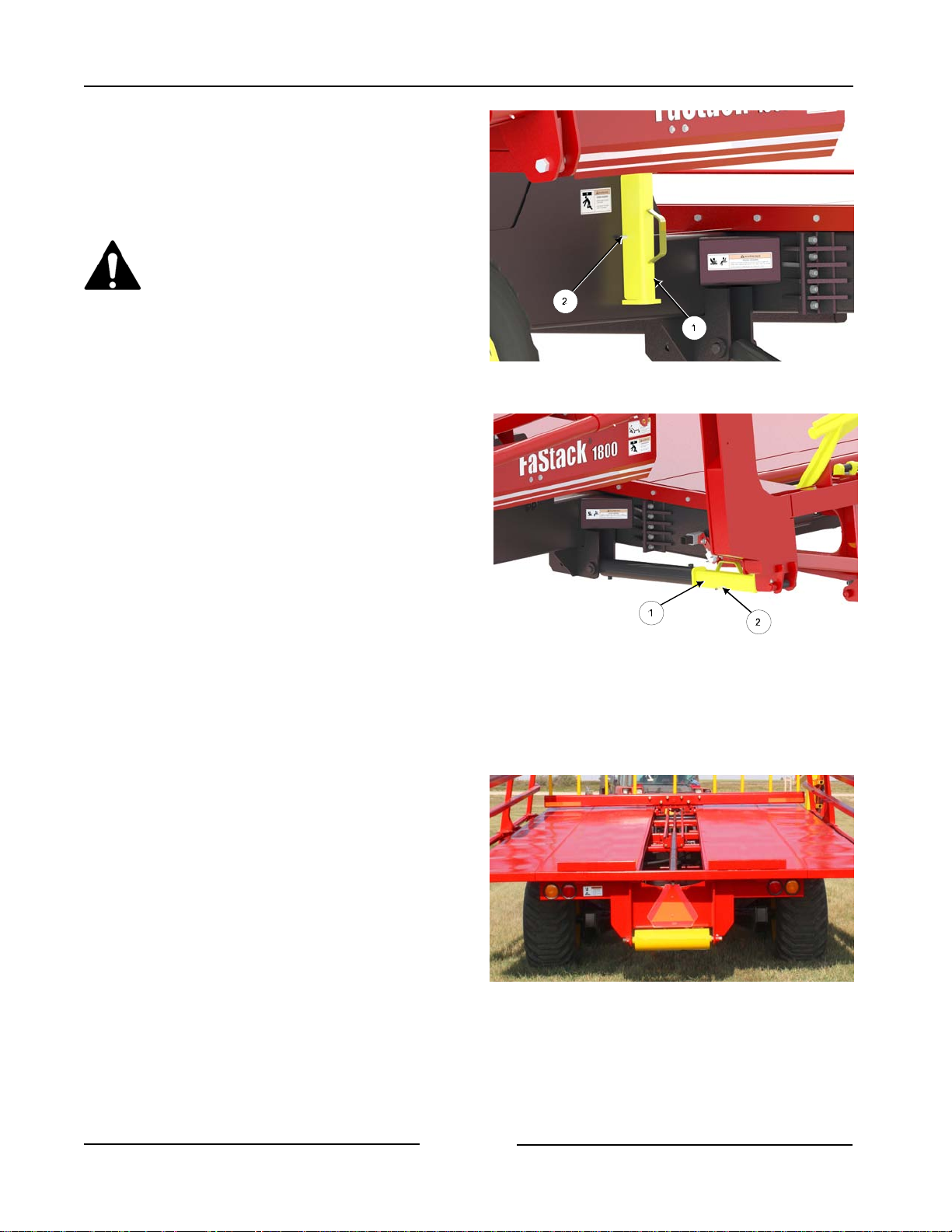
30. Remove the rear lift arm transport lock
(1) from the storage position.
- Remove the clip pin (2) from the
storage tab.
Do not walk under the raised lift
arm until the front and rear locks
are secured in place.
31. Install the rear lift arm transport lock
(1) onto the front cylinder.
- Fasten in place with the clip pin
(2).
32. Move the bale trolley to the front of
the table.
Remove Rear Lift Arm Lock from Storage
Install the Rear Lift Arm Transport Lock
218071C
218041C
- Touch the Unload button on the
display.
- Use the joystick button to move
the trolley forward.
Page 3-10
Move Trolley to the Front of the Rear Table.
217149
Page 46
Section 3 - Transporting the Bale Stacker
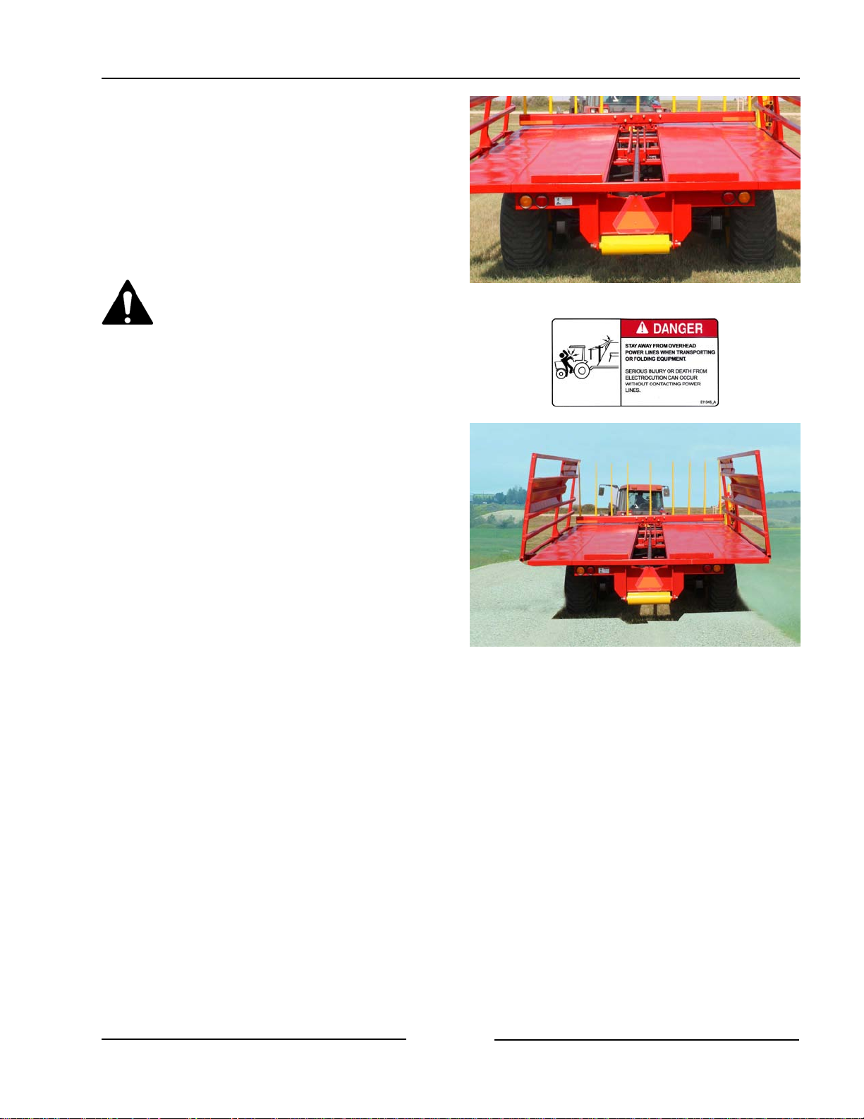
33. Ensure that the Slow Moving Vehicle
(SMV) sign and signal lights are clean
and visible.
34. Ensure the lights are working.
Stay away from overhead power
lines. Electrocution can occur
without contacting power lines
35. Transport Speed
- Do not exceed 20 mph (32 km/h)
when empty or 6 mph (10 km/h)
when fully loaded.
Note: Transport speed will need to be
lower when heavier bales are
loaded on the stacker.
36. If traveling on roadways:
- Disengage the hydraulic control
lever.
- Consult the local road regulations
regarding securing the load and
road travel. Follow all the
applicable regulations.
Ensure SMV is Visible and Lights Are Working
Travel On Roadways
217149
217150
Page 3-11
Page 47

Section 3 - Transporting the Bale Stacker
This Page Left Blank
Page 3-12
Page 48
Section 4 - Preparing the Bale Stacker
4.0 Preparing the Bale Stacker
1. Park the tractor and bale stacker on level
ground. Engage the tractor parking brake.
Shut down the tractor and remove
the key before repairing, servicing,
lubricating or cleaning the
machine.
Relieve all hydraulic pressure in
the hoses. Disconnect the
hydraulic hoses from the tractor
before going near the machine.
2. Ensure all decals are clean and in place.
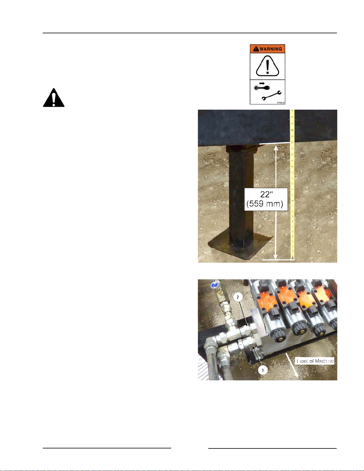
3. Check that the frame is 22" (559 mm) off
the ground.
Note: This frame height is important in
order for the bale clamp to operate
properly. If the frame is too low,
the bale clamp will come into
contact with the ground and
damage can occur.
- Adjust the hitch clevis for the frame to
be 22" (559 mm) off the ground when
connected to the tractor drawbar.
4. Attach the hydraulic hoses.
- The pressure hose from the tractor
must plug into the port of the hydraulic
block marked with "P" on the block
(2).
- The return hose from the tractor
must plug into the port of the
hydraulic block marked with "T" on
the block (3).
Frame Height at 22"
Pressure/Return Hoses on the Hydraulic Block
219031C
219056C
Page 4-1
Page 49
Section 4 - Preparing the Bale Stacker
- Clean the end of the hoses and the
connection.
- Firmly push the hoses into the tractor
receptacle.
- Route the hoses so they do not
interfere with moving parts.
5. Connect the lighting cable to the electrical
connection on the tractor.
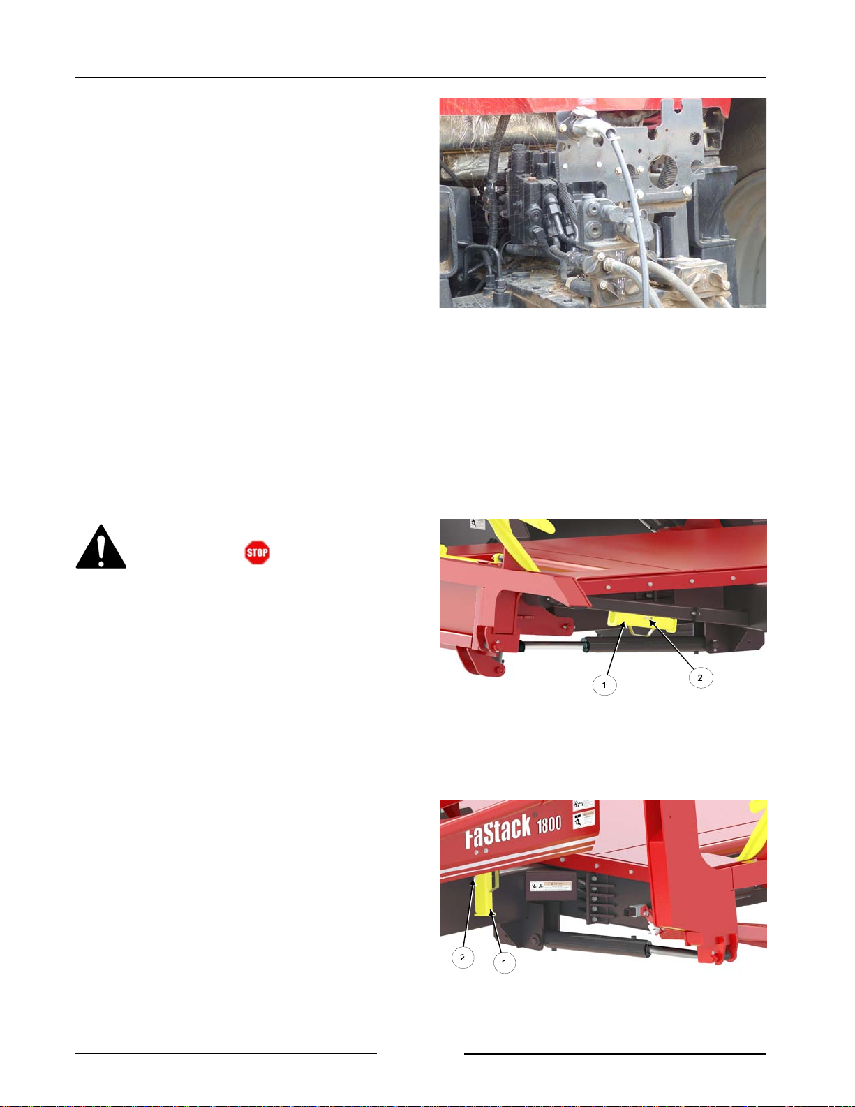
6. Remove the front transport lock (1) from
the bale lift arm cylinder.
- The lift arm may need to be raised
slightly to remove any pressure
that is on the transport lock.
- On the display touch the Load
button and use the joystick
button to raise the arm.
Attach Hydraulics and Lighting Cable
108008-1
Before getting out of the tractor:
- Touch button on the
display.
- Shut off hydraulics.
- Shut down the tractor.
Note: Do not lower the lift arm when the
transport locks are in position or
damage to the machine will occur.
- Place the lock in the storage position.
- Fasten with the clip pin (2).
7. Remove the rear transport lock (1) from
the bale lift arm cylinder.
- Place the lock in the storage position.
- Fasten with the clip pin (2).
Note: Do not lower the lift arm when the
transport lock is in position or damage
to the machine will occur.
Remove Front Lock, Place In Storage
218042-1C
Page 4-2
Remove Rear Lock, Place In Storage
218043C
Page 50
Section 4 - Preparing the Bale Stacker
8. Connect the tractor harness to the stacker
harness located on the hitch.
- See Section 3 for display and
joystick connections.
- Ensure the harness does not interfere
with or contact moving parts.
9. Connect the power cord into the keyed
and constant 12V DC power supply of the
tractor.
- Connect the round connector
power connector into the tractor
power receptacle.
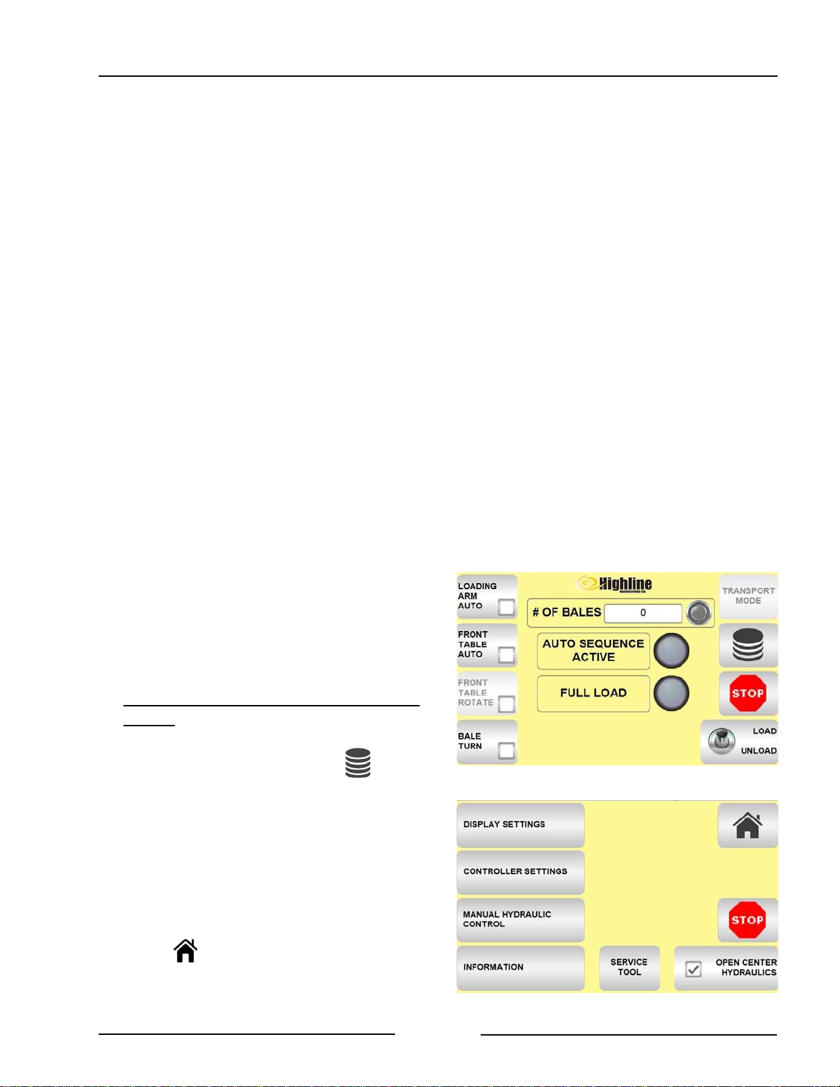
10. If needed, select for Open Center
Hydraulics.
• The Open Center Hydraulics
button will need to be selected on
the display.
• Two hydraulic valves will need to
be adjusted to compensate for
flow and pressure differences
between the two systems.
To select Open Center Hydraulics on the
display:
• Touch the Menu button on the
display home screen.
• Touch Open Center Hydraulics.
- There should be a check mark
in the small box to indicate it is
turned on.
Display Home Screen
219164
• Touch the Home Screen button
to return to the Home Screen.
Page 4-3
Select Open Center Hydraulics - Menu Screen
219170-1
Page 51
Section 4 - Preparing the Bale Stacker
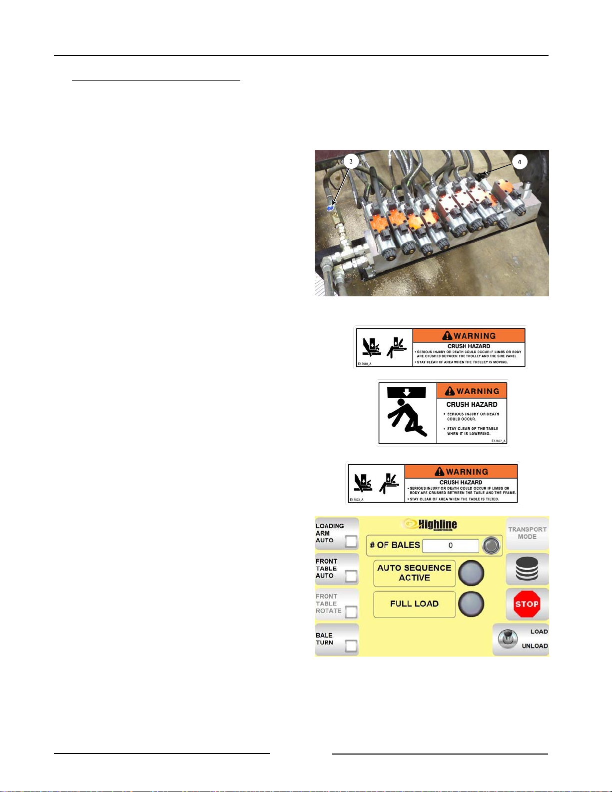
To adjust the 2 hydraulic valves:
• At the Home Screen touch the Unload
button.
• Set the tractor engine to the speed for
operating the hydraulics.
• Adjust boost cylinder bleed valve (3).
- Close the valve completely.
- Engage the tractor hydraulics.
- Open the valve just enough so the
boost cylinder does not raise the
rear table.
• Adjust the trolley pressure valve (4).
- Move the trolley to the front of the
rear table.
- Close the trolley valve adjustment
knob.
- Completely raise the rear table.
- Open the trolley adjustment knob
just enough so the trolley begins to
creep down the table. (This is an
initial setting and may need to be
adjusted depending on how well
the bales are loading onto the rear
table.)
- Secure the valve adjustment knob
in place.
13. Touch the Load button on the Home
Screen to turn on the loading
functions of the machine and joystick
buttons.
- The toggle switch should be up to
indicate it is turned to Load mode.
Adjust Boost Bleed Valve and Trolley Valve
219034C
Note: Touching the button a second
time will toggle to the Unload
mode.
Page 4-4
Turn on the Load Function
2191641
Page 52
Section 4 - Preparing the Bale Stacker
14. Use the joystick button to lower the lift
arm.
Stand Clear of the lift arm.
A moving lift arm can cause
serious injury or death.
Never stand under the lift arm
when lowering or raising.
Do not allow people near the lift
arm when being moved.
Note: Do not lower the lift arm when the
transport locks are in position or
damage to the machine will occur.
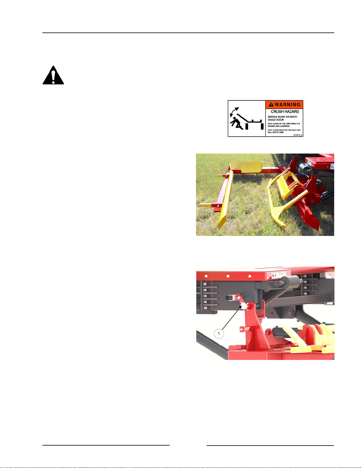
15. Check the condition of the rotation
sensor (1) mounted on the rear of the
lift arm.
- Check that the sensor (1) is in
good condition.
- Check that the area around the
sensor is free from debris.
- Check that the electrical connector
is tight.
- See Section 6 for more information
on rotation sensor adjustment.
Lower the Lift Arm
Check the Condition of the Rotation Sensor
219019
218045C
Page 4-5
Page 53
Section 4 - Preparing the Bale Stacker
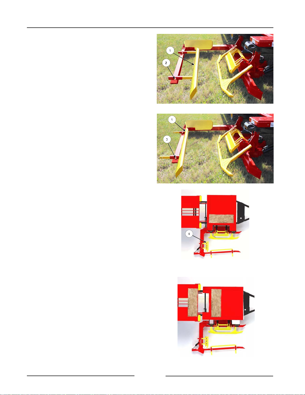
16. Adjust the lift arm for the size of the
bales.
- Remove the bolts from the adjustable
holder (1) on the clamp.
- For 3' x 3' (0.9 m) bales, move the
adjustable holder (1) towards the
front table. Place the bolts in the
tube holes (2).
- For:
- 3' x 4' (0.9 m x 1.2m) bales
with 4' [1.2m] side on the
ground
- 4' x 4' (1.2 m x 1.2 m) bales
- Move the adjustable holder (1)
away from the front table.
Place the bolts in the tube
holes (3).
- Fasten in place with the bolts.
Adjust Arm for 3 Foot (0.9 m) Bales
Adjust Arm for 4 Foot (1.2 m) Bales
219035C
219019C
17. On the FaStack 1200 Flex adjust the
spring loaded bar (4) on the lift arm for
the length of the bales.
- It is important to adjust this bar so
the bale will be centered on the
front table in the front to back
position.
- After the front table is rotated the
bale will be centered on the rear
table.
Adjust the Spring Bar to Center
Bale on the Front Table
Bale Centered on Rear Table
217180-1C
217180-2
Page 4-6
Page 54
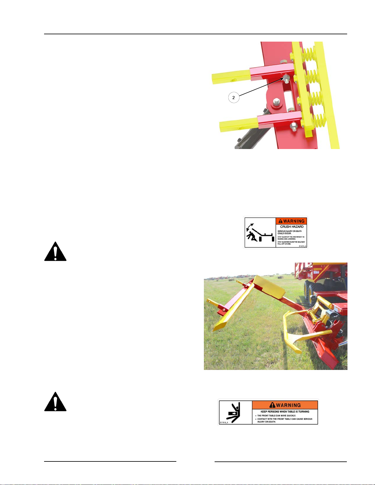
Section 4 - Preparing the Bale Stacker
- To adjust the spring loaded bar:
- Remove the bolts in the
adjustment tubes (2).
- Slide the bar to the desired
location for the size of bale being
loaded.
- Fasten in place with the bolts (2).
18. Use the joystick buttons to check that
the lift arm operates freely.
- It is normal operation if the lift
arm quickly moves downward
during its cycle.
Stand Clear of the Bale Lift Arm
- A moving lift arm can cause
serious injury or death.
- Never stand under the lift arm
when lowering or raising.
- Do not allow people near the lift
arm when the being moved.
Adjust Spring Loaded Bar
218044-1C
19. On the FaStack 1200 Flex check that
the front table rotates freely.
Stay clear of the table when
turning. The front table can move
quickly. Contact with the front table
can cause serious injury or death.
Page 4-7
Check that Lift Arm Operates Freely
219036
Page 55
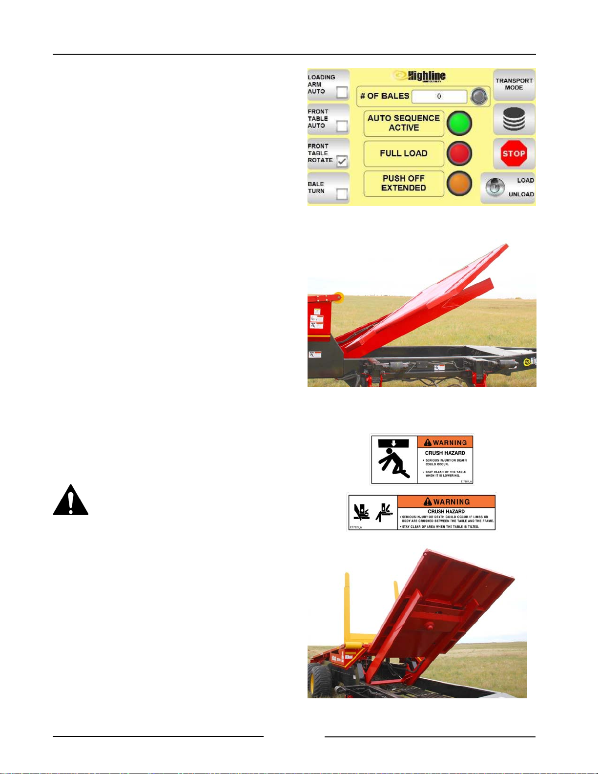
Section 4 - Preparing the Bale Stacker
- Lower the lift arm.
- On the display touch FRONT
TABLE ROTATE.
- Use the joystick buttons to raise
the front table.
- As it is rising the table should
rotate.
20. Check that the front table raises and
lowers freely.
Stay clear when raising or lowering
the tables. Serious injury or death
could occur from contact with the
moving table.
Push Front Table Rotate Button
Check the Front Table Rotates (1200 Flex)
219182
218074
- Lower the lift arm.
- Press the Load button on the
display.
- Use the joystick buttons to raise
and lower the front table.
Page 4-8
Check The Front Table Raises and Lowers
(1200 Flex Shown)
217202
Page 56
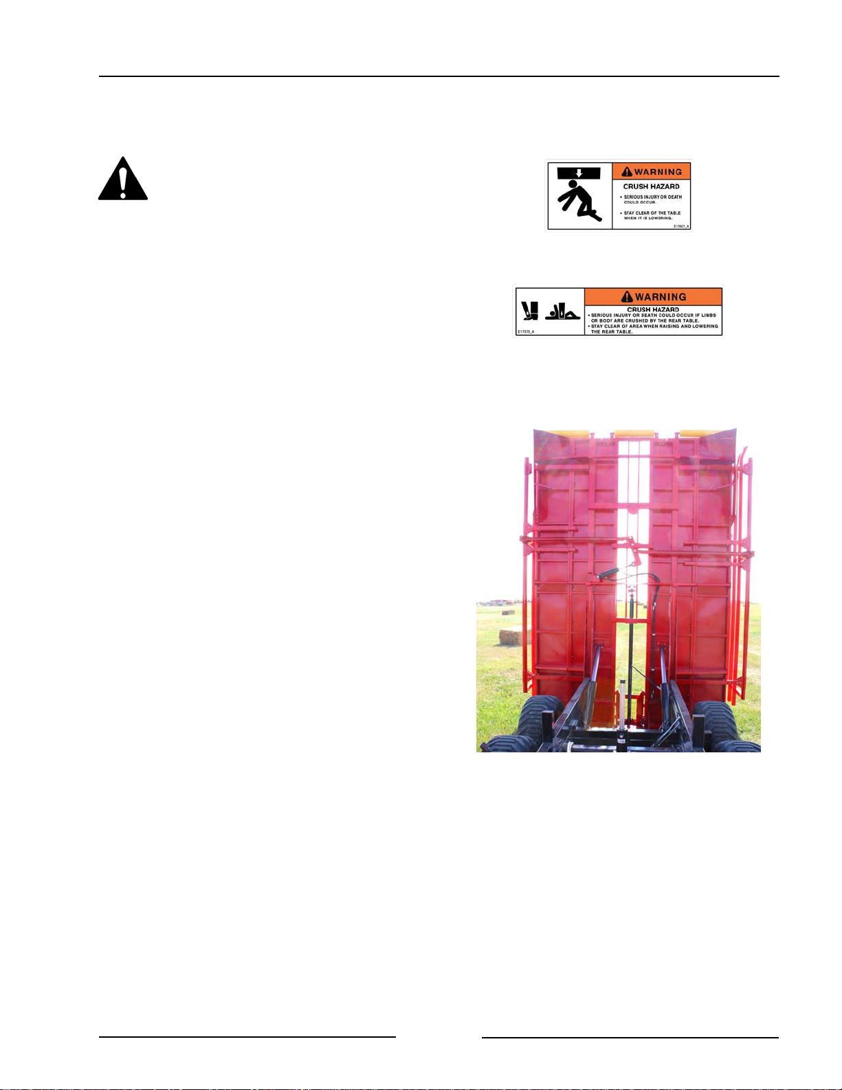
Section 4 - Preparing the Bale Stacker
21. Check that the rear table raises and
lowers freely.
Stay clear when raising or lowering
the table. Serious injury or death
could occur from contact with the
moving table.
- Lower the lift arm.
- Lower the front table.
- Press the Unload button on the
display.
- Use the joystick buttons to raise
and lower the rear table.
Page 4-9
Check The Rear Table Raises and Lowers
217155
Page 57
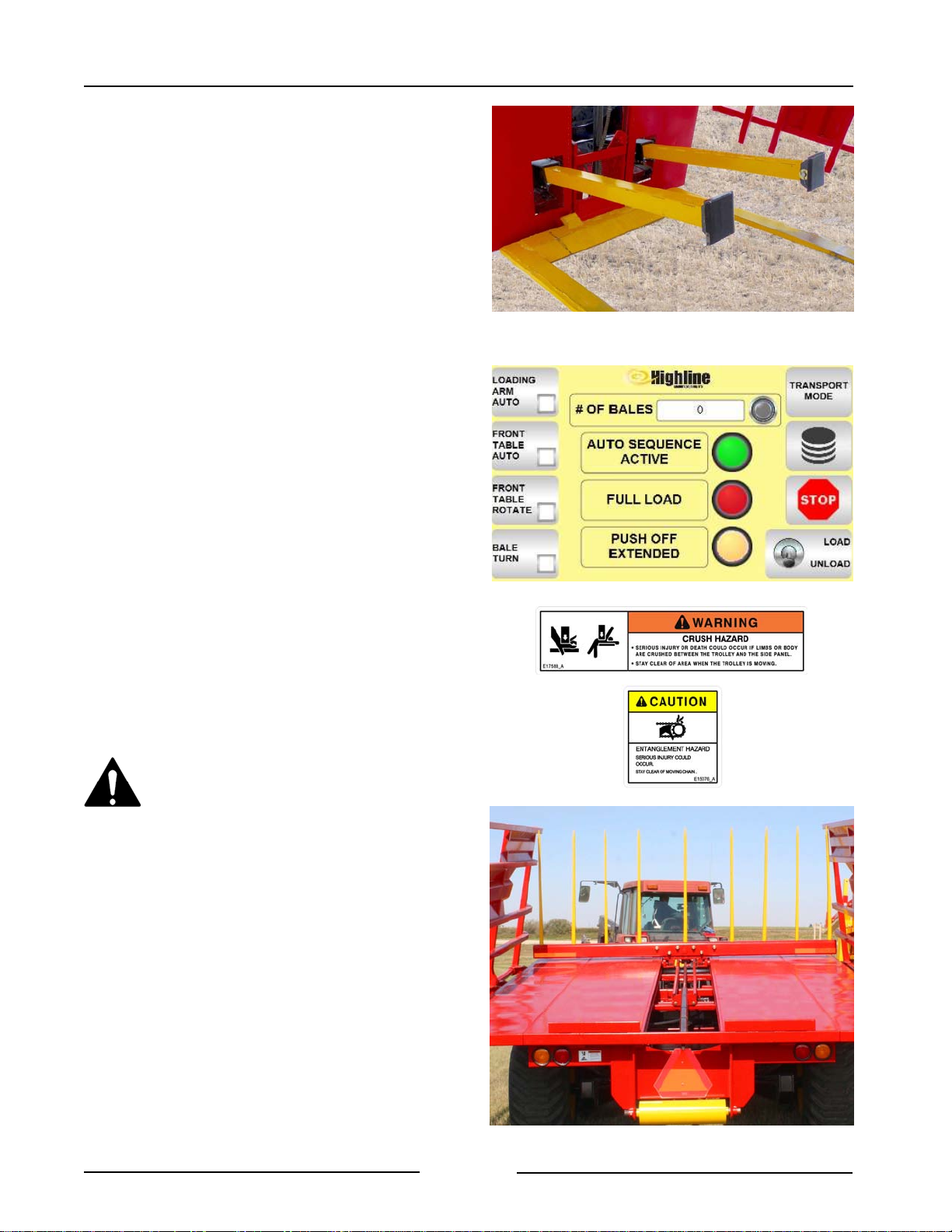
Section 4 - Preparing the Bale Stacker
22. FaStack 1200 Flex - Check that the
pushoffs fully extend and retract.
- Push the Unload button on the
display.
- Raise the rear table to 90 degrees.
- Push the joystick buttons to extend
and retract the pushoff cylinders.
- When the cylinders are extended
the light on the display beside
PUSH OFF EXTENDED should
come on.
- When the cylinders are fully
retracted the light will go off.
Check the Pushoffs Extend/Retract
(1200 Flex)
216057
- Lower the rear table.
Note: If the joystick button to
lower the rear table is
pushed while the pushoffs
are extended, the pushoffs
will retract before the table
is able to lower.
23. Check that the bale trolley on the rear
table operates freely.
Keep clear of machine when
moving the trolley.
Contact with the moving trolley or
the moving chain could cause
serious injury or death.
- Push the Unload button on the
display.
- Push the joystick button to move
the trolley towards the front of the
table.
Push Off Extended Warning Light
219181-1
- To move the trolley to end of
the rear table, raise the rear
table. The trolley will move
down under it's own weight.
Page 4-10
Check The Trolley on Rear Table
217160
Page 58
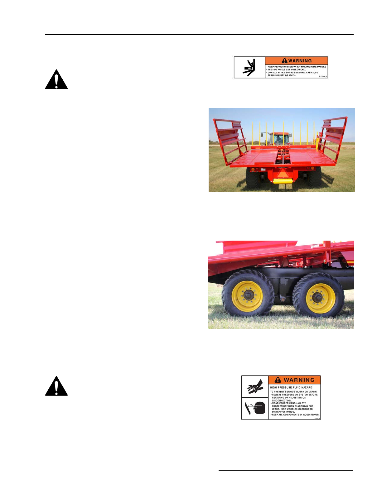
Section 4 - Preparing the Bale Stacker
24. Check that the side racks open and
close.
Keep persons back when moving
the side panels. The side racks
can move quickly. Contact with a
moving side rack can cause
serious injury or death.
- Push the Unload button on the
display.
- Use the joystick buttons to open
and close the side rack.
- On the FaStack 1200 Flex the
side racks are an option. They
may be not be present.
25. Check the condition of the tires.
- Fill to an air pressure of 40 psi
(276 kPa).
- Torque the lug nuts to 170 lb-ft
(230 Nm).
- Inspect the wheels and tires for
damage or foreign objects. Repair
or replace as necessary.
26. Inspect all the hydraulic cylinders and
hoses.
Check that the Side Racks Open and Close
Check the Condition of the Tires
217161
217147
Use a piece of cardboard or heavy
paper to check for leaks. Do not
use your hand. Wear proper hand
and eye protection when searching
for leaks.
Relieve pressure on hydraulic
system before repairing, adjusting
or disconnecting.
Page 4-11
Page 59
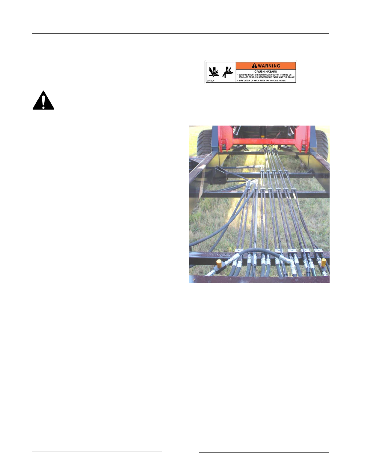
Section 4 - Preparing the Bale Stacker
Note: If fluid is injected under the skin, it
must be removed immediately by a
surgeon familiar with this type of
injury.
Do not go under a raised table.
Serious injury or death could
occur from the table lowering.
- Visually inspect all the hydraulic hoses
and fittings.
- See Section 6 for conditions
indicating that hose replacement is
needed.
- Ensure the proper size cylinder pins
are in place and secured.
27. Lubricate all grease fittings. (See
Section 6).
Check All Hydraulic Connections
217073
Page 4-12
Page 60
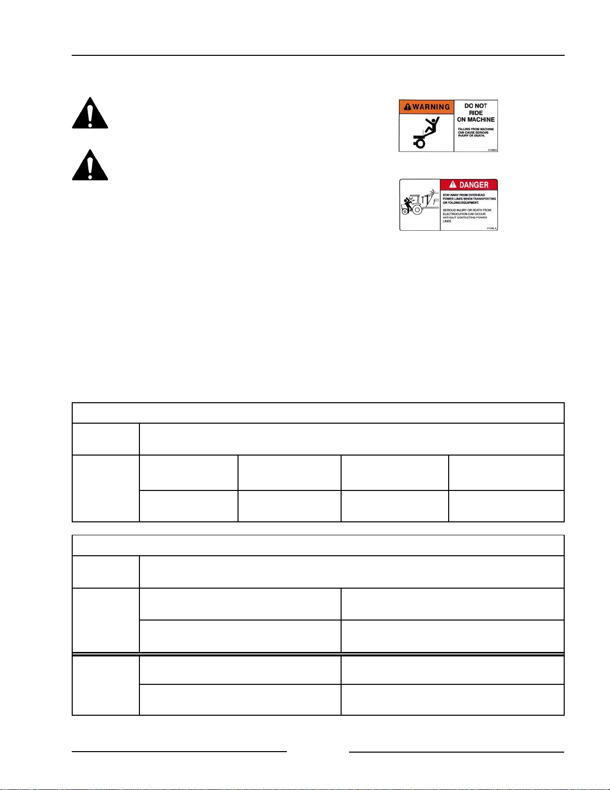
Section 5 - Operating the Bale Stacker
5.0 Operating the Bale Stacker
Do not allow anyone to ride on
the bale stacker. Falling from the
machine can cause injury.
Stay clear of overhead power
lines. Electrocution can occur
without contacting the power
lines.
Tractor Hitch Category Requirement
The category of tractor hitch that is required
will be determined by the weight of the bales
being loaded. The weight of the bales
influence the vertical hitch load.
Note: It is the operator's responsibility to
ensure the appropriate tractor is used that
can handle the vertical hitch loads as
listed.
See the chart for the category of tractor hitch
required for the listed bale sizes and weights.
FaStack 1800
Hitch
Category
4x4:
1400 lbs (635 kg)
4
Vertical Hitch Load:
7150 lbs (3243 kg)
Hitch
Category
4x4 or 3x4 Off String:
1200 lbs (544 kg)
3
Vertical Hitch Load:
5940 lbs (2694 kg)
Maximum Bale Weight
3x4 Off String:
1100 lbs (499 kg)
Vertical Hitch Load:
7340 lbs (3329 kg)
FaStack 1200
Maximum Bale Weight
3x4 On String:
1400 lbs (635 kg)
Vertical Hitch Load:
7300 lbs (3311 kg)
3x4 On String or 3x3:
1000 lbs (454 kg)
Vertical Hitch Load:
5840 lbs (2649 kg)
3x3:
1000 lbs (454 kg)
Vertical Hitch Load:
7410 lbs (3361 kg)
4x4 or 3x4 Off Strings:
1800 lbs (816 kg)
4
Vertical Hitch Load:
7250 lbs (3289 kg)
Page 5-1
3x4 On String or 3x3:
1600 lbs (726 kg)
Vertical Hitch Load:
7360 lbs (3338 kg)
Page 61
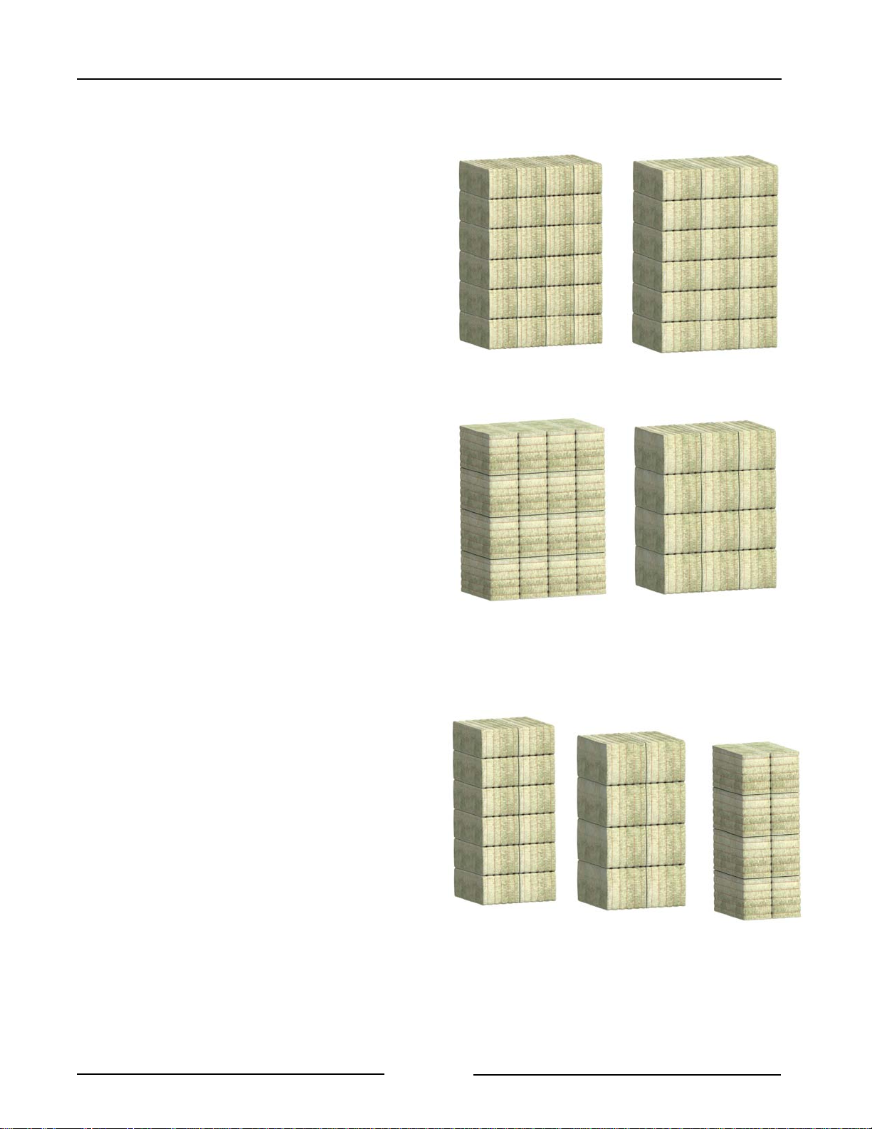
Section 5 - Operating the Bale Stacker
Number Of Bales Capacity
The number of bales that can be stacked is
determined by the size of bale and the
orientation of the bale.
The FaStack can stack the bales "On
Strings" (strings down) or "Off Strings"
(strings on the side).
FaStack 1800
- 24 bales of 3' x 3' bales
- 18 bales of 3' x 4' bales on strings
- 16 bales of 3' x 4' bales off stings
- 12 bales on 4' x 4' bale on or off
strings
FaStack 1800 Bale Capacity
24 Bales of 3'x3'
On of Off Strings
217163
18 Bales of 4'x3'
On Strings
217164
FaStack 1200 Flex
Fastack Flex indicates the ability to stack
bales from the end of the stack giving
the user more flexibility as to where the
bales can be stacked whether it be in the
field or in a shed. The rotating front table
allows stacking along the long side of the
bale.
- 12 bales of 3' x 4' on strings
- 8 bales of 4' x 4' on or off strings
- 8 bales of 3' x 4' off stings
16 Bales 4'x3'
Off Strings
217165
12 Bales of 4'x4'
On or Off Strings
FaStack 1200 Flex Bale Capacity
12 Bales 3'x4'
On Strings
217167
8 Bales 4'x4'
On or Off Strings
217168
217166
8 Bales 3'x4'
Off Strings
217169
Page 5-2
Page 62
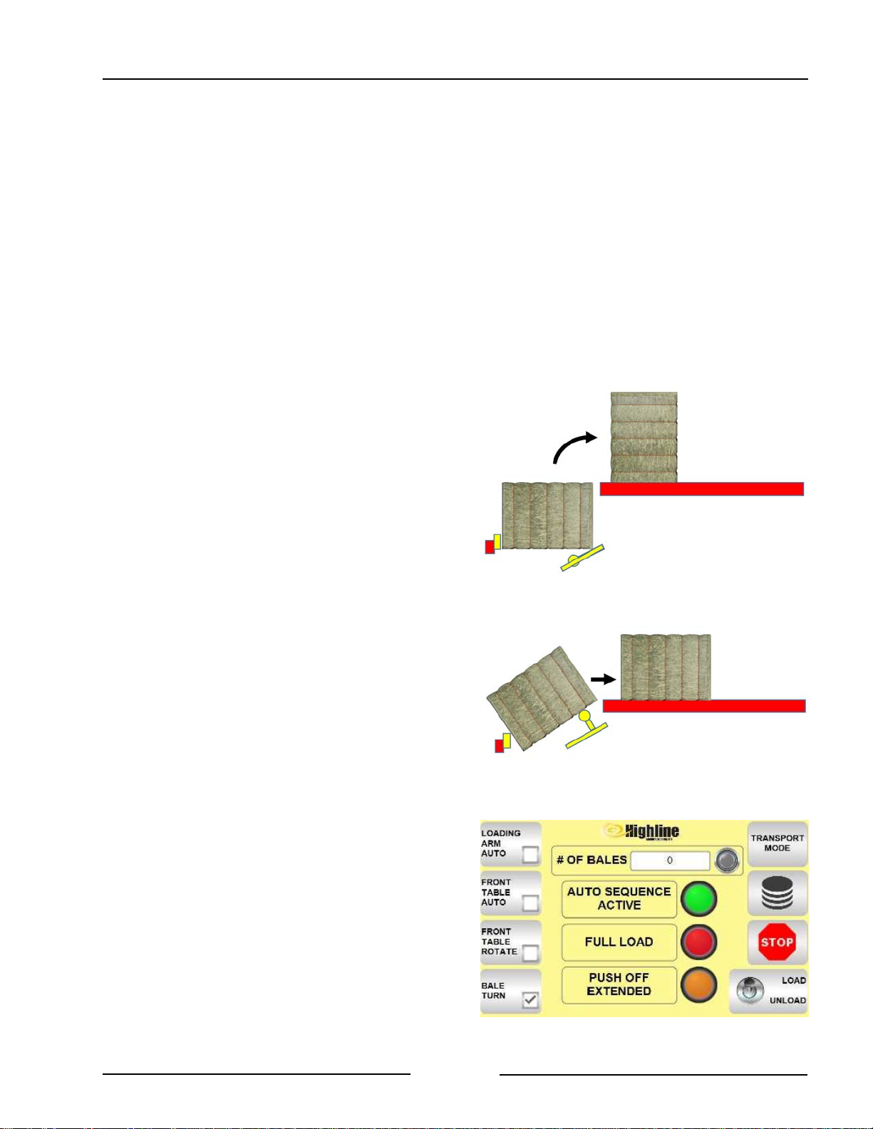
Section 5 - Operating the Bale Stacker
"On Strings" or "Off Strings" Stacking
The position of the bale strings when loaded
on the front table will be the same position
of the strings in the unloaded stack.
The unloaded stacking of "On Strings"
(strings down) or "Off Strings" (strings on
the side) is determined by 2 factors while
loading:
1. The position of the bale strings when
the bale is on the ground.
2. Whether or not the bale is turned
when loading onto the front table.
The bale is handled in the following way
depending on the display choice:
- Bale Turn On = Bale is rotated
(turned) 90° from
field position when
loading.
- Bale Turn Off = Bale is loaded in
the same
orientation as field
position.
Before picking up bales determine the
position of the bale strings in the field and
the desired way of stacking.
- If Bale Turn is desired touch the
BALE TURN button on the display.
- There should be a check mark
in the small box to indicate it is
turned on.
Bale Turn On
Bale Turn Off
217172-2
217172-1
Page 5-3
Bale Turn Button On
219182-1
Page 63
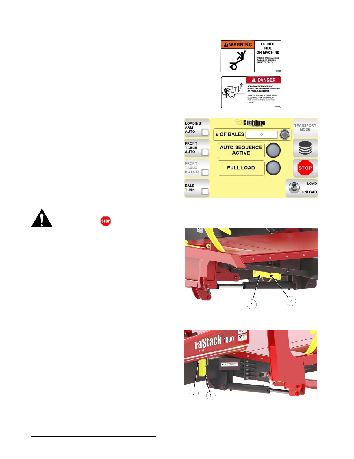
Section 5 - Operating the Bale Stacker
LOADING BALES IN THE FIELD
1. Drive the bale stacker into the field area.
2. Park on level ground.
3. Engage the hydraulic lever and lock it in
the open position.
4. On the display touch the Load Button so
the joystick buttons operate the functions
required to pick up the bales.
- The toggle switch should be up to
indicate it is turned to load mode
5. Raise the lift arm to remove any
pressure that may be on the transport
locks.
Touch Load Button
219164
Before getting out of the tractor:
- Touch button on the
display.
- Shut off hydraulics.
- Shut down the tractor.
6. Remove the front transport lock (1) from
the bale lift arm cylinder.
Note: Do not lower the lift arm when the
transport lock is in position or
damage to the machine will occur.
- Place the lock in the storage position.
- Fasten with the clip pin (2).
7. Remove the rear transport lock (1) from
the bale lift arm cylinder.
- Place the lock in the storage position.
- Fasten with the clip pin (2).
Remove Front Lock, Place In Storage
218042-1C
Note: Do not lower the lift arm when the
transport lock is in position or
damage to the machine will occur.
Page 5-4
Remove Rear Lock, Place In Storage
218043C
Page 64
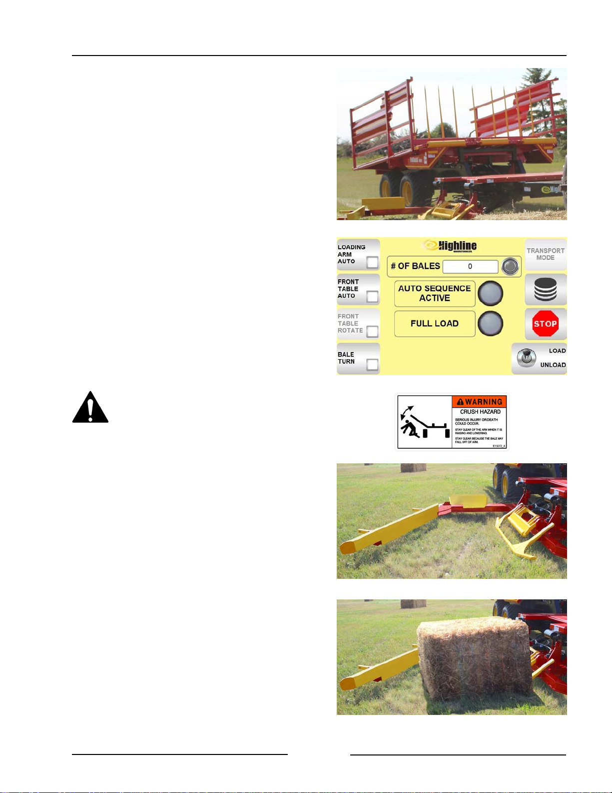
Section 5 - Operating the Bale Stacker
Loading the Front Table
There are 2 options for loading the Front
table:
! Loading Arm Manual Control
- See page 5-5
! Loading Arm Auto Control
- See page 5-7
Loading the Front Table
Loading Arm Manual Control
- Ensure the Loading Arm Auto of the
display is off.
- Push the joystick button to ensure the
front the table is completely down.
- This will allow the lift arm to raise.
Lower Front Table ,Lower Lift Arm
219037
- Push the joystick button to lower the
lift arm.
Stay clear when lowering the lift
arm to avoid serious injury or
death.
- The lift arm should be a few inches
above the ground to avoid contacting
the ground.
Note: If the arm is contacting the
ground, adjust the frame
height and hitch clevis. See
Section 4 for information.
- Push the joystick button to open the
clamp arm.
- Drive up to the bale and position the
lift arm until it is around the bale.
Loading Arm Auto Off
Open Clamp Arm
219164
219038
Note: Avoid putting loose bales into
the first couple of rows. Loose
bales on the bottom or middle
of the stack could make the
stack less stable.
Page 5-5
Drive Up to the Bale Until Arm is Around Bale
219039
Page 65
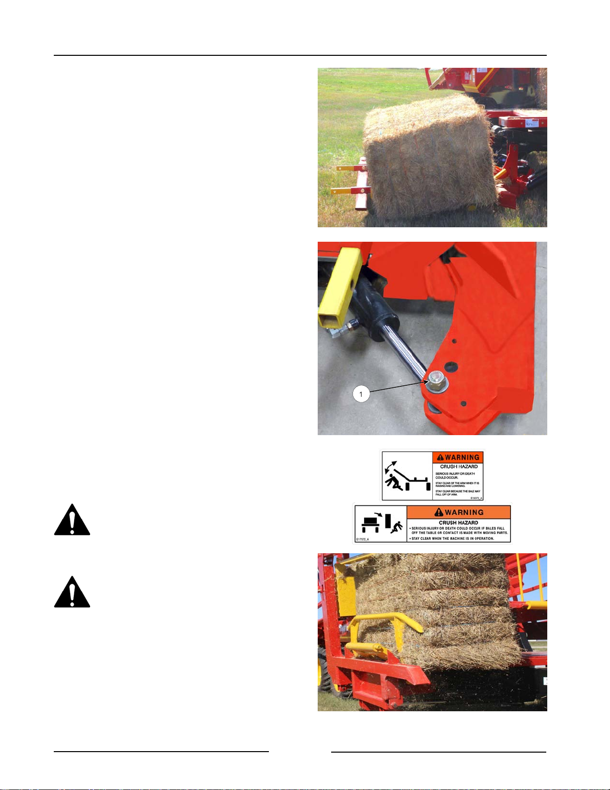
Section 5 - Operating the Bale Stacker
- Drive forward until the bale is fully
against the spring bar at the back of
the lift arm.
- The bale stacker may be operated at
field speeds of 3 - 4 mph (4 - 6 km/h).
- It is not required to stop to pick up
a bale.
- Push the joystick button to close the
clamp arm.
Note: If the clamp arm pushes the bales
to far up onto the arm causing the
bale to wedge against the front
table, adjust the clamp arm
cylinder position.
- Move the cylinder bolt (1) to
the next hole on the clamp
arm.
- Push the joystick button to raise the
lift arm and place the bale on the
front table.
Stay clear when lowering the lift
arm to avoid serious injury or
death.
Close the Lift Clamp
Move Cylinder to Reduce Bale Wedging
219040
219041C
Stay clear when lifting bales. If a
bale falls off it can cause serious
injury or death.
Page 5-6
Raise the Lift Arm to Place Bale on the Table
219042
Page 66
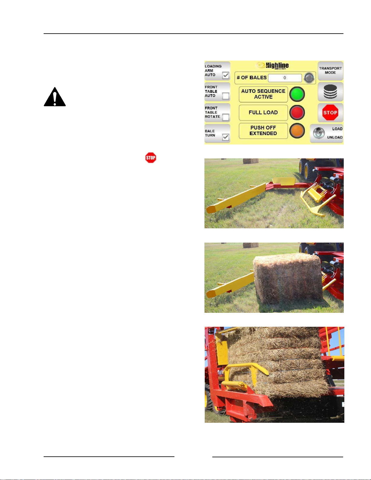
Section 5 - Operating the Bale Stacker
Loading the Front Table
Loading Arm Auto Control
The Loading Arm Auto feature enables
using 2 single button presses to pick a bale.
Keep people clear of the
machine when in Auto mode.
Parts of the machine will move
without operator control and
move unexpectedly.
Note: The Auto function can be stopped
at anytime by pressing the
joystick button or the button.
- Press the LOADING ARM AUTO on
the display.
- There should be a check mark in
the small box to indicate it is
turned on.
- On the joystick press the Arm Down
button.
- This moves the loading arm down
from the ready position to the
loading position. The clamp will
also open.
Note: The "Ready" position is the
arm raised about 30
degrees from the ground
with the clamp open.
- Drive so the bale is inside the arm.
Enable Loading Arm Auto
Press Arm Down - Arm Lowered & Clamp Open
Drive Up to the Bale Until Arm is Around Bale
219182-2
219038
219039
- On the joystick press the Arm Up
button.
- The Auto Sequence Active light
will come on to show that the
Loading Arm Auto is in process.
- The clamp will close and lift the
bale onto the table.
- If the Bale Turn has been
turned on at the display the
bale will be turned in the
sequence.
- The loading arm will then move
back to the Ready position.
Page 5-7
Press Arm Up- Bale Placed on the Table
219042
Page 67
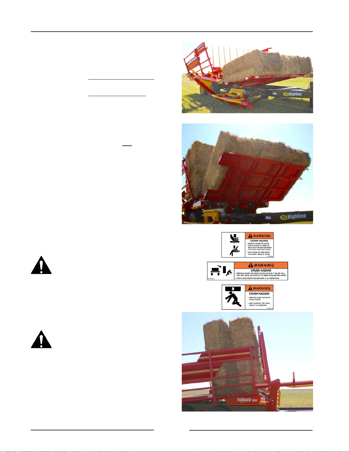
Section 5 - Operating the Bale Stacker
FaStack 1800 Front Table Raise
There are 2 options for the FaStack 1800
Front table raise:
! Front Table Manual Raise Control
- See page 5-8
! Front Table Auto Raise Control
- See page 5-9
FaStack 1800 Front Table Raise
Manual Control
Note: The display should not have the
Front Table Auto checked.
- Lower the arm before lifting the front
table.
- Use the joystick button to raise the
front table up to move the bales onto
the rear table.
- As the front table is being raised,
the side racks will open to allow
the bales to move onto the rear
table.
Stay clear when raising or
lowering the tables. Serious injury
or death could occur from contact
with the moving table. There is a
crushing hazard if limbs or body is
placed between the hitch and
table when the table deck is
lowered.
Lower Arm Before Lifting Front Table
Lift Front Table
219043
217177
Stay clear when front table is
lifted because bales could fall.
- As the bales are pushed onto the
rear table the bales already on the
table are pushed back and the trolley
will also be pushed back.
- The side racks will close.
- Lower the front table.
Page 5-8
Fully Raise the Front Table, Close Side Racks
217178
Page 68
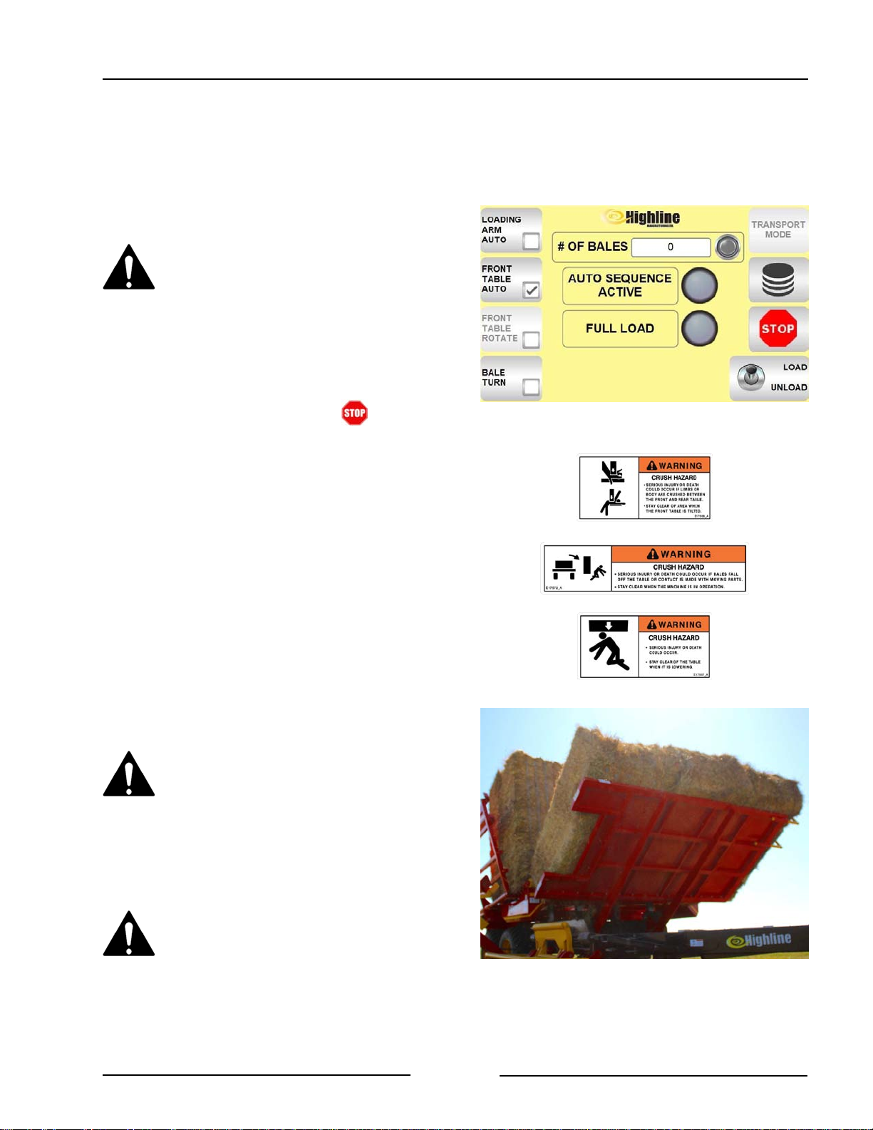
Section 5 - Operating the Bale Stacker
FaStack 1800 Front Table
Auto Raise
The Front Table Auto feature enables using
a single button press to load the bales from
the front table onto the rear table and then
lower the front table.
Keep people clear of the
machine when in Auto mode.
Parts of the machine will move
without operator control and
move unexpectedly.
Note: The Auto function can be stopped
at anytime by pressing the
joystick button or the button.
- Select Front Table Auto on the
display.
- There should be a check mark in
the box to indicate it is turned on.
Press Front Table Auto
219164-1
- Lower the lift arm.
- On the joystick press the Front Table
Up button.
- The Auto Sequence Active light
will come on to show that the
Front Table Auto is in process.
- The front table will rise and the
side racks will open.
Stay clear when raising or
lowering the tables. Serious injury
or death could occur from contact
with the moving table. There is a
crushing hazard if limbs or body is
placed between the hitch and
table when the table deck is
lowered.
Stay clear when front table is
lifted because bales could fall.
- The bales will be moved onto the
rear table.
- The side racks will close.
- The front table will lower.
Press Front Table Up - Raise Front Table
217177
Page 5-9
Page 69
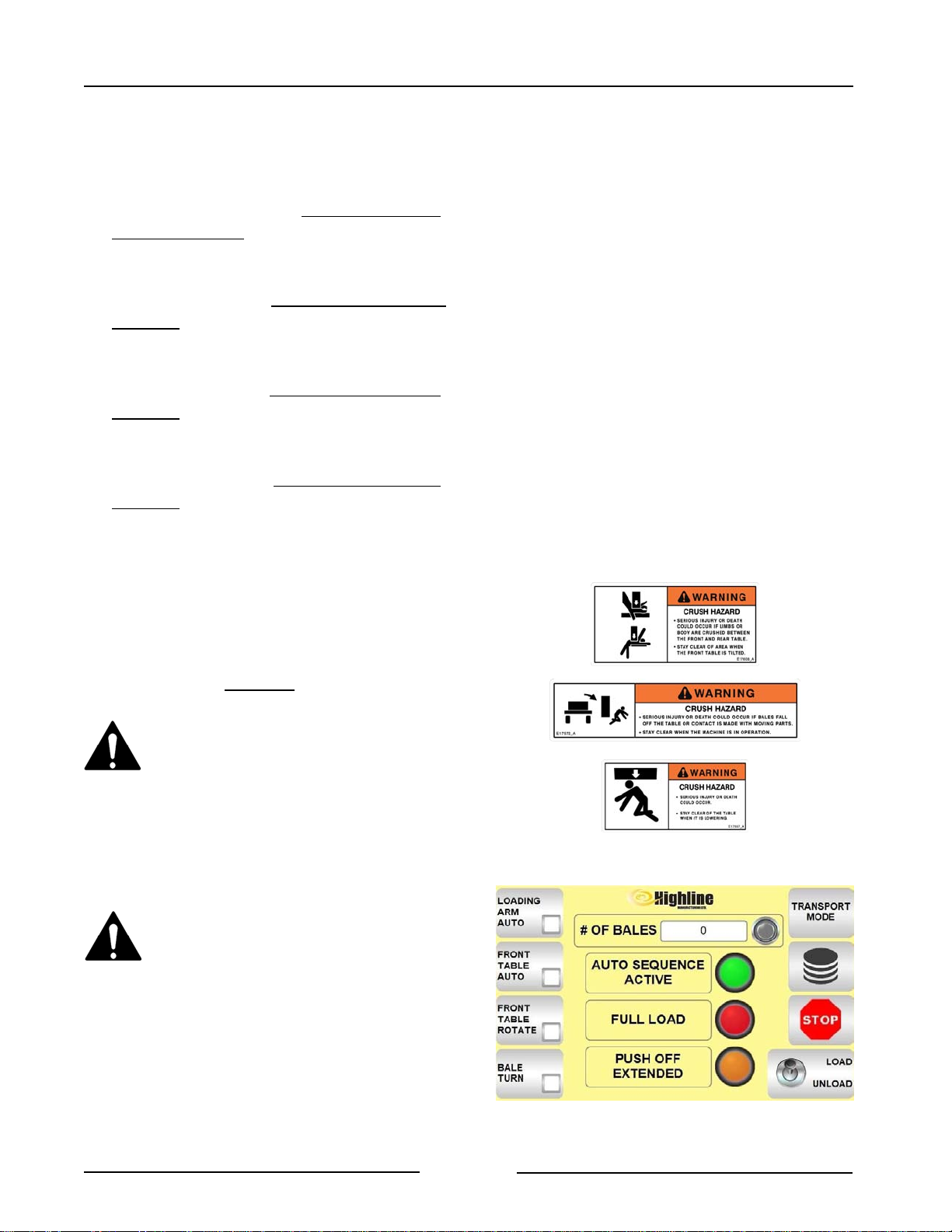
Section 5 - Operating the Bale Stacker
FaStack 1200 Front Table Raise
There are 4 options for the FaStack 1200
Front table raise:
! Front Table Raise Manual Control
without rotating the bales.
- See page 5-10.
! Front Table Raise Manual Control with
rotating the bales.
- See page 5-11
! Front Table Raise Auto Control without
rotating the bales.
- See page 5-13
! Front Table Raise Auto Control with
rotating the bales.
- See page 5-14
The factors for choosing to rotate bales
depends on stacking location and the choice
of "On Strings" or "Off Strings" stacking.
FaStack 1200 Front Table Raise
Manual Control Without Rotating Bales
Stay clear when raising or
lowering the tables. Serious injury
or death could occur from contact
with the moving table. There is a
crushing hazard if limbs or body is
placed between the hitch and
table when the table deck is
lowered.
Stay clear when front table is
lifted because bales could fall.
- Ensure the Front Table Rotate on the
display is off.
- Lower the lift arm before raising the
front table.
Page 5-10
Front Table Rotate Turned Off
219163-3
Page 70
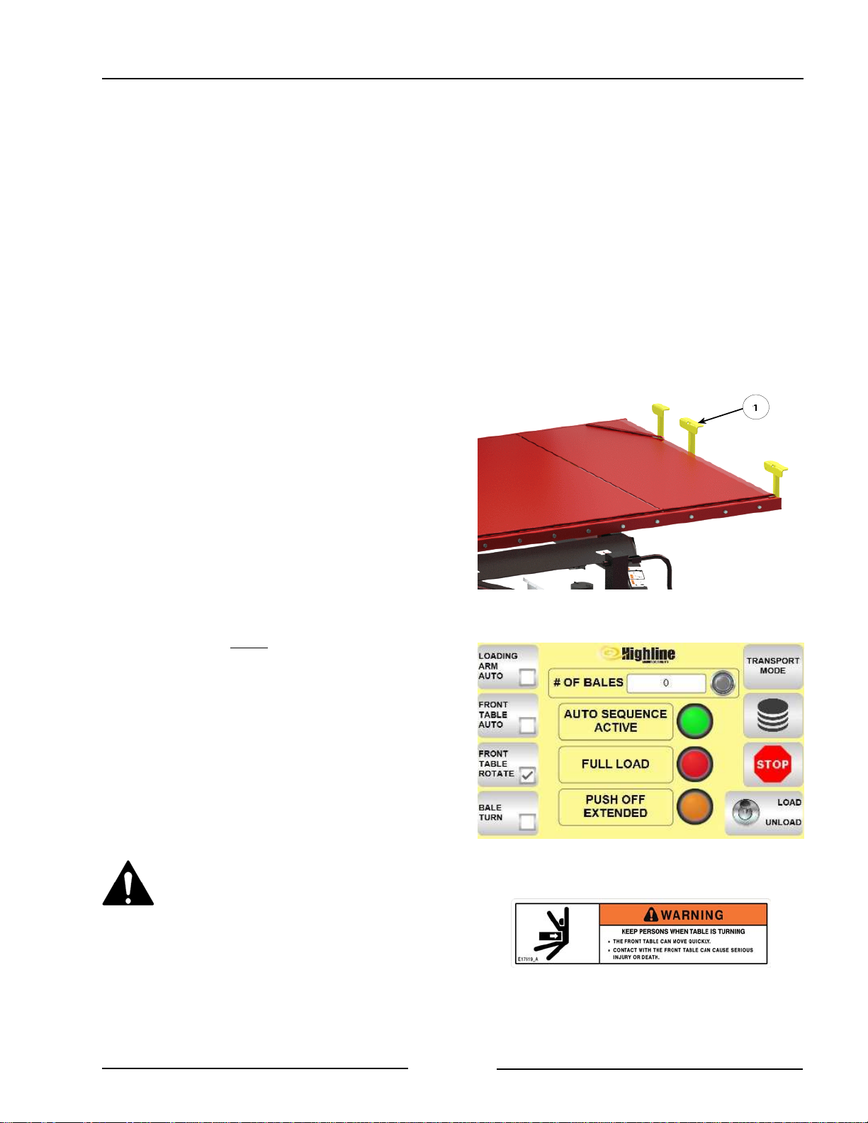
Section 5 - Operating the Bale Stacker
- On the joystick press the front table
up button to raise the table and move
the bales onto the rear table.
- The side racks will open as the
front table is lifted.
- Pause while lifting the front table to
allow the bales to move so they are
resting on the rollers of the rear table.
- As the bales are pushed onto the
rear table the bales on the table are
pushed back and the trolley will also
be pushed back.
Note: If the bales are hitting against the
side racks when being lifted,
adjust the bale stops (1) on the
front table.
- Loosen the bolts on the stops (1)
and move the stops as needed.
- Lower the front table.
FaStack 1200 Front Table Raise
Manual Control With Rotating Bales
- Lower the lift arm before raising the
front table.
- Ensure the Front Table Rotate on the
display is on.
- There should be a check mark in
the small box to indicate it is
turned on.
Stay clear of the table when
rotating. The front table can move
quickly. Contact with the front
table can cause serious injury or
death.
Adjust Front Table Stops
Turn On Front Table Rotate
218072C
219182
Page 5-11
Page 71
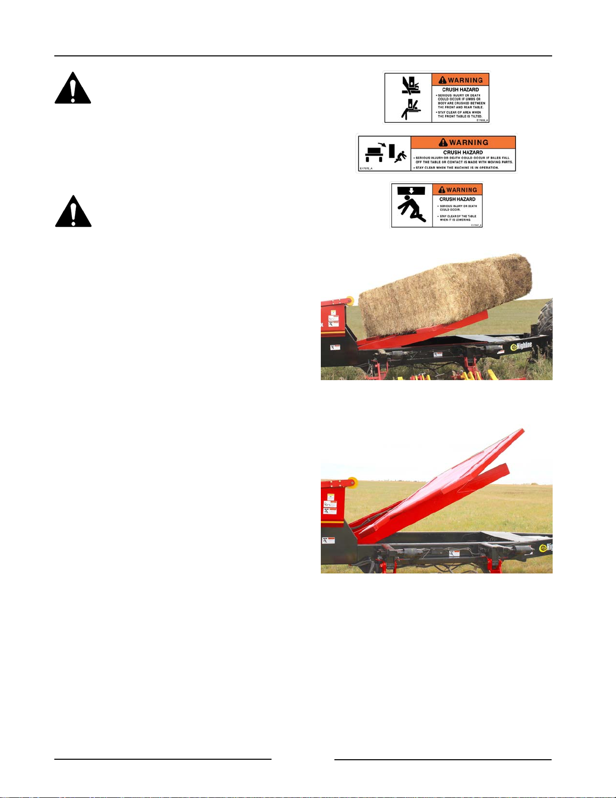
Section 5 - Operating the Bale Stacker
Stay clear when raising or
lowering the tables. Serious injury
or death could occur from contact
with the moving table. There is a
crushing hazard if limbs or body is
placed between the hitch and
table when the table deck is
lowered.
Stay clear when front table is
lifted because bales could fall.
- On the joystick press the front table
up button to raise the table.
- As the table rises the front table
will rotate.
- Fully raise the table and move the
bales onto the rear table.
- The side racks will open as the
front table is lifted.
- While lowering the front table it will
rotate to be ready for loading more
bales.
Table Will Rotate as Being Raised
Table will Rotate While Being Lowered
219049
218074
Page 5-12
Page 72
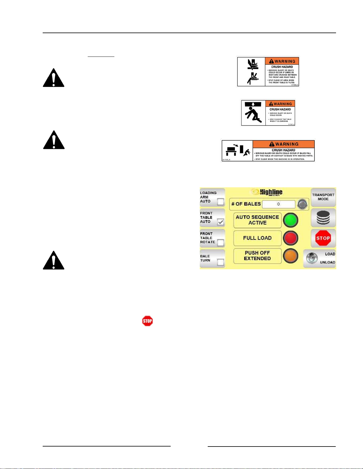
Section 5 - Operating the Bale Stacker
FaStack 1200 Front Table Raise
Auto Control Without Rotating the Bales
Stay clear when raising or
lowering the tables. Serious injury
or death could occur from contact
with the moving table. There is a
crushing hazard between the
hitch and table when the table
deck is lowered.
Stay clear when front table is
lifted because bales could fall.
- Lower the arm before lifting the front
table.
- Ensure the Front Table Rotate on the
display is off.
- Press the Front Table Auto to be on.
- There should be a check mark in
the small box to indicate it is
turned on.
Keep people clear of the
machine when in Auto mode.
Parts of the machine will move
without operator control and
move unexpectedly.
Note: The Auto function can be stopped
at anytime by pressing the
joystick button or the button.
- On the joystick press the Front Table
Up button to raise the table.
- The Auto Sequence Active light
will turn on.
- The front table will rise and the
side racks will open.
- The bales will be moved to the
rear table and the trolley will be
pushed back.
- The front table will lower.
- The side racks will close.
Front Table Auto - No Table Rotate
219183
Page 5-13
Page 73
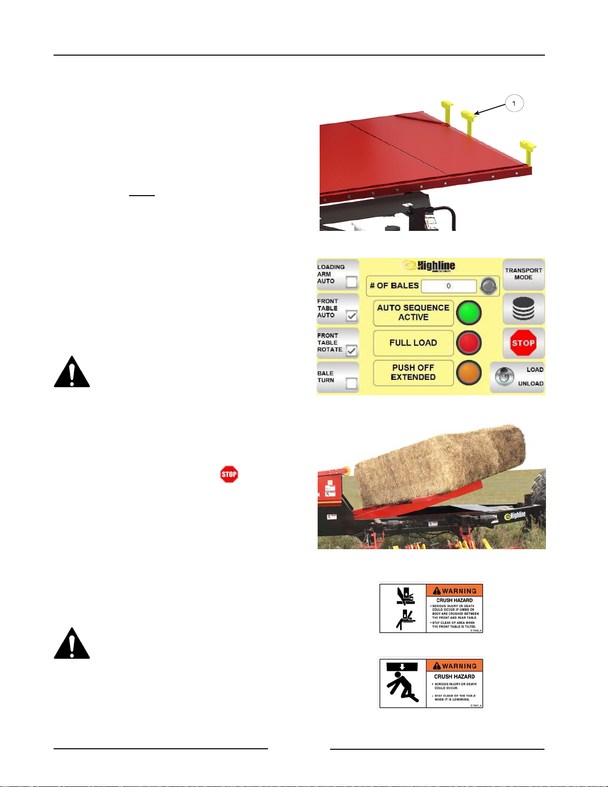
Section 5 - Operating the Bale Stacker
Note: If the bales are hitting against the
side racks when being lifted, adjust
the bale stops (1) on the front table.
- Loosen the bolts holding the
stops (1) and move the stops as
needed.
FaStack 1200 Front Table Raise
Auto Control With Rotating the Bales
- Ensure the Front Table Rotate on the
display is on.
- There should be a check mark in
the box to indicate it is turned on.
- Press the Front Table Auto to be on.
- There should be a check mark in
the small box to indicate it is
turned on.
Adjust Front Table Stops
218072C
Keep people clear of the
machine when in Auto mode.
Parts of the machine will move
without operator control and
move unexpectedly.
Note: The Auto function can be stopped
at anytime by pressing the
joystick button or the button.
- Lower the arm before lifting the front
table.
- On the joystick press the Front Table
Up button to raise the table.
- The Auto Sequence Active light
will turn on.
- The front table will rise and rotate.
The side racks will open.
Stay clear when raising or
lowering the tables. Serious injury
or death could occur from contact
with the moving table. There is a
crushing hazard between the
hitch and table when the table
deck is lowered.
Front Table Auto with Table Rotate
Table Will Rotate as Being Raised
219184
219049
Page 5-14
Page 74
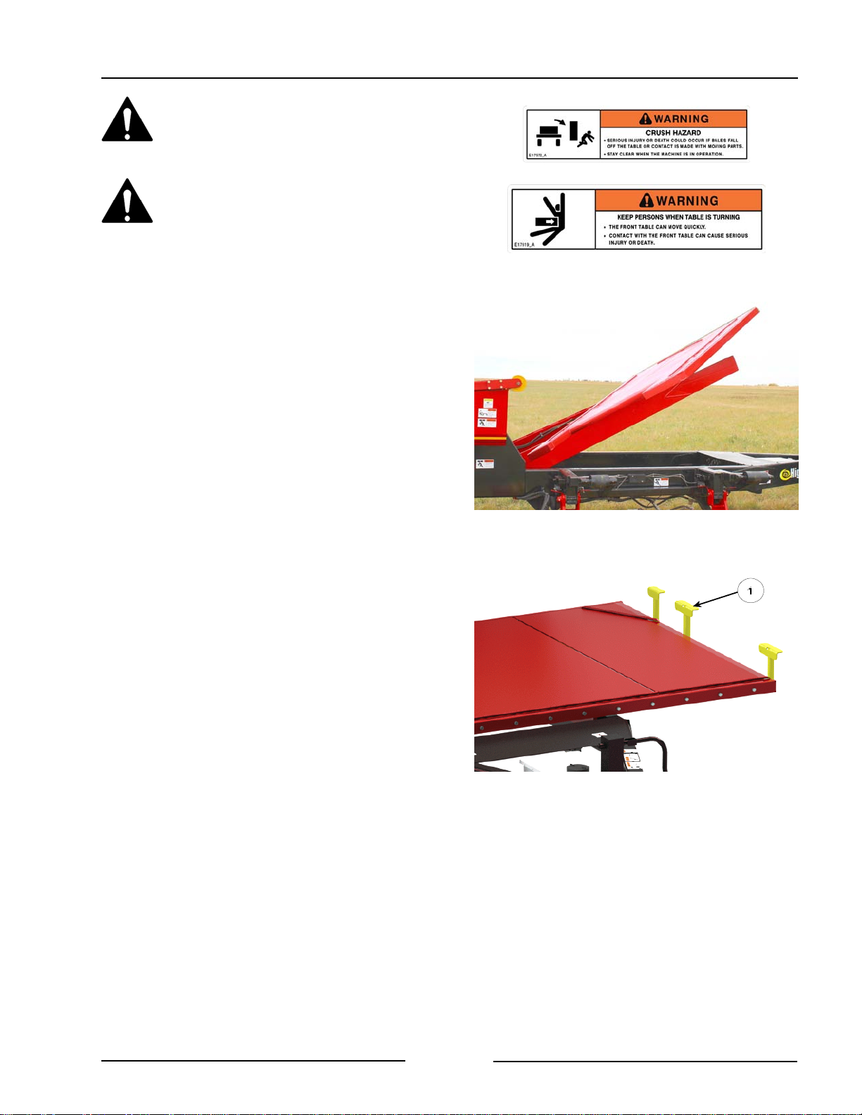
Section 5 - Operating the Bale Stacker
Stay clear when front table is
lifted because bales could fall.
Stay clear of the table when
turning. The front table can move
quickly. Contact with the front
table can cause serious injury or
death.
- The bales will be moved to the
rear table.
- The front table will then lower and
rotate.
Note: If the bales are hitting against the
side racks when being lifted,
adjust the bale stops (1) on the
front table.
Table will Rotate While Being Lowered
-
218074
- Loosen the bolts holding the
stops (1) and move the stops
as needed.
Page 5-15
Adjust Front Table Stops
218072C
Page 75
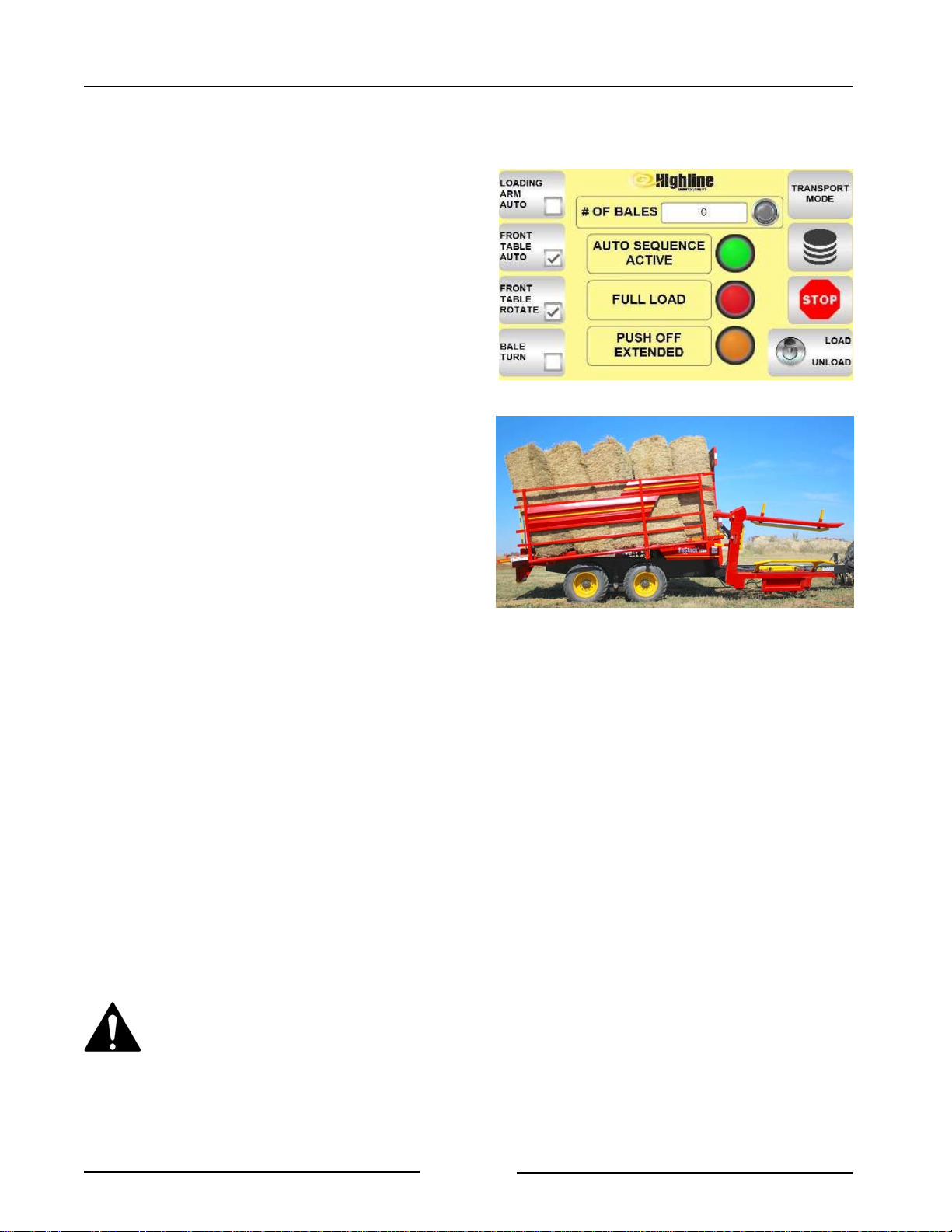
Section 5 - Operating the Bale Stacker
Rear Table Full Load
- When the rear table has a full load
the red light "Full Load" will come on
the display.
- Fully raise the front table.
- The front table against the
bales gives added stability
while traveling to the stacking
site.
- Drive to the stacking storage site.
- Push the Loading Arm Auto +
Transport Mode buttons to move
the lift arm to the raised position.
- The Transport Mode will blink
a red color.
- Ensure the side racks are closed.
- Adjust ground speed to suit the
terrain to maintain load stability.
If traveling on roadways:
- Ensure the bales are secure in the
stacker.
- Install the load arm transport locks.
- Ensure the clearance lights and SMV
are visible.
Full Load Indicator Light
Drive to the Stacking Site - Front Table Raised
219184
217181
- Ensure the lights are operating.
- Consult the local road regulations
regarding securing the load and road
travel. Follow all the applicable
regulations.
Do not exceed 6 mph (10 km/h)
when fully loaded.
Note: Transport speed will need to
be lower when heavier bales
are loaded on the stacker.
Page 5-16
Page 76
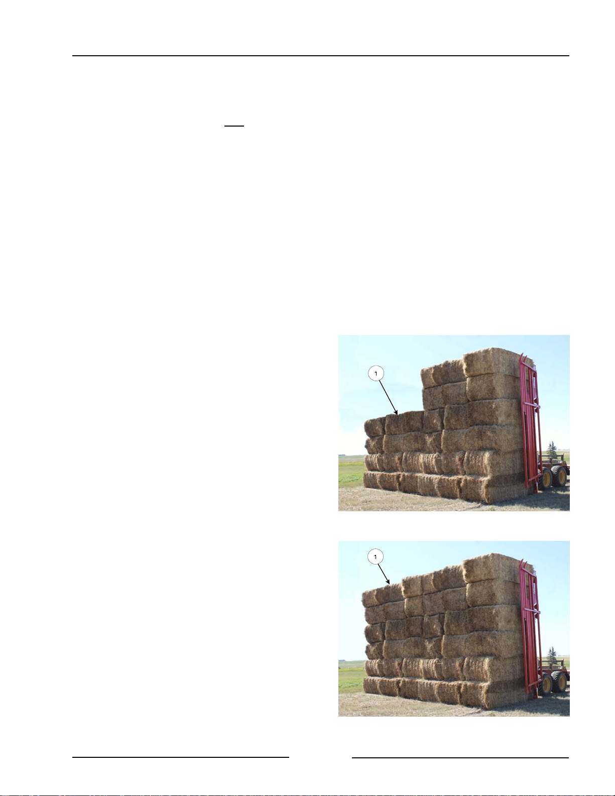
Section 5 - Operating the Bale Stacker
Recommended Procedures for Starting A
Bale Stack with:
! FaStack 1800
! FaStack 1200 Bales Not Rotated
Note: On FaStack 1200 this is only
for bales that are loaded with
the 4' side of the bale resting
on the table.
1. The stacking location must be free of
mole hills, rough ground and debris.
- The location must be level or at a
slight incline.
- If the stacking location has a
slight incline, unload with the
tractor pointed uphill.
- When the tractor is pointed
uphill, gravity will help to keep
the top of the stack in place
and prevent bales from falling
forward as the tractor pulls
away or between loads.
2. Position the stacker to unload the first
load (1).
Note: It may be helpful to start by
placing a partial load ("stair
step") to give stability to the
stack as larger loads are
stacked.
- Keep the side racks closed while
raising the stack.
- Press Unload button on the display.
- Raise the rear table so that it is
vertical or slightly past vertical.
- The end of the forks must be on
the ground.
- Open the side racks.
Optional Partial First Load For Stack Stability
218077-1C
- Slowly pull the tractor away from the
stack.
Page 5-17
Full Load as First Load
218077C2
Page 77
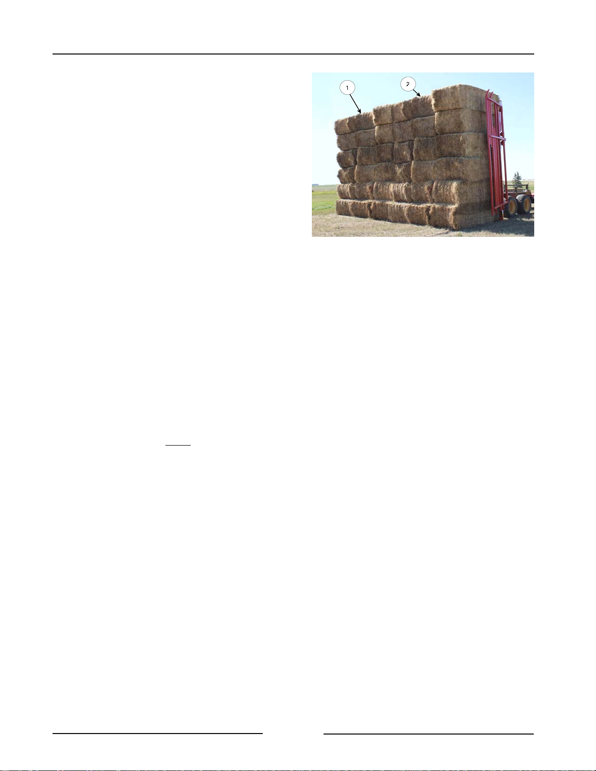
Section 5 - Operating the Bale Stacker
3. For the second load position (2) the
stacker beside the previous stack (1).
- Position the stacker so that when
the rear table is upright the stack
(2) will be close to the previous
stack and the bales in line.
- Raise the rear table so that it is
vertical or slightly past vertical.
- The end of the forks must be on
the ground.
- Open the side racks.
- Slowly pull the tractor away from the
stack.
Second Load Beside Previous Stack
218077C
4. Additional loads of bales can be placed
beside or up against the stack.
Recommended Procedures for Starting A
Bale Stack with:
! FaStack 1200 With Bales Rotated
1. The stacking location must be free of
mole hills, rough ground and debris.
- The location must be level or at a
slight incline.
- If the stacking location has a
slight incline, unload with the
tractor pointed uphill.
- When the tractor is pointed
uphill, gravity will help to keep
the top of the stack in place
and prevent bales from falling
forward as the tractor pulls
away or between loads.
Page 5-18
Page 78
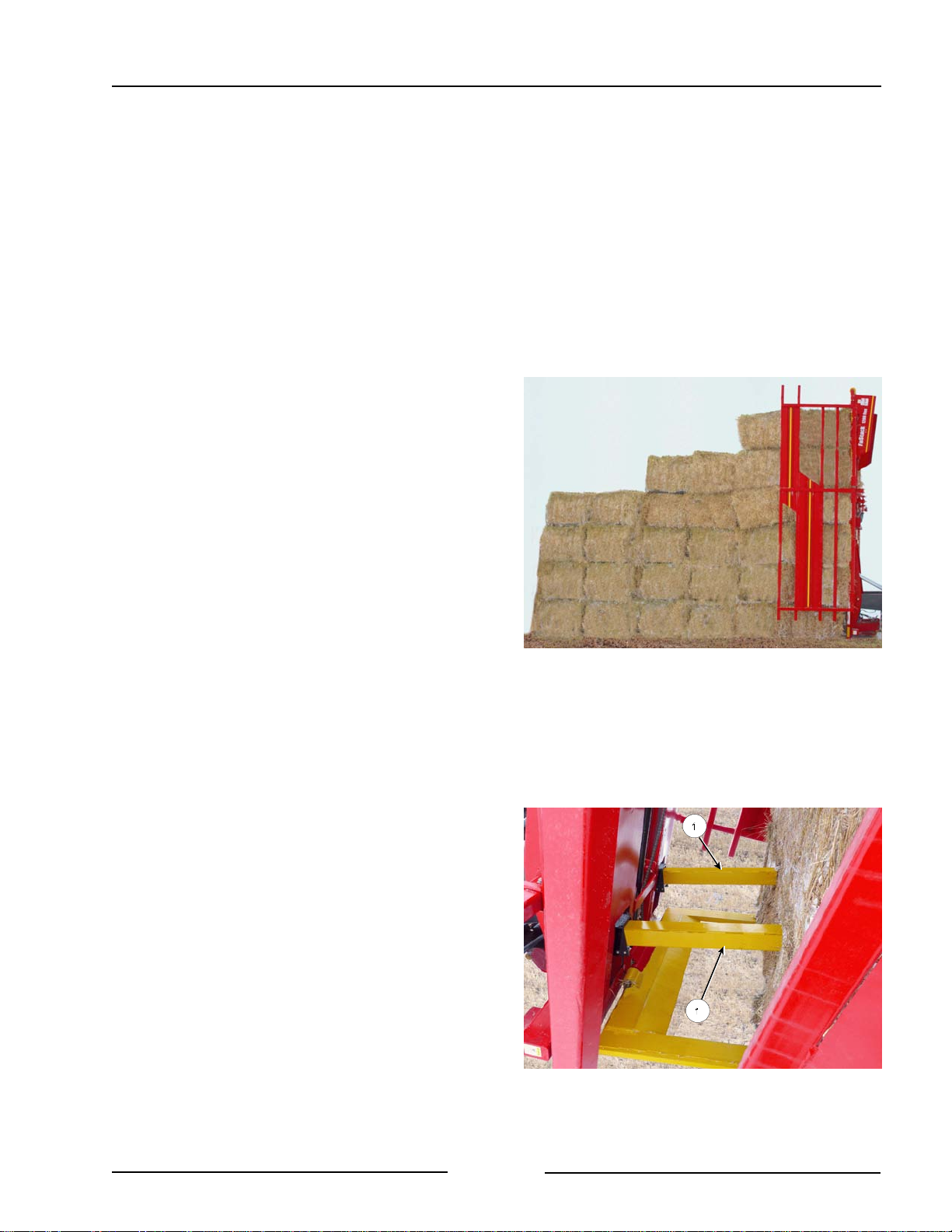
Section 5 - Operating the Bale Stacker
2. Begin the stack in a "stair step" method
by stacking partial loads of a reduced
height.
- This method helps to create stability
for additional bale loads and to aid in
the unloading of more bales.
- When stacking bales of 3' high (ex.
3'x4' bales being stacked on-string),
it is recommended to make the first
stack 4 bales high, the second stack
5 bales high, and the third stack 6
bales high.
3. Place the stacker in position to unload
the first stack of 4 bales.
- Press Unload button on the display.
- Raise the rear table so that it is
vertical or slightly past vertical.
- The end of the forks must be on
the ground.
- If the machine is equipped with side
racks, keep them closed while
raising.
- Open the side racks when the table is
fully raised.
- Use the joystick button to extend the
pushoffs (1) to push the stack to near
the end of the forks.
- Slowly pull the tractor away.
- Retract the pushoffs.
4. For the second load of 5 bales, position
the stacker with the tractor facing away
from the stack and the tractor and
stacker as straight as possible.
1200 Flex Rotated Bales - Create Staircase for
Stability
Extend Push Off Cylinders
218076C
218204
- If on an incline, the tractor should be
facing uphill whenever possible.
Page 5-19
Page 79
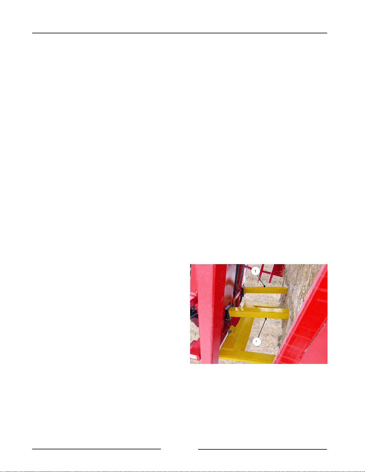
Section 5 - Operating the Bale Stacker
5. Raise the rear table to around 45
degrees from the ground.
6. Back up the tractor until it is possible to
see the bottom corners of the previously
placed stack. This can be used as a
guide to align the stacks.
7. Continue raising the rear table until it is
raised to around 60 degrees from the
ground.
8. Continue backing up until gentle contact
is made with the previous placed stack.
- The can be accomplished by
clutching the tractor and rolling back
into the stack.
Note: When unloading the second stack
use caution to avoid knocking
over the first stack.
9. Continue raising the rear table until it is
90 degrees with the ground or slightly
over.
- Do not allow the tractor to creep
forward while raising the table.
10. Keep foot on the tractor brakes.
11. Extend the pushoffs (1).
12. Pull the tractor ahead very slowly
while extending the pushoffs until the
forks are out from under the stack.
If stacking on level ground or with the tractor
pointed slightly downhill:
- The rear table can be extended over
90 degrees in order to compress the
top of the stack. This helps in
preventing the stack from falling
forward when pulling away.
Extend Push Off Cylinders
218204
Page 5-20
Page 80
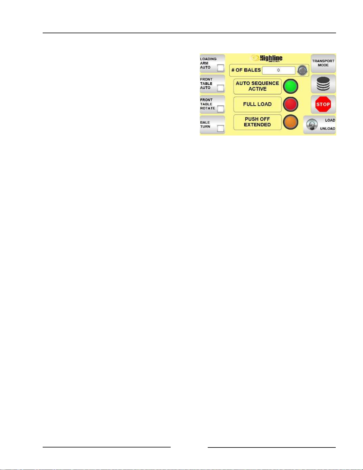
Section 5 - Operating the Bale Stacker
13. Fully retract the pushoffs until the
Push Off Extended light on the
display goes out.
- The recommended procedure is to
fully retract the pushoffs before
pulling the tractor away from the
stack.
- Watch the top of the stack for
falling bales.
14. Drive the tractor away from the stack.
15. Finishing the stack by "stair stepping"
the last loads that are placed in a
stack.
- When stacking bales that are 3'
high (ex. 3'x4' bales being
stacked on-string), a typical
procedure is to make the second
last stack 5 bales high and the
last stack 4 bales high.
Retract Push Off Cylinders Until Light Out
219181
Page 5-21
Page 81
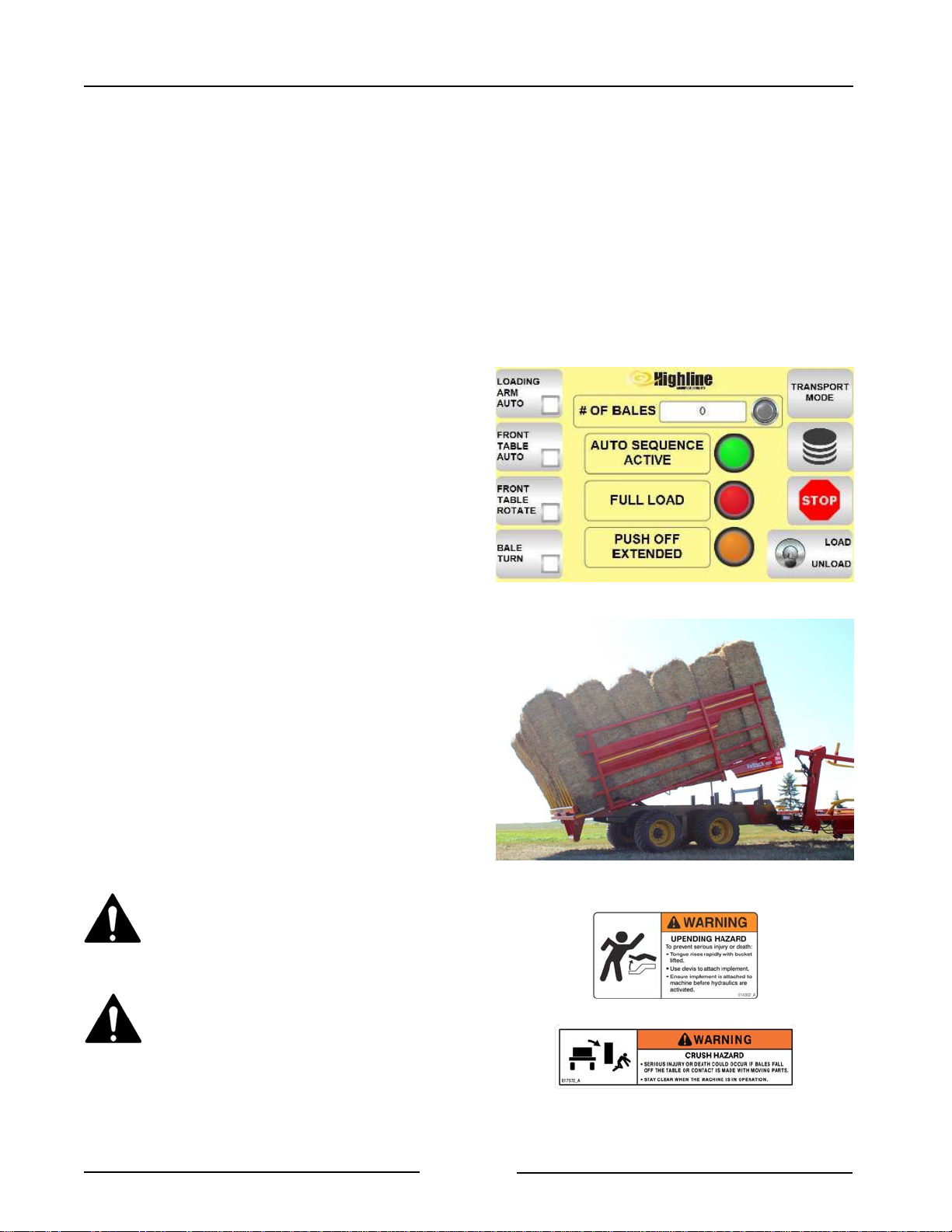
Section 5 - Operating the Bale Stacker
Unloading Bales
1. Lower the lift arm to be clear of the front
table.
- If Transport Mode + Loading Arm
Auto is on, then push the Transport
Mode.
- The lift arm will lower to the ready
position and the Transport Mode
will stop blinking.
2. Fully lower the front table.
3. Position the stacker for unloading using
the recommended stacking procedure
listed above.
- See pages 5-17 and 5-18.
4. Select Unload on the display.
- This setting will cause the joystick
buttons to operate in the Unload
mode as shown on the joystick
decal.
5. Open the side racks a small amount.
- Use the joystick buttons on the
1800.
- Use the joystick buttons on the
1200 Flex (if the optional side
racks are present).
6. Use the joystick button to begin to raise
the rear table.
Do not disconnect the hitch when
the rear table is lifted. There is
an upending hazard at the hitch
when the rear table is lifted.
Select Unload on the Display
Begin to Raise the Rear Table
219181
217183
Ensure the area is clear of
people or animals before
unloading. The bales may fall
and could result in death or
serious injury.
Page 5-22
Page 82
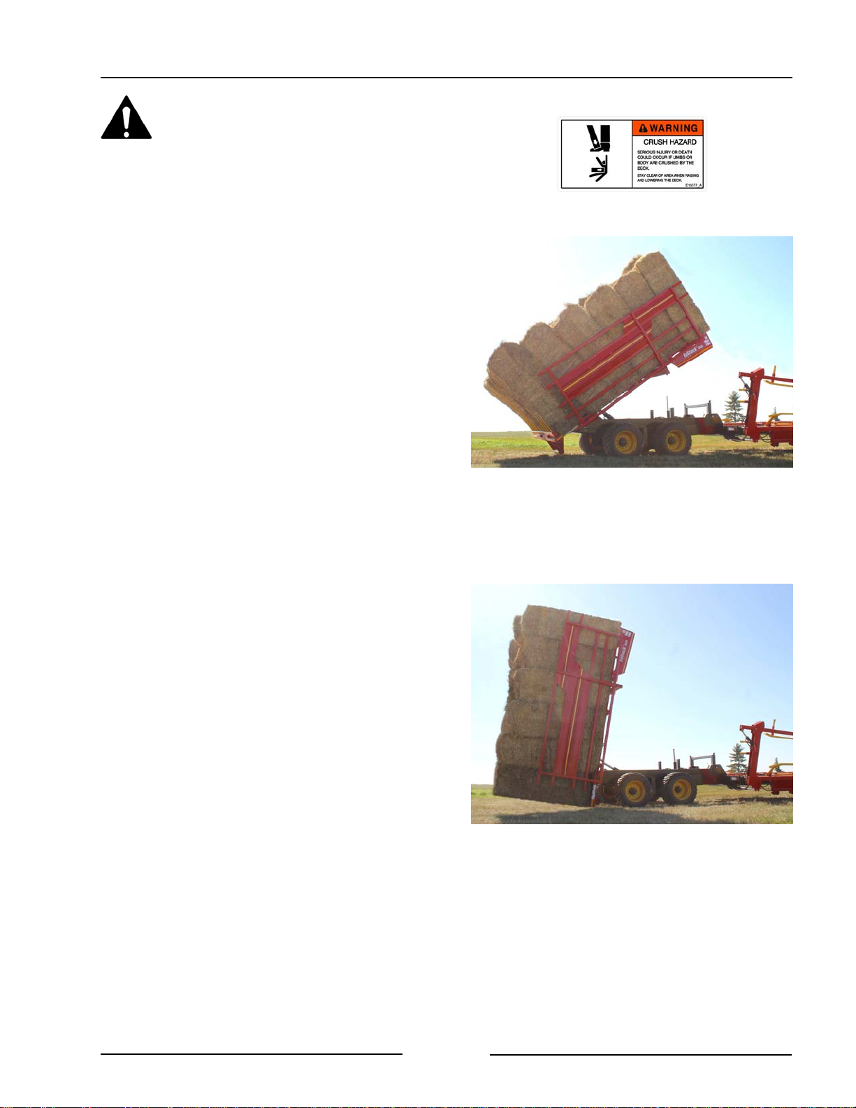
Section 5 - Operating the Bale Stacker
Stay clear of the rear table when
raising. There is a crushing
hazard if limbs or body is placed
between the table and ground or
surrounding objects when the
table is raised.
7. Stop raising the table when the bales
start to slide.
- Often the trolley is not entirely at
the back of the table and the load
will move further back on the
table as it rises.
- Open the side racks slightly to
allow the bales to settle to the
bottom of the table.
- This is especially important
when unloading partial loads.
Raise Table, Let Bales Slide, Open Side Rails
217182
- Tighten the side racks.
8. Continue raising the table again with
pauses while raising.
Note: As the rear table approaches
the upright position quite a bit of
momentum can develop. The
momentum can cause the top of the
stack to pick up speed.
- If there is no pausing to allow the
bales to settle it is possible for the
stack to continue to go over and
fall.
- Pausing while raising will allow
the bales to settle and also
reduces the momentum.
Use Pauses While Lifting the Table
217184
- Pausing while raising also
ensures that the bales will all be
stacked together.
Page 5-23
Page 83
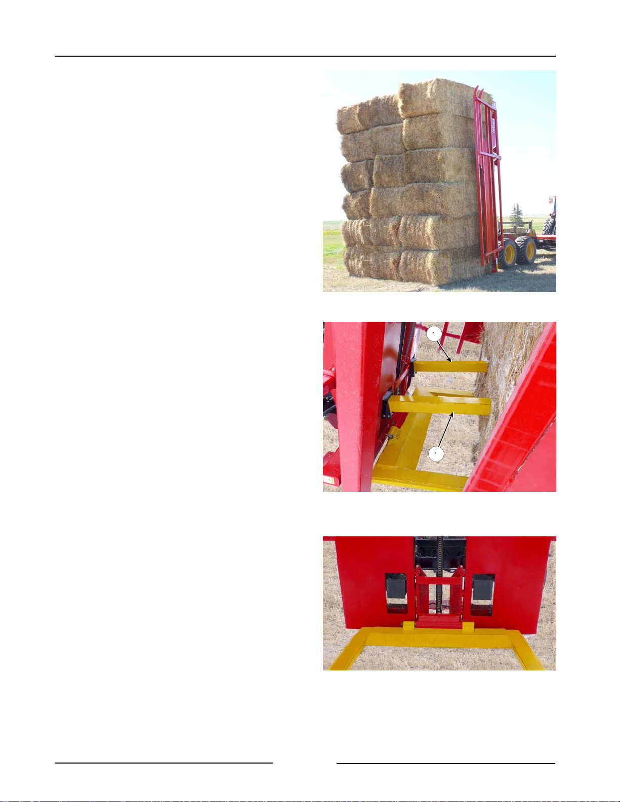
Section 5 - Operating the Bale Stacker
9. Lift the rear table to the fully raised
position.
10. Open the side racks when the table is
raised.
- If unloading beside a stack, only
open the racks a small amount.
11. Slowly drive forward as the bales are
unloading.
- On the FaStack 1200 Flex
activate the pushoffs (1) to help
push the bales off the forks.
Raise Table, Open Side Racks
217069
- Push the joystick button to
extend the pushoffs (1) drive
forward slowly.
- Retract the pushoffs (1) while
driving away.
Activate the Push offs to Unload Bales
(1200 Flex)
219051
Page 5-24
FaStack 1200 Retract Push Off Cylinders
219052
Page 84
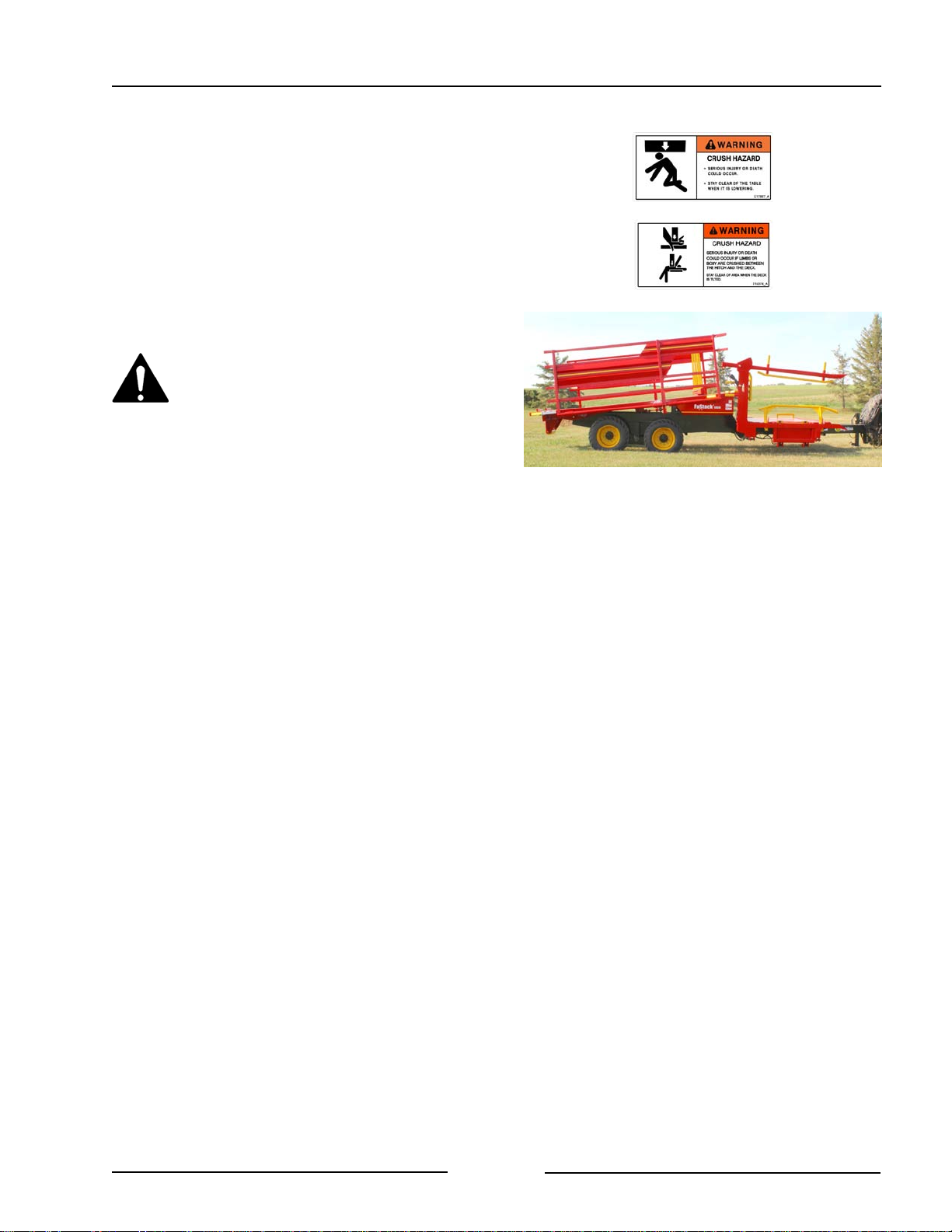
Section 5 - Operating the Bale Stacker
12. When the bales are unloaded and
clear of the machine, use the joystick
button to lower the table completely.
Note: On the 1200 Flex, if the
joystick button to lower the
rear table is pushed while the
pushoffs are extended then
the pushoffs will retract before
the table is able to lower.
Stay clear when raising or
lowering the rear table.
Serious injury or death could
occur from crushing or pinching
by the table.
Lower The Table
217185
13. Use the joystick button to close the
side racks.
14. Push the joystick button to bring the
trolley forward in preparation for
loading more bales.
Page 5-25
Page 85

Section 5 - Operating the Bale Stacker
This Page Left Blank
Page 5-26
Page 86
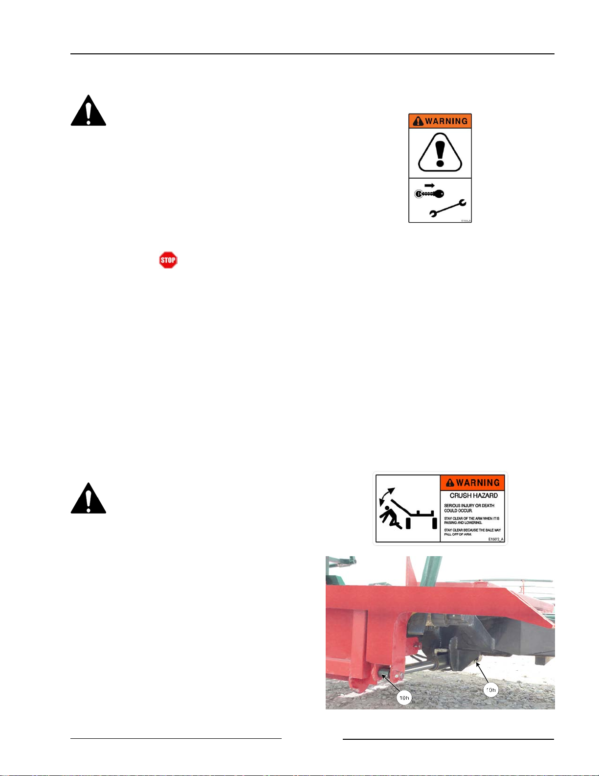
Section 6 - Maintaining the Bale Stacker
6.0 Maintaining the Bale Stacker
Shutdown Procedure
For your safety and the safety of
others, this procedure must be
followed before dismounting from
the tractor for repairing, servicing,
cleaning or lubricating the bale
stacker.
Step 1: Reduce the engine speed to idle.
Step 2: Fully lower bale lift arm.
Step 3: Touch button on the display.
Step 4: Disengage hydraulic lever.
Step 5: Set the tractor park brake.
Step 6: Shut off tractor engine and remove
the key.
Step 7: Relieve hydraulic pressure and
disconnect hydraulic hoses.
Lubrication
Lubricate all grease fittings with a quality
lithium complex, extreme pressure NLGI
Grade 2 grease.
Grease the Lift Arm Every 10 Hours
Install the transport lock when
the lift arm is raised. A raised
lift arm could lower which could
result in death or serious injury.
! Main Lift Arm Cylinders
- 2 cylinders with 2 points each.
Page 6-1
Grease Both Main Lift Arm Cylinders
217089C
Page 87
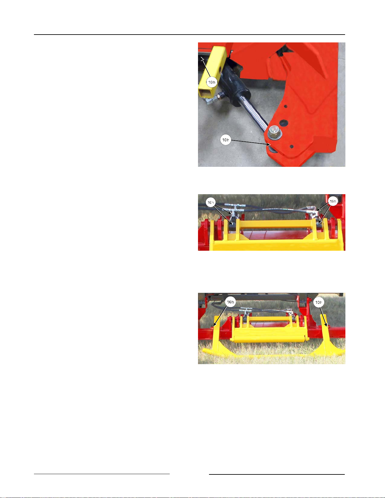
Section 6 - Maintaining the Bale Stacker
! Lift Clamp Arm and Cylinder
- 2 points on the cylinder.
! Grease the bale turn cylinders
- 2 cylinders with 2 points each.
! Grease the bale support arm pivots
- 2 points on the arm.
Grease Lift Clamp Arm and Cylinder
Grease the Bale Turn Cylinders
219041-2C
217189-2C2
Page 6-2
Grease the Bale Support Arm Pivots
217189C
Page 88
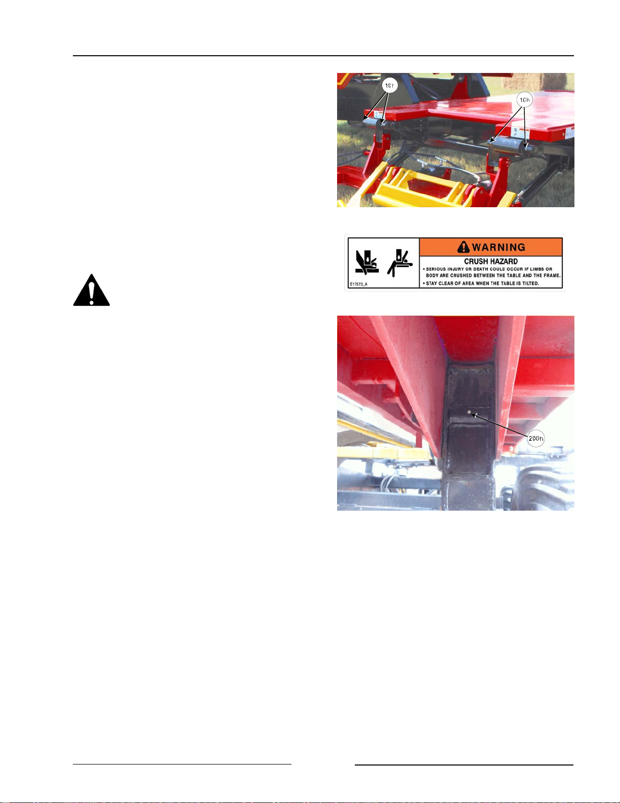
Section 6 - Maintaining the Bale Stacker
! Grease the rollers at the front table
- 2 rollers with 2 points each.
Grease Every 200 Hours
Do not raise the tables to do the
greasing. A raised table could
lower which could result in death
or serious injury.
! Grease the rear table pivots at the back
of the machine
- 1 point on each side of table
Grease Rollers Under Front Table
217190C
Page 6-3
Grease Rear Table Pivots
(Right Side Shown)
219053C
Page 89
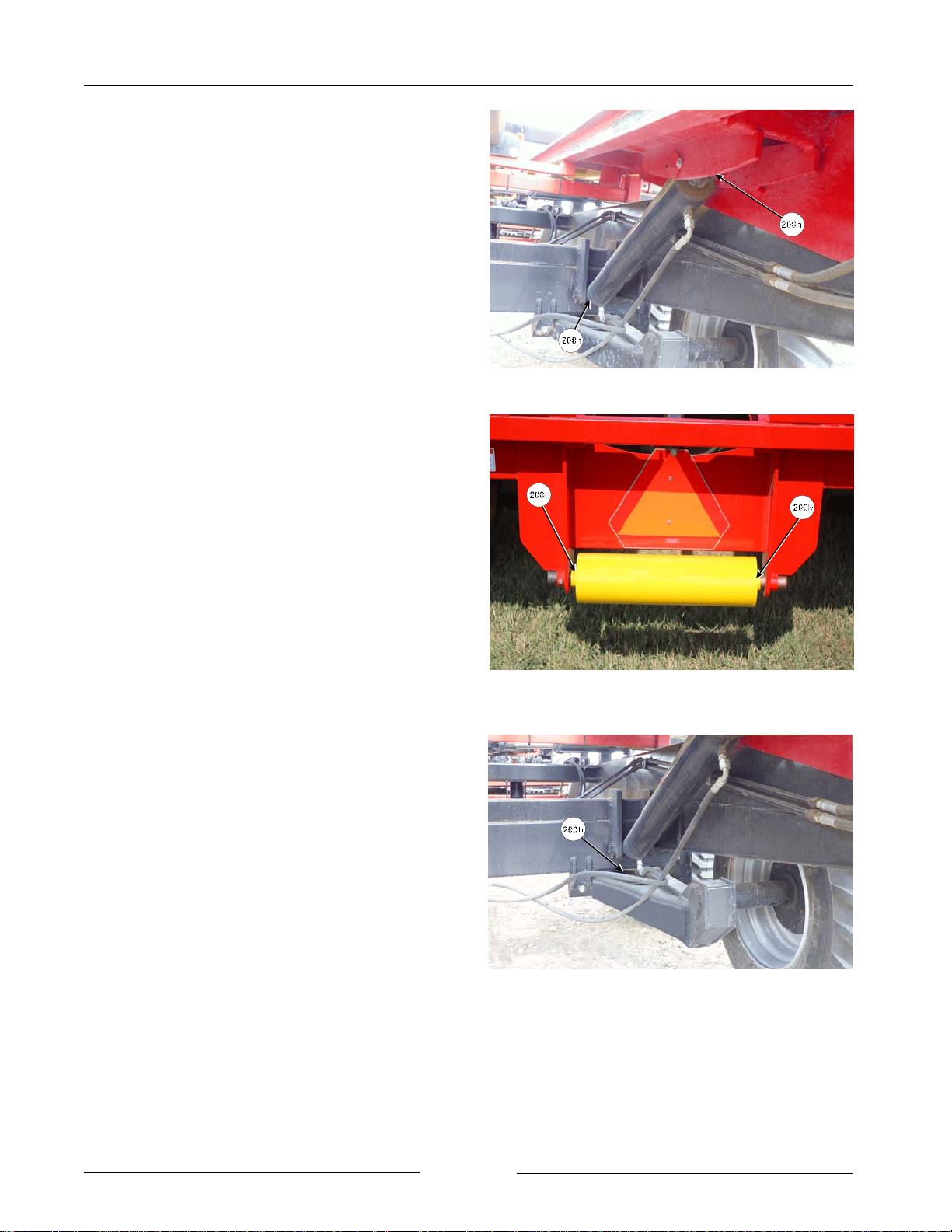
Section 6 - Maintaining the Bale Stacker
! Grease the rear table cylinders
- 2 cylinders with 2 points each
! Grease the rear table roller
- 1 roller with 2 points
! Grease the axle walking beams
- 2 axles with 1 point each
Grease Rear Table Cylinders
Grease Rear Table Rear Roller
217123C
217191C
Page 6-4
Grease the Axle Walking Beams
217125C
Page 90
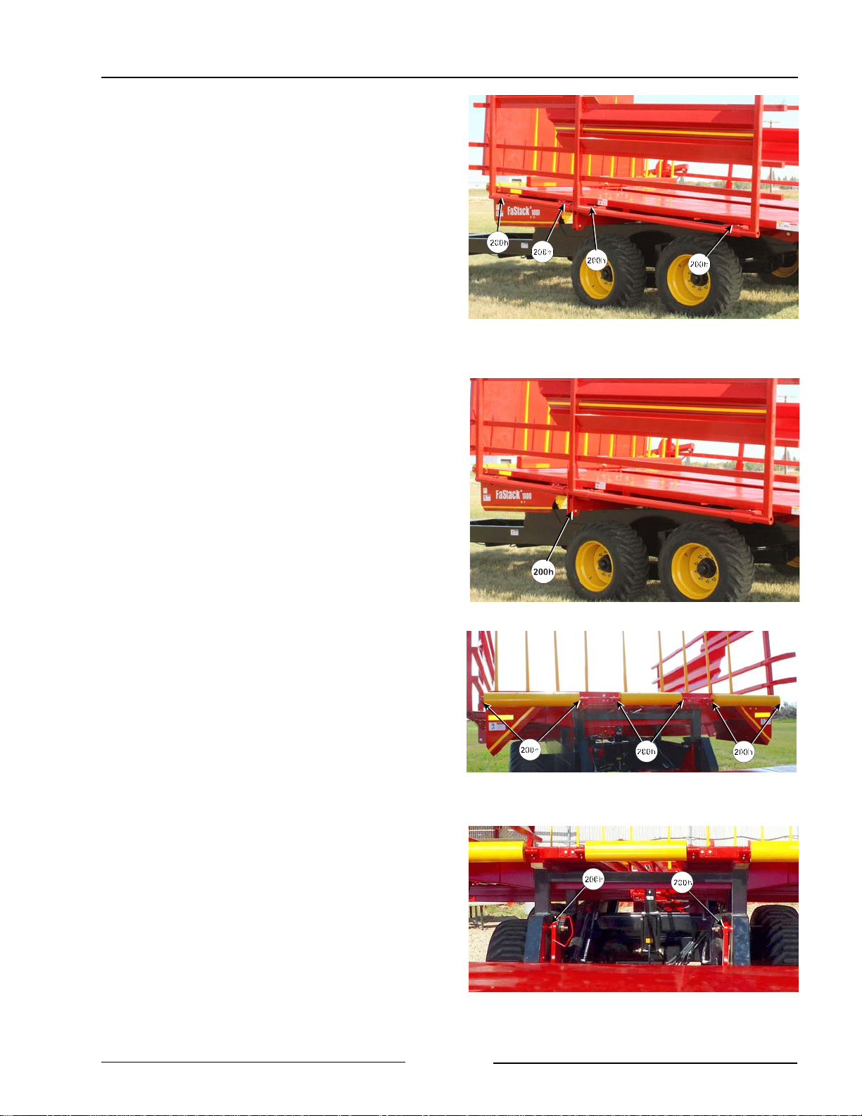
Section 6 - Maintaining the Bale Stacker
! Grease the side rails on each side of the
machine
- 4 points on each side rail
! Grease the side rail linkage on each side
of the machine
- 1 point on linkage on each side
! Grease the front rollers on the rear table
- 2 points on each roller
- 3 rollers on FaStack 1800
- 2 rollers on FaStack 1200
Grease the Side Rails
Grease the Side Rail Linkage
217192C
217192C2
! Grease the front table pivots
- 1 point on each pivot
Grease Front Rollers on Rear Table
Page 6-5
Grease Front Table Pivots
217193C
217194C
Page 91
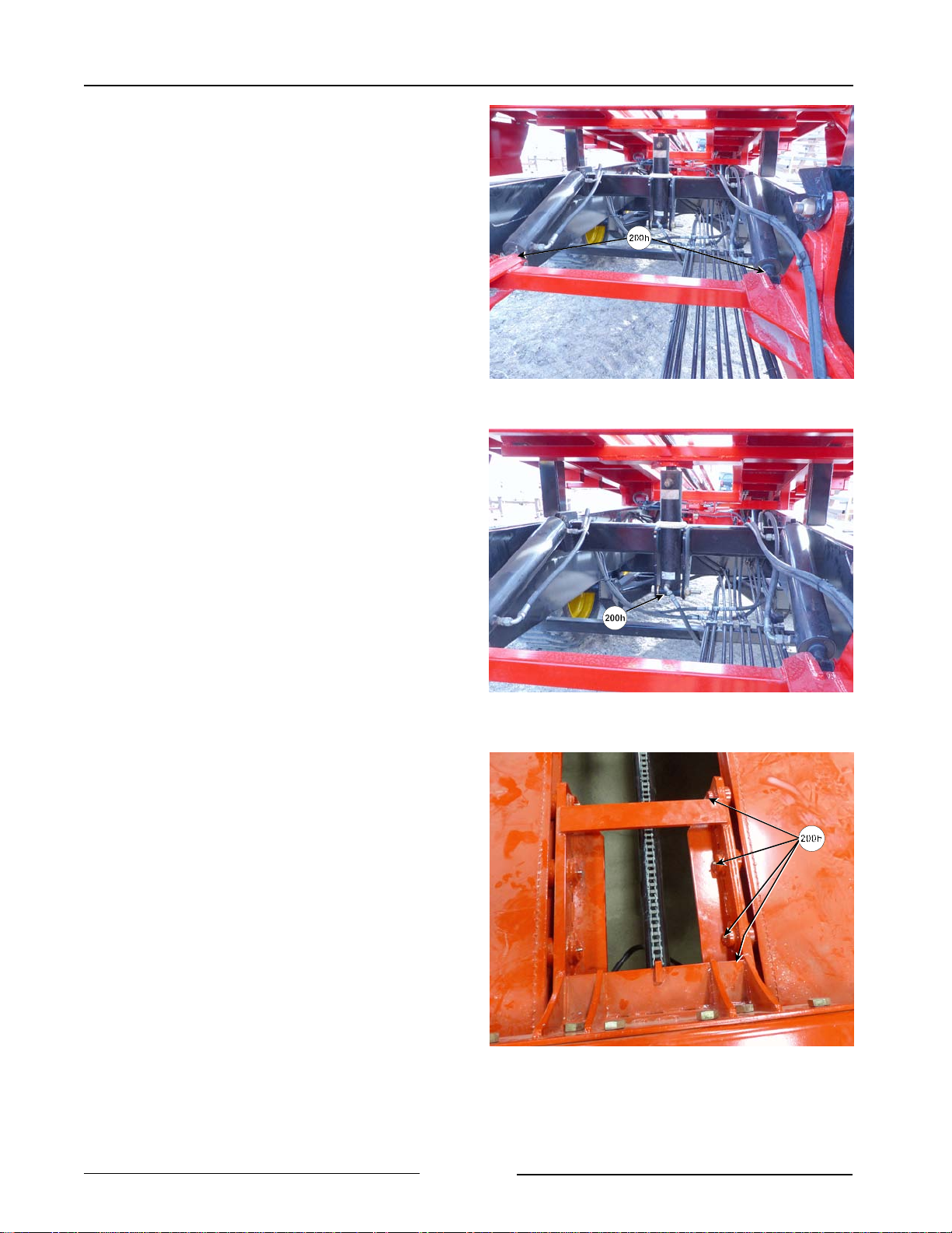
Section 6 - Maintaining the Bale Stacker
! Grease the front table cylinders
- 2 cylinders.
- 1 point on each cylinder.
! Grease the rear table boost cylinder
- 1 point.
! Grease the trolley carriage
- 8 points on the carriage
Grease Front Table Cylinders
Grease the Rear Table Boost Cylinder
217195C
217196C
- 4 points on each side of the
carriage
Page 6-6
Grease the Trolley Carriage
217197C
Page 92
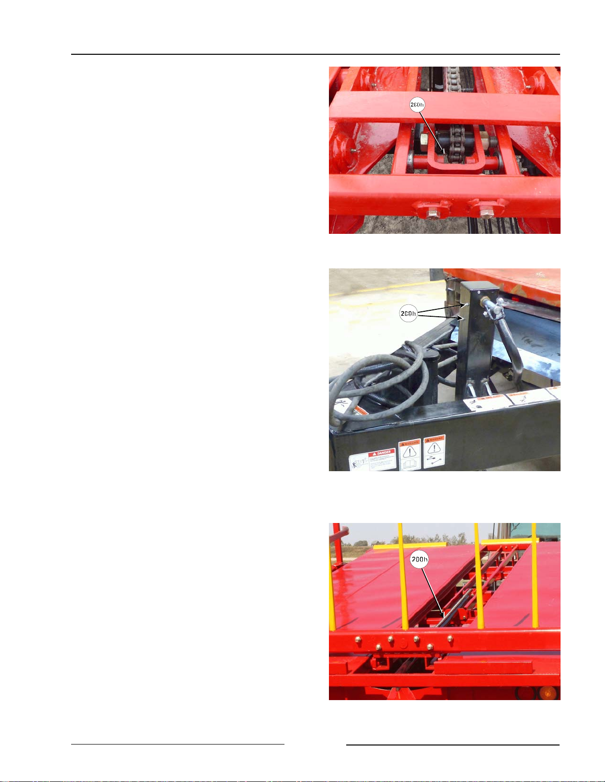
Section 6 - Maintaining the Bale Stacker
! Grease the trolley sprocket
- 1 point.
! Grease the hitch jack
- 2 points.
Grease the Trolley Sprocket
Grease the Hitch Jack
217198C
219054C
! Lubricate the trolley chain with a quality
chain oil.
Page 6-7
Lubricate the Trolley Chain
217199C
Page 93
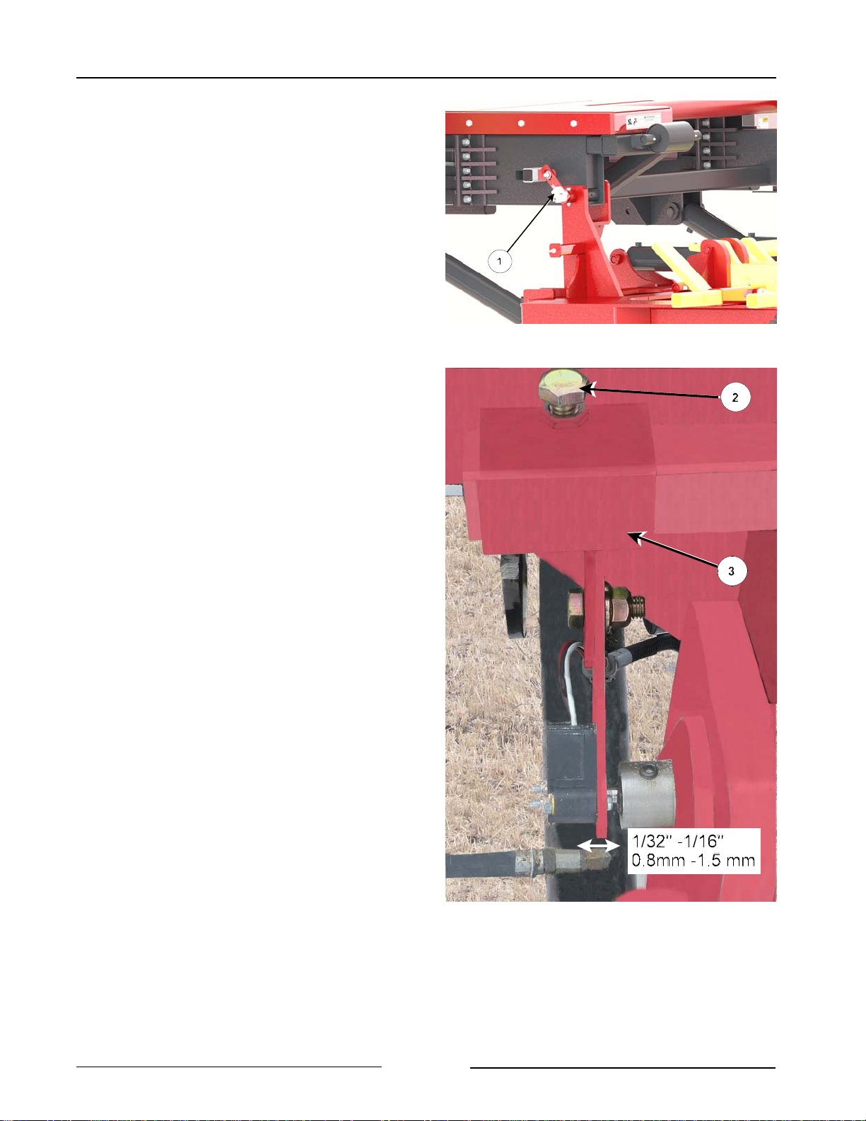
Section 6 - Maintaining the Bale Stacker
Check the Lift Arm Rotation Sensor
- Visually inspect rotation sensor (1)
mounted on the rear of the lift arm.
- Check that the sensor (1) is in good
condition.
- Check that the area around the
sensor is free from debris.
- Check that the electrical connector is
tight.
- Check that the sensor can be moved
back and forth along the shaft.
- The movement along the shaft
should be 1/32" to 1/16" (0.8 mm -
1.5 mm).
- This movement will prevent
any damage that might be
caused by movement of the lift
arm.
Check the Condition of the Rotation Sensor
218045C
- To adjust the movement loosen
the bolt (2) holding the slide tube
(3).
- Move the tube to allow for the
sensor movement of 1/32" to
1/16" (0.8 mm - 1.5 mm)
- Tighten the bolt on the sliding
tube.
Check the Condition of the Proximity
Sensors
Location of the switches:
- Retract on the pushoffs
- Flipper on the lift arm
- Full load sensor (trolley)
- Check that they are free of debris and
the wiring is in good condition.
Rotary Sensor Movement on Arm Shaft
219055-1C
Page 6-8
Page 94
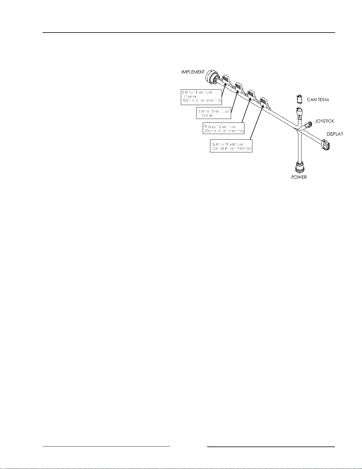
Section 6 - Maintaining the Bale Stacker
Replacing An Electrical Fuse
The fuses are located in the tractor cable.
The fuse size is located on the fuse
holder. The fuses and what they protect
are indicated in the diagram.
Visually Inspect Hydraul i c
Hoses/Fittings
Shut down the machine and replace the
hydraulic hose assembly if any of the
following conditions exist:
Fuses In Tractor Cable
43543_B2C
- Fitting slippage on hose.
- Damaged, cracked, cut or abraded
cover (any reinforcement exposed).
- Hard, stiff, heat cracked or charred
hose.
- Cracked, damaged or badly corroded
fittings.
- Leaks at fitting or in hose.
- Kinked, crushed, flattened or twisted
hose.
- Blistered, soft, degraded or loose
cover.
Avoid Machine Damage If Welding
Disconnect all electrical connections before
welding on the machine. Attach the ground
cable of the welder as close as possible to
the part being welded.
Protect hoses during welding as weld splatter
may burn a hole or weaken the hose allowing
the loss of oil.
Page 6-9
Page 95
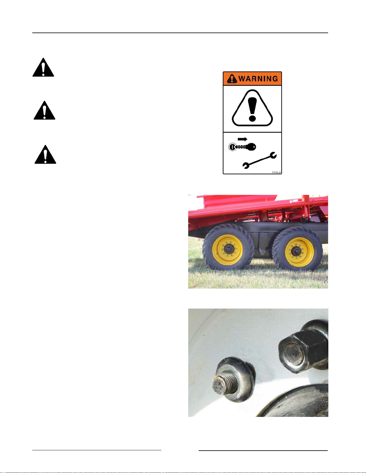
Section 6 - Maintaining the Bale Stacker
Tire Changing Procedure
Before beginning, make sure the
tractor is turned off and the
parking brake is set.
Securely block the bale stacker
before any work is done around or
under the machine.
Relieve hydraulic pressure and
disconnect the hydraulic hoses.
Note: Before beginning to change a tire,
lower the lift arm, lower the front
table and lower the rear table.
1. Hitch the bale stacker to the tractor.
2. Block the bale stacker tires on the
opposite side to prevent movement of the
bale stacker.
3. Place a jack under the spindle tube of the
tire to be changed.
4. Lift the machine for sufficient clearance to
remove the tire
5. Put the new tire in place.
- Ensure that the flat portion of the
wheel stud washer is against the
wheel rim.
6. Fasten the tire with the lug nuts.
- Torque the lug nuts to 170 lb-ft
(230 Nm).
Jack Under Spindle Tube to Change Tire
217200
Tire Pressure
Keep tires inflated to 40 psi (276 kPa).
Tire damage may occur if under inflated.
Flat of Washer Against Rim, Torque the Nuts
Page 6-10
217100
Page 96
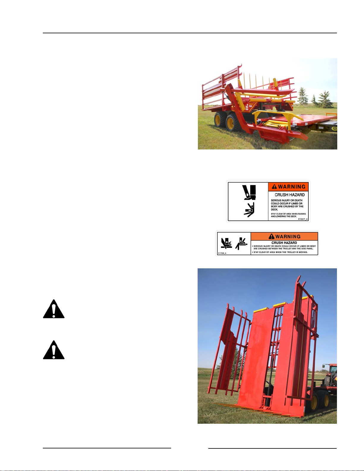
Section 7 - Storing the Bale Stacker
7.0 STORING THE BALE STACKER
1. Clean all the debris off the bale stacker.
2. Lubricate all bale stacker grease points
(See Section 6).
3. Lubricate the bale trolley chain to keep it
from weather exposure.
4. Tighten all bolts to the recommended
torque.
5. Check the bale stacker for worn and
damaged parts. Replace as needed.
6. Touch-up the paint to prevent rusting.
7. Park the bale stacker on level ground.
8. Raise the rear table to make the trolley
drop so the cylinder rod is not exposed to
the weather.
- Touch the Unload button on the
display.
- Use the joystick to raise the rear
table.
There is a crushing hazard if limbs
or body are placed between the
deck and ground or surrounding
objects when the deck is raised.
Park on Level Ground
217148
There is a crushing hazard if limbs
or body is placed between the
trolley and side panels.
Page 7-1
Raise Rear Table To Drop Trolley
218075
Page 97
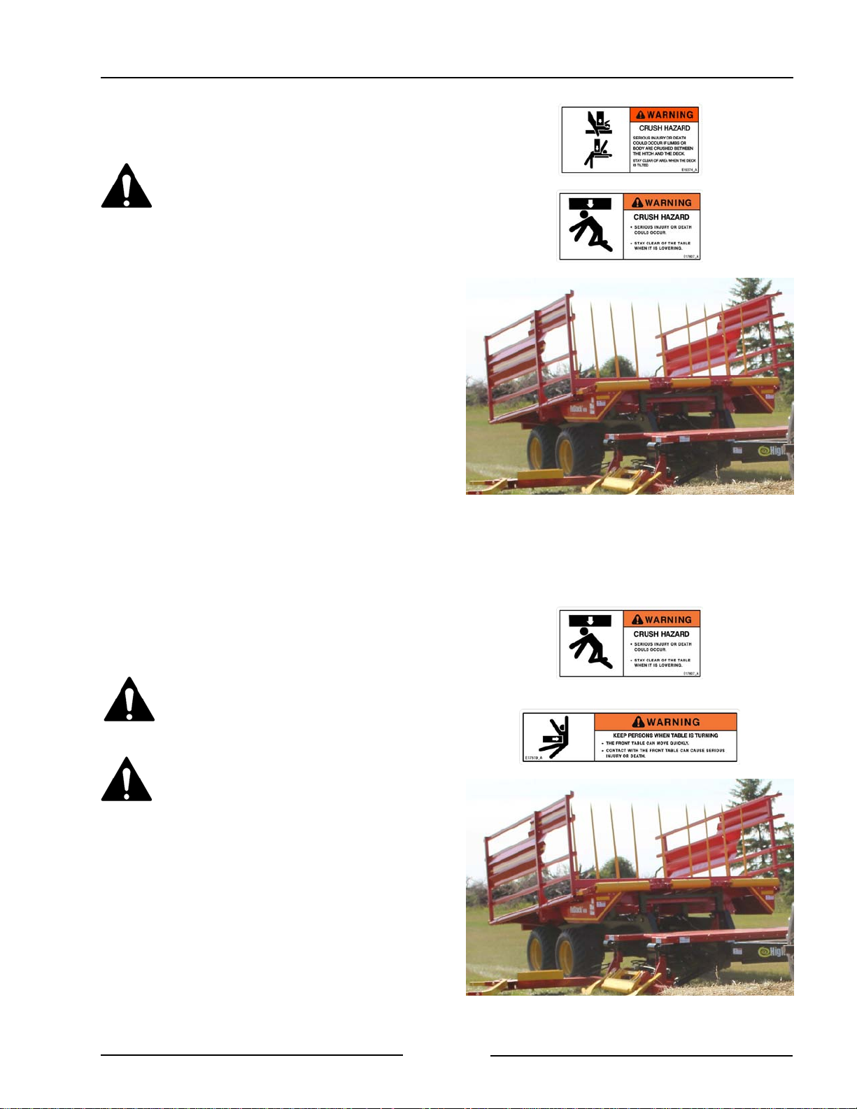
Section 7 - Storing the Bale Stacker
9. Lower the rear table to be resting on the
frame.
Stay clear of the table when
raising or lowering.
There is a crushing hazard if limbs
or body is placed between the
deck and ground or surrounding
objects when the deck is raised or
lowered.
10. Lower the front table to be resting on
the frame.
- Touch the Load button on the
display.
- Use the joystick button to lower the
front table.
Stay clear of the table when
raising or lowering.
Stay clear of the table when
turning.
- The table should be lowered
during long periods of storage so
the cylinders are in the retracted
position.
- The retracted position prevents
the rod from being exposed to
the weather.
Lower Rear Table onto the Frame
217146
Page 7-2
Lower Front Table onto the Frame
217146
Page 98
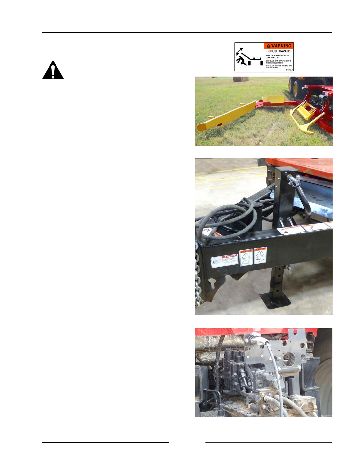
Section 7 - Storing the Bale Stacker
11. Lower the lift arm.
Stand clear of the bale lift arm.
The moving lift arm can cause
serious injury or death.
Never stand under lift arm when
lowering or raising.
Do not allow people near the lift
arm when being moved.
- The lift arm should be lowered during
long periods of storage so that the
cylinders are in the retracted position.
- The retracted position will prevent
the rod from being exposed to the
weather.
- Touch the Load button on the
display.
Lower Lift Arm, Open Clamp Arm
219038
- Use the joystick button to lower the
lift arm.
12. Open the clamp arm with the joystick
button so the cylinder is in the
retracted position to prevent the rod
being exposed to the weather.
13. Lower the hitch jack until the weight is
supported by the jack.
- Pull the pin to have the jack foot
drop.
- Ensure that the jack is resting on
solid level ground or resting on a
wood block.
- Crank the handle to raise the
clevis.
Lower the Hitch Jack to Support the Weight
219186
14. Relieve the pressure on the hydraulic
hoses and disconnect them.
15. Disconnect the electrical connections.
Page 7-3
Disconnect Hydraulics and Lighting Cable
217082
Page 99
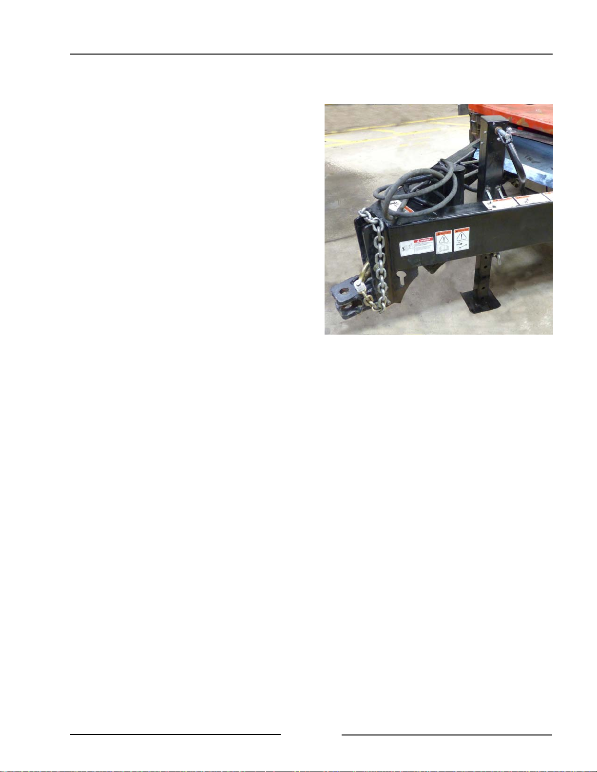
Section 7 - Storing the Bale Stacker
16. Disconnect the tractor cable from the
hitch harness.
17. Secure the hydraulic hoses and
electrical connector on the hitch to
keep them off the ground and clean.
18. Disconnect the hitch from the tractor.
19. Disconnect the safety chain.
Disconnect Hitch and Safety Chain
219032
Page 7-4
Page 100
Section 8 - Troubleshooting
8.0 TROUBLESHOOTING
Lift Arm
Symptom Problem Solution
Lift Arm Not Lifting Front table is up Lower the front table
Hydraulics not turned on Engage control valve in the
tractor
Hydraulic flow Lever in the tractor wrong
way for hydraulic flow
Hydraulics Check the hydraulic
connections to the hydraulic
block and the lift cylinder
Electrical Select "Load" on the display
Check the wiring to the
controller and to the
hydraulic block for power to
the solenoid
Check the fuses are
supplying power to the
control module and display
Rotation Sensor Check the condition of the
rotation sensor on the lift
arm. Check Section 2
"SENSOR STATUSES" and
also "ADJUST SETPOINTS"
for more information
Solenoid on Hydraulic Block Check for power to the
solenoid on the hydraulic
block while the button is
pressed
Page 8-1
 Loading...