

HighLine RCH Mower Operator's Manual

RCH™ Mower
Radial Contouring
Hitch Mower
Operator’s
Manual
E9145V1

RCH™ Mower
Radial Contouring
Hitch Mower
Operator’s
Manual
Printed in Canada Copyright © 2008 by Highline Manufacturing Ltd. All rights reserved.
The content of this manual was based on the most current information available as of the date of copyright. It is the policy of
Highline Manufacturing Limited to improve and develop our products continually. We reserve the right to make changes or add
improvements, at any time, without incurring any obligation to make changes or improvements on machines previously sold.
Highline Manufacturing Limited
HWY #27, P.O. Box 307
Vonda, SK S0K 4N0
Canada
Phone: 306.258.2233
Fax: 306.258.2010
Toll Free: 1.800.665.2010
E9145V1

Highline Manufacturing Ltd. RCH Mower
Highline Team Message
Congratulations on your purchase of the RCH Mower manufactured by Highline
Manufacturing Ltd. We are excited about your endeavor into cutting with the most technically
advanced rotary cutter known to date. You will find flexibility and maneuverability of operation
with this product that has never been experienced before. Welcome to the elite group of
Highline RCH mower owners.
This operator's manual has been prepared to provide information necessary for the safe and
efficient operation of your RCH Mower. In the manual you will find safety procedures,
maintenance routines and detailed operational instructions.
If you find that you require information not covered in this manual, please feel free to consult
your local dealer. Your dealer is always able to contact Highline for this technical information.
Highline Manufacturing Ltd. thanks and congratulates you for selecting a RCH Mower as your
machine of choice.
Highline Manufacturing Ltd.

Table of Contents
Section 1 - Safety
Serial Number
Safety Sign-off Form
Safety Alert Symbol
Section 2 - Transporting the Mower
Tractor Requirements
Ensure Correct PTO Speed
Adjust Single Point Drawbar Length
Connect Single Point Hitch
Connect the Safety Chain to Tractor
Connect the 2 Point Hitch
Tractor Wheel Tread Width Settings
Attach Driveline to PTO
Attach Hydraulics
Section 3 - Mower Preparation
Park On Level Ground
Ensure Safety Decals Are in Place
Ensure the SMV is Clean and Visible
Ensure Lighting is Working Properly
Check the Condition of the Blade Pans
Check the Condition of the Blades
Remove the Height Control Transport Lock
Remove the Wing Transport Lock Pins
Remove the Hitch Transport Lock Pin
Lower the Wings on Level Ground
General Safety
Safety Decals
Safety Decal Locations
Connect Lights
Place Hitch Jack in Storage Location
Check on the Condition of the Tires
Raise Wings and Lock in Place
Lower Mower Onto Height Control Lock
Install Hitch Transport Lock Pin
Verify SMV & Lights In Place and Working
Transport Speed
Level the Mower Center Section Deck
Determine the Primary Mowing Operating Conditions
Wing Adjustment Procedure
Set the Preferred Cutting Height
Inspect All the Hydraulic Cylinders
Check Condition of the Chain Guards
Inspect the Wheels and Tires
Inspect the Wing Skid Shoe
Ensure Driveline Clutches Will Slip
Ensure Driveline Shields Are in Place
Section 4 - Operating the Mower
Do Not Operate with the Wings Raised
Park on Level Ground
Remove the Wing Lock Pins
Remove the Hitch Lock Pin
Lower the Wings
Remove Debris from the Cutting Area
Rotate the Mower Deck to Move into the Cutting Area
Recommended Setup for a Quality Cut
Lower to the Cutting Height
Section 5 - Maintaining the Mower
Check Fluid Level in Gearboxes Daily
Lubrication
Gearbox Oil Changing Procedures
Run-In of the Friction Clutch
Section 6 - Storing the Mower
Clean Debris off the Mower Decks
Lubricate Grease Points
Tighten All Bolts to Torque
Touch-up the Paint to Prevent Rusting
Park the Mower on Level Ground
Lower the Mower
Support the Hitch with the Jack
Adjust Ground Speed
Operate the PTO at the Rated Speed
Allow the Wings to Float
Avoid Cutting into the Ditch
Rotate the Deck to Swing Away from Obstructions
Crossing Ditches and Steep Inclines
Wing Cutting Angles
Making Turns
Recommended Practices for A Quality Cut
Replacing the Clutch Friction Discs
Blade Replacement Procedure
Removing and Replacing the Blade Pan
Tires
Remove the Driveline from Tractor
Disconnect Safety Chain
Disconnect Hitch from Tractor
Relieve/Disconnect Hydraulic Hoses
Secure Hydraulic Hoses
Support Driveline in Holder
Change Oil in all Gearboxes
Section 7 - Troubleshooting
Operation
Wings
Wheels
Hitch
Section 8 - Mower Specifications
Options
Blades
Driveline Clutches
Drive Boxes
Drivelines

This Page Left Blank
Section 1 - Safety
SERIAL NUMBER
Your serial number is found on the serial number plate attached to the RCHTM Mower on the
left side of the fifth wheel hitch support tower.
It is important to record the serial number for proof of ownership and for any service or
maintenance assistance.
Serial Number
Owner
Model
Date of Purchase
Be Trained Before Operating Mowers!
Safety Training Makes a Difference.
The Association of Equipment Manufacturers offers the 22 minute video,
“Industrial and Agricultural Mower Safety Practices: A Safety Training
Program for Operators of Rotary-Type Mowing Equipment”.
This video reinforces the proper procedures to follow while operating rotary
mowing equipment.
To view the video on the Internet or to order a copy, please visit the Association of Equipment
Manufacturers website at www.aem.org and go the Safety & Training section.
The video does not replace the information contained in this Operator’s Manual. Please read and
understand this manual before operating the mower.
Page 1-1

Section 1 - Safety
SAFETY SIGN-OFF FORM
Highline Manufacturing Ltd. follows the general Safety Standards specified by the American
Society of Agricultural Engineers (ASAE) and the Occupational Safety and Health Administration
(OSHA). Anyone who will be operating and/or maintaining the Highline RCH Mower should read
and clearly understand all Safety, Operating and Maintenance information presented in this
manual.
Do not operate or allow someone to operate this equipment until this information has been
reviewed. This information should be reviewed by all operator’s before the season start-up.
This sign-off sheet is provided for record keeping to indicate that the person working with the
equipment has read and understood the information in the Operator’s Manual and has been
instructed in the safe operation of the equipment.
Date Employee’s Signature Employer’s Signature
Page 1-2
Section 1 - Safety
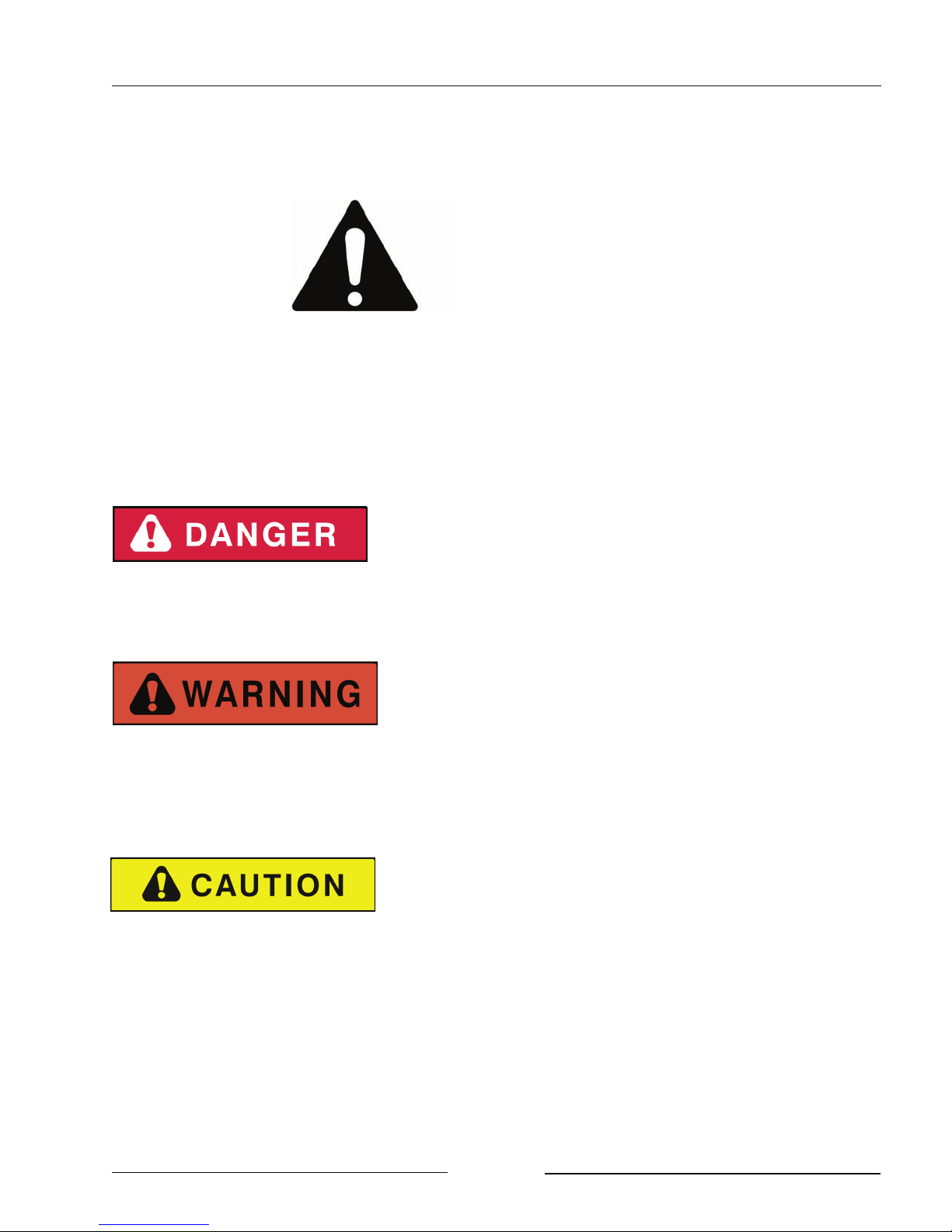
SAFETY ALERT SYMBOL
The Safety Alert Symbol means:
ATTENTION!
BECOME ALERT!
YOUR SAFETY IS INVOLVED!
The Safety Alert Symbol combined with a Signal Word alert to the presence of a hazard and the
degree of possible injury.
Indicates an imminently hazardous situation that, if not
avoided, WILL result in DEATH OR SERIOUS INJURY.
The color is Red with White lettering.
Indicates a potentially hazardous situation that, if not
avoided, COULD result in DEATH OR SERIOUS
INJURY, and includes hazards that are exposed when
guards are removed or unsafe practices. The color is
Orange with Black lettering.
Indicates a potentially hazardous situation that, if not
avoided, MAY result in MINOR INJURY. The color is
Yellow with Black lettering.
Page 1-3

Section 1 - Safety
GENERAL SAFETY
1. Ensure that anyone who is going to operate, maintain or work near the RCH Mower is
familiar with the recommended operating, maintenance procedures and safety information
contained in this manual and follows all the safety precautions.
2. “In addition to the design and configuration of the equipment, hazard control and accident
prevention are dependant upon the awareness, concern, prudence and proper training of
personnel involved in the operation, transport, maintenance and storage of the mower.” (Taken
from ASAE S474.1 Feb 04 - 5.2.5.1)
3. The mower shall not be operated without all the guards in place.
SAFETY DECALS
1. Keep decals and signs clean and legible at all times.
2. Replace decals and signs that are damaged, missing or have become illegible.
3. Replaced parts that displayed a decal should also display the current decal.
4. Decals are available from the Highline Parts Department.
5. Be familiar with the decals, the type of warning and the area or function(s) related to the
area(s) that requires your awareness.
Page 1-4
Section 1 - Safety
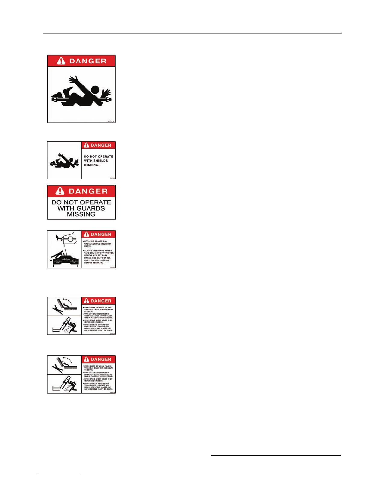
DO NOT CONTACT ROTATING DRIVELINE
Contact with rotating driveline will cause serious injury or death.
Keep all driveline guards in place.
Securely attach drivelines at both ends.
Check that the driveline guards turn freely on driveline.
DO NOT OPERATE WITH SHIELDS MISSING
DO NOT CONTACT ROTATING BLADES
Rotating blades can cause serious injury or death.
Always disengage power take off, shut off tractor, remove key, set
park brake and wait for all parts to stop turning before servicing.
Keep guards in place and in good condition.
DO NOT OPERATE MOWER WITH WINGS RAISED
Contact with exposed rotating blades may cause injury or death.
Rotating blades may throw objects, causing injury or death
STAND CLEAR OF WINGS
Falling wings can cause serious injury or death.
Wing cylinders must be fully retracted and wing lock pins in place
before servicing.
Never stand under wings when lowering or raising.
Page 1-5
Section 1 - Safety
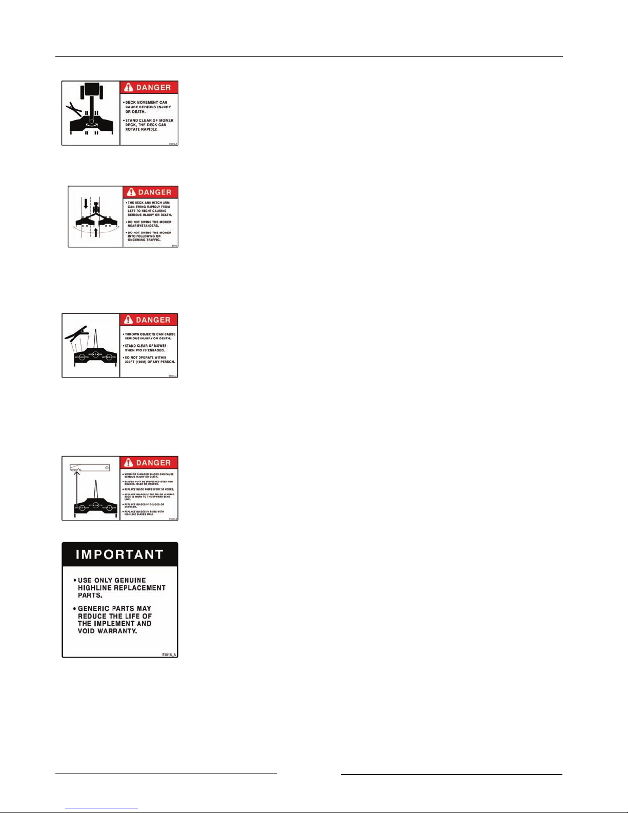
STAND CLEAR OF ROTATING DECK
Contact with rotating deck can cause serious injury or death.
Stand clear of mower deck. Mower deck can rotate rapidly.
DO NOT SWING DECK AND HITCH ARM NEAR BYSTANDERS
OR INTO TRAFFIC
The deck and hitch arm can swing rapidly from left to right causing
serious injury or death.
Do not swing the mower near bystanders.
Do not swing the mower into following or oncoming traffic.
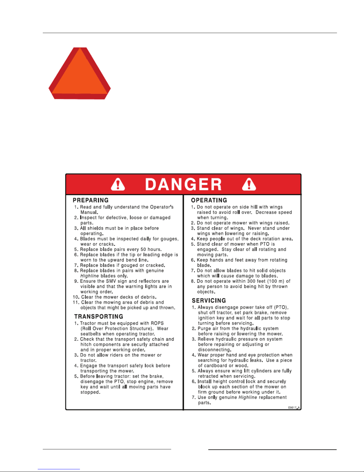
STAY BACK FROM MOWER IN OPERATION WHICH CAN
DISCHARGE OBJECTS SEVERAL HUNDREDS OF FEET
Thrown objects can cause serious injury or death.
Stand clear of mower when PTO is engaged.
Do not operate within 300 ft (100m) of any person.
Keep all shields and guards in place.
Clear mowing area of debris.
INSPECT BLADES FOR DAMAGE
Worn or damaged blades can cause serious injury or death.
Blades must be inspected daily for gouges, wear or cracks.
Replace blade pairs at maximum of 50 hours.
Replace blades if the tip or leading edge is worn to the upward bend
line. (The bend line is 2" (51mm) from the leading edge of a 4" (102
mm blade.)
Replace blades if gouged or cracked.
Blades must be changed in sets.
Use only Highline replacement parts.
Do not repair blades.
Page 1-6
Section 1 - Safety
ENSURE SLOW MOVING VEHICLE SIGN IS IN PLACE
Ensure the Slow Moving Vehicle sign is in place, clean and easily
visible.
Ensure the reflectors are in place, clean and easily visible.
READ AND FULLY UNDERSTAND THE INSTRUCTIONS ON THIS DECAL
Page 1-7
Section 1 - Safety
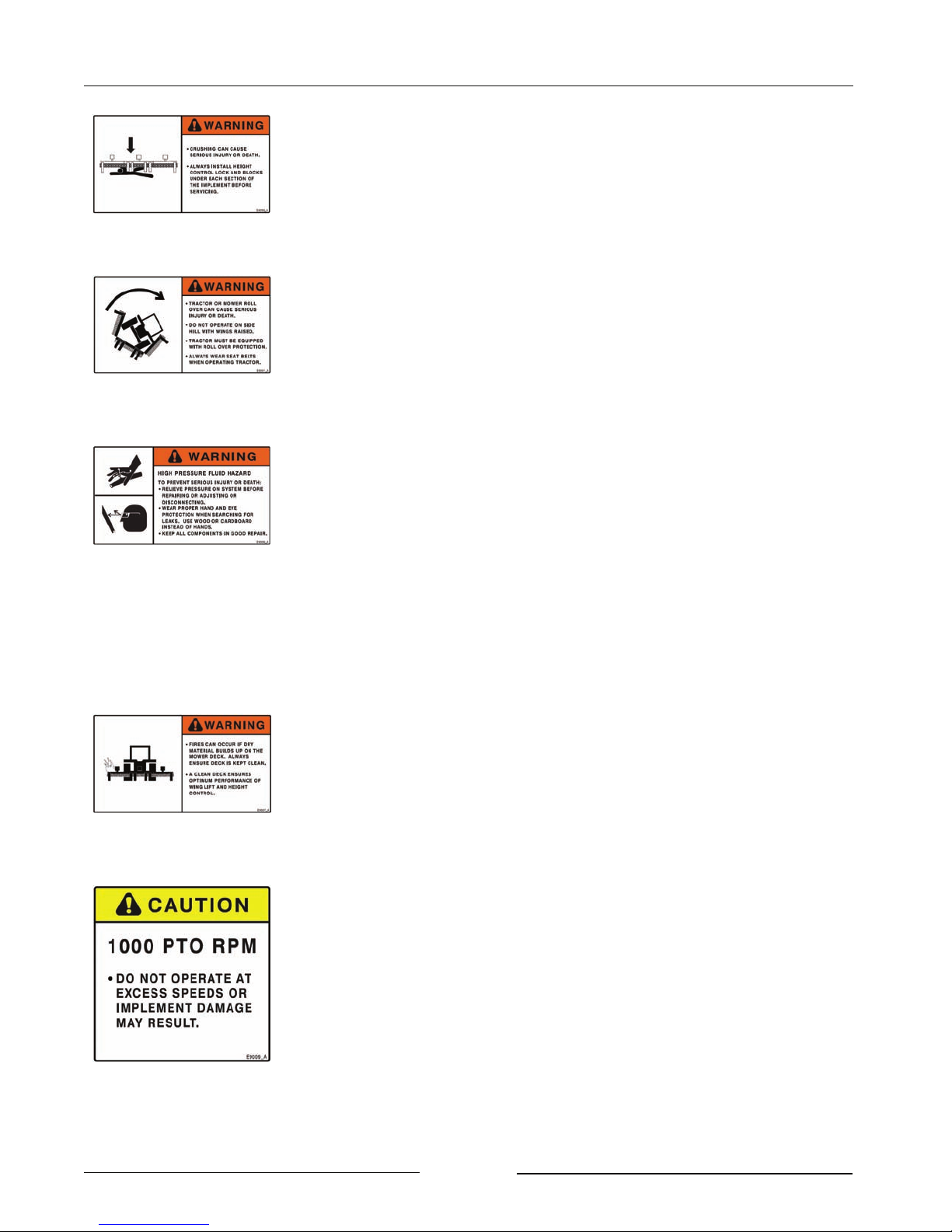
STAND CLEAR WHEN MOWER IS BEING RAISED OR
LOWERED
Crushing can cause serious injury or death.
Always install height control lock and blocks under each section of
the implement before servicing.
DO NOT OPERATE ON SIDE HILL WITH WINGS RAISED
Tractor or mower roll over can cause serious injury or death.
Tractor must be equipped with Roll Over Protection System.
(ROPS)
Always wear seat belts when operating tractor.
USE PAPER OR CARDBOARD TO CHECK FOR HYDRAULIC
LEAKS
To prevent serious injury or death:
Relieve pressure on hydraulic system before repairing, adjusting or
disconnecting.
Wear proper hand and eye protection when searching for leaks. Use
wood or cardboard instead of hands.
Keep all components in good repair.
KEEP MOWER DECK CLEAR OF DEBRIS
Fires can occur if dry material builds up on the mower deck.
Always ensure deck is kept clean.
A clean deck ensures optimum performance of wing lift and height
control.
DO NOT EXCEED PTO SPEED
Do not operate at excess speeds or damage to the mower may result.
Page 1-8
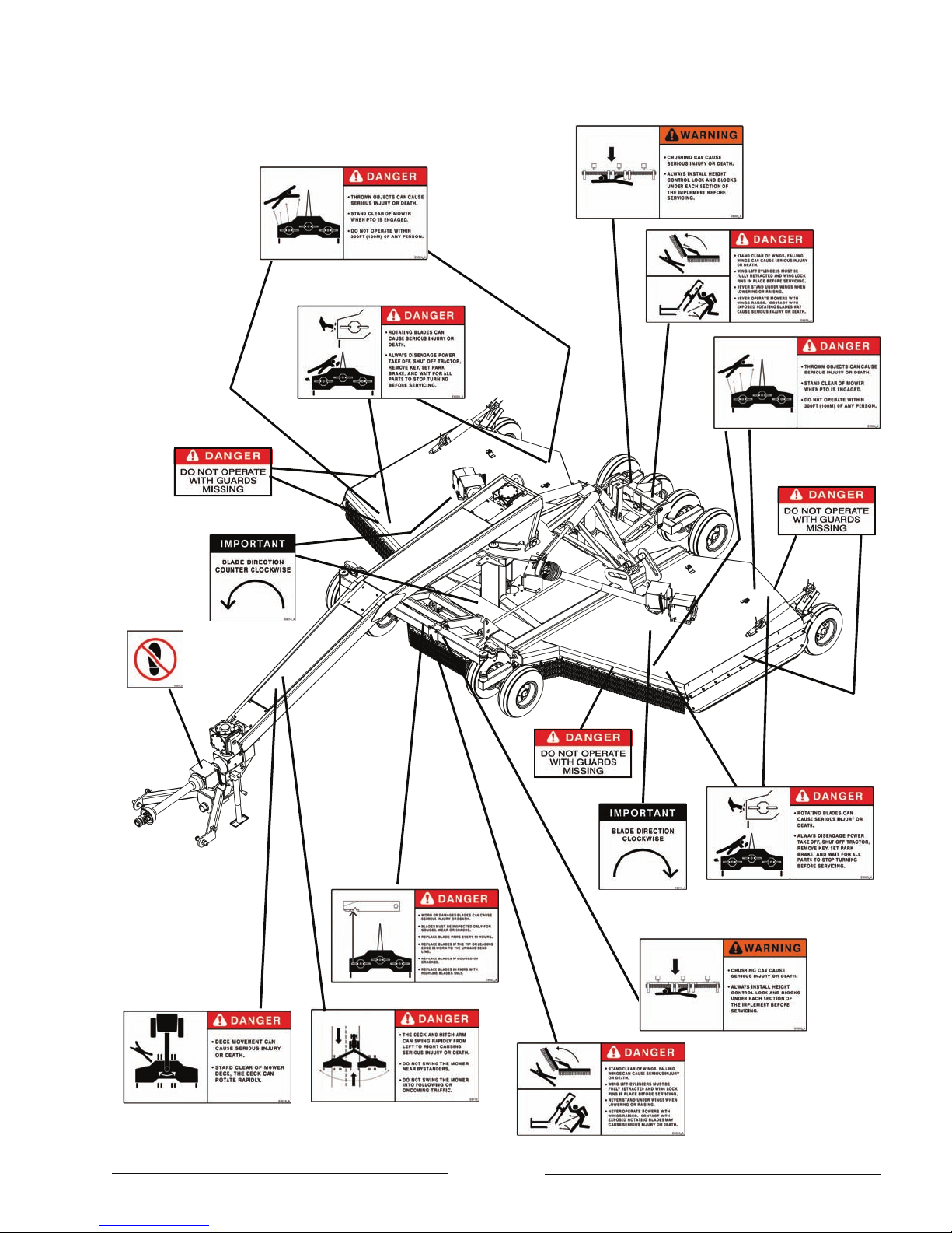
SAFETY DECAL LOCATIONS
Section 1 - Safety
Page 1-9
Section 1 - Safety
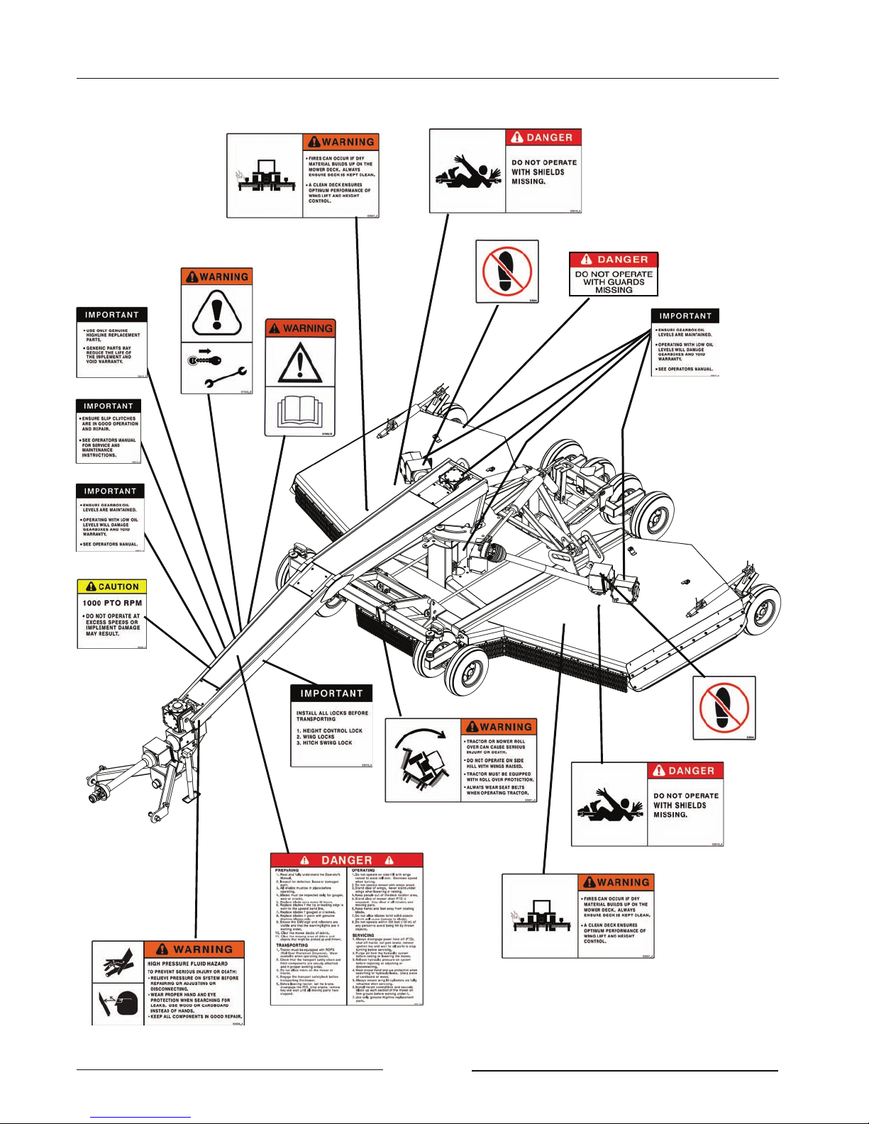
SAFETY DECAL LOCATIONS CONTINUED
Page 1-10
Section 2 - Transporting the Mower
2.0 TRANSPORTING THE MOWER
Only tow the mower behind a
properly sized and equipped
tractor which exceeds the weight
of the mower by 20%. Do not tow
the mower behind a truck or other
type of vehicle
Do not allow children or other
people to ride on the tractor or
mower. Falling off can result in
serious injury or death.
1. Tractor Requirements
- Minimum tractor weight of 9360 lbs
(4246 kg).
- Roll Over Protection System (ROPS)
- Working seatbelts
- 1 3/8" 21 spline PTO
- Minimum 80 PTO HP
Recommended is 100 PTO HP.
- 3 Spool Control Valves (SCV)
2. Ensure correct PTO speed
- Ensure that the tractor PTO speed
matches the mower’s gearbox speed
of 1000 rpm.
- Do not attempt to operate the mower
at a different PTO speed.
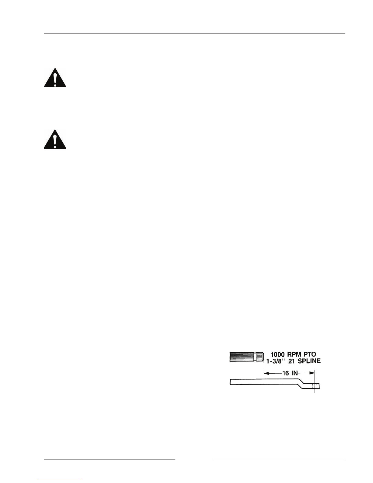
3. Adjust Single Point Hitch Drawbar Length
- Set the drawbar length to 16" (406
mm) for a 1 3/8" 21 spline PTO.
- This length is measured from the tip of
the PTO shaft end to the center of the
drawbar hole. (Refer to your tractor’s
operator manual for drawbar
adjustment procedures.)
Note: To prevent damage to the tractor
drawbar, avoid traveling at high
speeds and over rough terrain.
Note: Do not use PTO adapters. PTO
adapters will cause a driveline
failure and possible tractor
damage. Your mower warranty
will also be invalid.
Tractor Drawbar Adjustment for 1000 RPM
108005
Page 2-1
Section 2 - Transporting the Mower
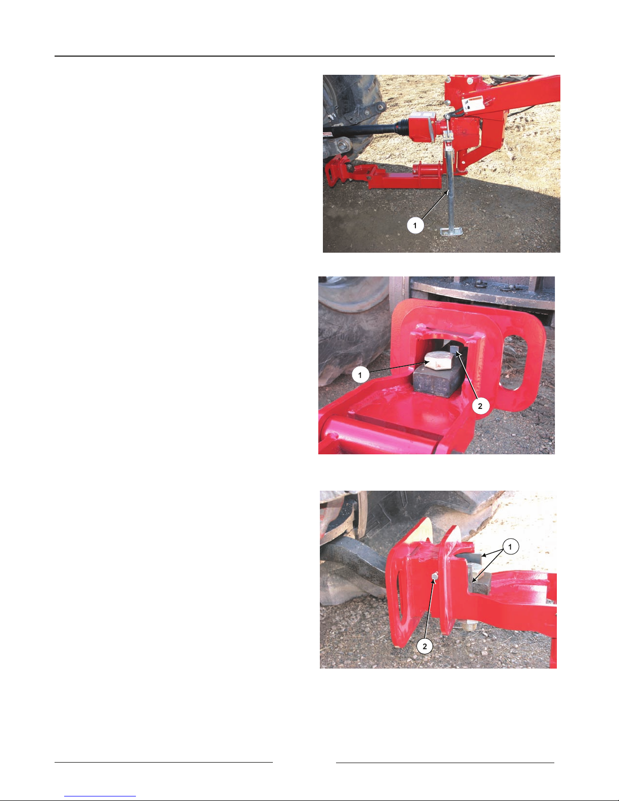
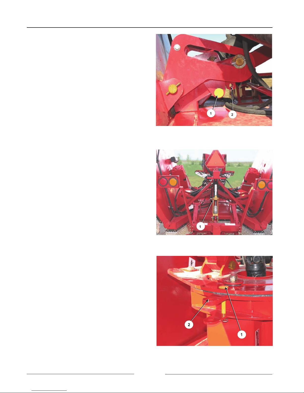
4. Connect Single Point Hitch (if applicable)
- Lift the Hitch Arm with the jack (1)
- The hitch arm is very heavy. Do
not attempt to lift it without using
the jack. - Adjust the hitch to
connect the drawbar.
- Connect the tractor drawbar to the
drawbar connector with:
- 1 1/4" x 5" bolt, washer and
locknut (1). Torque to 600 lbf (813
Nm)
- 3/4" x 3 ½" bolt, washer and
locknut (2). Torque to 260 lbf (352
Nm).
- Place a ½" thick shim plate (1) on
each side of the drawbar and fasten in
place with 3/8" x 5" bolt and locknut
(2 ).
Single Point Hitch on Jack
Connecting Drawbar Connector
107081C
107082C
Page 2-2
Drawbar Shims
107083C
Section 2 - Transporting the Mower
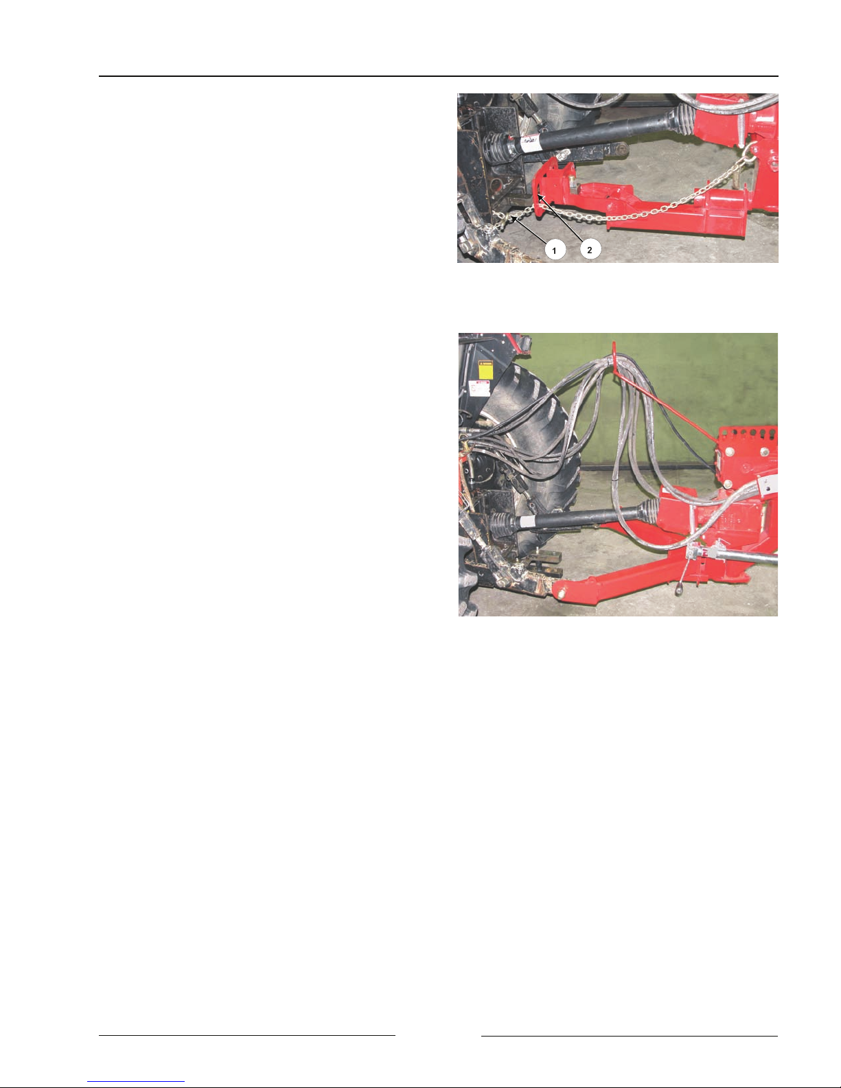
5. Connect the Safety Chain to the tractor.
- Ensure the safety chain rating is equal
or greater than the gross weight of the
mower.
- Route the safety chain (1) through the
large slot (2) in the drawbar connector.
Securely fasten the chain to the tractor
and lock in place with the hook lock.
6. Connect the 2 Point Hitch (if applicable)
- Adjust the lift links so that the PTO is
relatively level.
- Insert the 2 point hitch pins into the
hitch member and fasten in place with
D-ring pins.
Connect the Safety Chain
108006C
7. Tractor Wheel Tread Width Settings
- Increase the tractor rear wheel widths
to maintain tractor stability when
working on inclines or rough ground.
8. Route the hydraulic hoses and wiring
harness through the hose support arm.
2 Point Hitch Connection
108007
Page 2-3
Section 2 - Transporting the Mower
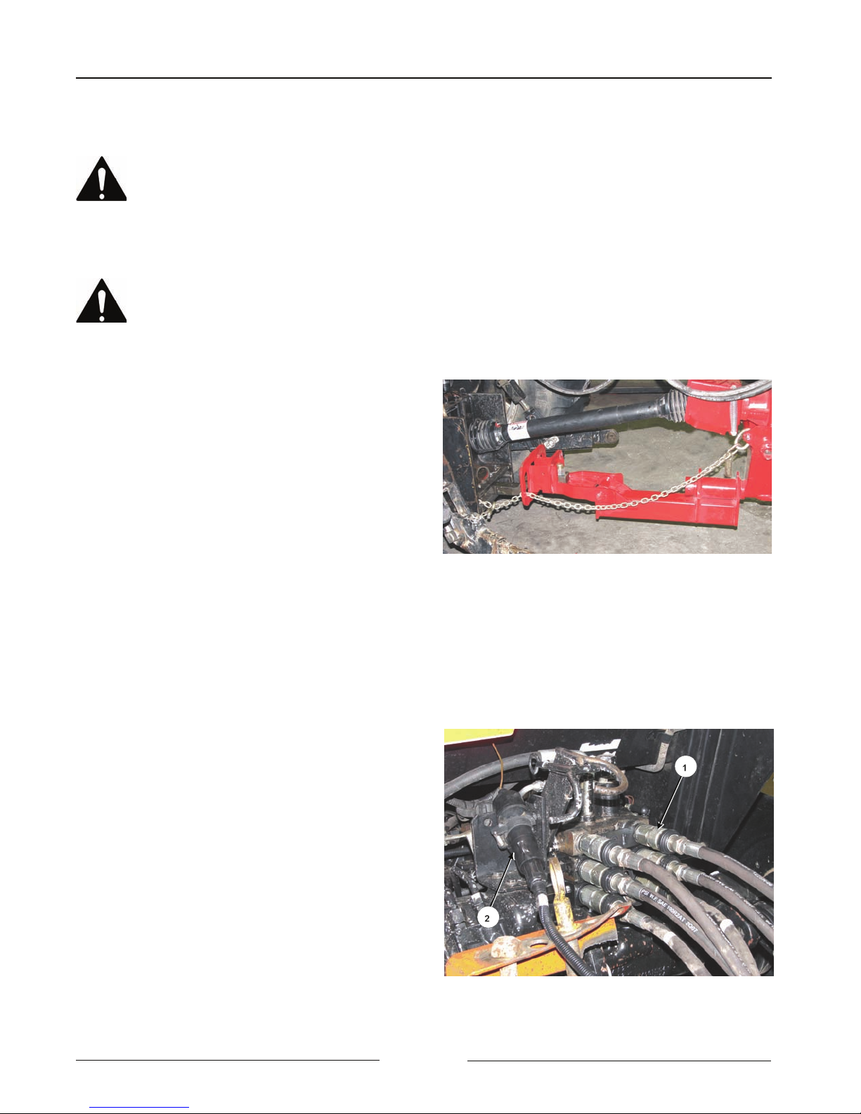
9. Attach Driveline to PTO
Shut off the tractor engine before
attaching PTO driveline.
Entanglement in the rotating
driveline can cause serious injury
or death.
The mower shall not be operated
without the driveline shields in
place.
1) Shut off the tractor engine and remove
the key.
2) Check that the driveline telescopes
easily and that the shields are in good
condition and rotate freely.
3) Lift the tractor PTO shield.
4) Support the driveline, pull back on the
yoke collar, align the splines by
rotating the mower driveline and push
the driveline into the tractor PTO shaft
until the collar snaps into place.
5) Push and pull the yoke several times
to ensure the driveline is locked. Do
not pull on the collar as this will
release the lock.
6) Lower the tractor & hitch PTO shields
into place.
Attach Driveline to PTO
108006
10. Attach Hydraulics
- The tractor must be equipped with 3
spool control valves (SCV) to control
the deck rotation, winging up and
down and height control.
- Clean the end of the hoses (1) and the
connection.
- Firmly push the hoses into the tractor
receptacle according to user
preference.
- Route the hoses so they do not
interfere with moving parts.
Page 2-4
Attach Hydraulics and Lighting
108008C
Section 2 - Transporting the Mower
11. Connect Lights
- Connect the light plug (2) into the
appropriate tractor receptacle.
- Ensure the light cable does not
interfere with or contact moving parts.
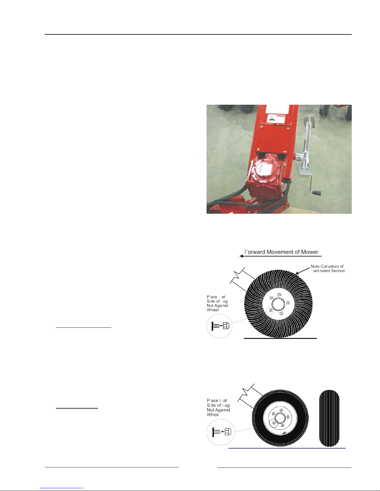
12. Place the Hitch Jack in the Storage
Location.
13. Check on the condition of all the tires.
- Verify that the lug nuts have the flat
side of the lug nut against the wheel
rim.
- Torque the lug nuts to 75 lbf (101
Nm).
Laminated Tires:
! Do not transport the mower on
roadways for long distances with
laminated tires.
Hitch Jack in Storage Location
Laminated Tires
107043
107074C
Aircraft Tires
! Air Filled Tire Pressure - Fill the tires
to 30 psi (207 Kpa).
Page 2-5
Aircraft Tires
107094C
Section 2 - Transporting the Mower
14. Raise the wings until they rest in
place.
- Install the Wing Lock Pins (1) from the
lock pin carrier (2) position. Clip the
pin into place.
15. Lower the mower until the hydraulic
height control cylinder is resting on the
height cylinder lock (1).
16. Install the Hitch Transport Lock Pin (1)
from the lock pin carrier (2) position.
Clip the pin into place.
Install the Wing Transport Lock Pins
Height Cylinder Resting on Lock
107085C
108077C
Page 2-6
Install the Hitch Transport Lock Pin
107086C

Section 2 - Transporting the Mower
17. Verify that the Slow Moving Vehicle
(SMV) sign (1) is clean and visible.
18. Verify that the taillights and flashing
warning lights (2) are clean, visible
and in good working order.
19. Transport Speed
Laminated Tires
- Do not exceed 15 mph (24 km/h).
Excessive speed can cause
damage to the machine and tire
sections.
Aircraft Tires (Air or Foam Filled)
- Do not exceed 20 mph (32 km/h).
Verify the SMV is Visible & Lights are Working
108077C2
Page 2-7

Section 2 - Transporting the Mower
This Page Left Blank
Page 2-8
Section 3 - Mower Preparation
3.0 MOWER PREPARATION
1. Park the tractor and mower on level
ground.
- Engage the tractor parking brake.
2. Ensure that all Decals are clean and in
place.
3. Ensure that the Slow Moving Vehicle
(SMV) sign is clean and visible.
4. Ensure the Lighting is working properly.
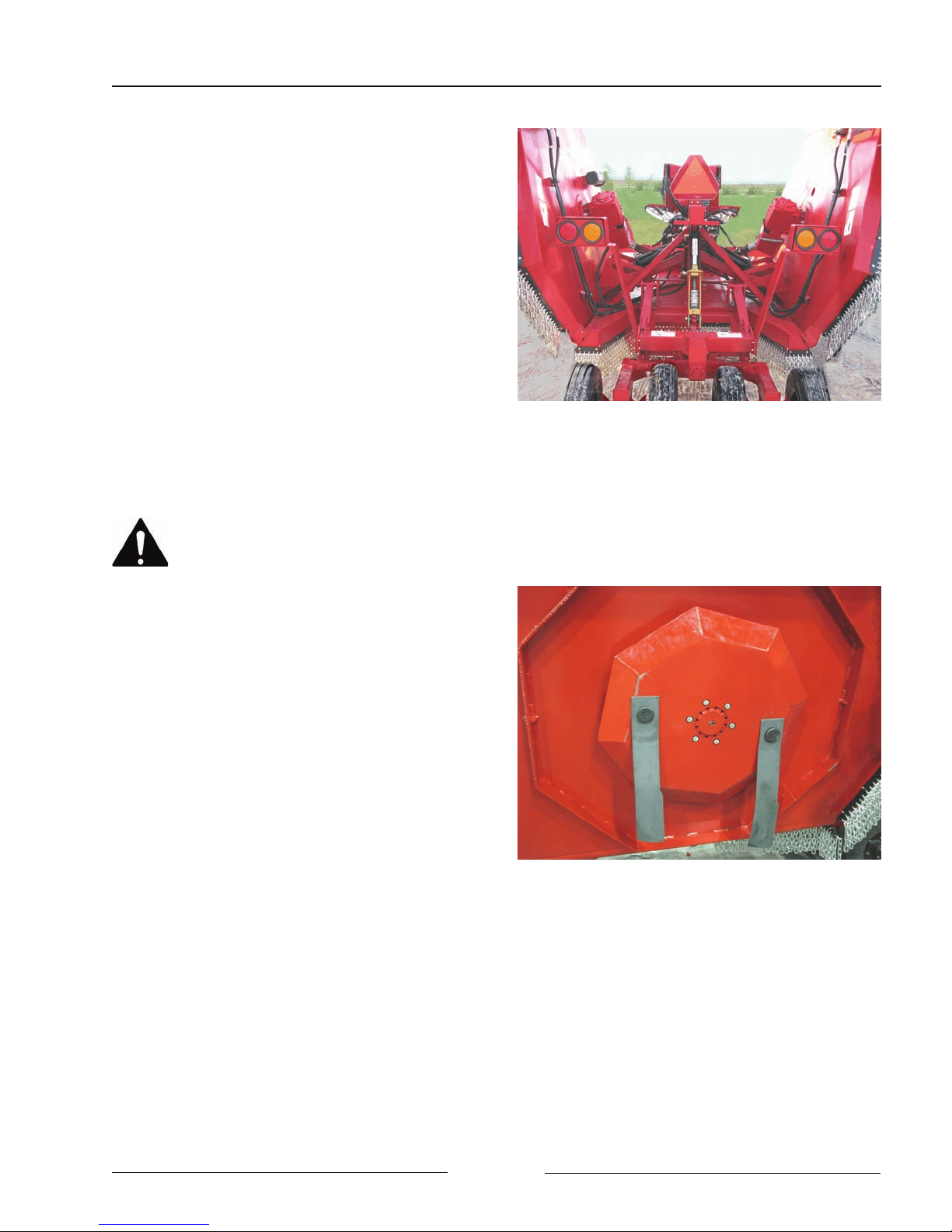
5. Check the Condition of the Blade Pans
Securely block-up the mower
before any work is done under the
mower when lifted up. This is to
prevent the mower from dropping
due to inadvertent operation of
controls, hydraulic leaking or
failure of any components.
- Clean debris and material buildup
from the blade pan area and from the
pans.
- Check that no wire or other materials
are wrapped around the driveshaft or
pan.
- Inspect the pan for damage caused by
contact with an immovable object.
Park On Level Ground
Inspect Blades & Hardware
108084
107034
- Inspect blade pan mounting hardware
for damage.
- Inspect blade mounting bolts for
damage.
Page 3-1
Section 3 - Mower Preparation
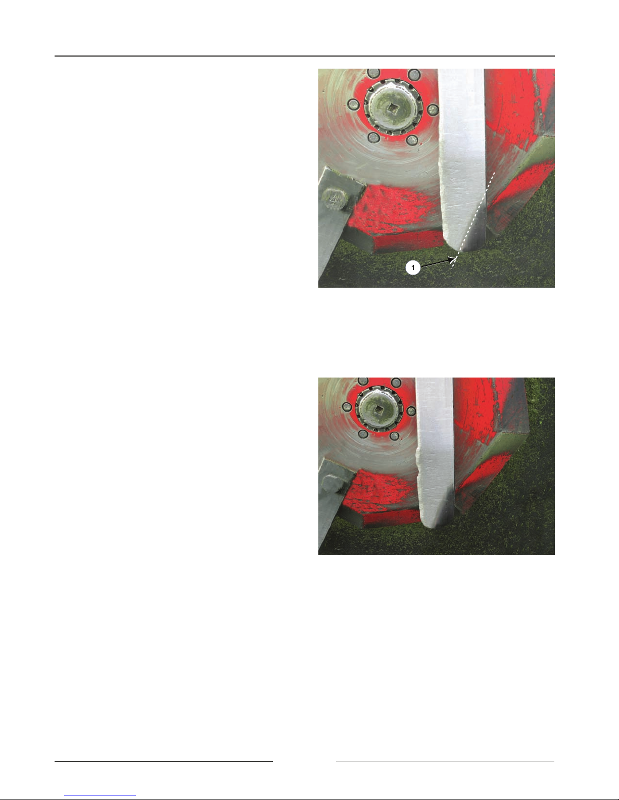
6. Check the Condition of the Blades
- Inspect the blades daily.
- Check that the blades swing freely.
Note: Do not sharpen the blades.
Replace them with Highline
blades.
! Replace the blade pair at a maximum
of 50 hours regardless of the wear
because of the possibility of metal
fatigue and non-visible cracks in the
blades. Replace with Highline blades.
! Replace the blade pair if the tip or
leading edge is worn to the upward
bend line (1). Replace with Highline
blades.
- The bend line is 2" (51mm)
from the leading edge of a 4"
(102mm) blade.
! Replace the blade pair if a blade is
gouged, has visible cracks or is bent.
Replace with Highline blades.
Replace blades in pairs with only
Highline blades.
-See “Blade Replacement
Procedure” in the Maintenance
Section.
Replace Blade When Tip Worn to Bend Line
Replace Blade When Gouged
1070802C
107080
Page 3-2
 Loading...