

Rotary Mower
™
RCH Hydro
™
Radial Contouring Hitch
O P E R A T O R ' S M A N U A L
E14362V1

Rotary Mower
RCH Hydro
™
Radial Contouring Hitch ™
Operator’s
Manual
Printed in Canada Copyright © 2016 by Highline Manufacturing Ltd. All rights reserved.
The content of this manual was based on the most current information available as of the date of copyright. It is the policy of
Highline Manufacturing Limited to improve and develop our products continually. We reserve the right to make changes or add
improvements, at any time, without incurring any obligation to make changes or improvements on machines previously sold.
Changes may not be reflected in this manual.
Highline Manufacturing Limited
HWY #27, P.O. Box 307
Vonda, SK S0K 4N0
Canada
Phone: 306.258.2233
Fax: 306.258.2010
Toll Free: 1.800.665.2010
E14362V1

Highline Manufacturing Ltd. Rotary Mower - RCH Hydro
Highline Team Message
Congratulations on your purchase of the Rotary Mower RCH Hydro manufactured by
Highline Manufacturing Ltd. We are excited about your endeavor into cutting with the most
technically advanced rotary cutter known to date. You will find flexibility and maneuverability
of operation with this product that has never been experienced before. Welcome to the elite
group of Highline Rotary Mower owners.
This Operator's Manual has been prepared to provide information necessary for the safe and
efficient operation of your Rotary Mower. In the manual you will find safety procedures,
maintenance routines and detailed operational instructions.
If you find that you require information not covered in this manual, please feel free to consult
your local dealer. Your dealer is always able to contact Highline for this technical information.
Highline Manufacturing Ltd. thanks and congratulates you for selecting a Rotary Mower as your
machine of choice.
Highline Manufacturing Ltd.

Table of Contents
Section 1 - Safety
Serial Number . . . . . . . . . . . . . . . . . . . . . . . . . . . . . . . . . . . . . . . . . . . . . . . . . . . . . . . . . . . . . . . . . . . . . . . . . . . . . . . . . . 1
Safety Sign-off Form . . . . . . . . . . . . . . . . . . . . . . . . . . . . . . . . . . . . . . . . . . . . . . . . . . . . . . . . . . . . . . . . . . . . . . . . . . . . . 2
Safety Alert Symbol . . . . . . . . . . . . . . . . . . . . . . . . . . . . . . . . . . . . . . . . . . . . . . . . . . . . . . . . . . . . . . . . . . . . . . . . . . . . . . 3
General Safety . . . . . . . . . . . . . . . . . . . . . . . . . . . . . . . . . . . . . . . . . . . . . . . . . . . . . . . . . . . . . . . . . . . . . . . . . . . . . . . . . 4
Safety Decals . . . . . . . . . . . . . . . . . . . . . . . . . . . . . . . . . . . . . . . . . . . . . . . . . . . . . . . . . . . . . . . . . . . . . . . . . . . . . . . . . . 4
Safety Decal Locations . . . . . . . . . . . . . . . . . . . . . . . . . . . . . . . . . . . . . . . . . . . . . . . . . . . . . . . . . . . . . . . . . . . . . . . . . . 10
Section 2 - Transporting the Mower
Tractor requirements . . . . . . . . . . . . . . . . . . . . . . . . . . . . . . . . . . . . . . . . . . . . . . . . . . . . . . . . . . . . . . . . . . . . . . . . . . . . . 1
Ensure correct PTO speed . . . . . . . . . . . . . . . . . . . . . . . . . . . . . . . . . . . . . . . . . . . . . . . . . . . . . . . . . . . . . . . . . . . . . . . . 1
Adjust tractor drawbar length . . . . . . . . . . . . . . . . . . . . . . . . . . . . . . . . . . . . . . . . . . . . . . . . . . . . . . . . . . . . . . . . . . . . . . 1
Lift the hitch . . . . . . . . . . . . . . . . . . . . . . . . . . . . . . . . . . . . . . . . . . . . . . . . . . . . . . . . . . . . . . . . . . . . . . . . . . . . . . . . . . . . 2
Connect the hitch . . . . . . . . . . . . . . . . . . . . . . . . . . . . . . . . . . . . . . . . . . . . . . . . . . . . . . . . . . . . . . . . . . . . . . . . . . . . . . . 2
Connect the safety chain to the tractor. . . . . . . . . . . . . . . . . . . . . . . . . . . . . . . . . . . . . . . . . . . . . . . . . . . . . . . . . . . . . . . . 3
Tractor wheel tread width settings . . . . . . . . . . . . . . . . . . . . . . . . . . . . . . . . . . . . . . . . . . . . . . . . . . . . . . . . . . . . . . . . . . . 3
Route the hydraulic hoses and wiring harness . . . . . . . . . . . . . . . . . . . . . . . . . . . . . . . . . . . . . . . . . . . . . . . . . . . . . . . . . 3
Attach the driveline to the PTO . . . . . . . . . . . . . . . . . . . . . . . . . . . . . . . . . . . . . . . . . . . . . . . . . . . . . . . . . . . . . . . . . . . . . 4
Attach the hydraulics . . . . . . . . . . . . . . . . . . . . . . . . . . . . . . . . . . . . . . . . . . . . . . . . . . . . . . . . . . . . . . . . . . . . . . . . . . . . . 5
Connect the lights . . . . . . . . . . . . . . . . . . . . . . . . . . . . . . . . . . . . . . . . . . . . . . . . . . . . . . . . . . . . . . . . . . . . . . . . . . . . . . . 5
Place the hitch jack in the storage location. . . . . . . . . . . . . . . . . . . . . . . . . . . . . . . . . . . . . . . . . . . . . . . . . . . . . . . . . . . . 5
Check on the condition of all the tires. . . . . . . . . . . . . . . . . . . . . . . . . . . . . . . . . . . . . . . . . . . . . . . . . . . . . . . . . . . . . . . . 6
Raise the wings until they rest in place. . . . . . . . . . . . . . . . . . . . . . . . . . . . . . . . . . . . . . . . . . . . . . . . . . . . . . . . . . . . . . . 6
Install the wing transport lock pins . . . . . . . . . . . . . . . . . . . . . . . . . . . . . . . . . . . . . . . . . . . . . . . . . . . . . . . . . . . . . . . . . . 6
Lower the mower . . . . . . . . . . . . . . . . . . . . . . . . . . . . . . . . . . . . . . . . . . . . . . . . . . . . . . . . . . . . . . . . . . . . . . . . . . . . . . . 6
Height cylinder transport lock . . . . . . . . . . . . . . . . . . . . . . . . . . . . . . . . . . . . . . . . . . . . . . . . . . . . . . . . . . . . . . . . . . . . . . 6
Install the hitch transport locks . . . . . . . . . . . . . . . . . . . . . . . . . . . . . . . . . . . . . . . . . . . . . . . . . . . . . . . . . . . . . . . . . . . . . 7
Slow Moving Vehicle (SMV) sign . . . . . . . . . . . . . . . . . . . . . . . . . . . . . . . . . . . . . . . . . . . . . . . . . . . . . . . . . . . . . . . . . . . 7
taillights and flashing warning lights . . . . . . . . . . . . . . . . . . . . . . . . . . . . . . . . . . . . . . . . . . . . . . . . . . . . . . . . . . . . . . . . . 7
Transport speed . . . . . . . . . . . . . . . . . . . . . . . . . . . . . . . . . . . . . . . . . . . . . . . . . . . . . . . . . . . . . . . . . . . . . . . . . . . . . . . . 7
Section 3 - Mower Preparation
Park the tractor and mower on level ground. . . . . . . . . . . . . . . . . . . . . . . . . . . . . . . . . . . . . . . . . . . . . . . . . . . . . . . . . . . . 1
Ensure the lighting is working properly . . . . . . . . . . . . . . . . . . . . . . . . . . . . . . . . . . . . . . . . . . . . . . . . . . . . . . . . . . . . . . . 1
Optional joystick control, confirm that the hydraulic control block is configured . . . . . . . . . . . . . . . . . . . . . . . . . . . . . . . . 1
Check the condition of the blade pans . . . . . . . . . . . . . . . . . . . . . . . . . . . . . . . . . . . . . . . . . . . . . . . . . . . . . . . . . . . . . . . 2
Check the condition of the blades . . . . . . . . . . . . . . . . . . . . . . . . . . . . . . . . . . . . . . . . . . . . . . . . . . . . . . . . . . . . . . . . . . . 3
Lift the height control transport lock . . . . . . . . . . . . . . . . . . . . . . . . . . . . . . . . . . . . . . . . . . . . . . . . . . . . . . . . . . . . . . . . . 4
Remove the wing transport lock pins . . . . . . . . . . . . . . . . . . . . . . . . . . . . . . . . . . . . . . . . . . . . . . . . . . . . . . . . . . . . . . . . 4
Remove the hitch transport locks . . . . . . . . . . . . . . . . . . . . . . . . . . . . . . . . . . . . . . . . . . . . . . . . . . . . . . . . . . . . . . . . . . . 4
Level the mower center section deck front to back . . . . . . . . . . . . . . . . . . . . . . . . . . . . . . . . . . . . . . . . . . . . . . . . . . . . . 5
Verify the blade direction rotation . . . . . . . . . . . . . . . . . . . . . . . . . . . . . . . . . . . . . . . . . . . . . . . . . . . . . . . . . . . . . . . . . . . 7
Determine the wing height adjustment . . . . . . . . . . . . . . . . . . . . . . . . . . . . . . . . . . . . . . . . . . . . . . . . . . . . . . . . . . . . . . . 8
Wing height adjustment procedure . . . . . . . . . . . . . . . . . . . . . . . . . . . . . . . . . . . . . . . . . . . . . . . . . . . . . . . . . . . . . . . . . 10
Set the preferred cutting height . . . . . . . . . . . . . . . . . . . . . . . . . . . . . . . . . . . . . . . . . . . . . . . . . . . . . . . . . . . . . . . . . . . . 11
Inspect all the hydraulic cylinders, pump, motors and hoses . . . . . . . . . . . . . . . . . . . . . . . . . . . . . . . . . . . . . . . . . . . . . 11
Clear debris from the oil cooling tank, radiator and cooling fan . . . . . . . . . . . . . . . . . . . . . . . . . . . . . . . . . . . . . . . . . . . 12
Check the oil level in the oil tank . . . . . . . . . . . . . . . . . . . . . . . . . . . . . . . . . . . . . . . . . . . . . . . . . . . . . . . . . . . . . . . . . . . 13
Ensure the shutoff valves at the bottom of the tank are in the open position . . . . . . . . . . . . . . . . . . . . . . . . . . . . . . . . . 14
Check the oil filter operating pressure . . . . . . . . . . . . . . . . . . . . . . . . . . . . . . . . . . . . . . . . . . . . . . . . . . . . . . . . . . . . . . . 14
Check the oil level in the pump gearbox . . . . . . . . . . . . . . . . . . . . . . . . . . . . . . . . . . . . . . . . . . . . . . . . . . . . . . . . . . . . . 15
Check the condition of the chain guards . . . . . . . . . . . . . . . . . . . . . . . . . . . . . . . . . . . . . . . . . . . . . . . . . . . . . . . . . . . . 16
Inspect the wheels and tires . . . . . . . . . . . . . . . . . . . . . . . . . . . . . . . . . . . . . . . . . . . . . . . . . . . . . . . . . . . . . . . . . . . . . . 16
Inspect the wing skid plate . . . . . . . . . . . . . . . . . . . . . . . . . . . . . . . . . . . . . . . . . . . . . . . . . . . . . . . . . . . . . . . . . . . . . . . 16
Inspect the center section skid plate . . . . . . . . . . . . . . . . . . . . . . . . . . . . . . . . . . . . . . . . . . . . . . . . . . . . . . . . . . . . . . . 16
wing skid plate wheel is installed, check the condition . . . . . . . . . . . . . . . . . . . . . . . . . . . . . . . . . . . . . . . . . . . . . . . . . . 17
10 Foot Models, inspect the center deck skid and counterweights . . . . . . . . . . . . . . . . . . . . . . . . . . . . . . . . . . . . . . . . 17
Ensure the driveline is securely attached . . . . . . . . . . . . . . . . . . . . . . . . . . . . . . . . . . . . . . . . . . . . . . . . . . . . . . . . . . . . 18
Ensure the driveline shields are lowered into place . . . . . . . . . . . . . . . . . . . . . . . . . . . . . . . . . . . . . . . . . . . . . . . . . . . . 18
Lubricate all grease fittings and check the fluid level . . . . . . . . . . . . . . . . . . . . . . . . . . . . . . . . . . . . . . . . . . . . . . . . . . . 18

Section 4 - Operating the Mower
Hydraulic Oil Temperature . . . . . . . . . . . . . . . . . . . . . . . . . . . . . . . . . . . . . . . . . . . . . . . . . . . . . . . . . . . . . . . . 1
Move both wing transport lock pins . . . . . . . . . . . . . . . . . . . . . . . . . . . . . . . . . . . . . . . . . . . . . . . . . . . . . . . . . 2
Remove the hitch cylinder transport locks . . . . . . . . . . . . . . . . . . . . . . . . . . . . . . . . . . . . . . . . . . . . . . . . . . . . 3
Lower the wings . . . . . . . . . . . . . . . . . . . . . . . . . . . . . . . . . . . . . . . . . . . . . . . . . . . . . . . . . . . . . . . . . . . . . . . . 3
Controlling the Mower . . . . . . . . . . . . . . . . . . . . . . . . . . . . . . . . . . . . . . . . . . . . . . . . . . . . . . . . . . . . . . . . . . . . 4
Control Box - 3 Remote Tractor . . . . . . . . . . . . . . . . . . . . . . . . . . . . . . . . . . . . . . . . . . . . . . . . . . . . . . . . . . . . 4
Control Box - Joystick Control (1 Remote) . . . . . . . . . . . . . . . . . . . . . . . . . . . . . . . . . . . . . . . . . . . . . . . . . . . . 6
Joystick Control . . . . . . . . . . . . . . . . . . . . . . . . . . . . . . . . . . . . . . . . . . . . . . . . . . . . . . . . . . . . . . . . . . . . . . . . 7
Swing the mower deck . . . . . . . . . . . . . . . . . . . . . . . . . . . . . . . . . . . . . . . . . . . . . . . . . . . . . . . . . . . . . . . . . . 8
Lower to the cutting height . . . . . . . . . . . . . . . . . . . . . . . . . . . . . . . . . . . . . . . . . . . . . . . . . . . . . . . . . . . . . . . 10
Adjust ground speed . . . . . . . . . . . . . . . . . . . . . . . . . . . . . . . . . . . . . . . . . . . . . . . . . . . . . . . . . . . . . . . . . . . 10
Move the wing blade pans switches on the control box . . . . . . . . . . . . . . . . . . . . . . . . . . . . . . . . . . . . . . . . 11
Operate the PTO . . . . . . . . . . . . . . . . . . . . . . . . . . . . . . . . . . . . . . . . . . . . . . . . . . . . . . . . . . . . . . . . . . . . . . 11
Allow the wings to float . . . . . . . . . . . . . . . . . . . . . . . . . . . . . . . . . . . . . . . . . . . . . . . . . . . . . . . . . . . . . . . . . . 11
Avoid cutting into the ditch. . . . . . . . . . . . . . . . . . . . . . . . . . . . . . . . . . . . . . . . . . . . . . . . . . . . . . . . . . . . . . . . 11
Swing the mower deck away from obstructions . . . . . . . . . . . . . . . . . . . . . . . . . . . . . . . . . . . . . . . . . . . . . . . 12
Check that the hydraulic oil cooling fan is operating . . . . . . . . . . . . . . . . . . . . . . . . . . . . . . . . . . . . . . . . . . . 12
Responding to a High Oil Temperature Warning . . . . . . . . . . . . . . . . . . . . . . . . . . . . . . . . . . . . . . . . . . . . . . 13
Do not drive or swing the mower into following or on-coming traffic . . . . . . . . . . . . . . . . . . . . . . . . . . . . . . . 14
Cross ditches and steep inclines . . . . . . . . . . . . . . . . . . . . . . . . . . . . . . . . . . . . . . . . . . . . . . . . . . . . . . . . . . 14
Making Turns . . . . . . . . . . . . . . . . . . . . . . . . . . . . . . . . . . . . . . . . . . . . . . . . . . . . . . . . . . . . . . . . . . . . . . . . . 15
Recommended Practices for a Quality Cut . . . . . . . . . . . . . . . . . . . . . . . . . . . . . . . . . . . . . . . . . . . . . . . . . . 16
Section 5 - Maintaining the Mower
Check the oil level in the pump gearbox. . . . . . . . . . . . . . . . . . . . . . . . . . . . . . . . . . . . . . . . . . . . . . . . . . . . . . . . . . . . . . 1
Check the oil level in the oil tank . . . . . . . . . . . . . . . . . . . . . . . . . . . . . . . . . . . . . . . . . . . . . . . . . . . . . . . . . . . . . . . . . . . 2
Check the oil filter operating pressure . . . . . . . . . . . . . . . . . . . . . . . . . . . . . . . . . . . . . . . . . . . . . . . . . . . . . . . . . . . . . . . 3
Replacing the Filter . . . . . . . . . . . . . . . . . . . . . . . . . . . . . . . . . . . . . . . . . . . . . . . . . . . . . . . . . . . . . . . . . . . . . . . . . . . . . . 3
Clear debris from the oil cooling tank, radiator and cooling fan . . . . . . . . . . . . . . . . . . . . . . . . . . . . . . . . . . . . . . . . . . . 4
Lubrication . . . . . . . . . . . . . . . . . . . . . . . . . . . . . . . . . . . . . . . . . . . . . . . . . . . . . . . . . . . . . . . . . . . . . . . . . . . . . . . . . . . . 5
Oil Tank Oil Changing Procedures . . . . . . . . . . . . . . . . . . . . . . . . . . . . . . . . . . . . . . . . . . . . . . . . . . . . . . . . . . . . . . . . . . 8
Gearbox Oil Changing Procedures . . . . . . . . . . . . . . . . . . . . . . . . . . . . . . . . . . . . . . . . . . . . . . . . . . . . . . . . . . . . . . . . . . 9
Blade Replacement Procedure . . . . . . . . . . . . . . . . . . . . . . . . . . . . . . . . . . . . . . . . . . . . . . . . . . . . . . . . . . . . . . . . . . . . 10
Removing and Replacing the Blade Pan . . . . . . . . . . . . . . . . . . . . . . . . . . . . . . . . . . . . . . . . . . . . . . . . . . . . . . . . . . . . 12
Front Tires . . . . . . . . . . . . . . . . . . . . . . . . . . . . . . . . . . . . . . . . . . . . . . . . . . . . . . . . . . . . . . . . . . . . . . . . . . . . . . . . . . . 17
Rear Tires . . . . . . . . . . . . . . . . . . . . . . . . . . . . . . . . . . . . . . . . . . . . . . . . . . . . . . . . . . . . . . . . . . . . . . . . . . . . . . . . . . . . 18
Section 6 - Storing the Mower
Clean all the debris off the mower decks . . . . . . . . . . . . . . . . . . . . . . . . . . . . . . . . . . . . . . . . . . . . . . . . . . . . . . . . . . . . . 1
Lubricate all mower grease points . . . . . . . . . . . . . . . . . . . . . . . . . . . . . . . . . . . . . . . . . . . . . . . . . . . . . . . . . . . . . . . . . . 1
Park the mower on level ground . . . . . . . . . . . . . . . . . . . . . . . . . . . . . . . . . . . . . . . . . . . . . . . . . . . . . . . . . . . . . . . . . . . . 1
Lower the mower until the hydraulic height control cylinder is resting on the transport lock . . . . . . . . . . . . . . . . . . . . . . 1
Place the wing transport lock pins in place . . . . . . . . . . . . . . . . . . . . . . . . . . . . . . . . . . . . . . . . . . . . . . . . . . . . . . . . . . . 2
jack from the storage position and place it onto the hitch . . . . . . . . . . . . . . . . . . . . . . . . . . . . . . . . . . . . . . . . . . . . . . . . 2
Remove the driveline . . . . . . . . . . . . . . . . . . . . . . . . . . . . . . . . . . . . . . . . . . . . . . . . . . . . . . . . . . . . . . . . . . . . . . . . . . . . 3
Disconnect the safety chain . . . . . . . . . . . . . . . . . . . . . . . . . . . . . . . . . . . . . . . . . . . . . . . . . . . . . . . . . . . . . . . . . . . . . . . 3
Disconnect the hitch . . . . . . . . . . . . . . . . . . . . . . . . . . . . . . . . . . . . . . . . . . . . . . . . . . . . . . . . . . . . . . . . . . . . . . . . . . . . 3
hydraulic hoses and disconnect them. . . . . . . . . . . . . . . . . . . . . . . . . . . . . . . . . . . . . . . . . . . . . . . . . . . . . . . . . . . . . . . . 3
Disconnect the electrical connection . . . . . . . . . . . . . . . . . . . . . . . . . . . . . . . . . . . . . . . . . . . . . . . . . . . . . . . . . . . . . . . . 3
Secure the hydraulic hoses . . . . . . . . . . . . . . . . . . . . . . . . . . . . . . . . . . . . . . . . . . . . . . . . . . . . . . . . . . . . . . . . . . . . . . . 4
Place the PTO driveline in the support bracket . . . . . . . . . . . . . . . . . . . . . . . . . . . . . . . . . . . . . . . . . . . . . . . . . . . . . . . . 4
Change the oil in the gear box . . . . . . . . . . . . . . . . . . . . . . . . . . . . . . . . . . . . . . . . . . . . . . . . . . . . . . . . . . . . . . . . . . . . . 4

Section 7 - Troubleshooting
Operation .. . . . . . . . . . . . . . . . . . . . . . . . . . . . . . . . . . . . . . . . . . . . . . . . . . . . . . . . . . . . . . . . . . . . . . . . . . . . 1
Center Section . . . . . . . . . . . . . . . . . . . . . . . . . . . . . . . . . . . . . . . . . . . . . . . . . . . . . . . . . . . . . . . . . . . . . . . . . 3
Wings . . . . . . . . . . . . . . . . . . . . . . . . . . . . . . . . . . . . . . . . . . . . . . . . . . . . . . . . . . . . . . . . . . . . . . . . . . . . . . . . 5
Wheels . . . . . . . . . . . . . . . . . . . . . . . . . . . . . . . . . . . . . . . . . . . . . . . . . . . . . . . . . . . . . . . . . . . . . . . . . . . . . . . 7
Hitch . . . . . . . . . . . . . . . . . . . . . . . . . . . . . . . . . . . . . . . . . . . . . . . . . . . . . . . . . . . . . . . . . . . . . . . . . . . . . . . . . 7
Blades . . . . . . . . . . . . . . . . . . . . . . . . . . . . . . . . . . . . . . . . . . . . . . . . . . . . . . . . . . . . . . . . . . . . . . . . . . . . . . . 8
Mower Oil . . . . . . . . . . . . . . . . . . . . . . . . . . . . . . . . . . . . . . . . . . . . . . . . . . . . . . . . . . . . . . . . . . . . . . . . . . . . . 9
Cooling Fan . . . . . . . . . . . . . . . . . . . . . . . . . . . . . . . . . . . . . . . . . . . . . . . . . . . . . . . . . . . . . . . . . . . . . . . . . . 10
Fan Control Module . . . . . . . . . . . . . . . . . . . . . . . . . . . . . . . . . . . . . . . . . . . . . . . . . . . . . . . . . . . . . . . . . . . . 11
Hydraulic Manifold - Joystick Option . . . . . . . . . . . . . . . . . . . . . . . . . . . . . . . . . . . . . . . . . . . . . . . . . . . . . . . 12
Tractor Hydraulic Oil . . . . . . . . . . . . . . . . . . . . . . . . . . . . . . . . . . . . . . . . . . . . . . . . . . . . . . . . . . . . . . . . . . . 13
Pump Gear Box . . . . . . . . . . . . . . . . . . . . . . . . . . . . . . . . . . . . . . . . . . . . . . . . . . . . . . . . . . . . . . . . . . . . . . . 13
Driveline . . . . . . . . . . . . . . . . . . . . . . . . . . . . . . . . . . . . . . . . . . . . . . . . . . . . . . . . . . . . . . . . . . . . . . . . . . . . . 14
Section 8 - Specifications

Radial Contouring Hitch Hydro
RCH Hydro 15 Foot - has a center deck and
two wing decks. The cutting width is 15 feet
(4.6 m). This model can be configured for
Right Hand Slope (With Traffic) cutting and
Level Ground cutting.
Operating in Ditch
214064
RCH Hydro 10 Foot - has a center deck and
a right wing deck. The cutting width is 10 feet
(3.0 m). This model can be configured for
Right Hand Slope (With Traffic) cutting and
Level Ground cutting.
Winged Up
214106
Operating In Ditch
215069
Winged Up
215070
Section 1 - Safety
SERIAL NUMBER
Your serial number is found on the serial number plate (1) attached to a bracket on the oil
tank.
Serial Plate Location
It is important to record the serial number for proof of ownership and for any service or
maintenance assistance.
215071C
Serial Number
Owner
Model
Date of Purchase
Be Trained Before Operating Mowers!
Safety Training Makes a Difference.
The Association of Equipment Manufacturers offers the 22 minute video,
“Industrial and Agricultural Mower Safety Practices: A Safety Training
Program for Operators of Rotary-Type Mowing Equipment”.
This video reinforces the proper procedures to follow while operating rotary
mowing equipment.
To view the video on the Internet or to order a copy, please visit the Association of Equipment
Manufacturers website at www.aem.org and go the Safety & Training section.
The video does not replace the information contained in this Operator’s Manual. Please read
and understand this manual before operating the mower.
Page 1-1

Section 1 - Safety
SAFETY SIGN-OFF FORM
Highline Manufacturing Ltd. follows the general Safety Standards specified by the American
Society of Agricultural and Biological Engineers (ASABE) and the Occupational Safety and
Health Administration (OSHA). Anyone who will be operating and/or maintaining the Highline
Rotary Mower should read and clearly understand all Safety, Operating and Maintenance
information presented in this manual.
Do not operate or allow someone to operate this equipment until this information has been
reviewed. This information should be reviewed by all operator’s before the season start-up.
This sign-off sheet is provided for record keeping to indicate that the person working with the
equipment has read and understood the information in the Operator’s Manual and has been
instructed in the safe operation of the equipment.
Date Employee’s Signature Employer’s Signature
Page 1-2

Section 1 - Safety
SAFETY ALERT SYMBOL
The Safety Alert Symbol means:
ATTENTION!
BECOME ALERT!
YOUR SAFETY IS INVOLVED!
The Safety Alert Symbol combined with a Signal Word alert to the presence of a hazard and the
degree of possible injury.
Indicates an imminently hazardous situation that, if not
avoided, WILL result in DEATH OR SERIOUS INJURY.
The color is Red with White lettering.
Indicates a potentially hazardous situation that, if not
avoided, COULD result in DEATH OR SERIOUS
INJURY, and includes hazards that are exposed when
guards are removed or unsafe practices. The color is
Orange with Black lettering.
Indicates a potentially hazardous situation that, if not
avoided, MAY result in MINOR INJURY. The color is
Yellow with Black lettering.
Page 1-3

Section 1 - Safety
GENERAL SAFETY
1. Ensure that anyone who is going to operate, maintain or work near the Rotary Mower is
familiar with the recommended operating, maintenance procedures and safety information
contained in this manual and follows all the safety precautions.
2. “In addition to the design and configuration of the equipment, hazard control and accident
prevention are dependant upon the awareness, concern, prudence and proper training of
personnel involved in the operation, transport, maintenance and storage of the mower.”
3. The mower shall not be operated without all the guards in place.
SAFETY DECALS
1. Keep decals and signs clean and legible at all times.
2. Replace decals and signs that are damaged, missing or have become illegible.
3. Replaced parts that displayed a decal should also display the current decal.
4. Decals are available from the Highline Parts Department.
5. Be familiar with the decals, the type of warning and the area or function(s) related to the
area(s) that requires your awareness.
Page 1-4
Section 1 - Safety
DO NOT CONTACT ROTATING DRIVELINE
Contact with rotating driveline will cause serious injury or death.
Keep all driveline guards in place.
Securely attach drivelines at both ends.
Check that the driveline guards turn freely on driveline.
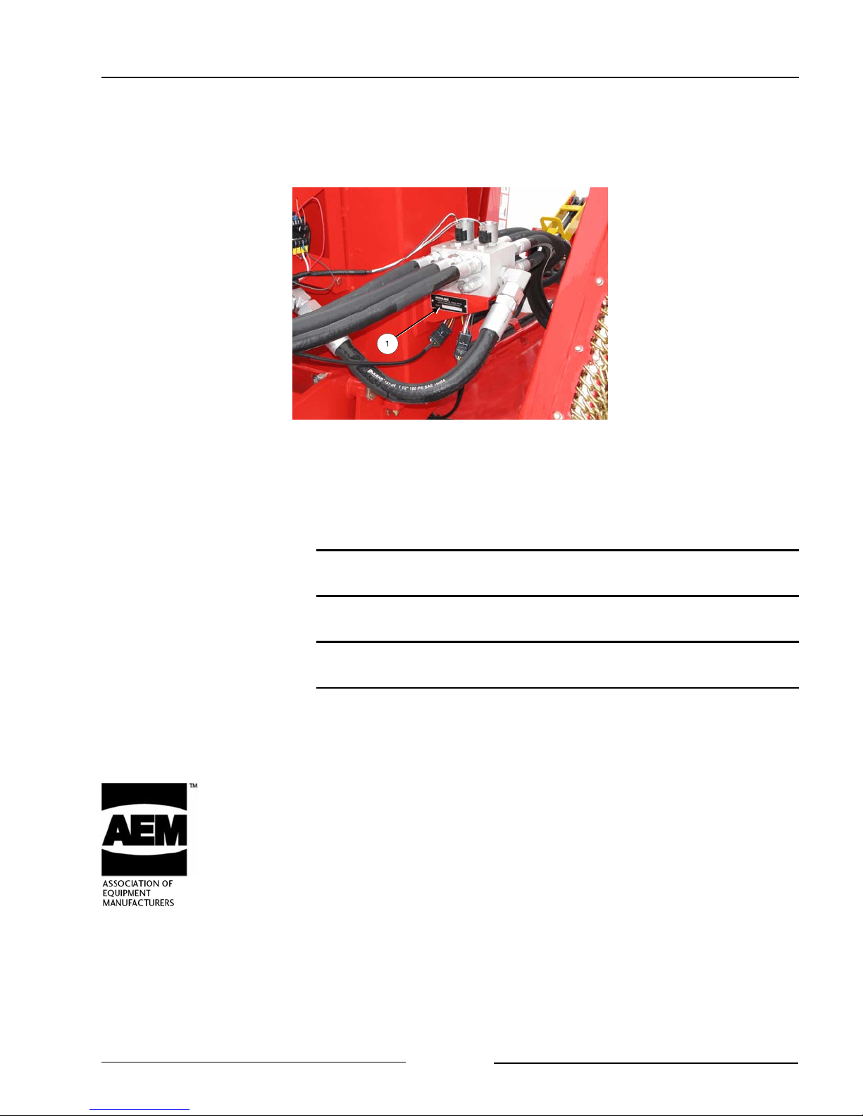
DO NOT OPERATE WITH SHIELDS MISSING
DO NOT CONTACT ROTATING BLADES
Rotating blades can cause serious injury or death.
Always disengage power take off, shut off tractor, remove key, set
park brake and wait for all parts to stop turning before servicing.
Keep guards in place and in good condition.
DO NOT OPERATE MOWER WITH WINGS RAISED
Contact with exposed rotating blades may cause injury or death.
Rotating blades may throw objects, causing injury or death
STAND CLEAR OF WINGS
Falling wings can cause serious injury or death.
Wing cylinders must be fully retracted and wing lock pins in place
before servicing.
Never stand under wings when lowering or raising.
Page 1-5
Section 1 - Safety
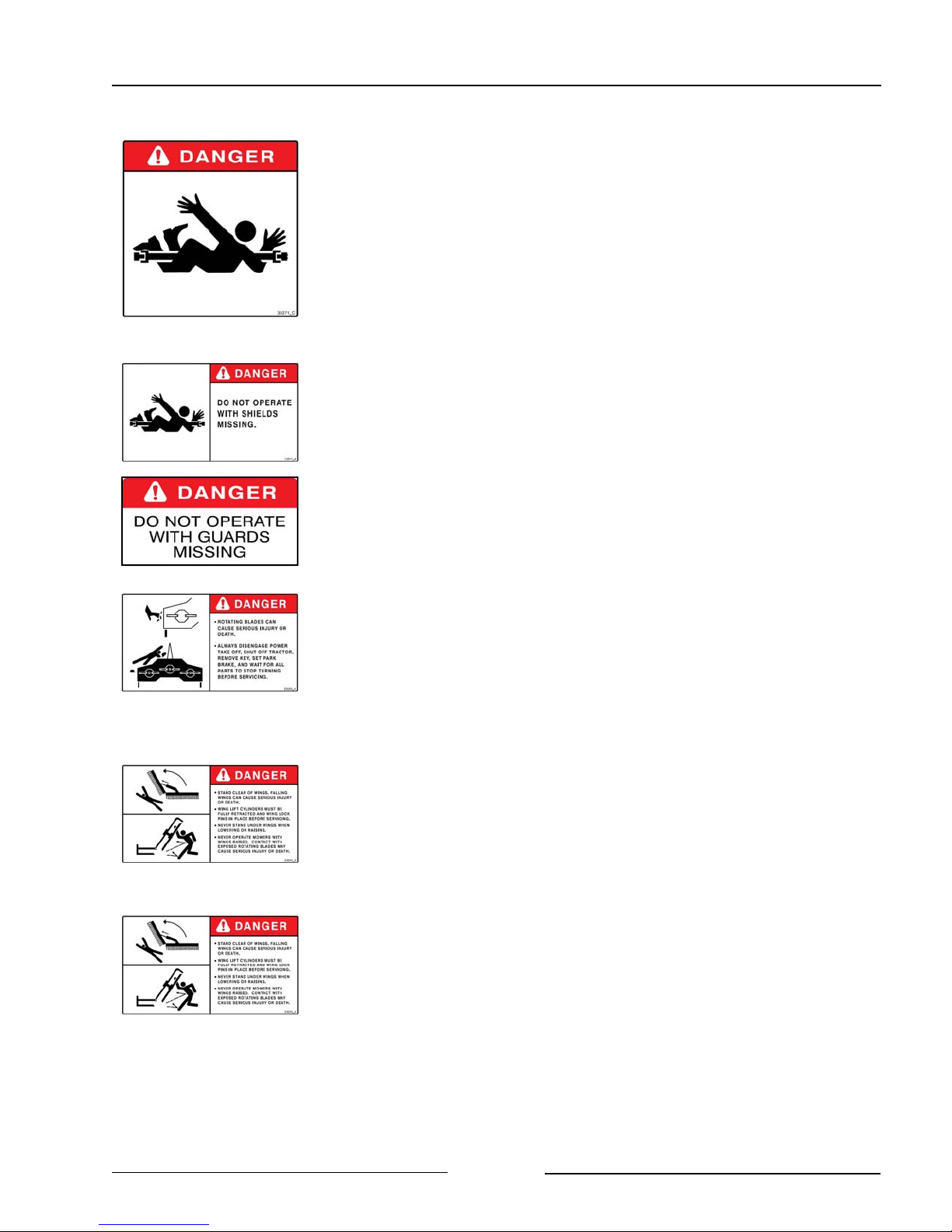
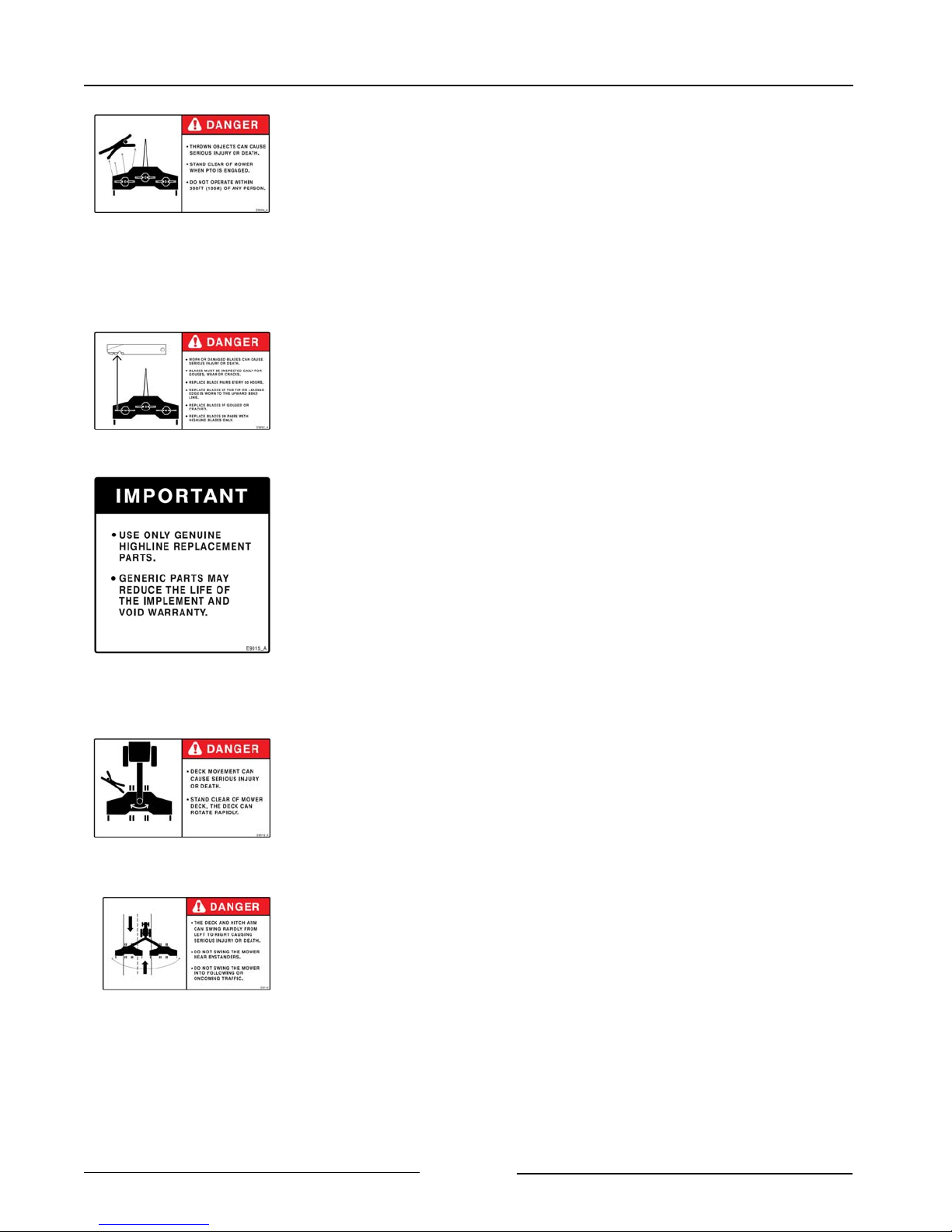
STAY BACK FROM MOWER IN OPERATION WHICH CAN
DISCHARGE OBJECTS SEVERAL HUNDREDS OF FEET
Thrown objects can cause serious injury or death.
Stand clear of mower when PTO is engaged.
Do not operate within 300 ft (100m) of any person.
Keep all shields and guards in place.
Clear mowing area of debris.
INSPECT BLADES FOR DAMAGE
Worn or damaged blades can cause serious injury or death.
Blades must be inspected daily for gouges, wear or cracks.
Replace blade pairs at maximum of 50 hours.
Replace the blade pair if the tip or leading edge is worn so that only
2" (51 mm) of the blade remains.
Replace blades if gouged or cracked.
Blades must be changed in sets.
Use only Highline replacement parts.
Do not repair blades.
STAND CLEAR OF ROTATING DECK
Contact with rotating deck can cause serious injury or death.
Stand clear of mower deck. Mower deck can rotate rapidly.
DO NOT SWING DECK AND HITCH ARM NEAR BYSTANDERS
OR INTO TRAFFIC
The deck and hitch arm can swing rapidly from left to right causing
serious injury or death.
Do not swing the mower near bystanders.
Do not swing the mower into following or oncoming traffic.
Page 1-6
Section 1 - Safety
ENSURE SLOW MOVING VEHICLE SIGN IS IN PLACE
Ensure the Slow Moving Vehicle sign is in place, clean and easily
visible.
Ensure the reflectors are in place, clean and easily visible.
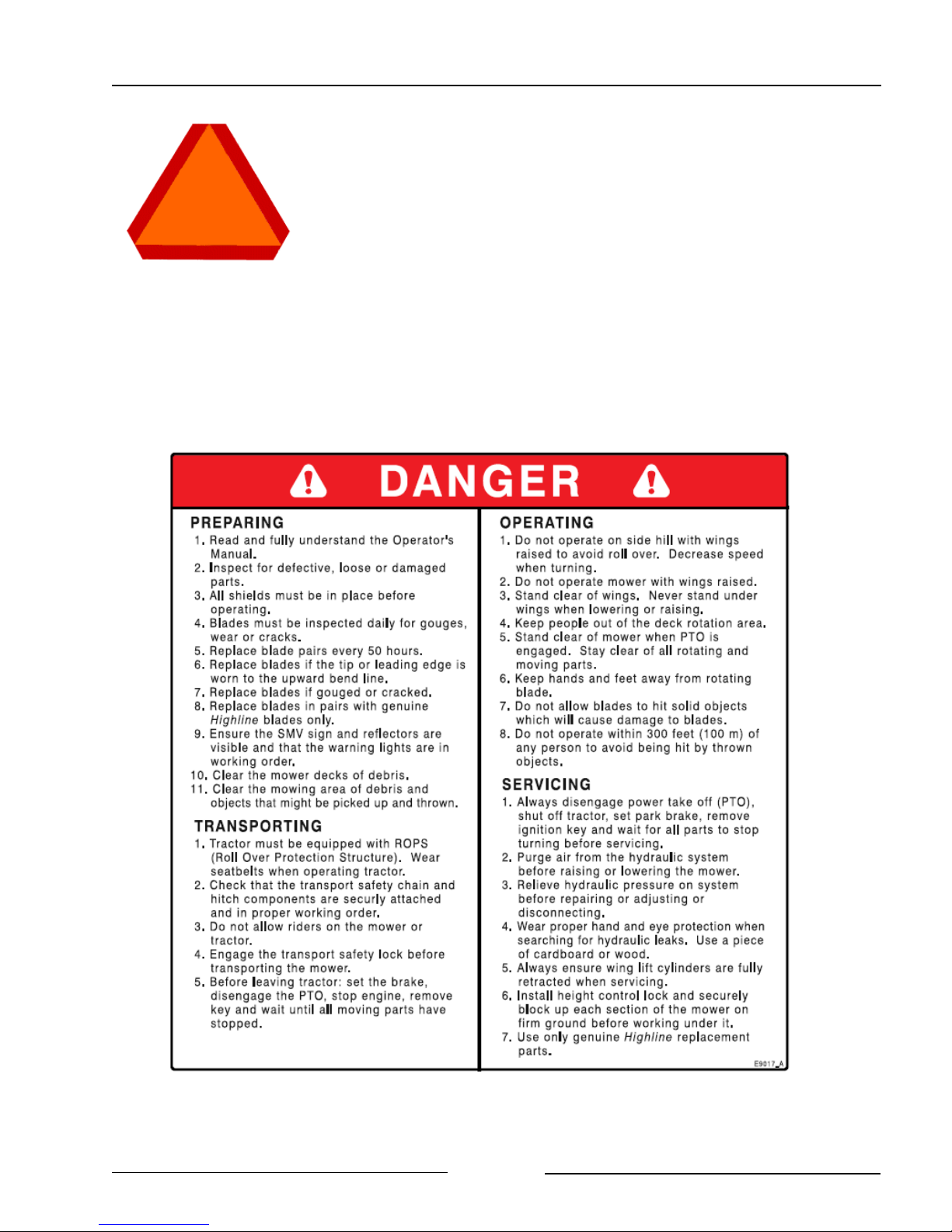
READ AND FULLY UNDERSTAND THE INSTRUCTIONS ON THIS DECAL
Page 1-7
Section 1 - Safety
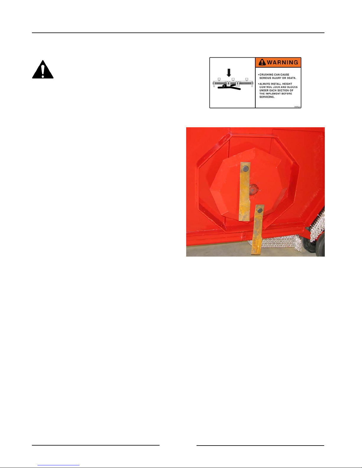
STAND CLEAR WHEN MOWER IS BEING RAISED OR
LOWERED
Crushing can cause serious injury or death.
Always install height control lock and blocks under each section of
the implement before servicing.
DO NOT OPERATE ON SIDE HILL WITH WINGS RAISED
Tractor or mower roll over can cause serious injury or death.
Tractor must be equipped with Roll Over Protection System.
(ROPS)
Always wear seat belts when operating tractor.
USE PAPER OR CARDBOARD TO CHECK FOR HYDRAULIC
LEAKS
To prevent serious injury or death:
Relieve pressure on hydraulic system before repairing, adjusting or
disconnecting.
Wear proper hand and eye protection when searching for leaks.
Use wood or cardboard instead of hands.
Keep all components in good repair.
KEEP MOWER DECK CLEAR OF DEBRIS
Fires can occur if dry material builds up on the mower deck.
Always ensure deck is kept clean.
A clean deck ensures optimum performance of wing lift and height
control.
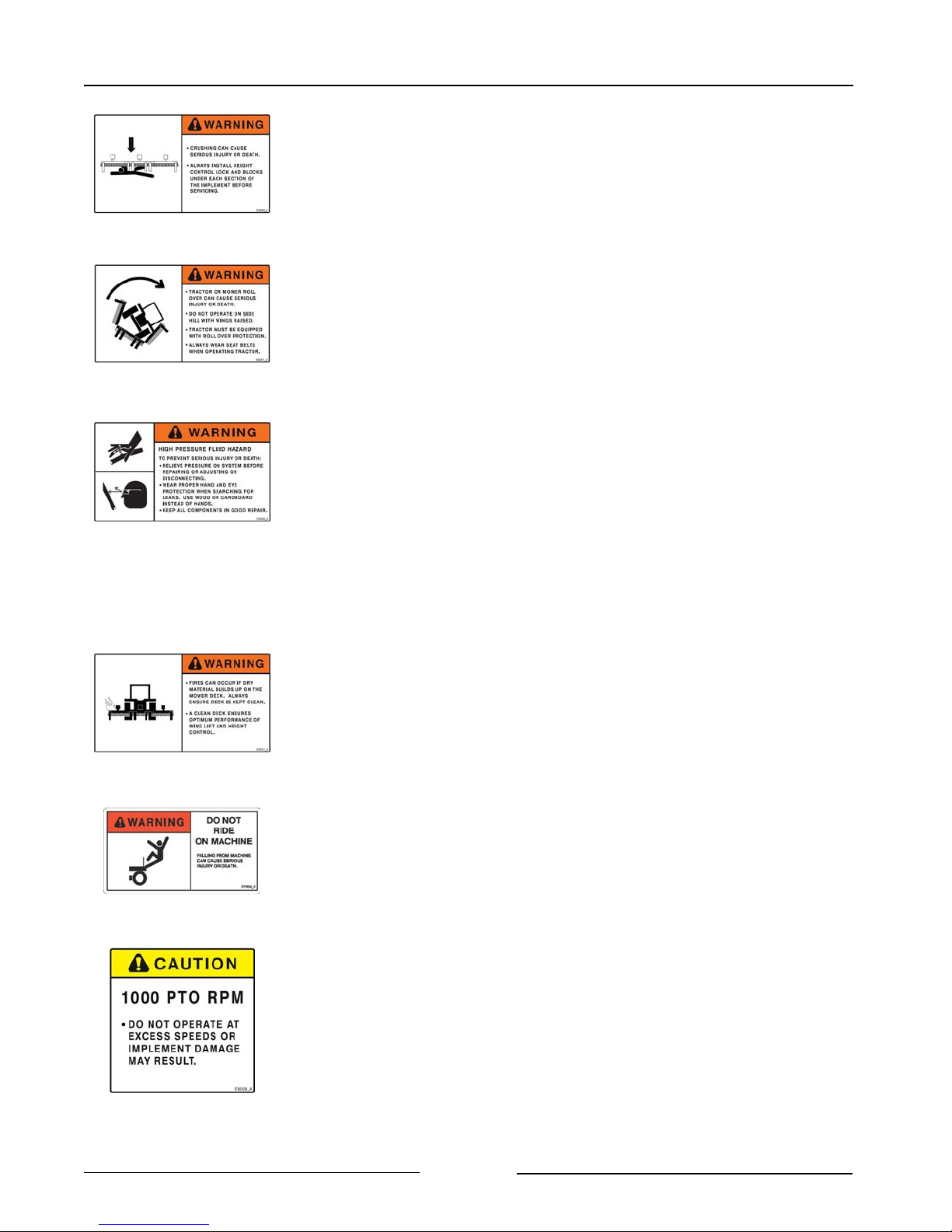
DO NOT RIDE ON MACHINE
Falling from the moving machine can cause serious injury or
death.
Falling from the operating machine can cause being entangled
under the machine or being injured by the machine.
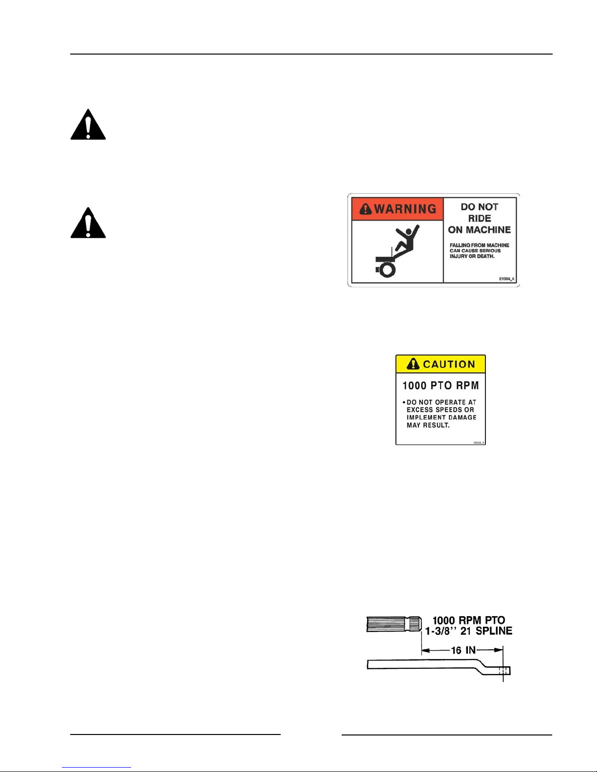
DO NOT EXCEED PTO SPEED
Do not operate at excess speeds or damage to the mower may
result.
Page 1-8

Section 1 - Safety
DO NOT TOUCH HOT SURFACES
Heat from the hydraulic oil causes surfaces to be hot.
Do not touch pump, motors, oil tank, oil cooler or hydraulic hoses
while using mower.
Allow a cool down time before touching or servicing these items.
Page 1-9
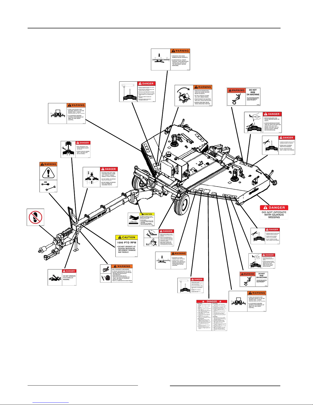
SAFETY DECAL LOCATIONS
Section 1 - Safety
Page 1-10
Section 2 - Transporting the Mower
2.0 TRANSPORTING THE MOWER
Only tow the mower behind a
properly sized and equipped
tractor which exceeds the weight
of the mower by 50%. Do not tow
the mower behind a truck or other
type of vehicle
Do not allow children or other
people to ride on the tractor or
mower. Falling off can result in
serious injury or death.
1. Tractor requirements.
- Roll Over Protection System (ROPS)
- Working seatbelts
- 1 3/8" 21 spline PTO
- Recommend 115 PTO HP
2. Ensure correct PTO speed.
- Ensure that the tractor PTO speed
matches the mower’s gearbox speed
of 1000 rpm.
- Do not attempt to operate the mower
at a different PTO speed.
3. Adjust tractor drawbar length.
- Set the drawbar length to 16" (406
mm) for a 1 3/8" 21 spline PTO.
- This length is measured from the tip of
the PTO shaft end to the center of the
drawbar hole. (Refer to your tractor’s
operator manual for drawbar
adjustment procedures.)
Note: To prevent damage to the tractor
drawbar, avoid traveling at high
speeds and over rough terrain.
Note: Do not use PTO adapters.
PTO adapters will cause a
driveline failure and possible
tractor damage. Your mower
warranty will also be invalid.
Tractor Drawbar Adjustment for 1000 RPM
108005
Page 2-1
Section 2 - Transporting the Mower
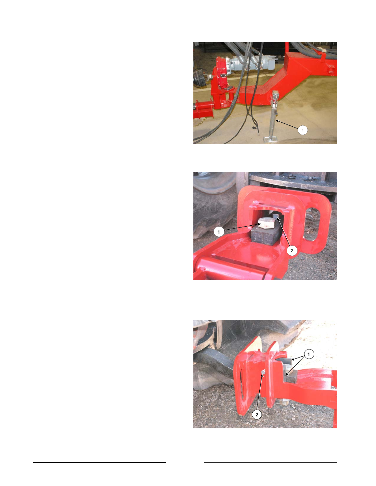
4. Lift the hitch.
- Lift the hitch arm with the jack (1).
- The hitch arm is very heavy. Do
not attempt to lift it without using
the jack.
- Adjust the hitch to connect the
drawbar.
5. Connect the hitch.
- Connect the tractor drawbar to the
drawbar connector with:
- 1 1/4" x 5" bolt, washer, locknut
and nut (1). Torque to 600 lbf (813
Nm)
- 3/4" x 3½" bolt,washer, lockwasher
and nut (2). Torque to 260 lbf (352
Nm).
- Place a ½" thick shim plate (1) on
each side of the drawbar and fasten in
place with 3/8" x 5" bolt and locknut
(2 ).
Lift Hitch with Jack
Connecting Drawbar Connector
213044C
107082C
Page 2-2
Drawbar Shims
107083C
Section 2 - Transporting the Mower
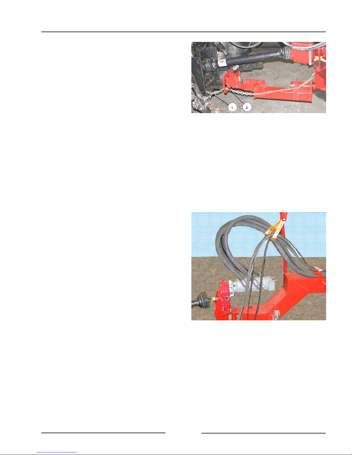
6. Connect the safety chain to the tractor.
- Ensure the safety chain rating is equal
or greater than the gross weight of the
mower.
- Route the safety chain (1) through the
large slot (2) in the drawbar
connector. Securely fasten the chain
to the tractor and lock in place with the
hook lock.
7. Tractor wheel tread width settings.
- Increase the tractor rear wheel widths
to maintain tractor stability when
working on inclines or rough ground.
Connect the Safety Chain
108167C
8. Route the hydraulic hoses and wiring
harness through the hose support arm.
Route Hoses Through Holder
214034
Page 2-3
Section 2 - Transporting the Mower
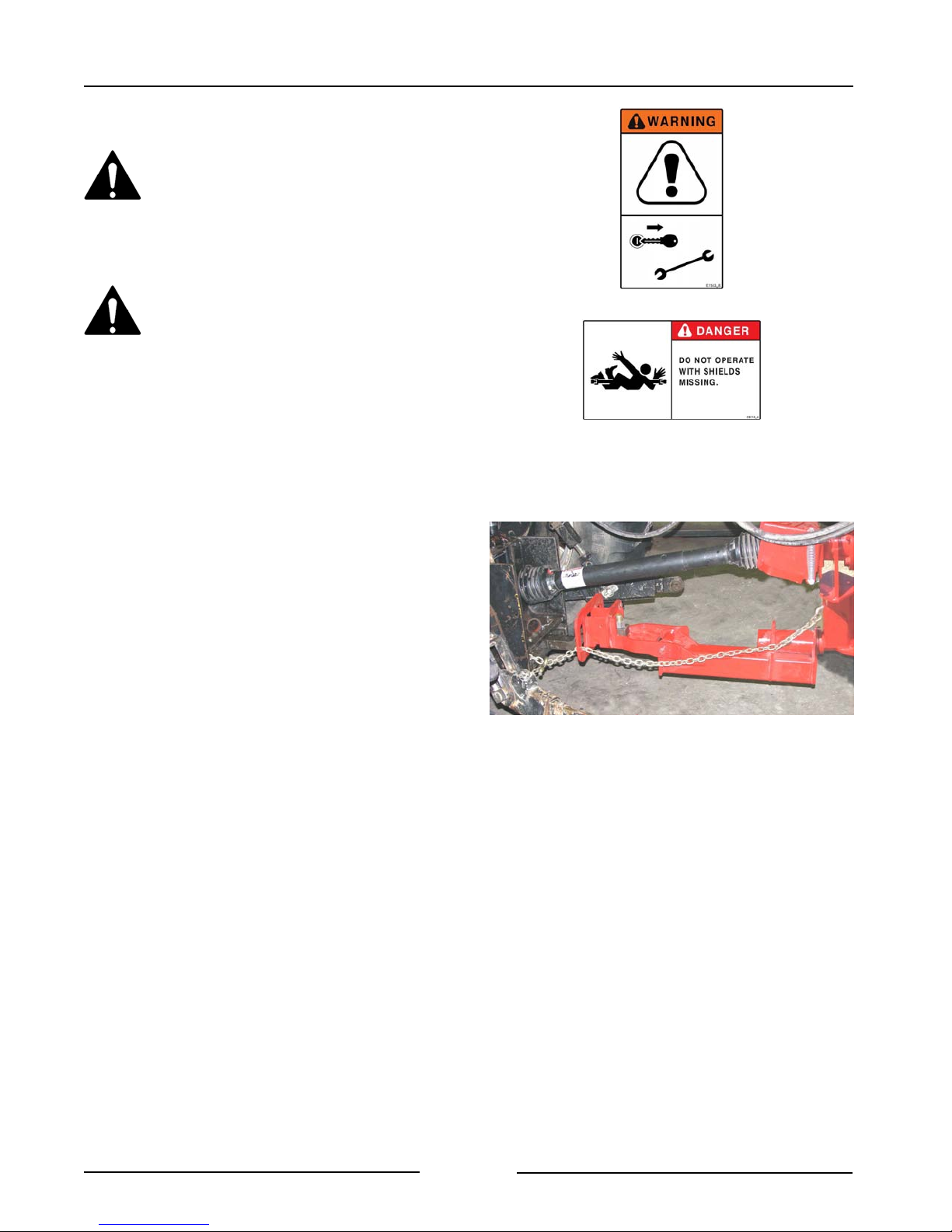
9. Attach the driveline to the PTO.
Shut off the tractor engine before
attaching PTO driveline.
Entanglement in the rotating
driveline can cause serious injury
or death.
The mower shall not be operated
without the driveline shields in
place.
- Shut off the tractor engine and
remove the key.
- Check that the driveline telescopes
easily and that the shields are in good
condition and rotate freely.
- Lift the tractor PTO shield.
- Support the driveline, pull back on the
yoke collar, align the splines by
rotating the mower driveline and push
the driveline into the tractor PTO shaft
until the collar snaps into place.
- Push and pull the yoke several times
to ensure the driveline is locked. Do
not pull on the collar as this will
release the lock.
- Lower the tractor & hitch PTO shields
into place.
Attach Driveline to PTO
108167
Page 2-4
Section 2 - Transporting the Mower
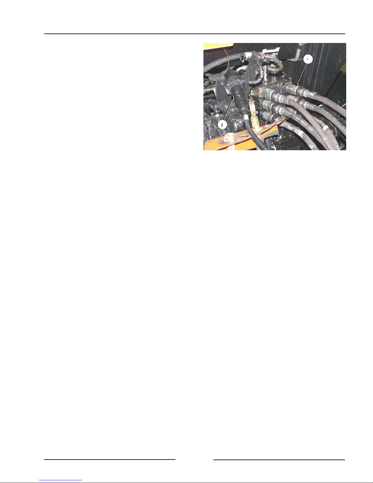
10. Attach the hydraulics.
The mower requires 3 remote connections.
- If the optional joystick is included, then
only 1 remote connection is required.
- For the joystick option, the
hydraulic lever will work in only
one direction. There is a check
valve on the valve manifold. If the
hydraulics are not working, move
the lever in the opposite direction.
- Clean the end of the hoses (1) and
the connection.
- Firmly push the hoses into the tractor
receptacle according to user
preference.
Attach Hydraulics and Lighting
108008C
- Route the hoses so they do not
interfere with moving parts.
11. Connect the lights.
- Connect the light plug (2) into the
appropriate tractor receptacle.
- Ensure the light cable does not
interfere with or contact moving parts.
12. If the optional joystick is on the
machine, route the joystick cable.
- Ensure the cable does not interfere
with or contact moving parts.
13. Place the hitch jack in the storage
location.
Page 2-5
Section 2 - Transporting the Mower
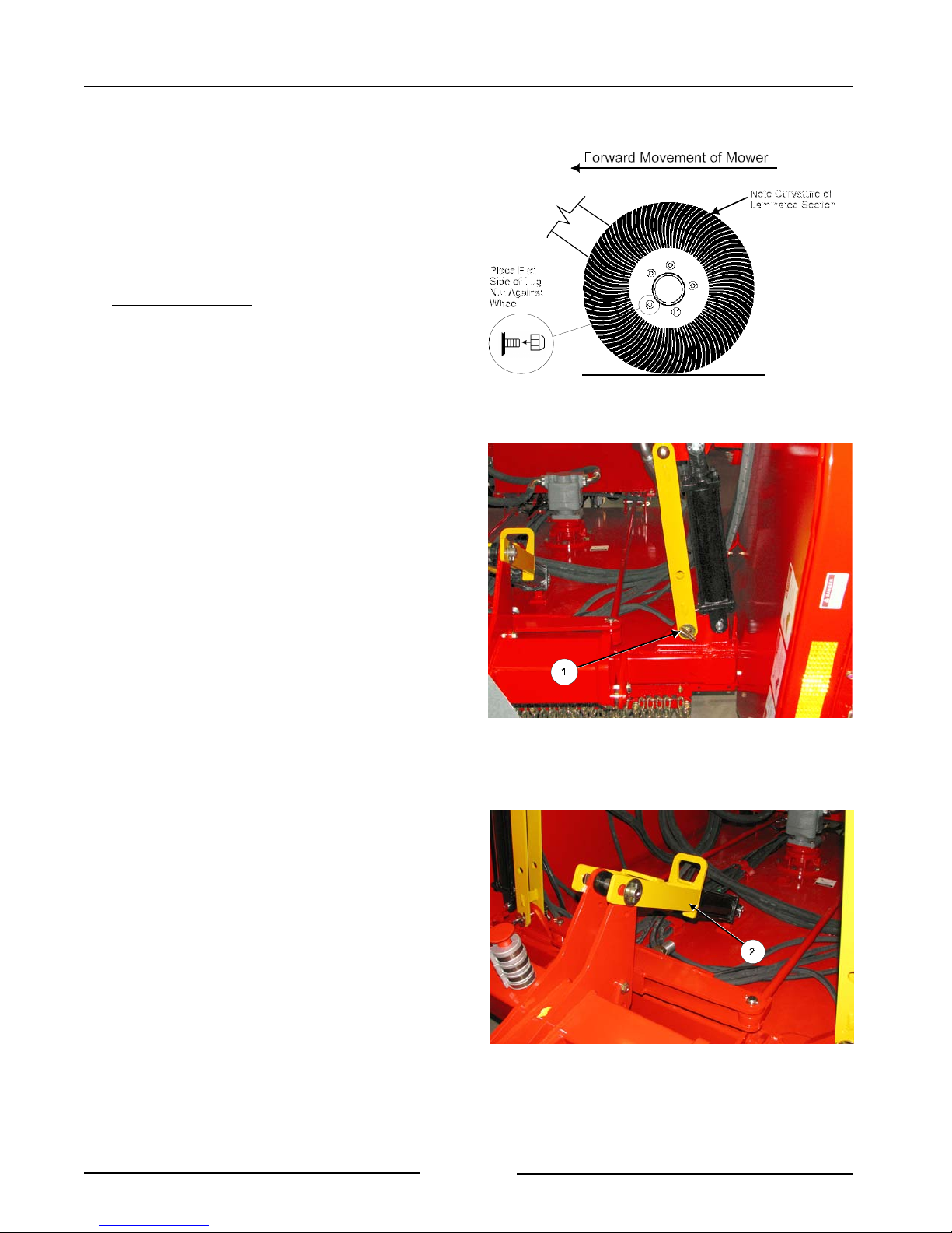
14. Check on the condition of all the tires.
- Ensure that the lug nuts have the flat
side of the lug nut against the wheel
rim.
- Torque the lug nuts to 75 lbf (101
Nm).
Laminated Tires:
! Do not transport the mower on
roadways for long distances with
laminated tires.
15. Raise the wings until they rest in
place.
Laminated Tires
107074C
16. Install the wing transport lock pins (1)
on both wings and clip the pins into
place.
17. Lower the mower until the hydraulic
height control cylinder is resting on the
height cylinder transport lock (2).
Install the Wing Transport Lock Pins
216047C
Page 2-6
Height Cylinder Resting on Transport Lock
216048C
Section 2 - Transporting the Mower
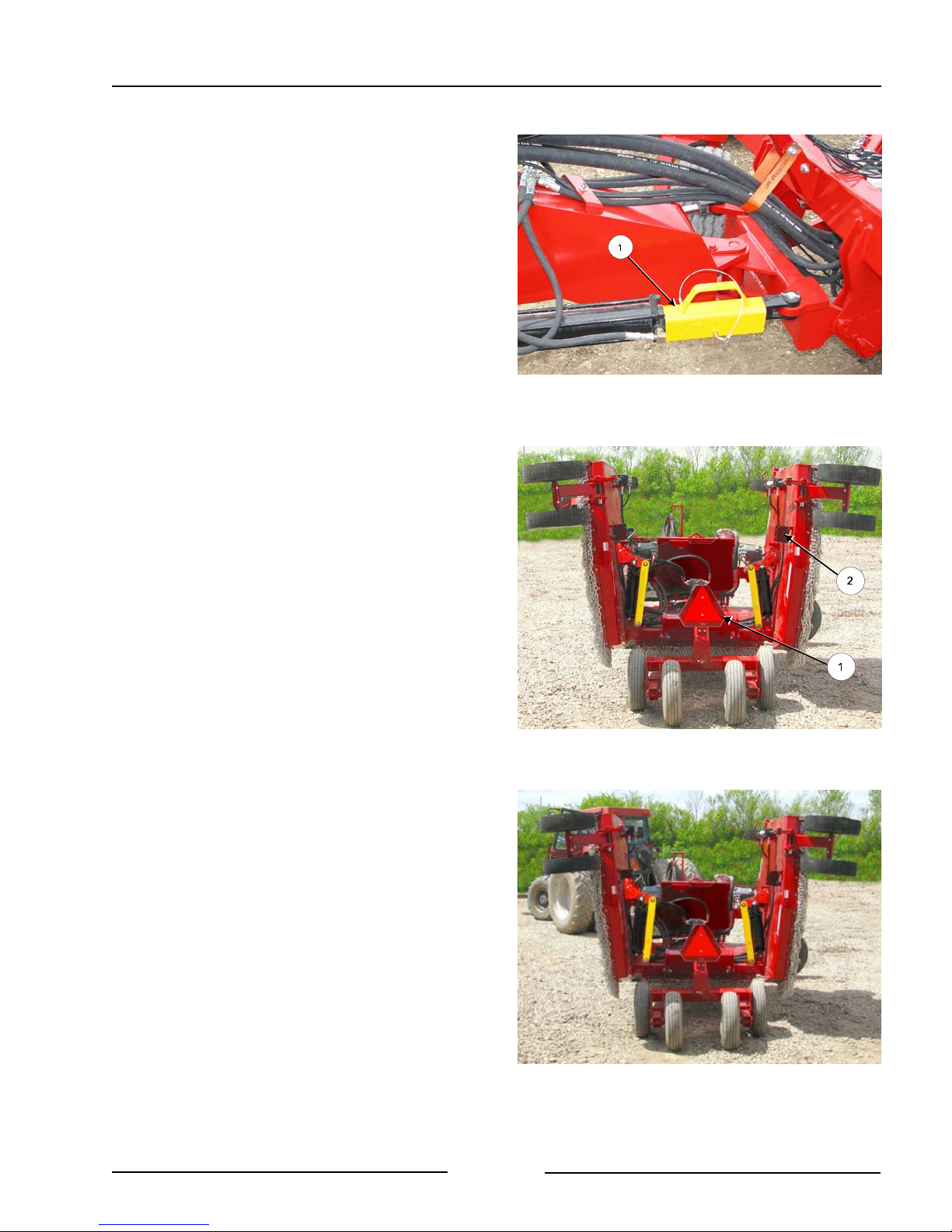
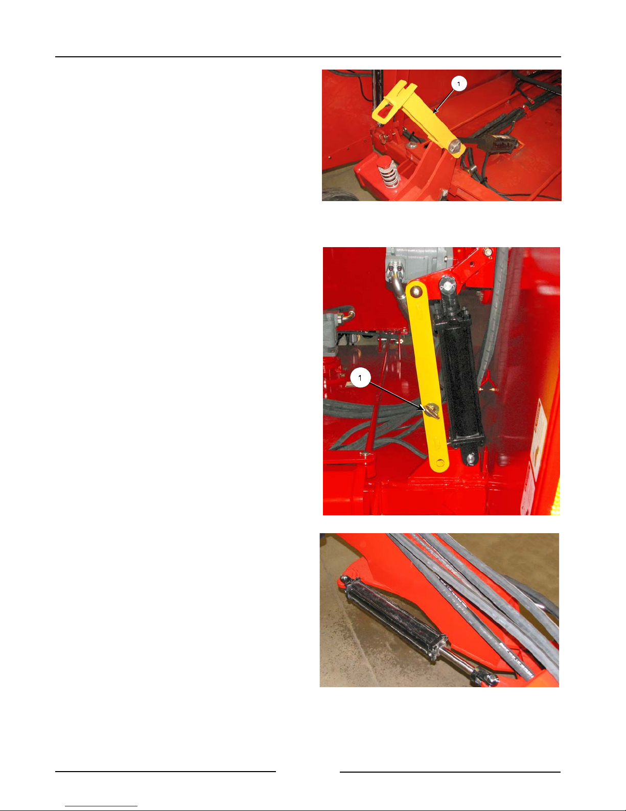
18. Install the hitch transport locks (1)
over both hitch hydraulic cylinders and
pin into place.
19. Ensure that the Slow Moving Vehicle
(SMV) sign (1) is clean and visible.
20. Ensure that the taillights (2) are clean,
visible and in good working order.
21. Transport speed.
Hitch Transport Locks
Ensure SMV is Visible & Lights are Working
214067C
214107C
- Do not exceed 20 mph (32 km/h).
Page 2-7
Transport Speed
214106

Section 2 - Transporting the Mower
This Page Left Blank
Page 2-8
Section 3 - Mower Preparation
3.0 MOWER PREPARATION
1. Park the tractor and mower on level
ground.
- Engage the tractor parking brake.
2. Ensure that all decals are clean and in
place.
3. Ensure that the Slow Moving Vehicle
(SMV) sign is clean and visible.
4. Ensure the lighting is working properly.
5. Connect the electrical power for the
mower to an outlet that is rated for 30
amps or more to ensure sufficient power
for the cooling fan.
- The power can also be taken directly
from the tractor battery.
Clean SMV and Lights
214107
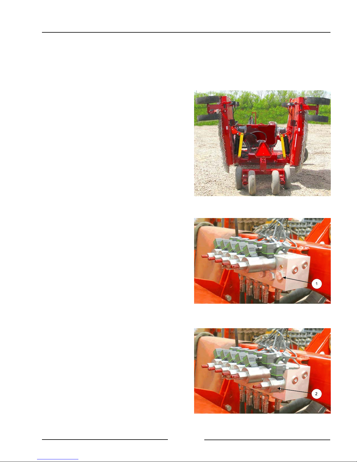
6. For mowers with the optional joystick
control, confirm that the hydraulic control
block is configured for the type of circuit
that is on the tractor.
- If the tractor has a Closed-loop circuit,
then the mower control block should
have a plug (1) in the last port.
- If tractor has an Open-loop circuit,
- Remove the plug from the mower
control block.
- Install the solenoid valve (2) that
came with the joystick.
- Connect the wiring harness
connector marked “F1".
If the mower will be used with both open-loop
system and closed-loop system tractors, then
run the control block with the solenoid valve
installed.
Block with Plug - Closed Loop Tractors
Block with Solenoid - Open Loop Tractors
214118C
214119C
Page 3-1
Section 3 - Mower Preparation
7. Check the condition of the blade pans.
Securely block-up the mower
before any work is done under the
mower when lifted up. This is to
prevent the mower from dropping
due to inadvertent operation of
controls, hydraulic leaking or
failure of any components.
- Clean debris and material buildup
from the blade pan area and from the
pans.
- Check that no wire or other materials
are wrapped around the shaft or pan.
- Inspect the pan for damage caused by
contact with an object.
- Inspect blade pan mounting hardware
for damage.
- Inspect blade mounting bolts for
damage.
Inspect Blades & Hardware
201059
Page 3-2

Section 3 - Mower Preparation
8. Check the condition of the blades.
- Inspect the blades daily.
- Check that the blades swing freely.
Note: Do not sharpen the blades.
Replace them with Highline
blades.
! Replace the blade pair at a maximum
of 50 hours regardless of the wear
because of the possibility of metal
fatigue and non-visible cracks in the
blades. Replace with Highline blades.
! Replace the blade pair if the tip or
leading edge is worn so that only 2"
(51 mm) of the blade remains.
Replace with Highline blades.
! Replace the blade pair if a blade is
gouged, has visible cracks or is bent.
Replace with Highline blades.
Replace blades in pairs with only
Highline blades.
-See “Blade Replacement
Procedure” in the Maintenance
Section.
Replace Blade When Tip/Leading Edge Worn
Replace Blade When Gouged
1070802C
107080
Page 3-3
Section 3 - Mower Preparation
6. Lift the height control transport lock.
- Raise the mower center section by
extending the lift cylinder.
- Shut off the tractor and remove the
ignition key.
- Lift the height control cylinder lock (1).
7. Remove the wing transport lock pins.
- Place the pins into the pin storage
position (1).
Lift the Height Control Transport Lock
216009C
8. Remove the hitch transport locks from the
hitch cylinders.
- Store the transport locks in the
toolbox.
Remove Hitch Cylinder Locks
Page 3-4
Remove Wing Transport Lock Pins
216049C
214039
Section 3 - Mower Preparation
9. Lower the wings on level ground.
10. Level the mower center section deck
front to back.
Note: Do this procedure on level ground.
- Raise the mower to full height by
extending the height cylinders.
Hold the lever for a few seconds to
ensure the phasing cylinders are
synchronized.
- Lower the mower to the preferred
cutting height.
Height from Front Wing Pivot to Ground
201061
- Measure the left side from the
center of the front wing pivot to the
ground.
- Verify this measurement at the
left back wing pivot to the
ground.
- Compare this height to the right
front and the right back at the
center of the wing pivots to the
ground.
Height from Back Wing Pivot to Ground
201062
Page 3-5

Section 3 - Mower Preparation
- Use the level adjuster near the rear center lift cylinder to adjust the center section for
front to back level.
Note: The tie rod does not adjust for left to right leveling of the center deck. The rear
wheels are on pivot joints to allow for right to left self-levelling.
- Loosen the tie rod jam nut (1).
- Turn the adjuster nut (2) to raise or
lower the center rear wheels.
- To lower the mower, loosen the
adjuster nut.
- To raise the mower, tighten the
adjuster nut.
- Tighten the tie rod jam nut (1) to lock
in place.
- Measure and compare the level from
the front to back.
- Adjust further if required.
Level Adjuster & Jam Nut
214040C
Page 3-6

Section 3 - Mower Preparation
Primary Mowing Operating Conditions
There are 2 primary operating conditions:
- Mowing on Slopes such as roadway ditches when traveling with traffic.
- Mowing on Level Ground.
11. Verify the blade direction rotation.
! Direction of blade rotation is indicated by decals near the motor on the deck of the center
and wing sections.
- Verify that the blades turn in the direction of the decal.
- Verify that the leading edge of the blade moves into the direction of rotation.
! Compare the blade directions to the diagram below.
RCH Hydro 15 Foot RCH Hydro 10 Foot
Blade Direction for Right Hand Slope or
Level Ground
107106
Blade Direction for Right Hand Slope or
Level Ground
108225R
Page 3-7

Section 3 - Mower Preparation
13. Determine the wing height adjustment.
15 Foot Mower
! Slope Operation
- Confirm the Wing Height
according to the diagram.
- As needed, use the Wing
Adjustment Procedure (listed
below):
- Raise the outer edge of the left
wing (road side) ½" (12 mm) up
from the leveled center section.
- Lower the outer edge of the
right wing (ditch side) ½"
(12mm) down from the leveled
center section.
- This will enable the wings to
contour to the ditch.
|»Roadway
Wing Adjustment for Slopes- From Behind
107016
! Level Ground Operation
- Confirm the Wing Height
according to the diagram.
- As needed, use the Wing
Adjustment Procedure (listed
below) to level the left wing and
right wing with the leveled
center section.
Level Ground Wing Adjustment - From Behind
107101
Page 3-8

Section 3 - Mower Preparation
10 Foot Mower
! Slope Operation
- Confirm the Wing Height
according to the diagram.
- As needed, use the Wing
Adjustment Procedure (listed
below):
- Lower the outer edge of the
right wing (ditch side) ½"
(12mm) down from the leveled
center section.
- This will enable the wings to
contour to the ditch.
! Level Ground Operation
- Confirm the Wing Height
according to the diagram.
- Right Wing - level with the center
section.
- As needed, use the Wing
Adjustment Procedure(see below).
|»Roadway
Wing Adjustment for Slopes - From Behind
Level Ground Wing Adjustment - From Behind
108169
215072
Page 3-9

Section 3 - Mower Preparation
13. Wing height adjustment procedure.
Note: Level the center section before adjusting wing height.
- Fully raise the mower by extending the
lift cylinders. Hold the lever open for
30 seconds or until the phasing
cylinders are synchronized.
- On a level surface, lower the mower to
the preferred cutting height.
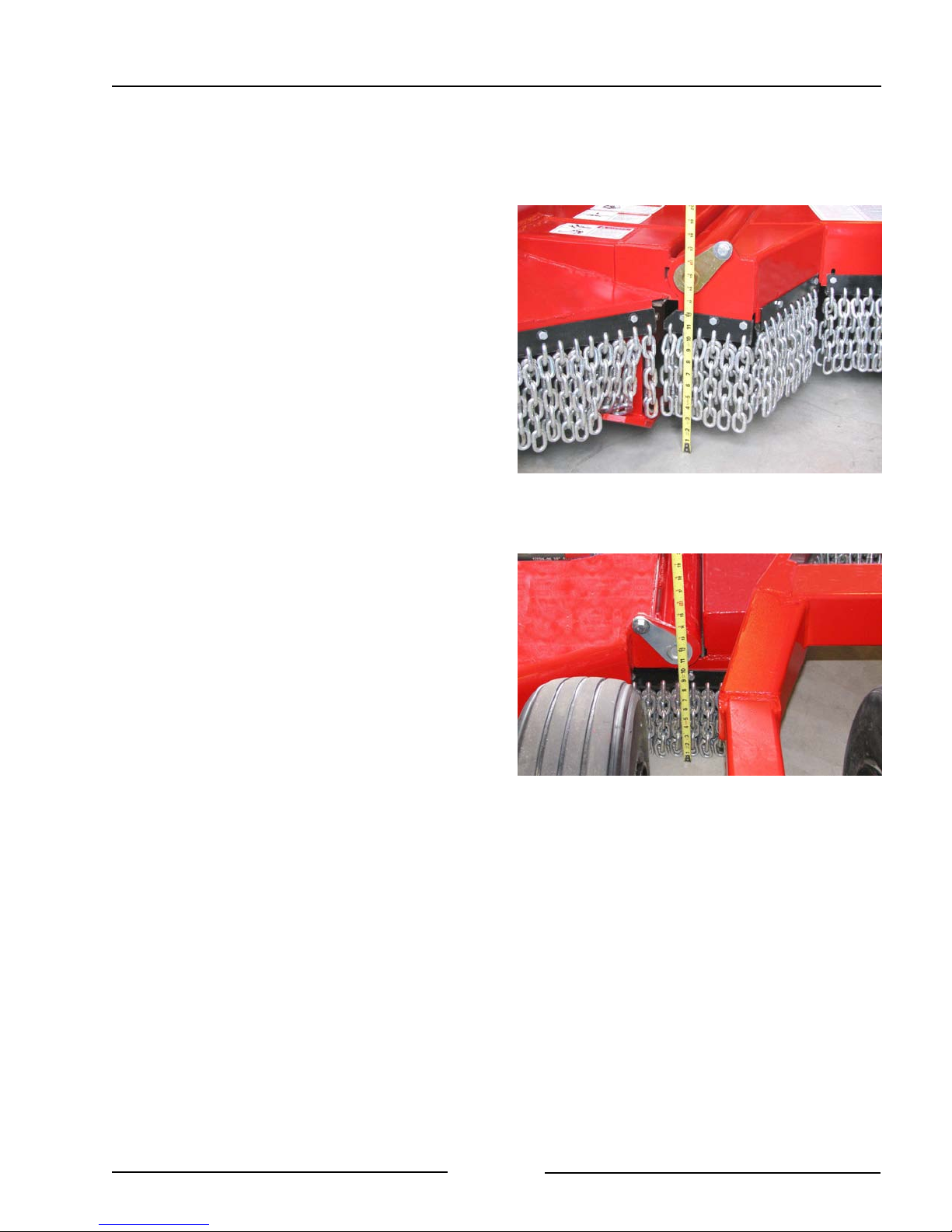
- On one wing, measure the height from
the top of the chain mount strap near
the center section (1) to level ground.
Compare the measurement to a
location on the outer wing section (2).
Measure Wing Heights
107032C
- Loosen the wing height adjustment
jam nut (1).
- Adjust the height of the wing using
the adjustment nut (2).
- Use the Wing Height Adjustment
diagram (shown above) for the
heights.
- Measure and compare.
- Tighten the jam nut (1).
- Repeat the procedure on the other
wing.
Adjust Wing Height
214137C
Page 3-10

Section 3 - Mower Preparation
14. Set the preferred cutting height.
- Lower the wings.
- Raise the mower to the preferred
cutting height.
- Install height stops (1) around the
cylinder rod to maintain the
preferred cutting height
15. Inspect all the hydraulic cylinders,
pump, motors and hoses.
Use a piece of cardboard or
heavy paper to check for leaks.
Do not use your hand. Wear
proper hand and eye protection
when searching for leaks.
Relieve pressure on the hydraulic
system before repairing, adjusting
or disconnecting.
Height Stops Installed
214041C
- Check for hydraulic leaks along the
hydraulic lines and at the tractor.
- Ensure the proper size pins are in
place and secured.
Page 3-11
Inspect Hydraulic Components and Hoses
214107

Section 3 - Mower Preparation
16. Clear debris from the removable chaff
screen.
- Remove the screen to clean the both
sides of the screen.
- Use a broom, low pressure air and
water to clean the screen.
17. With the chaff screen removed, clear
the debris from the oil cooling tank
and the radiator.
- Use a broom and a low pressure air
hose to remove the debris.
18. Clear debris from the fan on the
backside of the oil tank .
Clear Debris from the Chaff Screen
Clear Debris from Radiator
216050
216051
Note: When the fan initially starts up, the
fan will blow in reverse for a short
time to remove some of the debris
in the radiator.
- If additional material needs to be
removed, blow air through the fan and
through the radiator.
- If dirt is stuck in the fins or core of the
radiator, clean out with a low pressure
water hose.
Clear Debris from Fan
Page 3-12
216052

Section 3 - Mower Preparation
19. Check the oil level in the oil tank.
Maintaining a proper level of oil is very
important in the operation of the mower.
- When the oil is cold, check that the oil
level is showing in the middle of the
sight glass (1) which is on the side of
the oil tank.
Low Oil Level
Low oil level in the tank is caused by a
leakage of oil. Locate the leak at once. Loss
of oil can cause severe damage to the
hydraulic pump and motors.
- To fill the oil tank
- Clean the top of the tank to
prevent contamination of the oil.
- Remove the top breather cap (2)
and fill with hydraulic oil until the
oil level is showing in the middle of
the sight glass (1).
Check the Oil Level in the Tank
216053C
Note: Do not fill the tank to more than
the middle of the sight glass to
allow room for the oil to expand
as it heats up.
Note: It is important to only use clean
filtered oil when filling the oil.
Clean oil will assist the pump
and motors to work more
efficiently.
- Clean the breather cap (2) and
replace the cap on the tank.
Page 3-13

Section 3 - Mower Preparation
20. Ensure the shutoff valves (3) at the
bottom of the tank are in the open
position.
21. Check the oil filter operating pressure.
- When the oil is warm, with the pump
running, check the filter pressure
gauge (1).
Note: When the oil is cold, the gauge
may show that the filter needs
replacing. Allow the oil to warm
and check the filter gauge again.
- If the gauge is in the green zone, the
filter is okay.
- If the gauge is in the yellow zone, the
filter will need to be replaced soon.
- If the gauge is in the red zone, replace
the filter immediately.
Open Tank Shutoff Valves
Check Oil Filter Operating Pressure
214044C
216054C
Note: See Section 5 “Maintenance” for
information on “Replacing the
Filter”.
Page 3-14

Section 3 - Mower Preparation
22. Check the oil level in the pump
gearbox.
- Remove the breather vent (1) at the
top of the gearbox. The breather has
a dip stick attached to it.
- Check that the oil is at least to the
level of the line near the bottom of the
dip stick.
- If needed, add oil using 85W90 gear
oil.
- Replace the breather vent (1).
Check Oil Level in Pump Gearbox
214045C
Page 3-15

Section 3 - Mower Preparation
23. Check the condition of the chain
guards all around the machine.
The mower shall not be operated
without the chain guards in place
or in good condition.
- Replace worn, missing or broken
chain sections immediately.
24. Inspect the wheels and tires for
damage or foreign objects. Repair or
replace as necessary.
25. Inspect the wing skid plate for secure
mounting and wear.
The mower shall not be operated
without the skid plates in place.
- If the leading edge (1) of the wing skid
plate is worn excessively or is
damaged, it should be replaced.
Check Condition of the Chain Guards
Inspect Wing Skid Plates
214046
214047C
26. Inspect the center section skid plate
(behind the front chain guards) for
secure mounting and wear.
Inspect the Center Section Plates
Page 3-16
214048

Section 3 - Mower Preparation
27. If the wing skid plate wheel is
installed, check the condition of the
tire and that all fasteners are tight.
28. For 10 Foot Models, inspect the
center deck skid and counterweights
for secure mounting.
Inspect Wing Skid Plate Wheel
Inspect Center Skid & Counterweights (10 Foot)
214049
215073
Page 3-17

Section 3 - Mower Preparation
29. Ensure the driveline is securely
attached to the pump gearbox.
30. Ensure the driveline shields are
lowered into place and are in good
repair to prevent injuries.
The mower shall not be operated
without the driveline shields in
place.
31. Lubricate all grease fittings and check
the fluid level in the pump gearbox.
See the Maintenance Section.
32. Ensure all fasteners are tightened.
Driveline Fastened to Gearbox
214050
Page 3-18

Section 4 - Operating the Mower
4.0 OPERATING THE MOWER
Do not allow anyone to ride on the
mower.
- Falling from the machine can
cause injury
Do not operate mower blade pan on
the wings that are raised.
- Contact with exposed rotating
blades can cause serious injury or
death.
- Raised wings can throw objects
causing serious injury or death.
Hydraulic Oil Temperature
Cold Oil
When the oil temperature is low (ie. during
cool weather operation - below 32"F/0"C) it is
recommended to rotate the pump and motors
at a moderate speed (less than 1000 rpm) to
allow the oil to warm.
Cold oil may cause the filter to show that it
needs attention. When the oil warms, the oil
filter reading will return to normal.
Normal Oil Temperature
The typical temperature of the oil at the
motors is between 150 -160 "F (65 - 71 " C).
The fan at the radiator turns on at 150 "F (65
"
C).
Note: This is the factory setting but it
may be adjusted to another
temperature. See Section 7
“Troubleshooting” for more
information.
Note: An infrared heat sensor is a
valuable tool in knowing the
condition of the hydraulic system
and valuable for troubleshooting.
Page 4-1

Section 4 - Operating the Mower
Overheated Oil
If the oil temperature is too hot, damage to
the pump and motors may occur. It is
important to keep the oil cooler radiator clean
for heat to be removed from the oil.
When the “Oil Temp Warning” light comes on
at the switch box in the cab, it indicates the
oil temperature has reached 185" F (85" C).
When 185" F (85" C) oil temperature has
been reached, the wing motors will also stop
turning to indicate the high temperature
condition.
- Stop the mower immediately.
- Clean the radiator.
- Ensure the cooling fan is working.
Check the fuse that is located in the
power supply cable running to the
control box.
- Check that the electrical supply cable
is connected to an outlet that is rated
for 30 amps or more. The power can
also be taken directly from the tractor
battery.
Also check the “Troubleshooting” Section of
for additional directions.
Oil Temperature Warning Lamp
214052
1. Park on level ground.
2. Move both wing transport lock pins (1) to
the storage position on the wing lock
bars.
Page 4-2
Move the Wing Transport Lock Pins
216049C

Section 4 - Operating the Mower
3. Remove the hitch cylinder transport locks
from the cylinders.
- Store the locks in the toolbox.
4. Lower the wings.
Ensure all bystanders are well
clear of the wing movement area.
- Ensure the tractor PTO drive is
disengaged.
5. Remove debris from the cutting area.
- Mark areas where objects could cause
damage to the mower blades or pans.
Remove Hitch Cylinder Transport Locks
214039
Page 4-3

Section 4 - Operating the Mower
Controlling the Mower
The hydraulic pump on the hitch is driven by
the PTO driveline. The pump provides
hydraulic flow for the blade pan motors
mounted on the decks.
The flow for the hydraulic cylinders is
provided by the tractor hydraulics.
There are 2 types of controllers for the
mower:
- Control box requiring 3 tractor
hydraulic remotes.
- Control box with joystick requiring 1
tractor hydraulic remote.
Center Deck Blade Pan
When the hydraulic pump is being turned by
the PTO, the center deck blade pan will be
turning with both types of controllers.
Note: The wing deck blade pans will also
turn unless the RH Deck and LH
deck switches on the Control Box.
are in the “Off” position.
Control Box - 3 Remote Tractor
High Oil Temperature Warning
When the "Oil Temp Warning" light comes
on, it indicates the oil temperature has
reached the maximum temperature of 185" F
(85"C).
When 185" F (85"C) oil temperature has
been reached, the wing motors will also stop
turning to indicate the high temperature
condition.
Refer to “Responding to a High Oil
Temperature Warning” in this section.
Control Box for 3 Remote Tractor
42723_E
Also check the "Troubleshooting" Section
7 for additional directions regarding high
oil temperature.
Page 4-4

Section 4 - Operating the Mower
Wing Lift
This switch setting activates the wing lift
circuit.
Wing Lift LH or RH
When the Wing Lift switch is activated, this
switch allows the choice of which wing is to
be lifted when the hydraulic control lever is
moved.
Wing Deck Blade Pan Switches
To have the wing deck blade pans turning,
move the switches up.
Note: The deck blade pans will be
activated when the light on the
switch is on. If the light is off, the
deck blade pan is turned off.
Control Box for 3 Remote Tractor
42723_E
- To turn off one of the deck blade pans
move the switch down. This will
activate a solenoid valve that will cut
off the oil flow to the motor. The light
on the switch will be off.
Gradient Control (Steering Option)
If the mower has the optional Gradient
Control installed, the switch will activate the
hydraulic control lever to move the front
wheels so the mower tries to climbs the ditch.
This reduces the side force loads on the
tractor and also helps the mower to track
straight which improves the cutting.
- Turn on the switch on the control box.
- Activate the hydraulic control lever to
move the hydraulic cylinder to direct
the front wheels.
- Disengage the hydraulic cylinder when
wanting to turn or maneuver the
mower. This will allow the wheels to
castor.
Page 4-5

Section 4 - Operating the Mower
Control Box - Joystick Control (1 Remote)
High Oil Temperature Warning
When the "Oil Temp Warning" light comes
on, it indicates the oil temperature has
reached the maximum temperature of 185
F (85 C).
When this oil temperature has been reached,
the wing motors will also stop turning to
indicate the high temperature condition.
Refer to "Responding to a High Oil
Temperature Warning" in this section.
Also check the "Troubleshooting" Section
7 for additional directions regarding high
oil temperature.
"
Joystick Control Box
216010
Wing Deck Blade Pan Switches
To have the wing deck blade pans turning,
move the switches up (light on).
Note: The deck blade pans will be
activated when the light on the
switch is on. If the light is off, the
deck blade pan is turned off.
- To turn off one of the deck blade pans
move the switch down. This will
activate a solenoid valve that will cut
off the oil flow to the motor. The light
on the switch will be off.
Page 4-6

Section 4 - Operating the Mower
Joystick Control
The joystick has multifunction ability. These
functions are shown on the decal.
Mowing Height Control
The joystick controls the height of the decks
from the ground which controls the mowing
height. Refer to the decal on the joystick for
the desired height movement.
Deck Swing
The joystick controls the swing of the mowing
decks. Refer to the decal on the joystick for
the desired deck swing movement.
Raise Left Wing or Right Wing
To raise a wing so that it is not mowing,
- Use the control box switch to
disengage the wing motor.
- Use the joystick with the trigger
depressed to activate the wing
cylinder to raise that wing.
Joystick Control
214053A
Lower Left Wing or Right Wing
- Use the joystick with the trigger
depressed to activate the wing
cylinder to raise that wing.
Gradient Control (Steering Option)
The steering option move the front wheels so
the mower tries to climbs the ditch. This
reduces the side force loads on the tractor
and also makes the mower to track straight
which improves the cutting.
- Depress the rocker switch on the
joystick to move the cylinder to direct
the front wheels.
- Disengage the hydraulic cylinder when
wanting to turn or maneuver the
mower. This will allow the wheels to
castor.
Page 4-7

Section 4 - Operating the Mower
6. Swing the mower deck to move the
mower into the cutting area.
Ensure all bystanders are well
clear of the mower and hitch. The
deck and hitch can move rapidly.
The deck and hitch can swing
rapidly from left to right causing
serious injury or death.
Do not swing the mower into
following or oncoming traffic.
- Drive ahead slowly while operating the
hydraulic lever to swing the deck. This
will move the mower into the cutting
area.
- If using the optional joystick, drive
ahead slowly while operating the
joystick to swing the deck. This will
move the mower into the cutting area.
Swing Deck Into Cutting Area
The mower can be operated anywhere in the range of:
50 F left of the center of the tractor 50F right of the center of the tractor
F
50
50
214111
F
Range of Mower Operation
107098
Page 4-8

Section 4 - Operating the Mower
Recommended Setup to Obtain a Quality Mowing Cut
Level Ground Operation Slope Operation
107099
215074
1. Confirm that the blades rotate as indicated.
2. Adjust the wing heights for Level Ground
Operation (See Section 3).
107106
108225R
1. Confirm that the blades rotate as
indicated.
2. Adjust the wing heights for Slope
Operation. (See Section 3)
3. Set Gradient Control Option to full front
wheel movement.
3. Set Gradient Control Option to move the
front wheels to offset the effect of the
sloped ditch.
Page 4-9

Section 4 - Operating the Mower
7. Lower to the cutting height.
The mower shall not be operated
without the chain guards in place
or in good condition.
- Use the hydraulic lever (or joystick if
installed) to lower the deck to the
preferred cutting height.
- Operate at a sufficient height that
prevents the blades from striking the
ground or cutting the edge of the
ditch, which increases blade wear and
causes undue strain on the system.
- Install height stops around the height
cylinder rod to maintain the preferred
height.
Set the Cutting Height
214112
8. Adjust ground speed for the terrain, the
type, height and density of vegetation and
the cutting height.
The mower shall not be operated without
the side plate skid shoes in place.
- Recommended speed is between 2
and 5 mph (3 - 8 kmh)
- Decrease the ground speed as the
severity of the cutting condition's
increase and to permit grasses to
partially rebound from the tires.
- The mower can cut vegetation up to
3½" (89mm) in diameter for short
periods of time.
Note: If the mower is cutting too much
material, the hydraulic pressure
will exceed safe limits. At that point
a pressure relief valve will be
activated which will cause the
blade pan to stop turning.
Adjust Ground Speed
Once the pressure relief valve has been
activated (shown by blade pans not
turning), raise the mower decks to allow
the pressure relief valve to close and to
recover the blade pan RPM.
214113
Page 4-10

Section 4 - Operating the Mower
9. Move the wing blade pans switches up
(light on) on the control box to have the
wing blades operating.
10. Operate the PTO at the rated PTO
speed to engage the hydraulic pump
to turn the center and wing blade
pans.
Do not operate within 300 ft
(100m) of any person. Thrown
objects can cause serious injury
or death.
11. Allow the wings to float.
- Fully extend the wing lift cylinders.
This will allow the wings to follow the
contour of uneven ground.
Control Box (Joystick Option Shown)
216010
- If a wing seems to lower, re-phase the
wing height cylinders by fully raising
the mower. Hold the lever open for at
least 30 seconds or until the cylinders
are fully synchronized.
12. Avoid cutting into the ditch.
- On uneven areas, prevent the blades
from cutting into gravel or dirt by
positioning a support wheel near the
highest point.
Allow the Wings to Float
Page 4-11
Mower Deck On Uneven Area
214112
107075C

Section 4 - Operating the Mower
13. Swing the mower deck away from
obstructions.
- Swing the deck to move the mower
away from obstructions such as drive
approaches, culverts or large rocks.
- Swing the deck using the hydraulic
lever or the optional joystick control.
- If an object is hit, immediately stop
driving and disengage the PTO.
-Wait for all rotating parts to stop.
-Raise the mower and drive away
from the object.
-Check the mower for damage.
14. Check that the hydraulic oil cooling
fan is operating.
Swing Deck Away from Obstructions
214114
- Check that the electrical supply cable
is connected to an outlet that is rated
for 30 amps or more. The power can
also be taken directly from the tractor
battery.
- The factory setting is for the oil cooling
fan to come on when the hydraulic oil
reaches a temperature of 150" F
(65.5" C).
- Note: The temperature for the fan
to come on can be adjusted on the
fan controller module. See Section
7 “Troubleshooting” for more
information.
- A steady “on” status light on the fan
controller module means that the fan
is operating normally and will come on
as needed.
- A blinking status light on the fan
controller module indicates trouble
c o d e s . S e e S e c t i o n 7
"Troubleshooting" for information on
the trouble codes.
Page 4-12

Section 4 - Operating the Mower
Responding to a High Oil Temperature
Warning
Note: The wing motors will stop rotating
when there is a high oil temperature
warning.
1. Stop the mower PTO immediately.
Damage can occur to the pump and
motors if operated at high oil temperature
conditions.
2. Check the cleanliness of the oil cooling
radiator. It is important to keep the oil
cooler radiator clean for heat to be
removed from the oil.
- Use a broom and a low pressure air
hose to remove the debris.
- If additional material needs to be
removed, blow air through the fan and
through the radiator.
- If dirt is stuck in the fins or core of the
radiator, clean out with a low pressure
water hose.
3. Ensure the cooling fan is working.
- Check the main fuse located in the
power cable going to the control box.
4. Check the fan control module status light.
- If the status light is steady but the fan
does not start, remove the
temperature sensor lead wire.
- If the fan starts, replace the
temperature sensor.
- If the status light is blinking, check
Section 7 “Troubleshooting Fan
Control Module” for the Trouble
Codes.
- If there is no status light on the
module, check for power coming to
the module by using a volt meter.
- If there is power coming to the module
but the status light is not working,
replace the module.
- The fan can be made to run
continuously by taking power
around the module directly to the
fan until the module can be
replaced.
- Check the electrical supply to the fan.
The cable should be connected to an
outlet that is rated for 30 amps or
more. The power can also be taken
directly from the tractor battery.
5. Ensure all electrical connections are tight
including the grounding straps.
6. Check the Section 7 "Troubleshooting" for
additional directions.
Page 4-13

Section 4 - Operating the Mower
15. Do not drive or swing the mower into
following or on-coming traffic.
16. Cross ditches and steep inclines at
about a 30° approach angle.
- Maintain sufficient height to prevent
blades from hitting the ground.
- Do not approach a ditch or steep
incline straight on as this may collapse
the driveline to its shortest length,
causing damage by pushing the PTO
into the tractor or into the drivebox on
the hitch arm or downward onto the
PTO shaft, breaking it off.
Cross Ditch at 30° Angle
Hitch Driveline Collapsed in Steep Incline
107072
107089C
Page 4-14

Section 4 - Operating the Mower
17. Making Turns
- Do not make turns sharper than 110°.
- The hitch will contact itself if turns
greater than 110° are attempted.
Turns Less Than 110
Turns Less Than 110
" 214065
" 214066
Page 4-15

Section 4 - Operating the Mower
Recommended Practices for a Quality Cut
1. Use the correct tractor PTO speed for the
mower.
" Check the PTO speed decal on the
hitch of the mower.
2. Cut in the primary cutting conditions that
the mower is configured for. (See above)
" The rotation of the blades and the
wing height adjustment will influence
the quality of cut in the cutting area.
3. Verify the blades are mounted for the
cutting conditions.
" Check the rotation decals on the top
of the center and wing decks.
" Mount the blade so that when the bent
end of the blade is up toward the
underside of the deck, the leading
edge of the blade turns into the
rotation as indicated on the decal.
6. Set the cutting height according to the
vegetation being cut.
" Lower the height for short, dry or
sparse vegetation, but avoid hitting
the ground.
" Raise the height in tall, lush or dense
vegetation. Reduce the travel speed
to allow the cutting chamber to handle
the high volume of material.
4. Check that the blades are in good
condition.
" Replace blade pair at maximum of 50
hours use.
" Worn, bent or gouged blades will
cause uneven cutting height.
" Replace with new Highline blades.
5. Reduce the travel speed.
" In tall, wet or dense vegetation,
reduce the travel speed to handle the
higher volume of material in the
cutting chamber.
" Slower travel speed will reduce “uncut
tracks.”
- The mower wheels may bend over
the stalks of the vegetation and
debris may be distributed on top of
the bent over stalks.
- Reduce travel speed to allow more
time for the stalks to lift and to
allow more blade passes over the
vegetation.
Page 4-16

Section 5 - Maintaining the Mower
5.0 MAINTAINING THE MOWER
Shut down the tractor and remove
the key before repairing, servicing,
lubricating or cleaning the mower.
Relieve all hydraulic pressure in
the hoses. Disconnect the
hydraulic hoses from the tractor
before going near the machine.
! Check the oil level in the pump gearbox.
- Remove the breather vent (1) at the
top of the pump gearbox. The
breather has a dip stick attached to it.
- Check that the oil is at least to the
level of the line near the bottom of the
dip stick.
- If needed, add oil using 85W90 gear
oil.
- Replace the breather vent (1).
- Annually change the oil in the pump
gearbox. (See Gearbox Oil Changing
Procedures)
Check Oil Level in Pump Gearbox
214045C
Page 5-1

Section 5 - Maintaining the Mower
! Check the oil level in the oil tank.
- When the oil is cold, check that the oil
level is showing in the middle of the
sight glass (1) on the side of the oil
tank.
- To fill the oil tank
- Clean the top of the tank to
prevent contamination of the oil.
- Remove the top breather cap (2)
and fill with hydraulic oil until the
oil level is showing in the middle of
the sight glass (1).
Note: Do not fill the tank to more than
the middle of the sight glass to
allow room for the oil to expand as
it heats up.
Check the Oil Level in the Tank
216053C
Note: Only use clean filtered oil when
filling. Clean oil will assist the
pump and motors to work more
efficiently.
- Clean the breather cap (2) and
replace on the tank.
Page 5-2

Section 5 - Maintaining the Mower
! Check the oil filter operating pressure.
Change the oil filter after the first 25 hours of
operation.
Replace the filter every 500 hours or when
the filter condition gauge shows it needs to
be changed.
Note: When the oil is cold, the gauge
may show that the filter needs
replacing. Allow the oil to warm
and check the filter gauge again.
- When the oil is warm, with the pump
running, check the filter pressure
gauge.
Check Oil Filter Operating Pressure
216054
- If the gauge is in the green zone, the
filter is okay.
- If the gauge is in the yellow zone, the
filter will need to be replaced soon.
- If the gauge is in the red zone, replace
the filter immediately.
Replacing the Filter
- Loosen the bolts (1) that hold the top
of the filter cap.
- The bolts only need to be
loosened enough to rotate the cap.
- Remove the filter cap.
- Remove the o-ring seal under the cap.
The o-ring seal will be re-used.
- Remove the used filter and discard.
Remove Cap to Replace the Filter
216011C
- Install a new 5 micron oil filter.
- Replace the o-ring seal, cap and
fasteners. Tighten in place.
Page 5-3

Section 5 - Maintaining the Mower
! Clear debris from the removable chaff
screen.
- Remove the screen to clean the both
sides of the screen.
- Use a broom, low pressure air and
water to clean the screen.
! With the chaff screen removed, clear
the debris from the oil cooling tank
and the radiator.
- Use a broom and a low pressure air
hose to remove the debris.
! Clear debris from the fan on the
backside of the oil tank.
Clear Debris from the Chaff Screen
Clear Debris from Radiator
216050
216051
- Remove additional material by
blowing low pressure air through the
fan and through the radiator.
- If dirt is packed in the fins and core of
the radiator, use a low pressure water
source to clean the core.
Page 5-4
Clear Debris from Fan
216052

Section 5 - Maintaining the Mower
Lubrication
Lubricate all grease fittings with a quality
lithium soap compatible E.P. grease meeting
the N.L.G.I. #2 specifications and containing
no more than 1% molybdenum disulfide.
Every 10 Hours
! Lubricate 3 points on the hitch every 10
hours.
! PTO - Lubricate 5 points on the PTO
every 10 hours.
- 1 point at the constant velocity joint.
*Continued angled operation will
require lubrication every 4 hours.
- 1 point on each joint collar
- 1 point at the telescoping section
Note: If the grease point in the center
of the PTO (telescoping
section) is not accessible when
connected to the tractor,
disconnect from the tractor and
extend the PTO shaft to
access the grease point.
Every 50 Hours
! On the optional Steering Control, lubricate
2 points every 50 hours.
- on the left pivot pin
- on the right pivot pin
Grease Hitch Points
Grease Points on PTO
214050C
108116C
Page 5-5
Grease Steering Control Pivot Pins
215075C

Section 5 - Maintaining the Mower
Every 100 Hours
! Grease the front wheel hubs.
! Grease the center rear hubs.
! Grease wing hubs on both wings.
Grease Front Wheel Hubs
Grease Center Rear Hubs
214055C
214057C
Page 5-6
Grease Wing Hubs
(Walking Axle Shown)
214058C

Section 5 - Maintaining the Mower
Annually
! Grease the blade hub on the center deck
and both wing decks.
- The grease point (1) is accessed by
reaching between the blade pan and
the deck.
Note: It is not necessary to remove
the blade pan to grease the
hubs.
- There is a grease fitting on the hub
body.
- Fill with grease until grease comes out
the fitting which is on the hub on the
top side of the deck.
Grease Blade Hub
(Pan Shown Removed for Clarity)
214059C
Alternate Method:
- Remove the four bolts (2) holding the
motor.
- Lift the motor.
- Check that the grease is at the level of
the breather.
- If grease is needed, add a semi-fluid
NLGI #00 EP lithium grease to the
level of the breather.
Hub on Deck
214060C
Page 5-7

Section 5 - Maintaining the Mower
Oil Tank Oil Changing Procedures
The hydraulic oil should be changed every
1500 hours (Change oil earlier if there is a
contamination in the hydraulic oil system).
- If a motor or pump fails, drain all the
hydraulic oil to prevent further
component damage due to
contamination. Replace the filter and
fill the system with new hydraulic oil.
To Empty the Tank:
- Close both valves (3) at the bottom of
the oil tank.
- Remove a hose from the one of the
valves.
- Place a container to collect the oil that
will come out of the opened valve.
- Open the valve to allow the oil to drain
from the system.
- To remove the small amount of oil
remaining in the tank, remove the
drain plug from the bottom of the tank.
To Fill the Tank:
- Replace the drain plug into the bottom
of the tank.
- Close the valve (3) at the bottom of
the oil tank.
- Reconnect the hose to the valve.
- Clean the top of the oil tank to prevent
oil contamination.
- Remove the filler cap (1).
Valves at the Bottom of the Oil Tank
Remove Filler Cap to Fill Tank
214044C
216012C
- Fill with 50 gallons (190 liters) of
Hydrex MV36 or equivalent hydraulic
oil.
- Check the oil level in the sight glass
on the side of the tank.
- Replace the filler cap (1).
Page 5-8
Check Oil Level After Filling
216055

Section 5 - Maintaining the Mower
Gearbox Oil Changing Procedures
To Drain the Pump Gearbox;
- Remove the breather/dipstick (1) from
the top of the gearbox.
- Place a container at the bottom of the
gearbox to catch the drained oil.
- Remove the gearbox bottom plug (2)
to drain the oil.
To Fill The Gearbox:
- Replace the bottom plug (2) in
gearbox.
- Fill with 85W90 gearbox oil into the
breather hole at the top of the
gearbox.
Remove Breather From Gearbox
Remove Drain Plug
214045
214117C
- Fill until the oil level is at the bottom
line of the dipstick.
Page 5-9

Section 5 - Maintaining the Mower
Blade Replacement Procedure
Before beginning, make sure the
tractor is off and the PTO is
disengaged. Disconnect the
driveline from the tractor before
doing any work. Disconnect all
hydraulic hoses from the tractor.
Securely block-up the mower
before any work is done under the
mower when lifted up. This is to
prevent the mower from dropping
due to inadvertent operation of
controls, hydraulic leaking or
failure of any components.
1. Remove the old blades.
- For each blade, line up the nut holding
the blade with the socket hole (1) in
the top of the mower deck.
- From the top of the deck, remove the
blade bolt nut (2) and discard it. (This
nut cannot be reused)
- The bolt is lobed to prevent it from
turning.
- Drive out the bolt and the blade will
drop.
- The blade bolt may be reused if it is
not damaged.
Note: The blades can be replaced without
having to remove the blade pan.
Blade Nut Access Hole - Center Section
214062C
Blade Nut
(For Clarity Pan Shown Removed)
107059C
Page 5-10
Blade Nut Access Hole - Wing Section
214061C

Section 5 - Maintaining the Mower
2. Install the new blades.
- For each blade, place the blade onto
the shoulder of the bolt.
- The old bolt can be used again if it
is not damaged.
- Ensure the blade is installed with
cutting edge leading (1) into the
rotation indicated by the decal on
the section of the mower deck.
- Align the bolt (1) into the slotted hole
(2) in the pan.
- Slide the bolt into the blade pan.
- Use a new nylon locking nut.
- Do not reuse the old nut. The
locking nylon nut cannot be
reused.
- Finger tighten the nut.
- Tap the head of the bolt to seat the
bolt into the pan.
- Tighten the nut with a socket from the
top of the deck.
- Tap the head of the bolt again.
- Tighten the nut to 600 lbf (813 Nm).
Blade Mounting Orientation
Blade Bolt and Fitted Hole
201104C
107107C
Page 5-11

Section 5 - Maintaining the Mower
Removing and Replacing the Blade Pan
Before beginning, make sure the
tractor is off and the PTO is
disengaged. Disconnect the
driveline from the tractor before
doing any work.
Securely block-up the mower
before any work is done under the
mower when lifted up. This is to
prevent the mower from dropping
due to inadvertent operation of
controls, hydraulic leaking or
failure of any components.
1. Removing the blade pan with hub.
- Remove the three roll pins (1) that
are securing the pan nut.
- Secure the driveline from turning.
- Use a 3/4" impact drive to remove the
pan nut (2).
- Insert a bar through the deck hole (1)
and drift the bar to impact the pan.
- If pan does not drop, rotate the
pan 180" and drift again to remove
the pan from the tapered
driveshaft.
- The pan hub is keyed to the drive
shaft with 1 key. The key can be
re-used if it is in good condition.
Remove Roll Pins From Blade Pan Nut
Center Deck Hole
107060C
214062C
Blade Pan Removed
107120
Page 5-12
Wing Deck Hole
214061C

Section 5 - Maintaining the Mower
2. Installing the blade pan with hub.
- Inspect the drive shaft and keyway to
ensure they are in good condition.
- Check the oil seal to ensure that it is
not leaking.
- Ensure that the spindle nuts are tight.
- Inspect the pan hub.
- The hub is fastened to the pan
with 6 bolts. (1) Ensure all are
tight to 120 lbf (163 Nm)
- Check the condition of the keyway
(2).
Shaft & Keyway
Blade Pan Hub
214133
214134C
Page 5-13

Section 5 - Maintaining the Mower
- Inspect the blade/pan area of the
deck.
- Check the condition of the
underside of the deck and the ring
around the hub area.
- Place the key in keyway of the drive
shaft.
- Tape the key in place to
temporarily hold it while the
hub/pan is being mounted.
Blade Pan Area
Key Taped Onto Shaft
201098
214132
Page 5-14

Section 5 - Maintaining the Mower
- Slide the hub onto the shaft.
- Align the key into the hub keyway.
- Install the hub nut (1) and tighten
using a 3/4" drive impact wrench.
- Drive the hub onto the taper between
the driveshaft and the hub.
- Use a soft blow hammer to hit the
pan in the order and locations
shown in the figure.
- Tighten the hub nut using the 3/4"
drive impact wrench.
- Re-drive the hub onto the taper using
a soft blow hammer to hit the pan in
the order and locations shown in the
figure.
- Re-tighten the hub nut using the 3/4"
drive impact wrench.
Pan Mounted on Driveshaft
Drive Hub Onto Taper of Driveshaft
107066C
107067C
Page 5-15

Section 5 - Maintaining the Mower
- Using a punch and hammer, tighten
the hub nut until the first available roll
pin hole in the hub becomes visible.
- Install and set 3 roll pins (1) into the
nut and hub.
Roll Pins Installed in Nut/Hub
107068C
Page 5-16

Section 5 - Maintaining the Mower
Front Tires Note: It is recommended to have the tires
mounted by a tire technician.
- Check the condition of the front tires.
- The tires are tubeless with a
sealant.
- Mount the tires so that the air valve
will be toward the wheel hub when
mounted on the mower.
- Place the flat side of the lug nut
against the wheel rim. Torque to 75 lbf
(101 Nm).
- Tire Pressure - Fill the tires to 44 psi
(303 Kpa).
- Transport speed should not exceed
20 mph (32 kmh).
- When replacing the tires, refer to the
Specification Section for the size and
type of tires.
Front Tires
Front Tire Mounting
214072
107094C
Page 5-17

Rear Tires
Section 5 - Maintaining the Mower
There are 2 rear tire mounting configurations
that can be used on the mower. See the
Table for Tire Mounting Configurations:
Note: The center deck tires must all be
the same type.
Note: Do not use automotive tires and
rims.
Note: It is recommended to have the
tires mounted by a trained tire
technician.
Rear Laminated Tires
Note: It is recommended to have the
tires mounted by a tire technician.
- Mount the wheels so that the
curvature of the laminated sections lay
with the ground when mounted on the
wheel hub. (See figure)
- Place the flat side of the lug nut
against the wheel rim. Torque to 75 lbf
(101 Nm).
Center Rear
Wing Section
Section
Aircraft
(Foam Filled)
Laminated
Laminated Laminated
Tire Mounting Configurations
Laminated Tire Mounting
107074C
- Do not transport the mower on
roadways for long distances with
laminated tires.
- Transport speed for laminated tires
should not exceed 15 mph (24 kmh).
Excessive speed can cause damage
to the machine and tire sections.
- Do not attempt to repair the tires. If
they are damaged, discard them and
mount new tire assemblies.
- When replacing the tires, refer to the
Specification Section for the size and
type of tire.
Page 5-18

Section 5 - Maintaining the Mower
Center Rear Aircraft Tires
(Foam Filled)
Note: It is recommended to have the
tires mounted by a tire technician.
- Mount the tires so that the air valve
will be toward the wheel hub when
mounted on the mower.
- Place the flat side of the lug nut
against the wheel rim. Torque to 75 lbf
(101 Nm).
- Transport speed for aircraft tires
should not exceed 20 mph (32 kmh).
- When replacing the tires, refer to the
Specification Section for the size and
type of tires.
Aircraft Tire Mounting
107094C
Page 5-19

Section 5 - Maintaining the Mower
This Page Left Blank
Page 5-20

Section 6 - Storing the Mower
6.0 STORING THE MOWER
1. Clean all the debris off the mower decks.
2. Lubricate all mower grease points (See
Section 5).
3. Tighten all bolts to the recommended
torque.
4. Check the mower for worn and damaged
parts. Replace as needed.
5. Touch-up the paint to prevent rusting.
6. Park the mower on level ground.
Clean Debris off the Mower
201077
7. Lower the mower until the hydraulic
height control cylinder is resting on the
transport lock (1).
Park on Level Ground
Height Cylinder Resting on Lock
214107
216048C
Page 6-1

Section 6 - Storing the Mower
8. Place the wing transport lock pins in place
to lock the wings.
- Raise the wings until they rest in
place.
- Install the wing lock pins (1) in both
wings. Clip in place.
9. Remove the jack from the storage
position and place it onto the hitch (1).
- Pin the jack in place.
- Raise the hitch until the weight is
supported by the jack.
- Ensure that the jack is resting on solid
level ground or resting on a wood
block.
Install the Wing Transport Pins
Raise Hitch with the Jack
216047C
214033C
Page 6-2

Section 6 - Storing the Mower
10. Remove the driveline from the tractor
PTO shaft.
11. Disconnect the safety chain from the
tractor.
12. Disconnect the hitch from the tractor.
- Remove the hitch pin.
- Remove the hitch bolts, lock nuts and
washers from the drawbar.
13. Relieve the pressure on the hydraulic
hoses and disconnect them.
Remove Driveline and Safety Chain
108006
14. Disconnect the electrical connection.
Disconnect Hydraulic Hoses & Electrical
107023
Page 6-3

Section 6 - Storing the Mower
15. Secure the hydraulic hoses and
electrical connector to the hose holder
on the hitch to keep them off the
ground and clean.
16. Place the PTO driveline in the support
bracket.
17. Change the oil in the gear box. See
the Maintenance Section for
procedures.
Hydraulic Hoses
Driveline in Support Bracket
214034
214050
Page 6-4

Section 7 - Troubleshooting
7.0 TROUBLESHOOTING
Shut down the tractor and
remove the key before repairing,
servicing, lubricating or cleaning
the mower.
Relieve all hydraulic pressure in
the hoses. Disconnect the
hydraulic hoses from the tractor
before going near the machine.
Operation
Symptom Problem Solution
Uneven Cut Excessive ground speed Reduce ground speed
Mower not operated at rated
Use full PTO speed
rpm
Blades worn, dull or bent Replace blades in pairs
(refer to section 5). Replace
with Highline parts
Incorrect blade for rotation Use correct blade for
rotation. Refer to decal on
mower deck for rotation
Blades locked in a fixed
position
Clean around blade. Check
for free movement of blade
Damaged blade pan Repair or replace as
necessary. Replace with
Highline parts
Mower not level Adjust center section and
wings (refer to section 3)
Improper height adjustment Adjust mower height
Tractor tires push grass
down
Reduce ground speed to
allow grass to recover but
keep PTO at full rpm
Conditions too wet Wait for drier conditions
Page 7-1

Section 7 - Troubleshooting
Symptom Problem Solution
Uncut Material Excessive ground speed Reduce ground speed
Rpm to low Use full PTO speed
Drive not functioning (blades
do not turn when PTO is
Check drive shaft
connection to pump gearbox
running)
Improper blade for direction
of cut
Mower not setup for the
primary cutting conditions
Worn or broken blades Replace blades with
Highline parts
Pressure relief valve Heavy material may cause
high oil pressure causing
the pressure relief valve to
open. This will result in the
blade pan to stop turning.
Drive slower or raise deck to
reduce pressure
Check if pressure relief
valve is stuck open.
Poor Shredding of Material Excessive ground speed Reduce ground speed to
circulate material longer
Cutting to high Lower cutting height
Build up of material under
Clean underside of mower
the mower deck
Material heavy and lush Decrease ground speed
Mower Vibration One blade missing Replace blades in pairs.
Use Highline parts
Loose blades Tighten blade bolt nuts.
Check condition of the blade
bolts. Replace with Highline
parts
Old and new blade on the
same blade pan
Replace blades in pairs.
Use Highline parts
Page 7-2

Section 7 - Troubleshooting
Symptom Problem Solution
One broken blade Replace blades in pairs.
Use Highline parts
Uneven wear on one blade
causing unequal weight on
Replace blades in pairs.
Use Highline parts
blade pan
Blades not swinging Free blades so they swing
on the blade bolt
Blade pan bent or damaged Replace as necessary. Use
Highline parts
Loose blade pan Tighten blade pan bolts
Mower not being operated
at rated rpm
Broken or defective u–joint
Set tractor throttle for proper
PTO speed during operation
Replace as necessary
cross bearing
Bent or damaged PTO shaft Repair or replace as
necessary
Bent or damaged output
shaft.
Replace shaft and seal as
necessary. Use Highline
parts
Bearing failure. Check blade
pan hub for side play
Replace bearing and seal as
necessary. Use Highline
parts
Spindle bolts loose Tighten
Center Section
Symptom Problem Solution
Center Blades Not Turning Low oil in tank Fill oil tank
Oil tank valves closed Open both tank valves
Suction line to pump
restricted or crimped
Pressure relief valve Pressure relief valve is stuck
Remove obstruction or
replace suction line
open or has changed to a
lower pressure. Replace
valve
Page 7-3

Section 7 - Troubleshooting
Symptom Problem Solution
Pump A section of the pump is not
operating to capacity. Load
check the pump. Have
pump maintained by
qualified technician or
replace
Motor Blade pan motor is not
operating at capacity. Have
pump maintained by
qualified technician or
replace
Spindle Noisy Worn or damaged bearings Replace bearings
Spindle overheating Low on lubricant Fill to level plug
Improper type lubricant Replace lubricant. See
section 5 “Maintenance” for
type of lubricant
Trash build-up around
Remove trash
spindle
Spindle Leaking Worn seal Replace seal. Use Highline
parts
Damaged oil seal Replace seal. Use Highline
parts
Oil seal not sealing in
housing
Replace seal. Use Highline
parts
Oil seal installed incorrectly Replace seal
Shaft surface is rough Replace shaft. Use Highline
parts
Bent shaft Replace shaft and oil seal.
Use Highline parts
Bolts loose Tighten bolts
Motor seal leaking Replace seal
Page 7-4

Section 7 - Troubleshooting
Wings
Symptom Problem Solution
Wings Do Not Lower or
Raise
Transport pins installed Remove pin and place in
carrier position
Hydraulic hoses or cylinders
leaking
Check for leaks and repair.
Use Highline parts
Wing Blades Not Turning Motor switch turned off Turn wing motor switch on
at the switch box in the cab
Low oil in tank Fill oil tank
Wing solenoid valve Check that wing solenoid
valve is closing.
The solenoid valve can be
manual operated by
pushing/pulling the external
plunger rod
High Oil Temperature The temperature switch
located on the oil filter
housing will turn off the wing
motors when the oil
temperature rises to 185"F.
See Section 4 "Responding
to a High Oil Temperature
Warning"
Electrical Fuse Check the 40 amp fuse
located in the power cable
going to the switch box
Pressure relief valve Pressure relief valve is stuck
open or has changed to a
lower pressure. Replace
valve
Suction line to pump
restricted or crimped
Page 7-5
Remove obstruction or
replace suction line

Section 7 - Troubleshooting
Symptom Problem Solution
Pump A section of the pump is not
operating to capacity. Load
check the pump. Have
pump maintained by
qualified technician or
replace
Motor Motor is not operating at
capacity. Have
pump maintained by
qualified technician or
replace
Spindle Overheating Low on lubricant Fill to level plug
Improper type lubricant Replace lubricant. See
section 5 “Maintenance” for
type of lubricant
Trash build-up around
Remove build-up
spindle
Spindle Noisy Worn or damaged bearings Replace bearings
Spindle Leaking Worn seal Replace seal. Use Highline
parts
Damaged oil seal Replace seal. Use Highline
parts
Oil seal not sealing in
housing
Replace seal. Use Highline
parts
Oil seal installed incorrectly Replace seal
Shaft surface is rough Replace shaft. Use Highline
parts
Bent shaft Replace shaft and oil seal.
Use Highline parts
Bolts loose Tighten bolts
Motor seal leaking Replace seal
Page 7-6

Section 7 - Troubleshooting
Wheels
Symptom Problem Solution
Laminated Tires Burn Up Traveling too fast Slow down. Do not exceed
15 mph (24 kmh)
Improper mounting of tire Mount tire so that the
curvature of the laminated
sections lay with the ground
Lug nuts incorrectly installed Place flat side of lug nut
against wheel
Tires Leak Air Foreign object in tire Replace tire
Front Wheels Dig Into
Cutting Area
Air valve to outside of rim
causing mud to pack and rip
off valve
Ground is too soft and wet Back up to free the wheels
Mount tire with air valve to
inside of rim
Stay out of very soft and wet
conditions
Hitch
Symptom Problem Solution
Hitch Does Not Move Transport locks installed Remove and place locks in
carrier positions
Hydraulic hoses or cylinders
leaking
Check for leaks and repair.
Use Highline parts
Page 7-7

Section 7 - Troubleshooting
Blades
Symptom Problem Solution
Excessive Wear Blade contacting ground Increase cutting height
Cutting too low in abrasive
(sandy or rocky) conditions
Non-Highline blades Replace blades. Use
Mower not being operated
at rated rpm
Blade Breakage Cutting too low in rocky
conditions
Cutting with damaged or
extremely worn blades
Blade Bolt Loosening Inadequate torque on blade
bolts nuts
Blade bolt locknut worn Do not re-use locknut.
Increase cutting height
Highline parts
Set tractor throttle to proper
PTO speed
Increase cutting height
Replace blades. Use
Highline parts
Tighten blade bolts nut.
(Refer to "Maintenance"
section)
Replace lock nut. Use
Highline parts
Page 7-8

Section 7 - Troubleshooting
Mower Oil
Symptom Problem Solution
Overheating Refer to “"Responding to a High Oil Temperature Warning"
in Section 4.
Low oil level Add oil to tank. Check sight
glass for level
Cooling fan not operating Check “Trouble Codes” on
the fan control module.
Repair.
Connect the electrical power
to an outlet that is rated for
30 amps or more to ensure
sufficient power for the
cooling fan. The power can
also be taken directly from
the tractor battery.
Check the 40 amp fuse
located in the power cable
going to the switch box
Radiator plugged Blow out debris with air.
Wash out dirt with low
pressure water
Blade pan motor running hot Check the motors with an
infrared heat sensor. The
motor that reads as hotter
than the others needs
attention by a qualified
technician. Replace motor
Excessive ground speed in
Reduce ground speed
heavy conditions
Excessive hitting of ground
Increase cutting height
with blades
Excessive amount of oil
leaking past gears
Worn pump or motor. Have
pump or motor maintained
by qualified technician or
replace
Page 7-9

Section 7 - Troubleshooting
Cooling Fan
Symptom Problem Solution
Fan Not Operating Check power Check voltage and
connections to fan motor
Check the 40 amp fuse
located in the power cable
going to the switch box
Connect the electrical power
to an outlet that is rated for
30 amps or more to ensure
sufficient power for the
cooling fan. The power can
also be taken directly from
the tractor battery.
Fan motor Connect power directly to
fan to confirm the fan is
good
Fan Control Module If there is voltage to the
module but no light on the
module, replace the module
Module trouble codes Refer to the Fan Control
Module information for the
Status Light Trouble Codes
table. Fix problem
Temperature sensor Disconnect the temperature
sensor wire from the
module. Fan should start
running if temperature
sensor is faulty. Replace
sensor
Fan “On” temperature
setting
Refer to the Fan Control
Module information to adjust
the temperature at which the
fan turns on
Refer to "Responding to a High Oil Temperature Warning"
in Section 4.
Page 7-10

Fan Control Module
Status Light - Trouble Codes
Section 7 - Troubleshooting
42722_B
Solid Light Normal Operation
1 blink Open or disconnected fan motor
2 blink Shorted or over current fan motor
3 blink Temp sensor open or out of range
4 blink Over temp alarm - above 185"F (85"C)
Page 7-11

Section 7 - Troubleshooting
Hydraulic Manifold - Joystick Option
Symptom Problem Solution
Solenoid valve Electrical fault Check cable and connector
Measure voltage at the
connector
Not responding to joystick Manually push/pull the rod
of the valve. Avoid being
harmed by sudden
movements of the mower.
Replace valve
Refer to manifold layout
Joystick Hydraulic Manifold Layout
Joystick Manifold Layout
214135C
Page 7-12

Tractor Hydraulic Oil
Section 7 - Troubleshooting
Hydraulic Oil Overheating Incorrect optional valve type
(Open center vs closed
center)
Install correct valve type
Pump Gear Box
Symptom Problem Solution
Gearbox Overheating Low on lubricant Fill to the level plug
Improper lubricant Replace with proper
lubricant
Trash build-up around the
gearbox
Gearbox Noisy Low oil in gearbox Fill gearbox with proper
Remove trash
grade of oil
Gearbox Output
Shaft Seal Oil Leak
Rough gears Change gears. Use
Highline parts
Worn bearing Replace bearing. Use
Highline parts
Worn seal Replace seal. Use Highline
parts
Oil seal incorrectly installed Replace seal. Use Highline
parts
Oil seal not sealing in
housing
Shaft surface is rough Replace shaft. Use Highline
Gear case overfilled Drain oil to proper level
Gear case not vented Check that the vent is clear
Replace seal
parts
Page 7-13

Section 7 - Troubleshooting
Symptom Problem Solution
Driveline bottoms out when
Avoid these conditions
operating through deep
ditches
Bent or damaged output
shaft and/or bearings
Replace shaft and oil seal
and bearings. Use Highline
parts
Driveline
Symptom Problem Solution
Telescoping Tube Fails Shock load Avoid solid objects
Collapsed beyond allowed
angle
Insufficient Greasing If the grease point in the
Avoid such conditions
Set the drawbar to the
proper length
Replace driveline
telescoping section is not
accessible when connected
to the tractor, disconnect
from the tractor and extend
the PTO shaft to access the
grease point
Yoke or cross fails Lack of lubrication Apply grease
PTO Driveline Bent Contact with the drawbar Reposition drawbar. Refer
Shock load Avoid solid objects
to “transporting the mower”
section
Driveline too long, bottoms
Avoid these conditions
out when operating through
deep ditches
Page 7-14

Section 8 - Specifications
8.0 ROTARY MOWER SPECIFICATIONS
15 Foot 10 Foot
Cutting swath 180" (4572 mm) 120" (3048 mm)
Overall width 196" (4978 mm) 150" (3810 mm)
Overall length 402" (10210 mm) 402" (10210 mm)
Transport width 120" (3048 mm) 112" (2845 mm)
Front to back contour length 153" (3886 mm) 153" (3886 mm)
Weight 8600 lbs (3901 kg) 7600 lbs (3447 kg)
Tongue weight 650 lbs (295 kg) 650 lbs (295 kg)
Cutting height 2" to 15" (51 mm to 381 mm)
Cutting capacity (diameter) 3.5" (89 mm)
Blade size 1/2 " x 4" (13 mm x 102 mm)
Blade tip speed 1000rpm 16568 fpm (5050 mpm)
Input drive Cat.4/ 1000 rpm
Wing working range Down 25 degrees;
Up - 55 degrees
Oil Tank Capacity 42 Imp gallons (190 Liters) (50 US Gallons)
Hydraulic Fluid Hydrex MV 36
Operating Temperature Range (when warn) 129" - 185"F (54" - 85"C)
Rear Tires Laminate 6 x 9 x 20
(152 x 229 x 508)
Aircraft 22 x 6.6 x 22 ply (559 x 167 x 22 ply) (Air
Filled or Foam Filled)
Front Tires (RCH) 32 x 11.5 x 15 - 22 ply
Recommended tractor Hp 115 PTO (85.7 kw)
Page 8-1

Section 8 - Specifications
This Page Left Blank
Page 8-2

Highline RCH Hydro Mower Equipment Limited Warranty Policy
Highline Manufacturing Limited (hereinafter "Highline") warrants this new Mower product of Highline's manufacturer to be
free from defects in material and workmanship, under normal use and service, under the following uses and shall apply
only to complete machines of Highline's manufacture:
First (1) Year - Parts and Labour
During the First Year of the Limited Warranty period, any defect in material or workmanship in any warranted item of
Highline RCH Hydro Mower, not excluded below, shall be repaired or replaced at Highline's option without charge in the
first year from the date of initial purchase. These repairs shall be by a Dealer that Highline has authorized to perform
service on the Highline Mower Product Line. The repairs shall be made during normal working hours. Highline reserves the
right to inspect any equipment or parts which are claimed to have been defective in material or workmanship.
Second (2) Year - 100% off of the Current Listed Retail Price of Defective Pump, Motor, Speed Increaser Gearbox,
Spindle and Adaptor Parts
During the Second Year of the Limited Warranty period, this warranty is limited to the provision of 100% off of the current
listed retail price of parts for the Pump, Motor, Speed Increaser Gearbox, Spindle and Adaptor found to be defective in
material or workmanship but not the labour for installation of those parts. Highline reserves the right to inspect any
equipment or parts which are claimed to have been defective in material or workmanship.
Third (3) Year - 50% off of the Current Listed Retail Price of Defective Pump, Motor, Speed Increaser Gearbox, Spindle
and Adaptor Parts
During the third year from the date of purchase, this warranty is limited to the provision of 50% off of the current listed retail
price of Defective Pump, Motor, Speed Increaser Gearbox, Spindle and Adaptor Parts found to be defective in material or
workmanship but not the labour for installation of those parts. Highline reserves the right to inspect any equipment or parts
which are claimed to have been defective in material or workmanship.
Equipment and accessories not of Highline's manufacture (with the exception of Pump, Motor, Speed Increaser Gearbox,
Spindle and Adaptor Parts) are warranted only to the extent of the original manufacturer's warranty and subject to their
allowance to Highline only if found defective by such manufacturer.
Labour will be in accordance with Highline's labour reimbursement policy.
This Warranty is conditional upon completing the Highline Warranty Claim form and submitting it to Highline within 30 days
of the repair.
Retail Purchaser Responsibility:
This Limited Warranty requires proper maintenance and periodic inspections of the Mower as indicated in the Operator's
Manual furnished with each new Mower. The cost of routine or required maintenance and services is the responsibility of
the retail purchaser. The retail purchaser is required to keep documented evidence that these services were performed.
This Highline RCH Hydro Mower Equipment Limited Warranty Policy may be subject to cancellation if the above
requirements are not performed.
Disclaimer of Implied Warranties & Consequential Damages
This warranty shall not be interpreted to render Highline Manufacturing Ltd. liable for injury, death, property damage or
damages of any kind, whether direct, consequential or contingent to property. Without limiting the generality of the
foregoing, Highline shall not be liable for damages resulting from any cause beyond its reasonable control, including,
without limitation, loss of income, out of service time, any expense or loss of labour, supplies or damage to equipment
which this equipment may be attached.
No other warranty of any kind whatsoever, express or implied is made with respect to this sale, and all implied warranties
of merchantability and fitness for a particular purpose which exceed the obligations set forth in this written warranty are
hereby disclaimed and excluded from this sale.
Rev 1
 Loading...