

Page 1

Bale Mover
BM1400
O p e r a t o r s M a n u a l
E11553V1_A
Page 2

Bale Mover 1400
Operator’s
Manual
Printed in Canada Copyright © 2018 by Highline Manufacturing Ltd. All rights reserved.
The content of this manual was based on the most current information available as of the date of copyright. It is the policy of
Highline Manufacturing Limited to improve and develop our products continually. We reserve the right to make changes or add
improvements, at any time, without incurring any obligation to make changes or improvements on machines previously sold.
Changes may not be reflected in this manual.
Highline Manufacturing Limited
HWY #27, P.O. Box 307
Vonda, SK S0K 4N0
Canada
Phone: 306.258.2233
Fax: 306.258.2010
Toll Free: 1.800.665.2010
E11553V1_A
Page 3

Highline Manufacturing Ltd. Bale Mover 1400
Highline Team Message
Congratulations on your purchase of the Bale Mover 1400 manufactured by Highline
Manufacturing Ltd.
This Operator’s Manual has been prepared to provide information necessary for the safe and
efficient operation of your Bale Mover 1400. In the manual you will find safety procedures,
maintenance
routines and detailed operational instructions.
If you find that you require information not covered in this manual, please feel free to consult
your local dealer. Your dealer is always able to contact Highline for this technical information.
Highline Manufacturing Ltd. thanks and congratulates you for selecting a Bale Mover 1400 as
your machine of choice.
Highline Manufacturing Ltd.
Page 4

Table of Contents
Section 1 - Safety
Serial Number
Safety Sign-off Form
Safety Alert Symbol
Section 2 - Transporting the Bale Mover
Tractor Requirements
Adjust Position of the Tongue Plate
Lift The Hitch
Connect the Hitch
Tractor Wheel Tread Width Settings
Attach Hydraulics
Connect Lights
Section 3 - Bale Mover Preparation
Park on Level Ground
Ensure Safety Decals Are in Place
Ensure the Smv Is Clean and Visible
Adjust Bed Chain Rails for Size of Bale
Check the Condition of the Bale Chains
Remove the Lift Arm Transport Chains
Lower the Bale Lift Arms
General Safety
Safety Decals
Safety Decal Locations
Place Hitch Jack in Storage Location
Lower the Bed
Check on the Condition of all the Tires
Raise Both Bale Lift Arms
Install the Lift Arms Transport Lock Chains
Stay Away from Overhead Power Lines
Ensure SMV Is Visible
Transport Speed
Set the Width of the Bale Lift Arms
Check That the Bale Lift Arms Operate Freely
Check the Chain Guards on the Motors Are in Place
Engage the Chains Motors to Ensure Smooth Operation
Check the Condition of the Tires
Inspect All the Hydraulic Motors, Cylinders and Hoses
Check the Condition of the Hydraulic Motors
Lubricate All Grease Fittings
Section 4 - Operating the Bale Mover
Do Not Allow Anyone to Ride
Stay Clear of Overhead Power Lines
Park on Level Ground
Remove the lift arm transport chains
Drive the Bale Mover into the field area
Section 5 - Maintaining the Bale Mover
Shutdown Procedure
Lubrication
Chain Adjustment Procedure
Section 6 - Storing the Bale Mover
Clean Debris off the Chopper Decks
Lubricate Grease Points
Tighten All Bolts to Torque
Touch-up the Paint to Prevent Rusting
Park on Level Ground
Lower the Bale Mover Bed
Raise Both Lift Arms
Section 7 - Bale Mover Specifications
Load the Bale Mover on Both the Left and Right Sides
Loading Bales in the Field
Unloading Bales
Reloading Bales
Visually Inspect Hydraulic Hoses/Fittings
Tire Changing Procedure
Tire Pressure
Fasten Both Lift Arm Transport Chains
Support the Hitch with the Jack
Disconnect Hitch from Tractor
Relieve/disconnect Hydraulic Hoses
Disconnect the Electrical Connection
Remove the Switch and Cable from the Tractor Cab
Secure Hydraulic Hoses
Page 5

This Page Left Blank
Page 6

GENERAL DESCRIPTION OF THE BALE MOVER
The Bale Mover is designed to pick up round bales while driving in the field without the need to
stop to pick up a bale.
The bale pickup fork is lowered and positioned by the tractor driver to slide around the lower
portion of the bale. The pickup fork is raised for the bale to be placed on the bale rail. The
chains on the rail moves the bale back to give room for another bale to be loaded. Seven round
bales can be loaded on both the left and right side of the machine. This gives the bale mover
the capacity of loading and moving 14 round bales.
The Bale Mover has 90 degree turn bale forks to automatically turn bales for non-stop loading
from virtually any angle. Bales can be picked up from the left side and the right side of the
machine without having to reposition the machine. The forks can be adjusted for different sizes
of round bales.
For unloading bales, the back end of the bed of the bale mover is lowered. As the Bale Mover
is driven forward, the bale chains are rotated to assist in the easy unloading of the row of bales.
A row of bales can also be loaded onto the Bale Mover by lowering the back end of the bed,
rotating the bale chains to move bales onto the bed while backing the Bale Mover into the row
of bales.
When the Bale Mover is engaged it uses hydraulic power from the tractor to lower and raise the
bale fork. The hydraulics are also used to operate the bale chains to move the bales. The bed
is raised or lowered using the tractor hydraulics.
The operator of the Bale Mover is located in the tractor cab where they drive the tractor, control
the speed of driving and the operation of the bale forks and the bale chains.
The Bale Mover is transported with the Bale forks lifted and locked in position. The Bale Mover
is transported on the wheels of the Bale Mover.
INTENDED USE OF THE BALE MOVER
• The Bale Mover is designed to pick up round bales that are in the field and move them to
a storage location where they are placed in rows.
• The Bale Mover is designed to pick up round bales that have been previously placed in a
row and move them to another location.
• The bales have previously been baled using a round baler.
The Bale Mover is intended for use in field farming applications.
The Bale Mover is intended for use in locations that are not near people or animals who could
be harmed by the movement of the bale loading forks or the unloading of bales from the bed.
Page 7

Any uses of the Bale Mover other than the above stated Intended Uses shall be considered
misuse of the Bale Mover. This misuse shall included (but not limited to):
- Using the Bale Mover in non-farming applications
- Using the Bale Mover around people or in public places
- Moving materials other than round bales from fields.
Always use the Bale Mover according to the instructions contained in this Operator's Manual and
the safety and instruction decals on the machine.
Perform regular maintenance and repair to ensure that the Bale Mover operates safely and
efficiently.
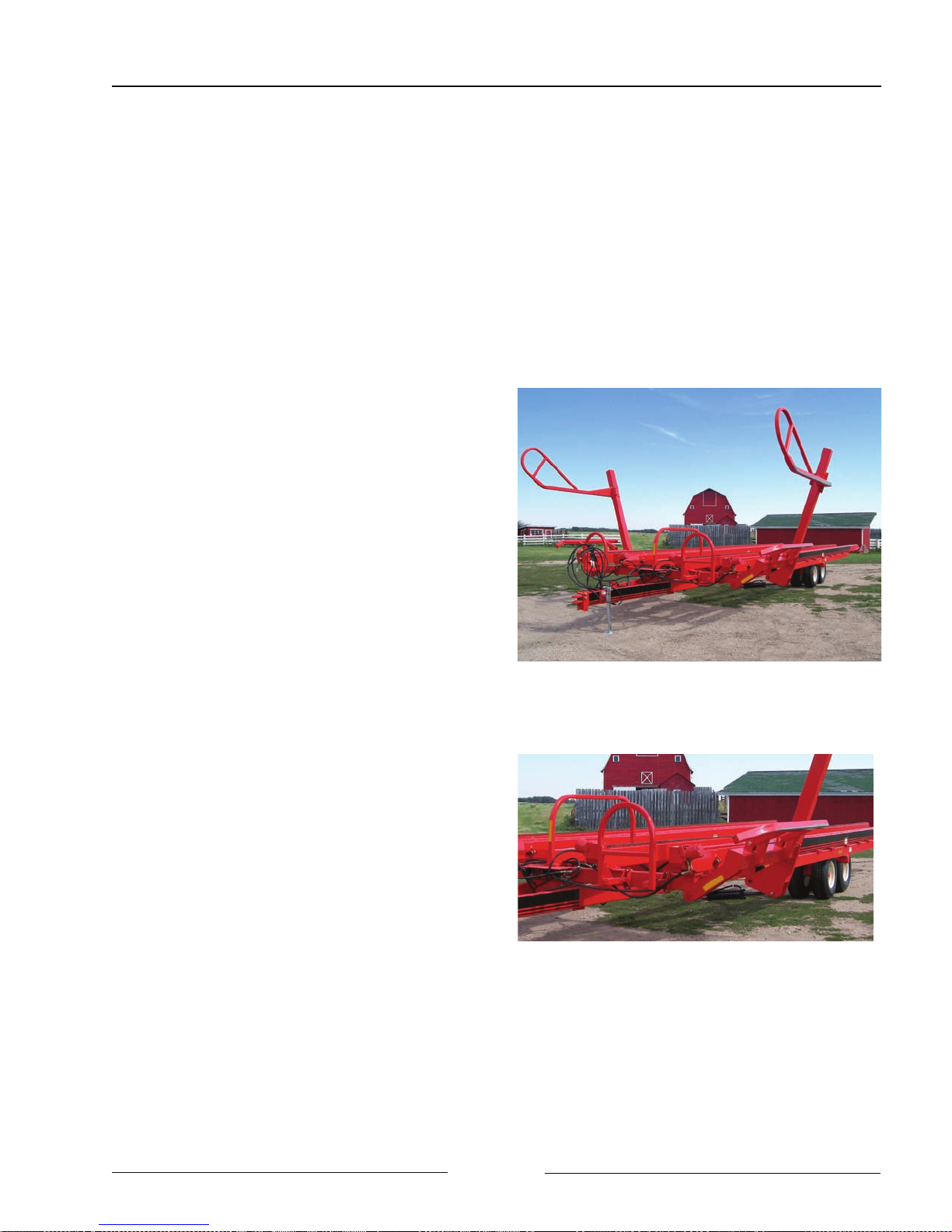
Bale Mover 1400
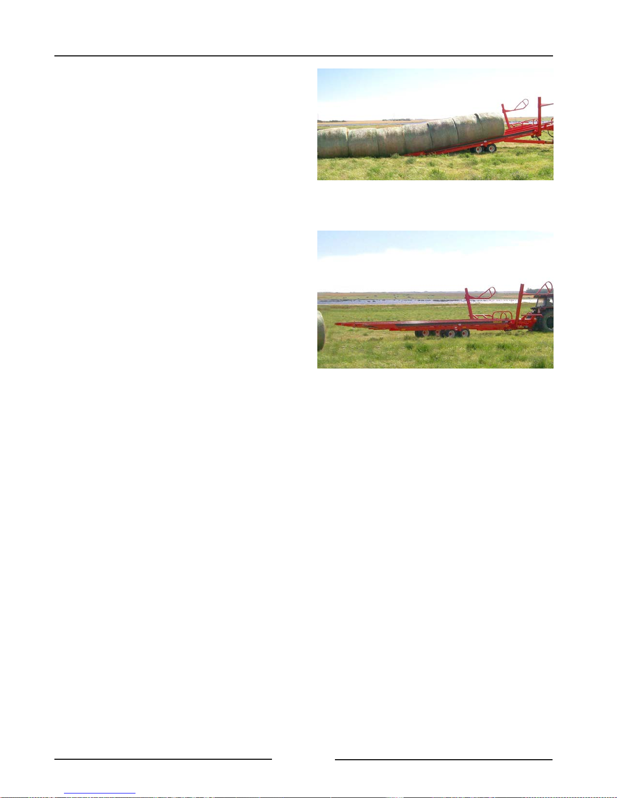
The Bale Mover has the ability to pickup
round bales from the left and right. It can
carry 7 bales in 2 rows. It easily unloads the
bales by tilting the bed, driving ahead while
the bale chains move the bales off the bed.
Bale Mover 1400
211010
The Bale Mover can also reload rows of
bales to be moved to another location. To
reload, tilt the bed and backup while the bale
chains move the bales onto the bed.
Unloading or Reloading Bales
211011
Page 8
Section 1 - Safety
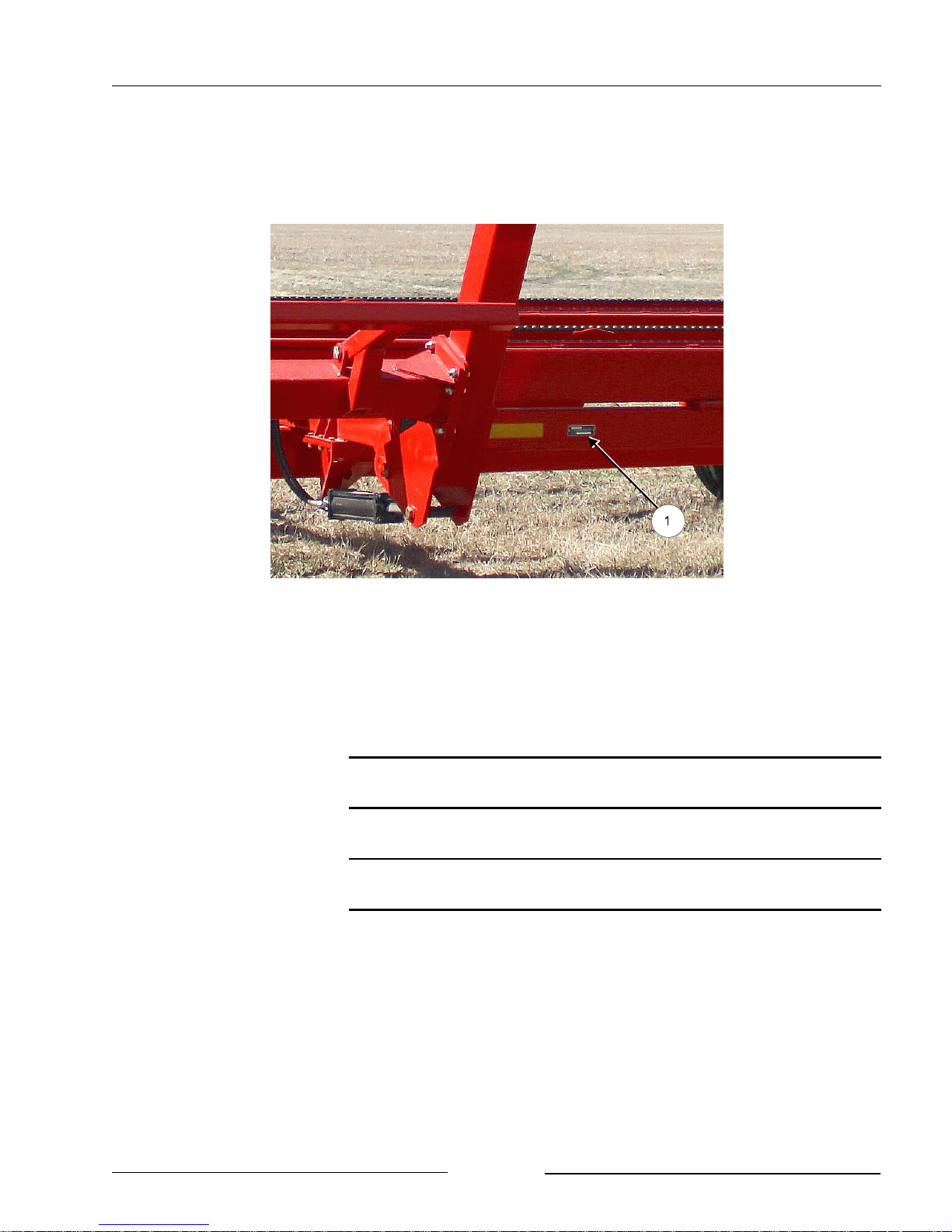
SERIAL NUMBER
Your serial number is found on the serial number plate (1) located on the left frame rail
behind the left bale lift arm.
Serial Number Plate Location
It is important to record the serial number for proof of ownership and for any service or
maintenance assistance.
218008C
Serial Number
Owner
Model
Date of Purchase
Be Trained Before Operating!
Page 1-1
Page 9

Section 1 - Safety
SAFETY SIGN-OFF FORM
Highline Manufacturing Ltd. follows the general Safety Standards specified by the American
Society of Agricultural Engineers (ASAE) and the Occupational Safety and Health Administration
(OSHA). Anyone who will be operating and/or maintaining the Highline Bale Mover should read
and clearly understand all Safety, Operating and Maintenance information presented in this
manual.
Do not operate or allow someone to operate this equipment until this information has been
reviewed. This information should be reviewed by all operator’s before the season start-up.
This sign-off sheet is provided for record keeping to indicate that the person working with the
equipment has read and understood the information in the Operator’s Manual and has been
instructed in the safe operation of the equipment.
Date Employee’s Signature Employer’s Signature
Page 1-2
Page 10
Section 1 - Safety
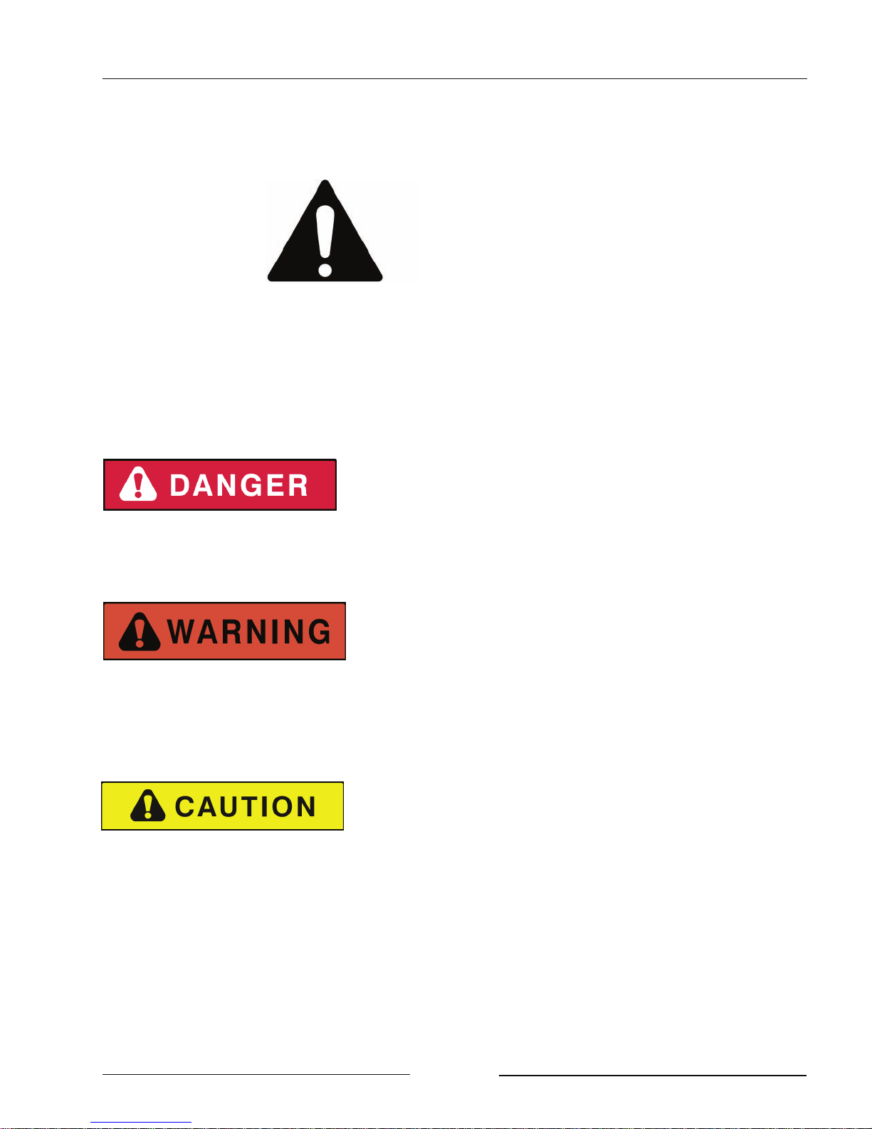
SAFETY ALERT SYMBOL
The Safety Alert Symbol means:
ATTENTION!
BECOME ALERT!
YOUR SAFETY IS INVOLVED!
The Safety Alert Symbol combined with a Signal Word alert to the presence of a hazard and the
degree of possible injury.
Indicates an imminently hazardous situation that, if not
avoided, WILL result in DEATH OR SERIOUS INJURY.
The color is Red with White lettering.
Indicates a potentially hazardous situation that, if not
avoided, COULD result in DEATH OR SERIOUS
INJURY, and includes hazards that are exposed when
guards are removed or unsafe practices. The color is
Orange with Black lettering.
Indicates a potentially hazardous situation that, if not
avoided, MAY result in MINOR INJURY. The color is
Yellow with Black lettering.
Page 1-3
Page 11

Section 1 - Safety
GENERAL SAFETY
1. Ensure that anyone who is going to operate, maintain or work near the Bale Mover is familiar
with the recommended operating, maintenance procedures and safety information contained
in this manual and follows all the safety precautions.
2. In addition to the design and configuration of the equipment, hazard control and accident
prevention are dependant upon the awareness, concern, prudence and proper training of
personnel involved in the operation, transport, maintenance and storage of the Bale Mover.
3. The Bale Mover shall not be operated without all the guards in place.
SAFETY DECALS
1. Keep decals and signs clean and legible at all times.
2. Replace decals and signs that are damaged, missing or have become illegible.
3. Replaced parts that displayed a decal should also display the current decal.
4. Decals are available from the Highline Parts Department.
5. Be familiar with the decals, the type of warning and the area or function(s) related to the
area(s) that requires your awareness.
Page 1-4
Page 12
Section 1 - Safety
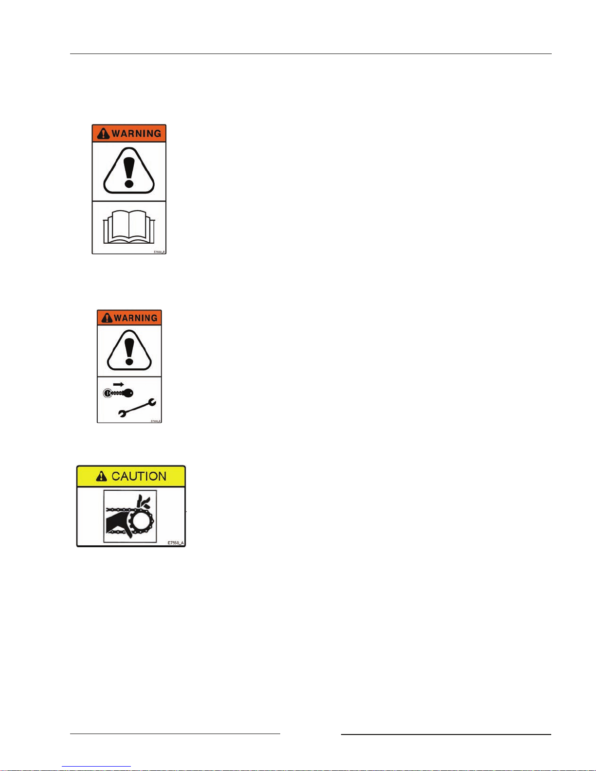
READ, UNDERSTAND, AND FOLLOW SAFETY INSTRUCTIONS
Read, understand and follow all instructions and safety messages
included in this manual and on decals attached to the machine.
Allow only responsible, properly instructed individuals to operate
and service the machine.
Failure to follow the instructions and safety messages in this
manual and on the decals attached to the machine could result in
serious injury or death.
Keep all safety and instruction decals in good condition. Replace
any missing or damaged decals.
STOP TRACTOR BEFORE GOING NEAR MACHINE
Always disengage power take off, shut off tractor, remove key, set
park brake and wait for all parts to stop turning before servicing.
DO NOT OPERATE WITH SHIELDS MISSING
Close and secure guards and shields before starting machine.
Keep hand, feet, hair and clothing away from moving parts.
Contact with moving chains or parts could cause serious injury or
death.
Page 1-5
Page 13
Section 1 - Safety
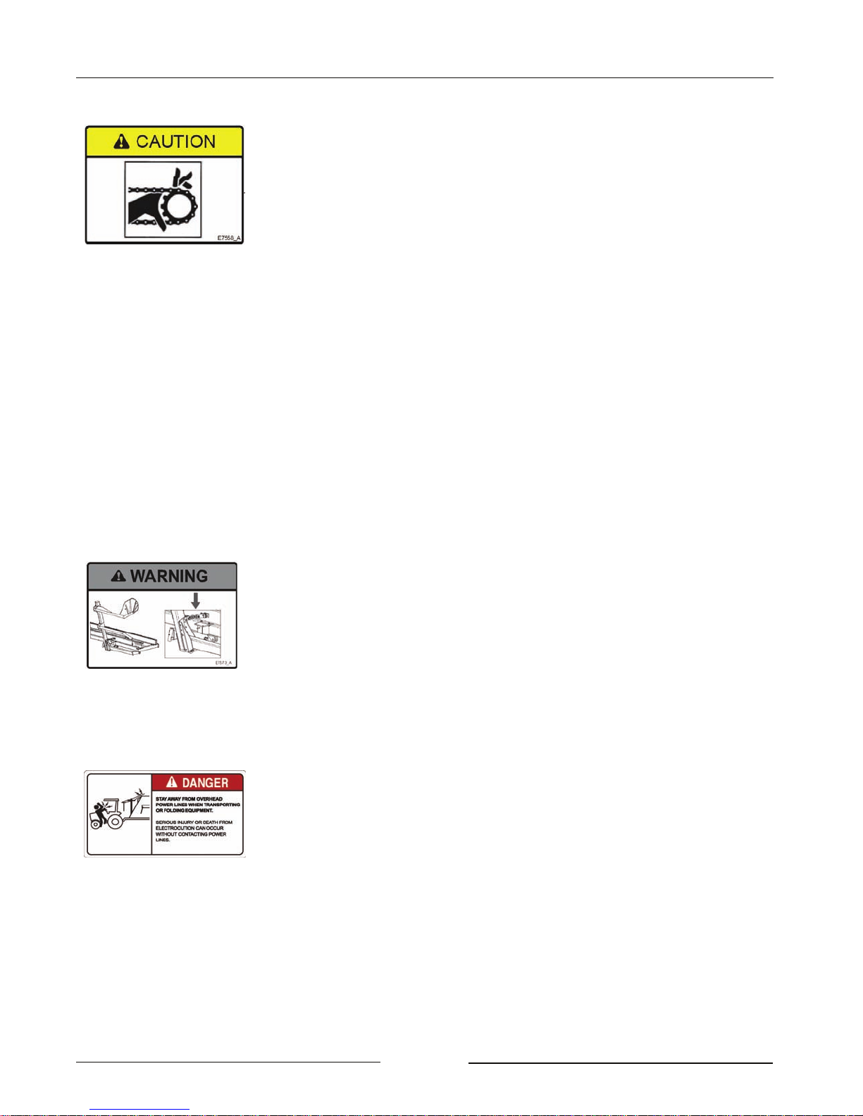
DO NOT CONTACT MOVING CHAIN
Contacting moving chain or parts could cause serious injury or death.
Never attempt to manually remove bales from rails while hydraulic
motors are moving the chain
.
Disconnect chain drive hydraulic motors before cleaning the Bale
Mover.
Always disengage power take off, shut off tractor, remove key, set
park brake and wait for all parts to stop turning before servicing.
KEEP PEOPLE BACK WHEN LOADING OR UNLOADING
BALES
Falling bales can cause serious injury or death.
Stand clear of Bale Mover when PTO is engaged.
Do not operate within 100 ft (30m) of any person.
STAND CLEAR OF BALE LIFT ARMS
Moving lift arms can cause serious injury or death.
Never stand under lift arms when lowering or raising.
Do not allow people near the lift arms when the being moved.
Lift arms must be fully retracted and locked in place before
servicing.
Install arm lock chains before transporting bale mover.
STAY AWAY FROM OVERHEAD POWER LINES
Stay away from power lines when transporting or folding
equipment.
Electrocution can occur without contacting power lines.
Page 1-6
Page 14
Section 1 - Safety
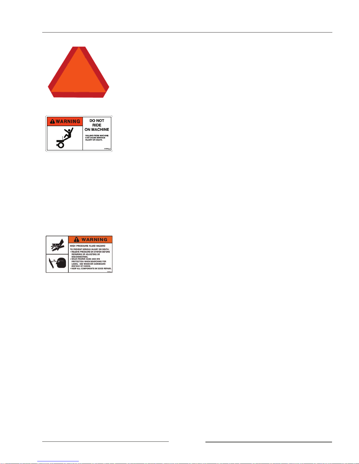
ENSURE SLOW MOVING VEHICLE SIGN IS IN PLACE
Ensure the Slow Moving Vehicle sign is in place, clean and easily
visible.
Ensure the reflectors are in place, clean and easily visible.
DO NOT RIDE ON MACHINE
Falling from the moving machine can cause serious injury or death.
Falling from the operating machine can cause being entangled
under the machine or being injured by the machine.
DO NOT OPERATE ON SIDE HILL
Tractor or bale mover roll over can cause serious injury or death.
Tractor must be equipped with Roll Over Protection System.
(ROPS)
Always wear seat belts when operating tractor.
USE PAPER OR CARDBOARD TO CHECK FOR HYDRAULIC
LEAKS
To prevent serious injury or death:
Relieve pressure on hydraulic system before repairing, adjusting or
disconnecting.
Wear proper hand and eye protection when searching for leaks.
Use wood or cardboard instead of hands.
Keep all components in good repair.
Fluid injected under the skin must be removed immediately by a
surgeon familiar with this type of injury.
Page 1-7
Page 15
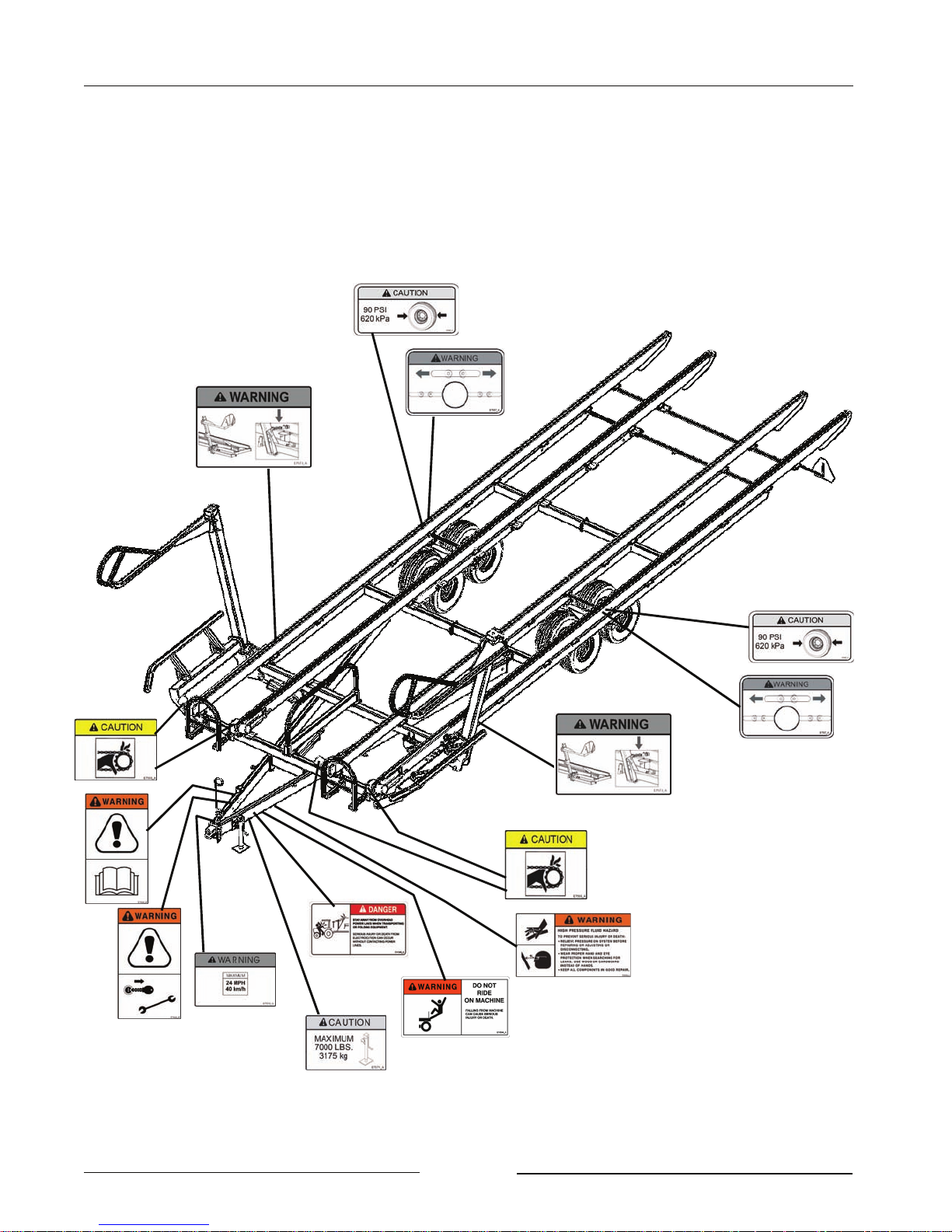
SAFETY DECAL LOCATIONS
Section 1 - Safety
211073
Page 1-8
Page 16
Section 2 - Transporting the Bale Mover
2.0 TRANSPORTING THE BALE MOVER
Only tow the Bale Mover behind a
properly sized and equipped
tractor or vehicle which exceeds
the weight of the loaded Bale
Mover by 50%.
Shut off the tractor engine before
attaching the bale mover or
hydraulics.
Do not allow children or other
people to ride on the tractor or
Bale Mover. Falling off can result
in serious injury or death.
1. Tractor Requirements
- Roll Over Protection System (ROPS)
- Working seatbelts
- 2 Spool Control Valves (SCV)
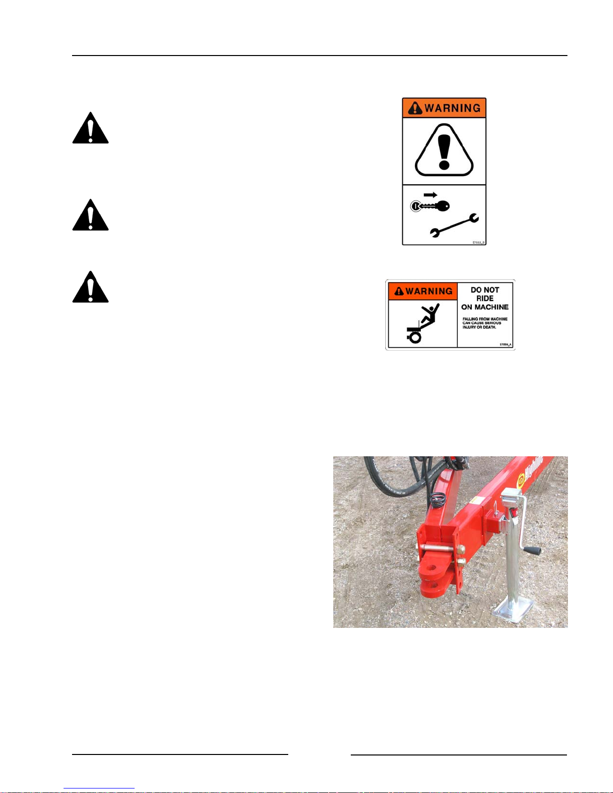
2. Adjust position of the tongue plate.
- Position the tongue plate so that the
bale mover is level when connected to
the tractor drawbar.
- Remove the bolts and move the
tongue plate. Fasten in place.
Adjust Position of the Tongue Plate
211071
Page 2-1
Page 17
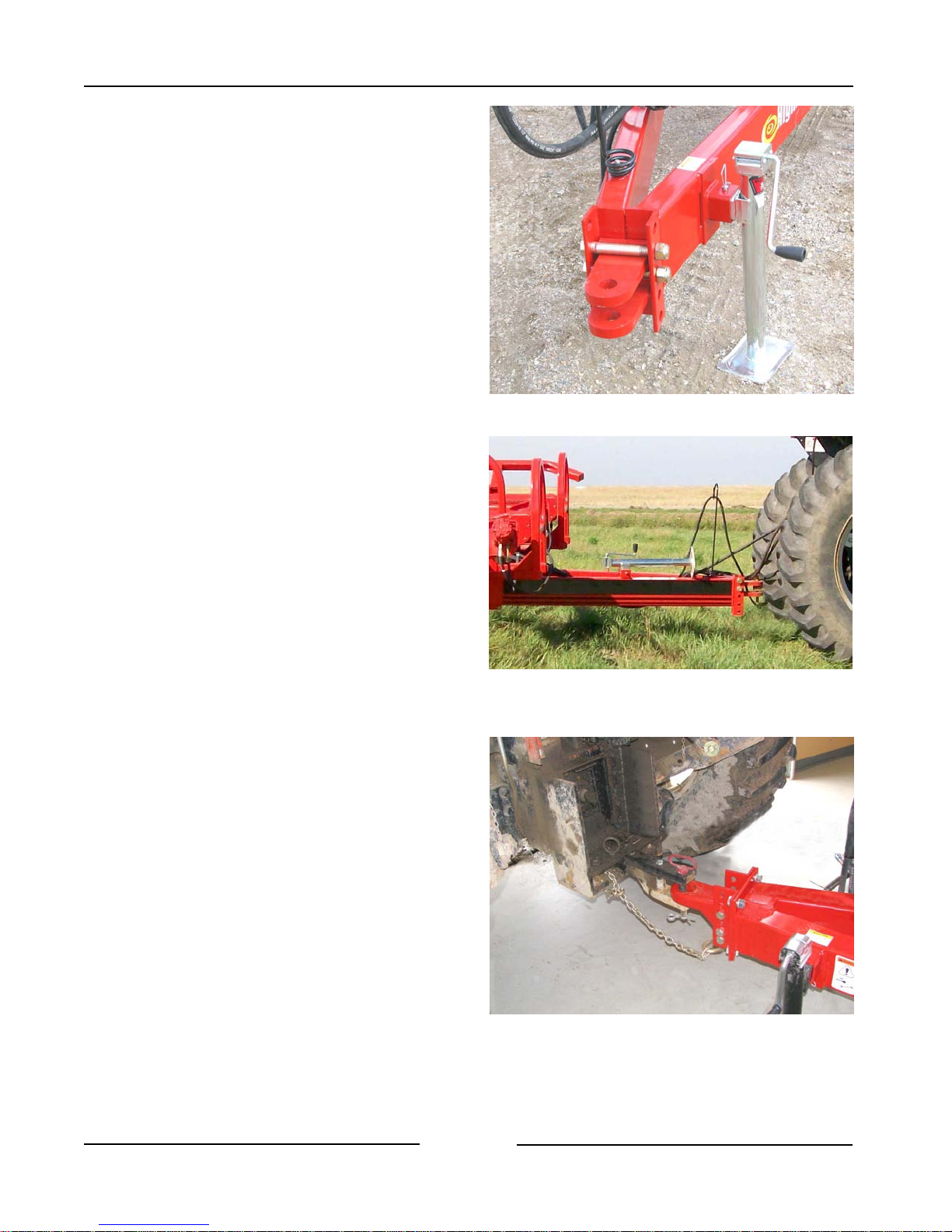
3. Lift the Hitch
- Lift the Hitch with the jack.
- Do not attempt to lift the hitch
without using the jack.
Section 2 - Transporting the Bale Mover
4. Connect the hitch to the tractor drawbar.
- Use at least a 1 1/4" (31.75 mm) pin.
5. Connect the safety chain to the tractor
and fasten securely.
Lift Hitch with the Jack
Connect The Hitch
211074
211072
6. Tractor Wheel Tread Width Settings
- When working on inclines or rough
ground, use the largest tractor wheel
width possible to maintain tractor
stability.
Page 2-2
Connect the Hitch and Safety Chain
215032
Page 18
Section 2 - Transporting the Bale Mover
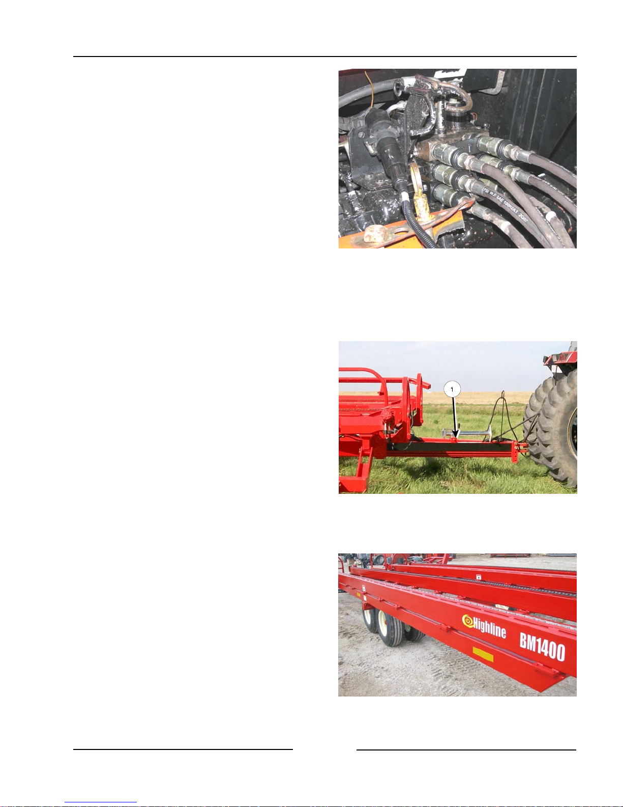
7. Attach Hydraulic Hoses
- Clean the end of the hoses and the
connection.
- Firmly push the hoses into the tractor
receptacle according to user
preference.
- Route the hoses so they do not
interfere with moving parts.
8. Connect the lighting cable to the electrical
connection on the tractor.
9. Route the Electric Control Cable
Attach Hydraulics and Lighting
108008
- Route the electric control cable into
the tractor cab.
- Ensure the cable does not interfere
with or contact moving parts.
10. Place the Hitch Jack in the Storage
Location.
- Remove all weight from the jack.
- Remove the locking pin holding the
jack onto the hitch.
- Place the jack to the storage position
(1).
- Fasten the jack in place with the lock
pin.
11. Lower the Bale Mover bed.
Jack in the Storage Location
211072
Page 2-3
Lower the Bed
211034
Page 19
Section 2 - Transporting the Bale Mover
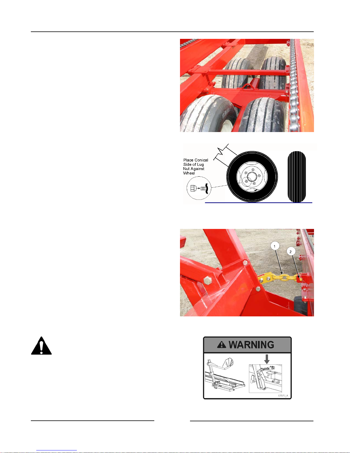
12. Check the condition of all the tires.
- Ensure that the lug nuts have the
cone side of the lug nut against the
wheel rim.
- Torque the lug nuts to 170 lbf (230
Nm).
- Fill the tires to 90 psi (620 Kpa).
13. Raise both bale lift arms.
14. Install the lift arms transport lock
chains (1) on both arms.
- Install the chain pins (2) and clip into
place with the spring pins.
Always use fork transport chains
when transporting Bale Mover on
public road ways. Forks may
descend rapidly if hydraulic
pressure is lost to a lift cylinder.
Tires
Install Transport Lock Chains
107094CC
211036C
Page 2-4
Page 20
Section 2 - Transporting the Bale Mover
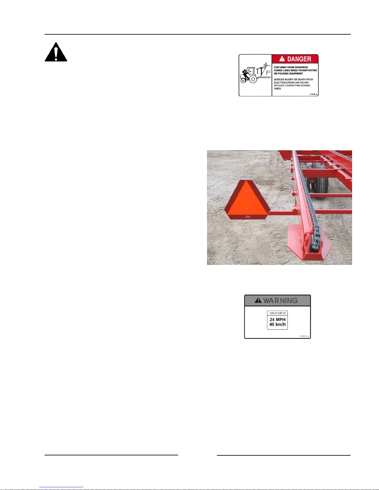
Stay away from overhead power
lines. Electrocution can occur
without contacting power lines
15. Ensure that the Slow Moving Vehicle
(SMV) sign (1) is clean and visible.
16. Transport Speed
- Do not exceed 24 mph (40 km/h).
Ensure SMV is Clean and Visible
211035
Page 2-5
Page 21

Section 2 - Transporting the Bale Mover
This Page Left Blank
Page 2-6
Page 22
Section 3 - Bale Mover Preparation
3.0 BALE MOVER PREPARATION
1. Park the tractor and Bale Mover on level
ground.
- Engage the tractor parking brake.
2. Ensure that all decals are clean and in
place.
3. Ensure that the Slow Moving Vehicle
(SMV) sign is clean and visible.
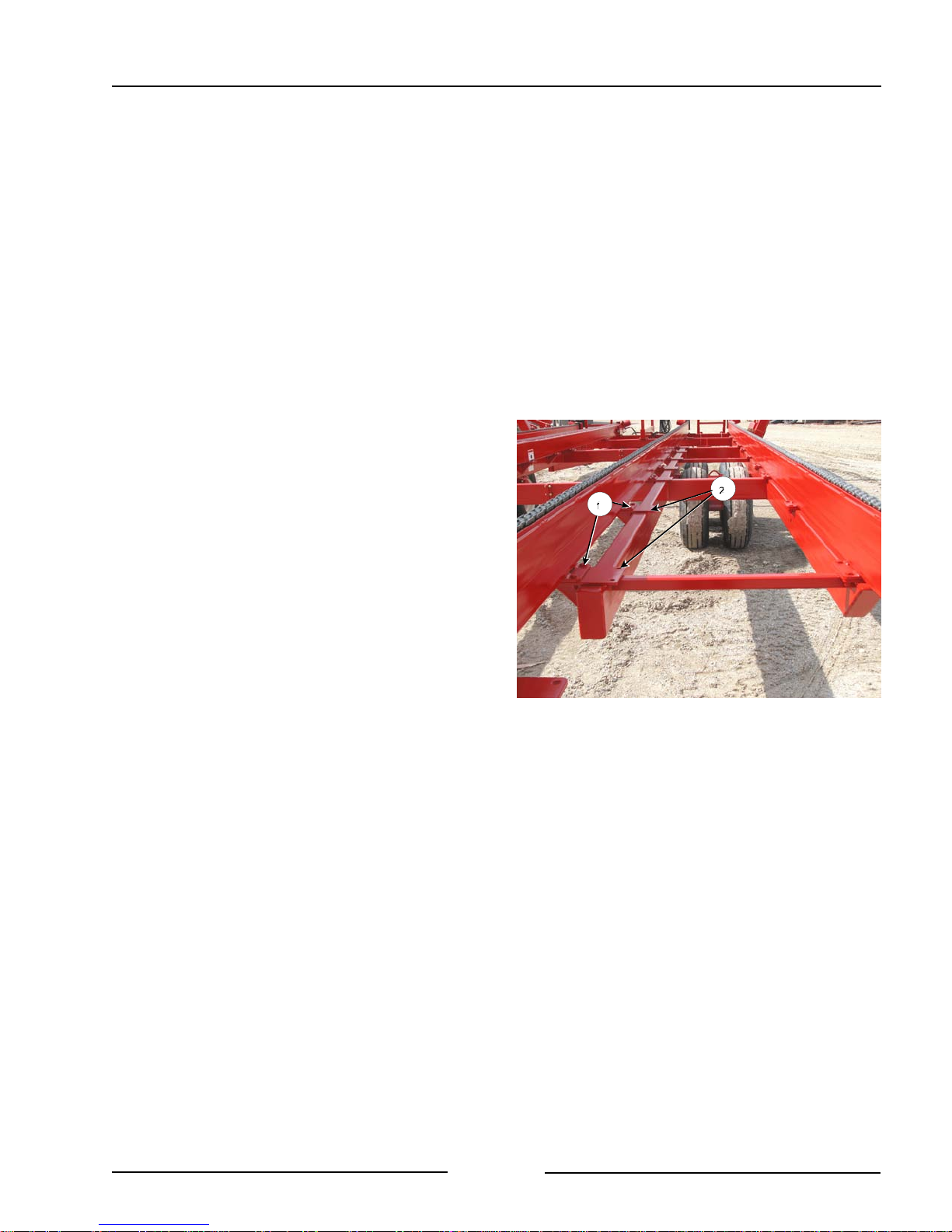
4. Adjust the bed chain rails for the size of
bale.
- The inside rails can be moved for the
size of bale being handled.
- Remove the bolts (1) from the rail
mounts plates along the length of the
rail.
- Slide the rail to the alternate mount
position (2) to suit the size of bale
being handled.
- Fasten the mount plates with the bolts
and nuts.
Adjust Rails for Size of Bale
211020
Page 3-1
Page 23
Section 3 - Bale Mover Preparation
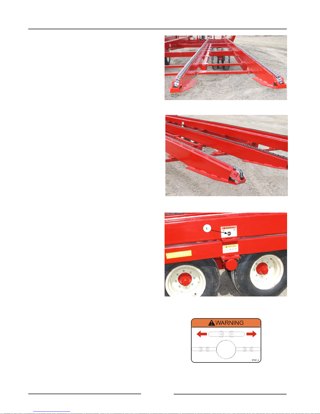
5. Check the Condition of the Bale Chains
- Clean debris and material buildup
from the chain area and the chain
channels.
- Check that no wire or other materials
are wrapped in the chain.
- Check that the chain is secure around
the end roller.
Check Condition of the Bale Chains
211037
- Check the tension on all the chains.
- The chain can be seen in the sight
hole (1) that is in the side of the
rail.
- The chain should be in line with
the image of the chain that is on
the decal at the sight hole.
- Adjust as necessary. See “Chain
Adjustment Procedure” in the
Maintenance Section.
Check That The Chain Is On The End Roller
Check Tension of All the Chains
211038
211061
Page 3-2
Chain Tension
E7567_A
Page 24
Section 3 - Bale Mover Preparation
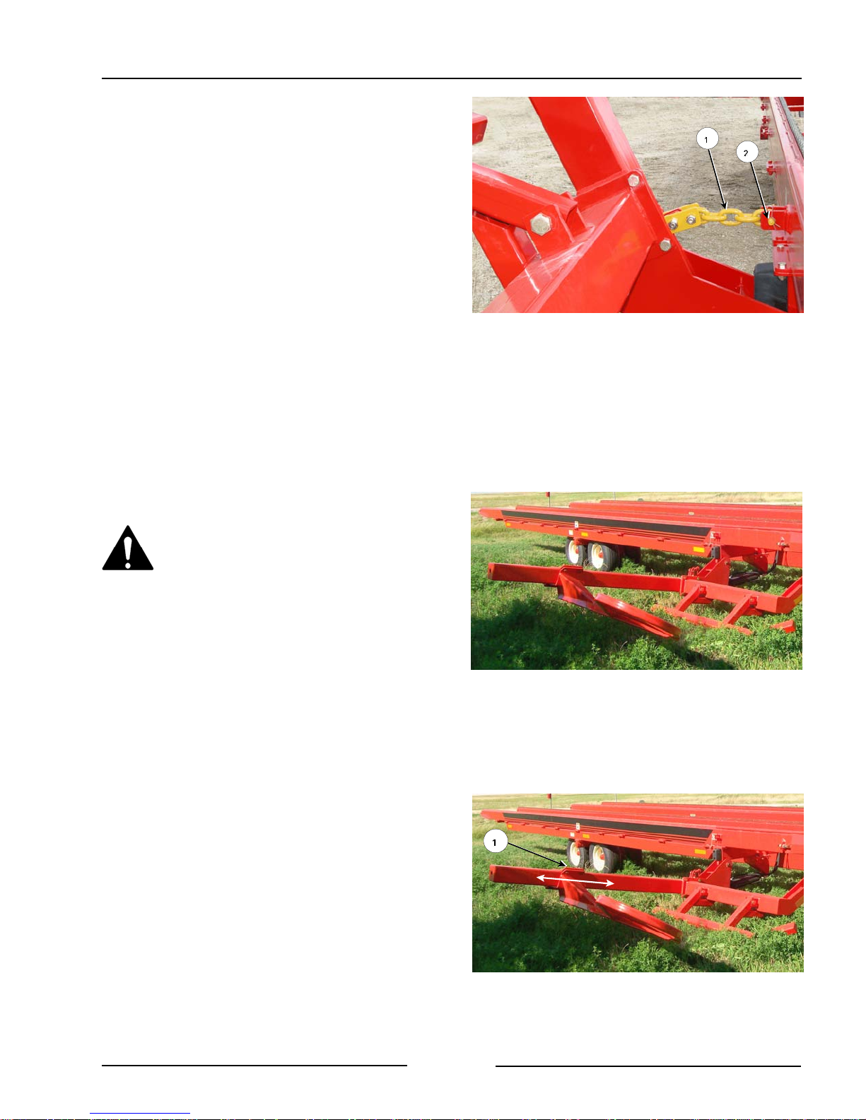
6. Remove the lift arm transport chains on
both arms.
- Raise arms to remove tension on the
transport chain.
Note: Do not lower the forks when transport
chains are in position or damage to
the machine will occur.
- Remove the clip pin (2) and remove
the chain pin (1).
- Place the chain pin (1) back into the
tabs and lock in place with the clip pin
(2).
7. Lower the bale lift arms.
Stand Clear of Bale Lift Arms
- Moving lift arms can cause serious
injury or death.
- Never stand under lift arms when
lowering or raising.
- Do not allow people near the lift
arms when the being moved.
Remove Transport Lock Chains
211036C
Note: Do not lower the forks when transport
chains are in position or damage to
the machine will occur.
8. Set the Width of the Bale Lift Arms
- Loosen the bolts on the arm clamp
(1).
- Slide the arm to the suit the size of the
bale.
- Tighten the bolts on the holding clamp
to fasten the lift arm.
Page 3-3
Slide Clamp for Bale Width
211041C
Page 25
Section 3 - Bale Mover Preparation
9. Check that the bale lift arms operate
freely when lifting.
Stand Clear of Bale Lift Arms
- Moving lift arms can cause serious
injury or death.
- Never stand under lift arms when
lowering or raising.
- Do not allow people near the lift
arms when the being moved.
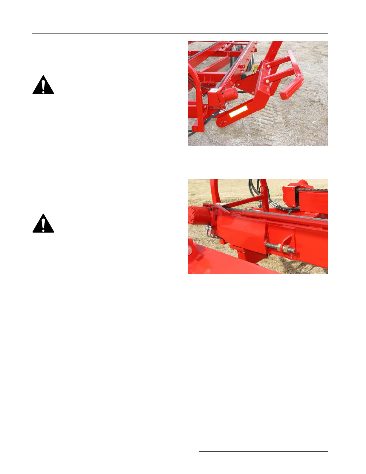
10. Check that the chain guards on the
hydraulic motors are in place and in
good condition.
Check that Lift Arm Operates Freely
211044
The Bale Mover shall not be
operated without all the chain
guards in place and in good
condition.
- Replace missing or broken guards
immediately.
Ensure Motor Chain Guards Are In Place
211046
Page 3-4
Page 26
Section 3 - Bale Mover Preparation
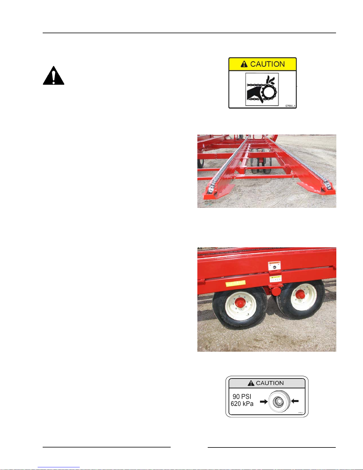
11. Engage the bale chains motors to
ensure the chains operate smoothly.
Contacting moving chain or parts
could cause serious injury or
death.
12. Check the condition of the tires.
- Fill to an air pressure of 90 psi (620
kPa).
- Inspect the wheels and tires for
damage or foreign objects. Repair or
replace as necessary.
Check that Bale Chains Operate Smoothly
Check the Condition of the Tires
211037
211043
Page 3-5
Page 27
Section 3 - Bale Mover Preparation
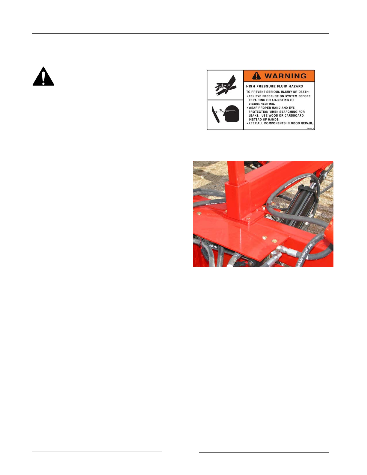
13. Inspect All the Hydraulic Motors,
Cylinders and Hoses
Use a piece of cardboard or
heavy paper to check for leaks.
Do not use your hand. Wear
proper hand and eye protection
when searching for leaks.
Relieve pressure on hydraulic
system before repairing, adjusting
or disconnecting.
Note: If fluid is injected under the skin, it
must be removed immediately by a
surgeon familiar with this type of
injury.
- Visually inspect all the hydraulic hoses
and fittings.
- See Section 5 "Maintaining the
Bale Mover" for conditions
indicating that replacement is
needed.
- Ensure the proper size cylinder pins
are in place and secured.
Check All Hydraulic Connections
211045
Page 3-6
Page 28
Section 3 - Bale Mover Preparation
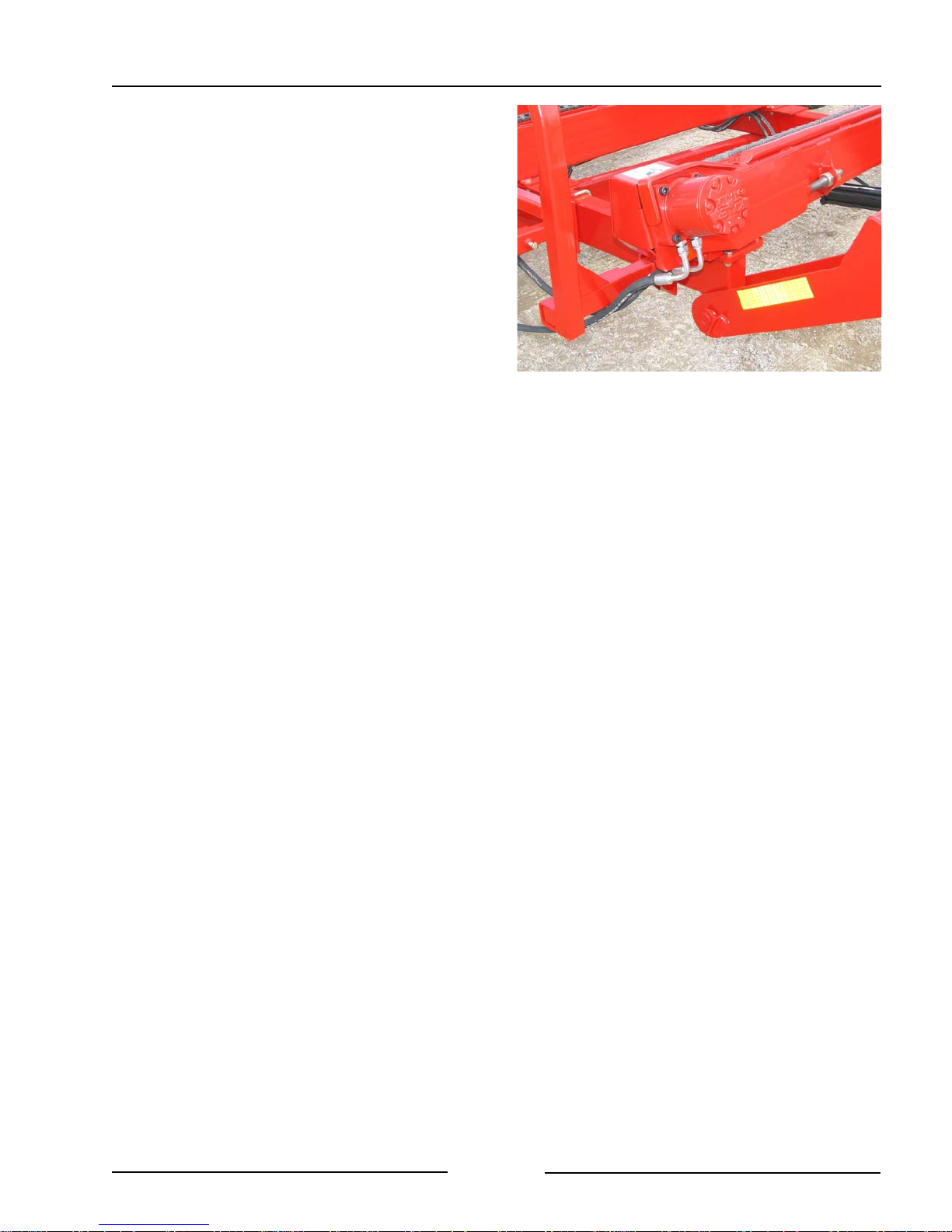
14. Check the condition of the hydraulic
motors and the connections.
15. Lubricate all grease fittings. See the
Maintenance Section.
16. Ensure all fasteners are tightened.
Check the Motor and Connections
211070
Page 3-7
Page 29

Section 3 - Bale Mover Preparation
This Page Left Blank
Page 3-8
Page 30
Section 4 - Operating the Bale Mover
4.0 OPERATING THE BALE MOVER
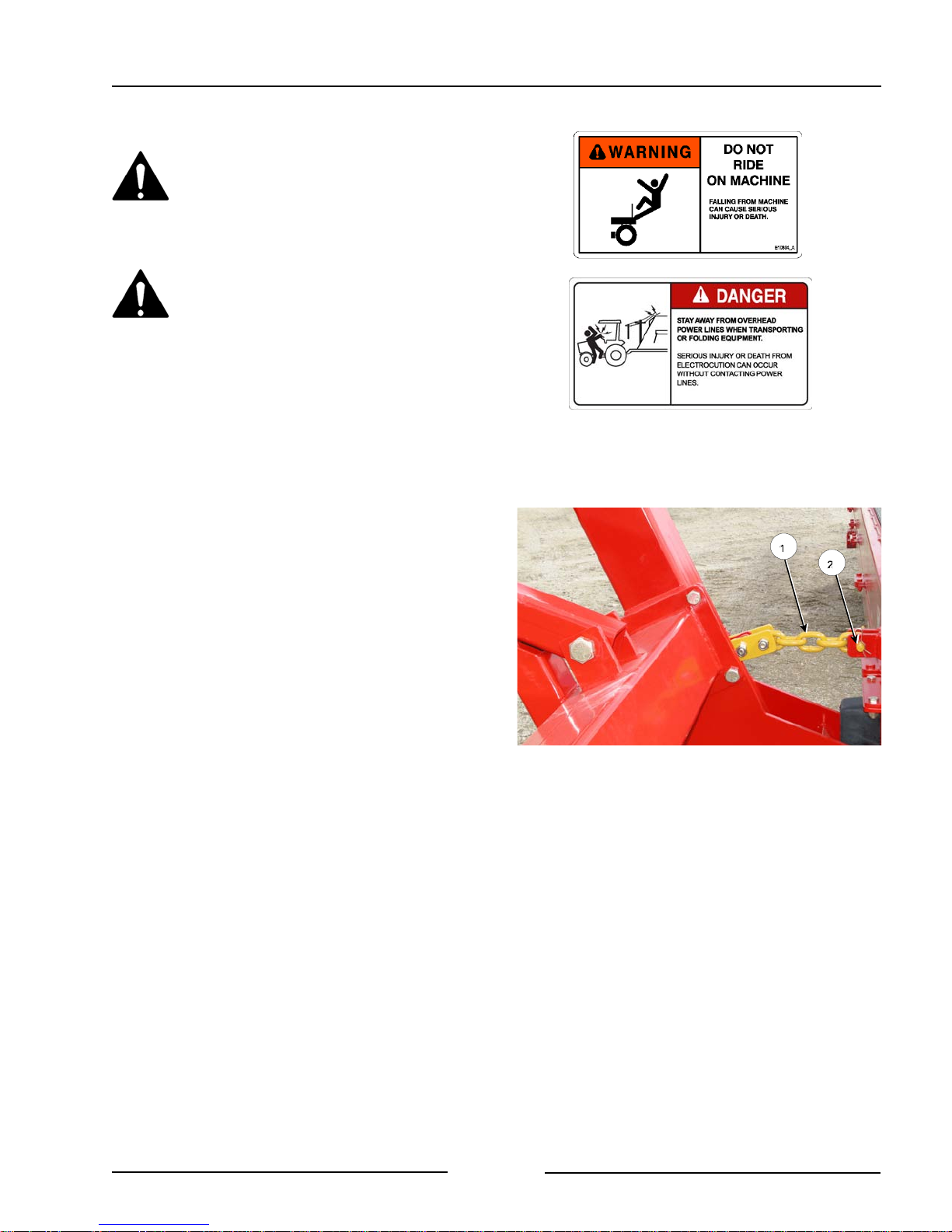
Do Not Allow Anyone to Ride on
the Bale Mover.
- Falling from the machine can
cause injury
Stay clear of overhead power
lines. Electrocution can occur
without contacting the power
lines.
1. Park on Level Ground
2. Remove the lift arm transport chains on
both arms.
Note: Do not lower the lift arm when
transport chains are in position or
damage to the machine will occur.
- Raise lift arms to remove tension on
the transport chain.
- Remove the clip pin (2) and remove
the chain pin (1).
- Place the chain pin (1) back into the
tabs and lock in place with the clip pin
(2).
Remove Arm Transport Chains
201118C
Page 4-1
Page 31
Section 4 - Operating the Bale Mover
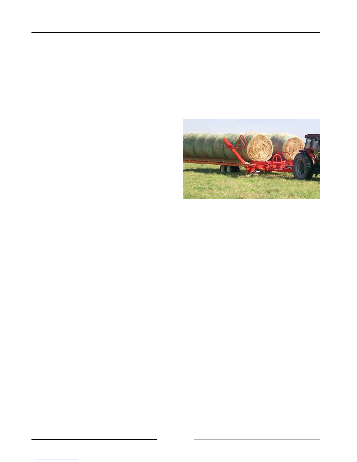
3. Drive the Bale Mover into the field area.
4. The Bale Mover should be operated at
field speeds of 3 - 4 mph (4 - 6 km/h).
- It is not required to stop to pick up a
bale.
5. Load the Bale Mover on both the left and
right sides as evenly as possible.
- This will ensure maximum stability for
the machine when operating and on
uneven terrain.
Page 4-2
Page 32
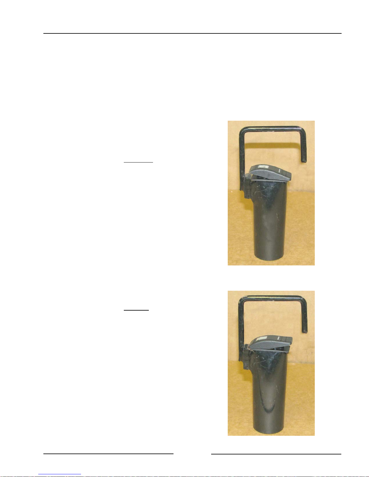
Section 4 - Operating the Bale Mover
LOADING BALES IN THE FIELD
Tractor Cab Controller
1. In the loading modes, the Control Switch
in the tractor cab enables the hydraulic
remotes to control the bale lift arms and
the bale roller chains.
- Hang the switch in a convenient
location in the tractor cab. Use the top
hook to secure it.
2. Loading bales on the right side
- Move the rocker switch to the right
position.
- One tractor remote will be used to
lift the bales into position onto the
right side of the deck.
- The other tractor remote will be
used to push the bale back on the
right deck once it is in position.
3. Loading bales on the left side
- Move the rocker switch to the left
position.
- One tractor remote will be used to
lift the bales into position onto the
left side of the deck.
- The other tractor remote will be
used to push the bale back on the
left deck once it is in position.
Right Side Loading
Left Side Loading
211052
211053
Page 4-3
Page 33
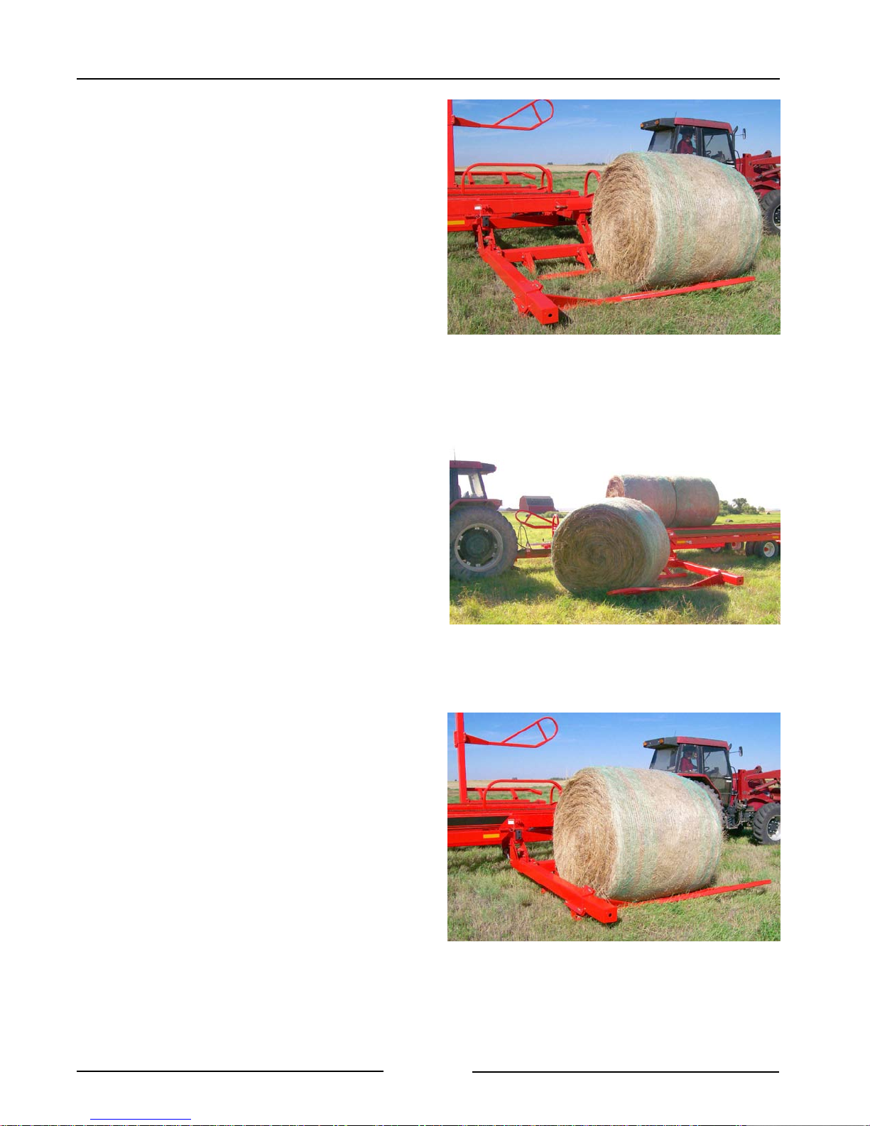
Section 4 - Operating the Bale Mover
4. Drive up to the bale and position the lift
arm forks so that it can lift the bale.
- It is not required to stop to pick up a
bale.
- Continue driving forward.
5. The lift arm can rotate a bale somewhat
to align it into the lift arm.
6. Drive forward until the lift arm forks are
fully under the bale.
Drive Up to Bale with Arm Lowered
Bale Can Be Rotated Some by the Lift Arm
211013
211016
Page 4-4
Drive Forward Until Fork Under Bale
211029
Page 34
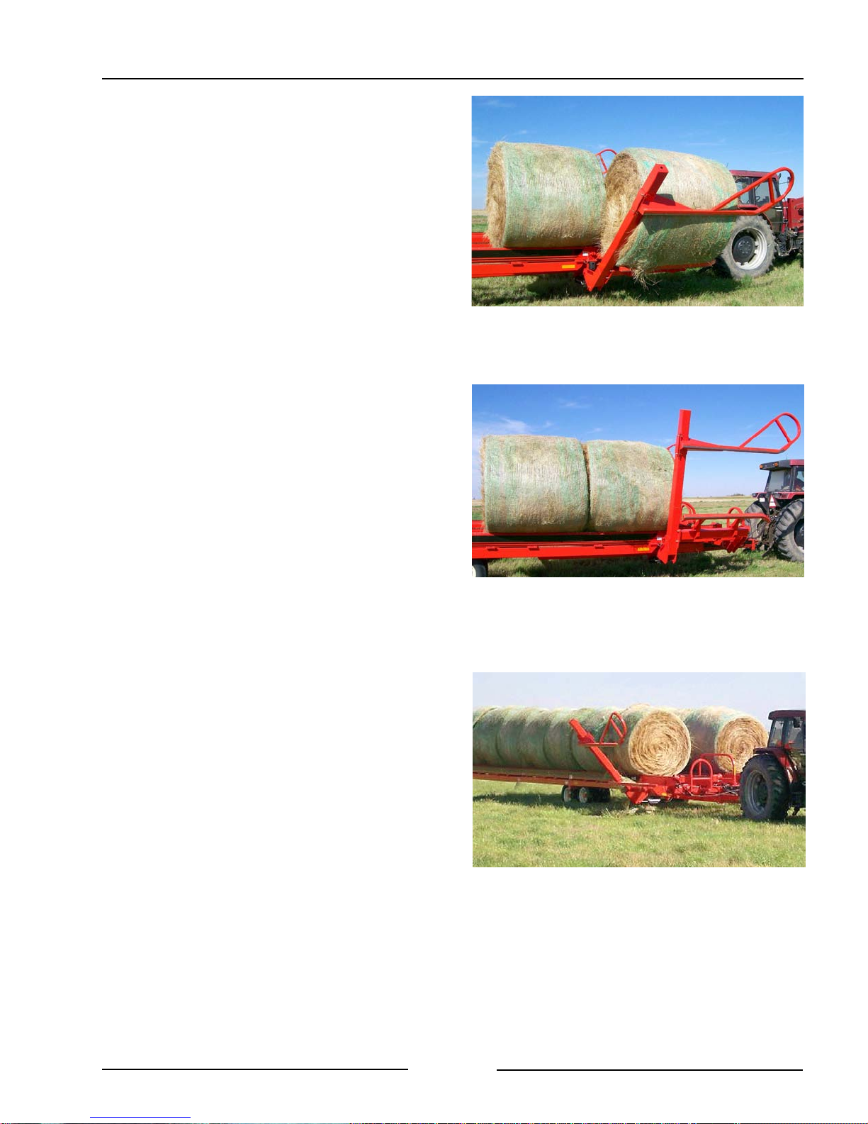
Section 4 - Operating the Bale Mover
7. Activate the hydraulic remote to lift the
arm and place the bale onto the bale
chains.
8. Activate the bale chain to move the bales
back.
- This will allow room for another bale to
be loaded.
Lift Bale Onto the Bed
Move Bales Back On Chain Rails
211014
211032
9. Up to 7 bales can be loaded on both the
right and left sides of the Bale Mover.
Page 4-5
Load Bales onto Right and Left
211010
Page 35
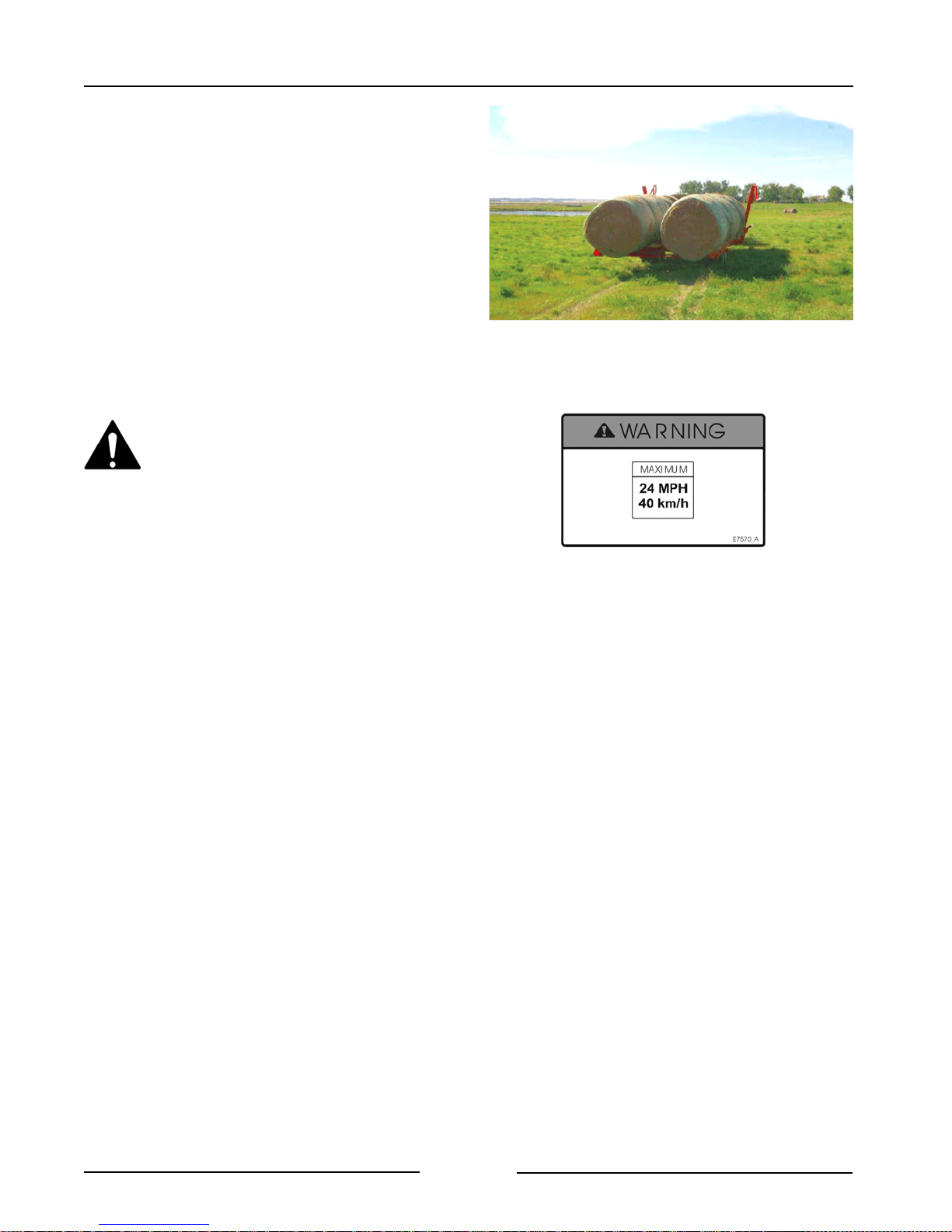
Section 4 - Operating the Bale Mover
10. Drive to the bale storage site.
- Adjust ground speed to suit the terrain
to maintain stability of the load.
Do not transport the loaded Bale
Mover faster than 24 mph/40
km/h.
11. If traveling on roadways:
- Ensure the bales are securely
strapped to the mover.
- Ensure the clearance lights and
SMV are pivoted out and visible.
Drive To The Bale Storage Site
211033
- Ensure the lights are operating.
- Consult the local road regulations
regarding securing the load and
road travel. Follow all the
applicable regulations.
Page 4-6
Page 36

Section 4 - Operating the Bale Mover
UNLOADING BALES
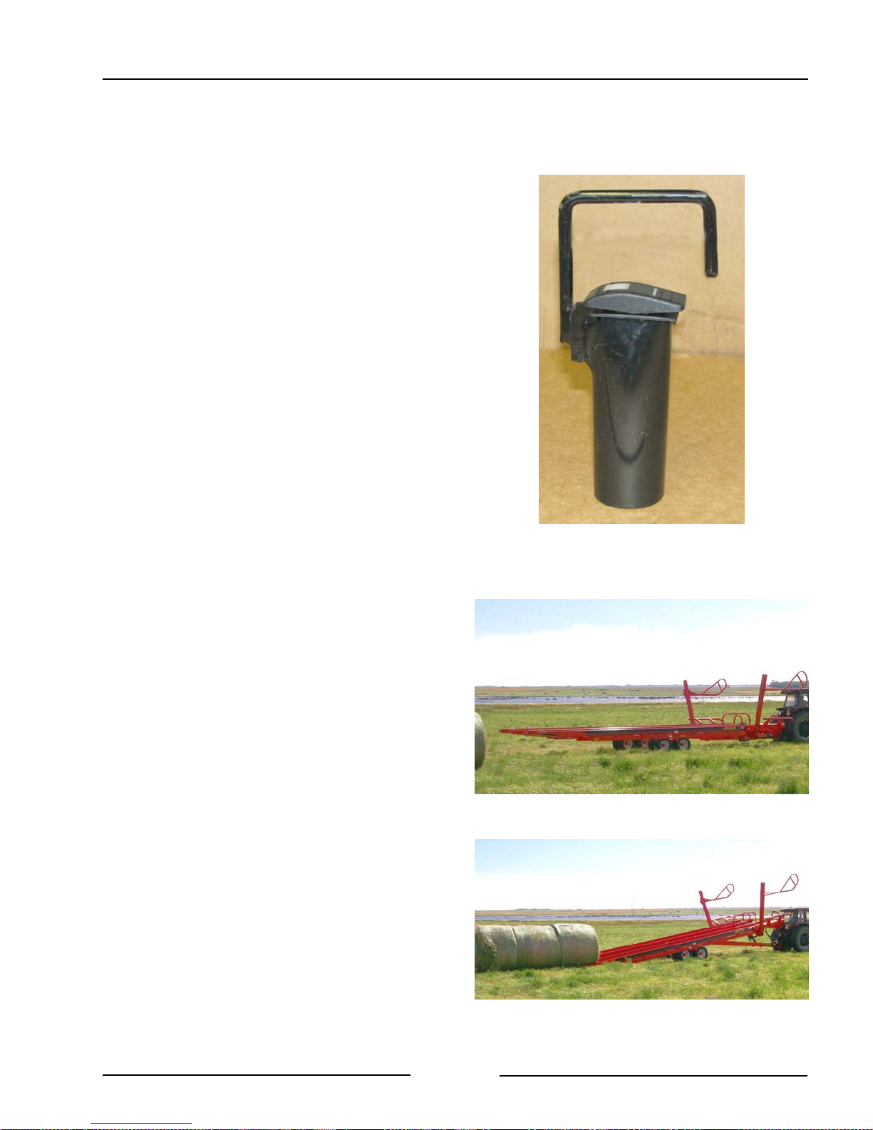
1. The Control Switch in the tractor cab
enables the hydraulic remotes to control
the bed tilt and the bale roller chains.
- Center the electric rocker switch.
- Use one tractor remote to tilt the
bed to the unload position.
- Use the other tractor remote to
operate the roller chains to push
the bales back and slide them off
of the deck.
2. Position the Bale Mover to unload the
bales in the storage location.
3. Tilt the bed to the fully raised position.
Bed Tilt and Unload
Position in the Storage Location
211054
211055
Page 4-7
Tilt Bed to Fully Raised Position
211050
Page 37
Section 4 - Operating the Bale Mover
4. Engage the bale roller chains to move the
bales toward the back of the Bale Mover
and off the bed.
5. Slowly drive forward as bales are
unloading.
6. When bales are unloaded and clear,
lower the bed completely into the
operating position.
Engage Chains and Drive Ahead
Lower the Bed
211056
211058
Page 4-8
Page 38
Section 4 - Operating the Bale Mover
RELOADING BALES
Bales can be reloaded from the bale row
onto the Bale Mover.
1. The Control Switch in the tractor cab
enables the hydraulic remotes to control
the bed tilt and the bale roller chains.
- Center the electric rocker switch.
- Use one tractor remote to tilt the
bed to the reload position.
- Use the other tractor remote to
operate the roller chains to push
the bales forward onto the deck.
2. Position the Bale Mover to reload the
bales from the storage location.
3. Tilt the bed to the fully raised position.
Tilt and Reload Position
Position to Reload Bales
211054
211058
Page 4-9
Tilt Bed to Fully Raised Position
211059
Page 39
Section 4 - Operating the Bale Mover
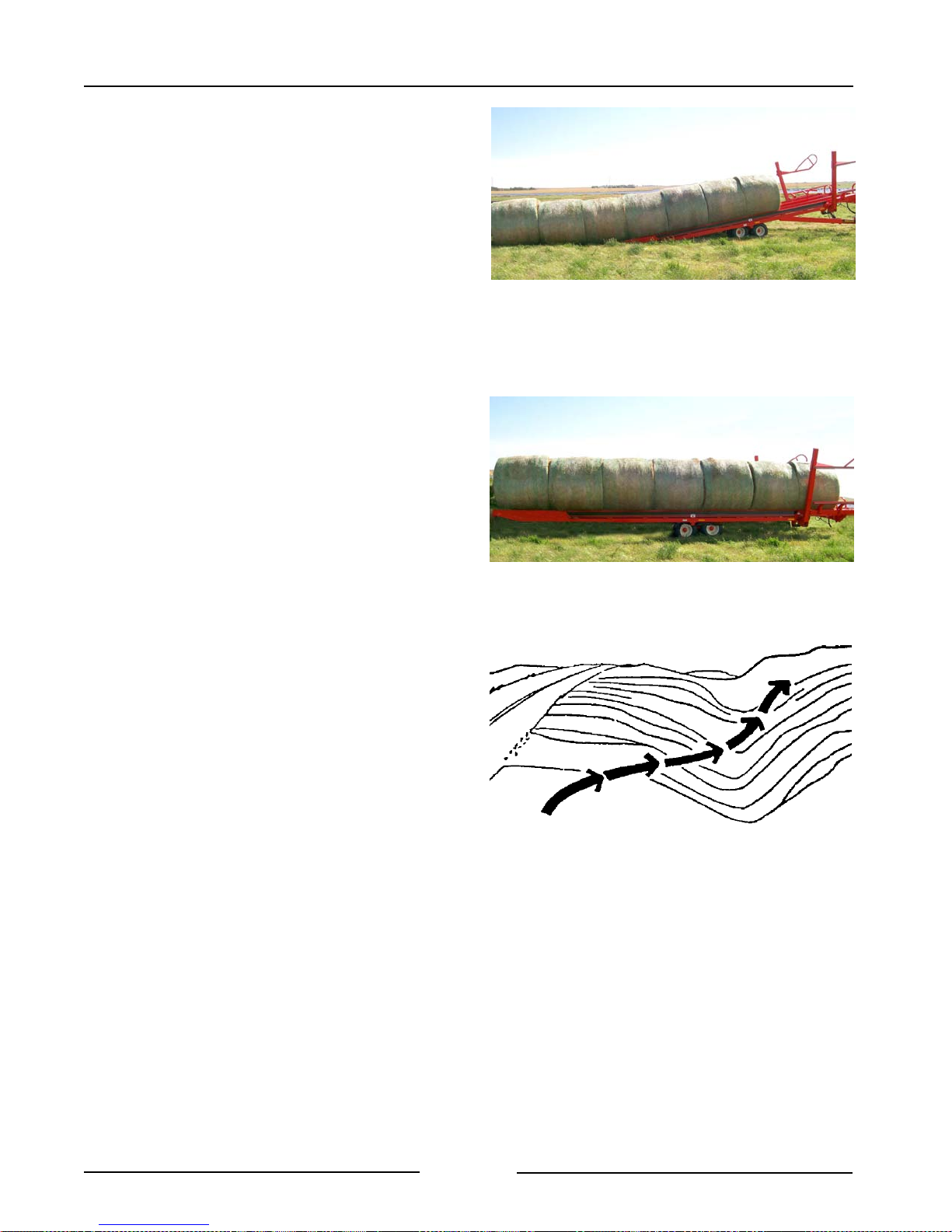
4. Engage the bale roller chains to move the
bales forward and onto the Bale Mover
bed.
5. Slowly back up towards the bales as they
are reloading.
6. When bales are reloaded, lower the bed
completely into the operating position.
7. Crossing Ditches and Steep Inclines
- Cross ditches or inclines at about a
30° approach angle.
Engage Chains and Back Up
Lower Bed When Done Reloading
211056
211060
Cross Ditch at 30° Angle
Page 4-10
107072
Page 40
Section 5 - Maintaining the Bale Mover
5.0 MAINTAINING THE BALE MOVER
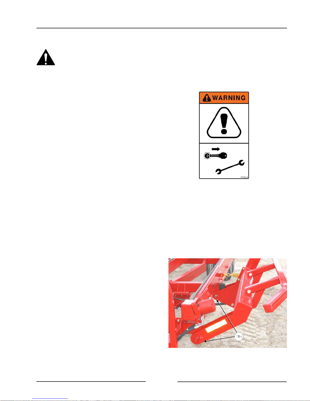
Shutdown Procedure
For your safety and the safety of
others, this procedure must be
followed before dismounting from
the tractor for repairing, servicing,
cleaning, or lubricating the Bale
Mover.
Step 1: Reduce the engine speed to idle.
Step 2: Fully lower left & right fork lifts.
Step 3: Disengage hydraulic motors.
Step 4: Set the tractor park brake.
Step 5: Shut off tractor engine and remove
the key.
Step 6: Relieve hydraulic pressure and
disconnect hydraulic hoses.
Lubrication
Lubricate all grease fittings with a quality
lithium complex, extreme pressure NLGI
Grade 2 grease.
Every 10 Hours
! Side Lift Arms- Lubricate 2 points on each
side lift arm every 8 hours.
- 1 point at the front pivot.
- 1 point at the rear pivot.
Grease Both Side Lift Arms
211062C
Page 5-1
Page 41
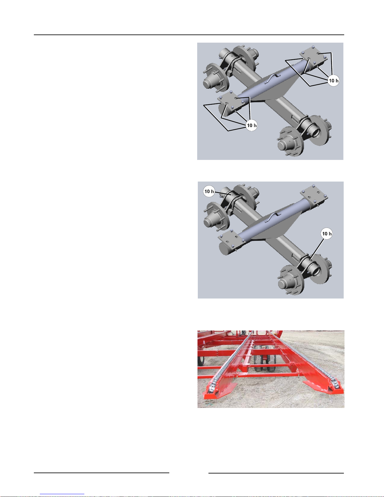
Section 5 - Maintaining the Bale Mover
! Lubricate 8 points on each axle shaft
- Lubricate 4 points on each end of the axle
pivot shafts.
- 2 points through the holes in the rail
mount plate.
- 2 points on the front and back of the
shaft ring.
- Lubricate left and right side pivot
shafts.
! Lubricate 2 points on the tandem axle
pivots
- 1 point on each tandem pivot.
- Lubricate left and right side tandems.
! Lubricate the chains with a quality chain
oil.
Grease Each End of the Axle Pivot Shaft
Grease Each Tandem Axle Pivot
211068C
211068C2
Page 5-2
Lubricate the Bale Chains
211037
Page 42
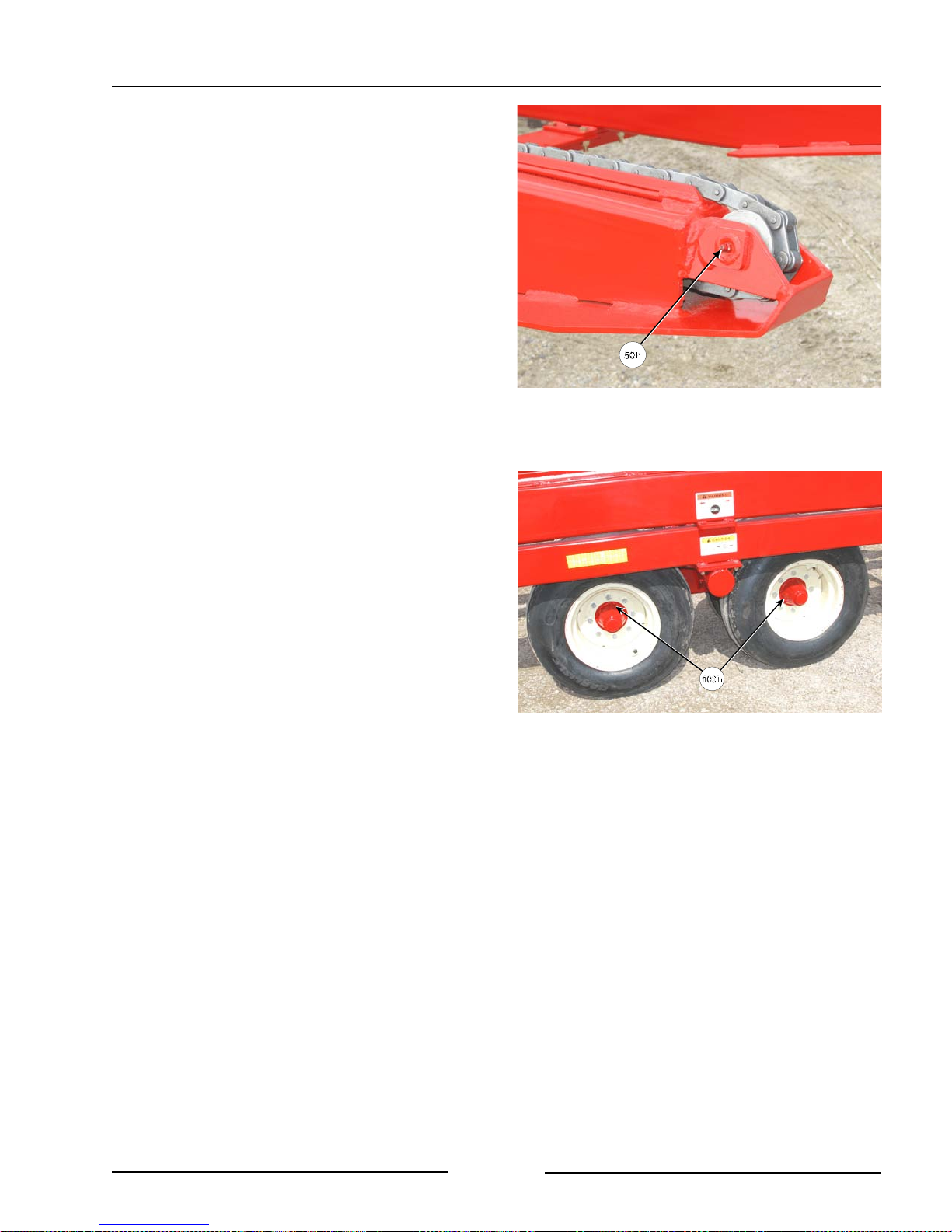
Section 5 - Maintaining the Bale Mover
Every 50 Hours
! Lubricate 1 point on each rear chain
roller.
- Lubricate the 4 chain roller.
Every 100 Hours
! Lubricate all the hubs on the spindles.
Visually Inspect Hydraulic Hoses/Fittings
Shut down the machine and replace the
hydraulic hose assembly if any of the
following conditions exist:
Grease Rear Chain Roller
Grease Hubs on all Spindles
211065C
211064C
- Fitting slippage on hose.
- Damaged, cracked, cut or abraded
cover (any reinforcement exposed).
- Hard, stiff, heat cracked or charred
hose.
- Cracked, damaged or badly corroded
fittings.
- Leaks at fitting or in hose.
- Kinked, crushed, flattened or twisted
hose.
- Blistered, soft, degraded or loose
cover.
Page 5-3
Page 43
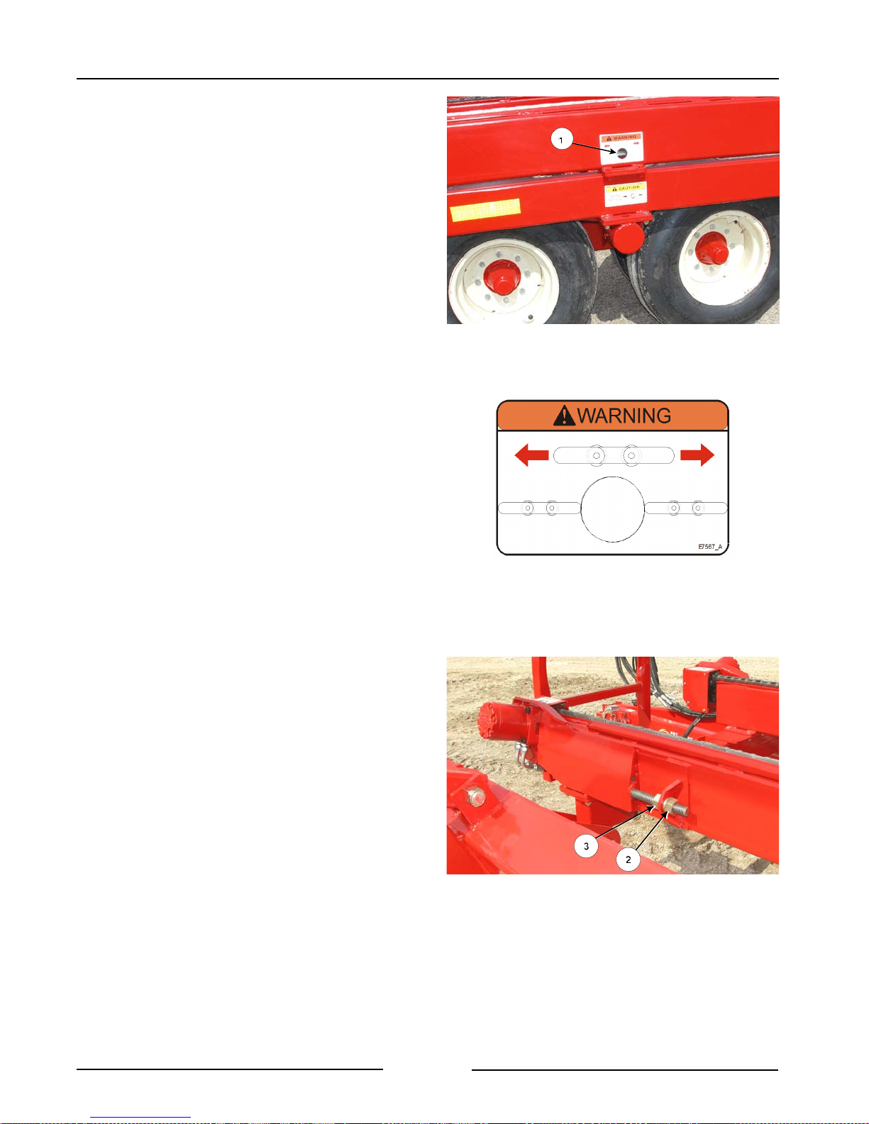
Section 5 - Maintaining the Bale Mover
Chain Adjustment Procedure
Check the tension on all 4 chains.
- The chain can be seen in the sight
hole (1) that is in the side of each rail.
- The chain should be in line with the
image of the chain that is on the
decal.
To adjust the chain tension:
- Loosen the nut (2) at the end of the
threaded rod on the motor mount.
Check Tension of All the Chains
Chain Tension
211061
E7567_A
- Adjust the chain tension by turning the
inside nut (3) until the bottom of the
chain is just off the bottom of the rail.
- Tighten the nut (2) at the end of the
threaded rod to secure the tension
setting.
Page 5-4
Adjust the Chain Tension
211066C
Page 44
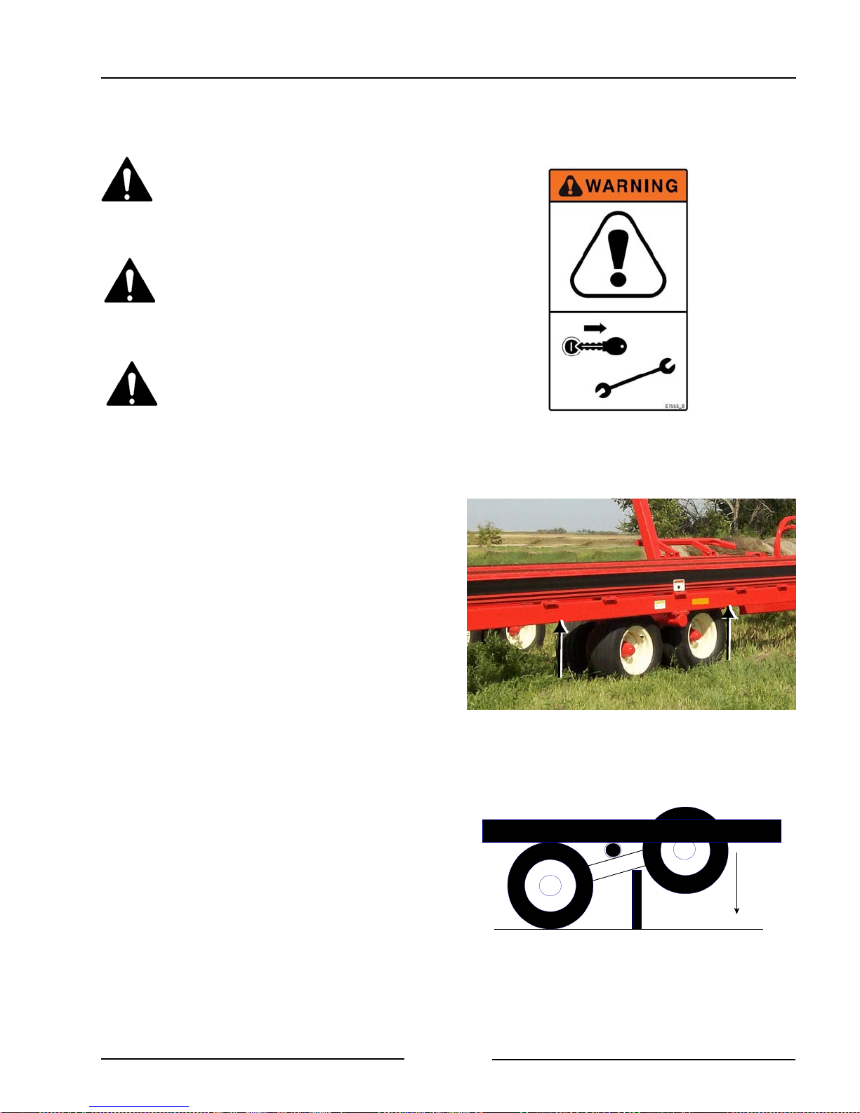
Section 5 - Maintaining the Bale Mover
Tire Changing Procedures
Before beginning, make sure the
tractor is turned off and the
parking brake is set.
Securely block the Bale Mover
before any work is done around or
under the machine.
Relieve hydraulic pressure and
disconnect the hydraulic hoses.
1. Hitch the Bale Mover to the tractor.
2. Block the Bale Mover tires on the
opposite side to prevent movement of the
Bale Mover.
3. Use two jacks under the main frame of
the Bale Mover (at the positions shown by
the arrows).
- Raise the side of the Bale Mover high
enough to be able to rotate the axle
so the tire can be removed.
4. Block the Bale Mover frame in this raised
position.
5. With the tires off the ground, rotate the
axle so the tire is below the frame.
- Block up the axle so that it cannot
rotate when the tire is removed. The
weight of the remaining tires will want
to rotate the axle.
Jack on Frame to Change Tire
Block to Prevent Rotation When Tire Removed
211067C
211069
6. Change the tire.
Page 5-5
Page 45

Section 5 - Maintaining the Bale Mover
Tire Pressure
Keep tires properly inflated to 90 psi/ 620
kPa. Tire damage may occur if tires are
under inflated.
Page 5-6
Page 46
Section 6 - Storing the Bale Mover
6.0 STORING THE BALE MOVER
1. Clean all the debris off the Bale Mover.
2. Lubricate all Bale Mover grease points
(See Section 5).
3. Tighten all bolts to the recommended
torque.
4. Check the Bale Mover for worn and
damaged parts. Replace as needed.
5. Touch-up the paint to prevent rusting.
6. Park the Bale Mover on level ground.
7. Lower the Bale Mover bed to be fully
resting on the frame.
Park on Level Ground
Lower Bed onto Frame
211075
211076
Page 6-1
Page 47
Section 6 - Storing the Bale Mover
8. Raise both lift arms to the full upright
position.
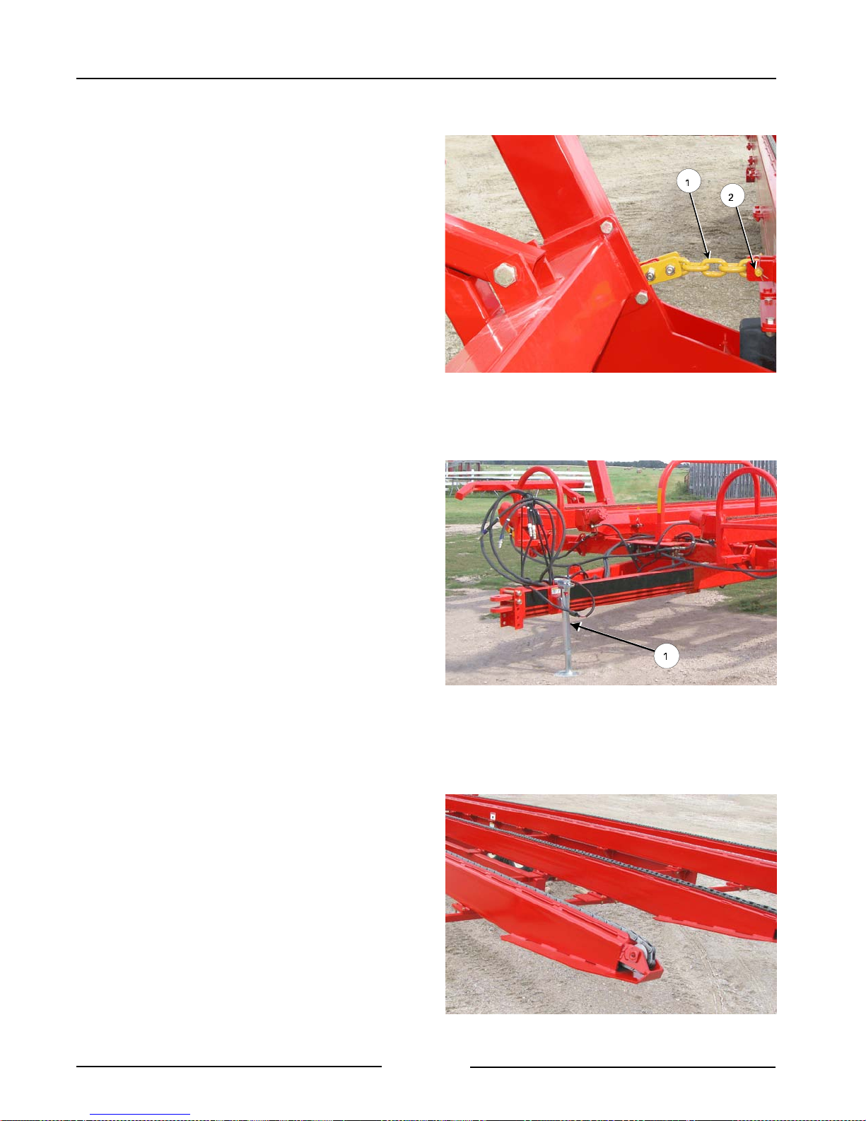
9. Fasten both lift arm transport chains (1) in
place to lock the arms.
- Fasten the chains with the pin (2) and
lock in place.
10. Remove the jack from the storage
position and place it onto the hitch.
- Pin the jack in place (1).
- Raise the hitch until the weight is
supported by the jack.
- Ensure that the jack is resting on solid
level ground or resting on a wood
block.
11. Disconnect the hitch from the tractor.
- Remove the hitch pin.
Fasten Lift Arm with Transport Chain
Raise the Hitch with the Jack
211036C
211077
12. Oil the bale chains with a rust
inhibiting oil or coating to prevent
weathering.
Page 6-2
Oil the Chains to Prevent Weathering
211038
Page 48
Section 6 - Storing the Bale Mover
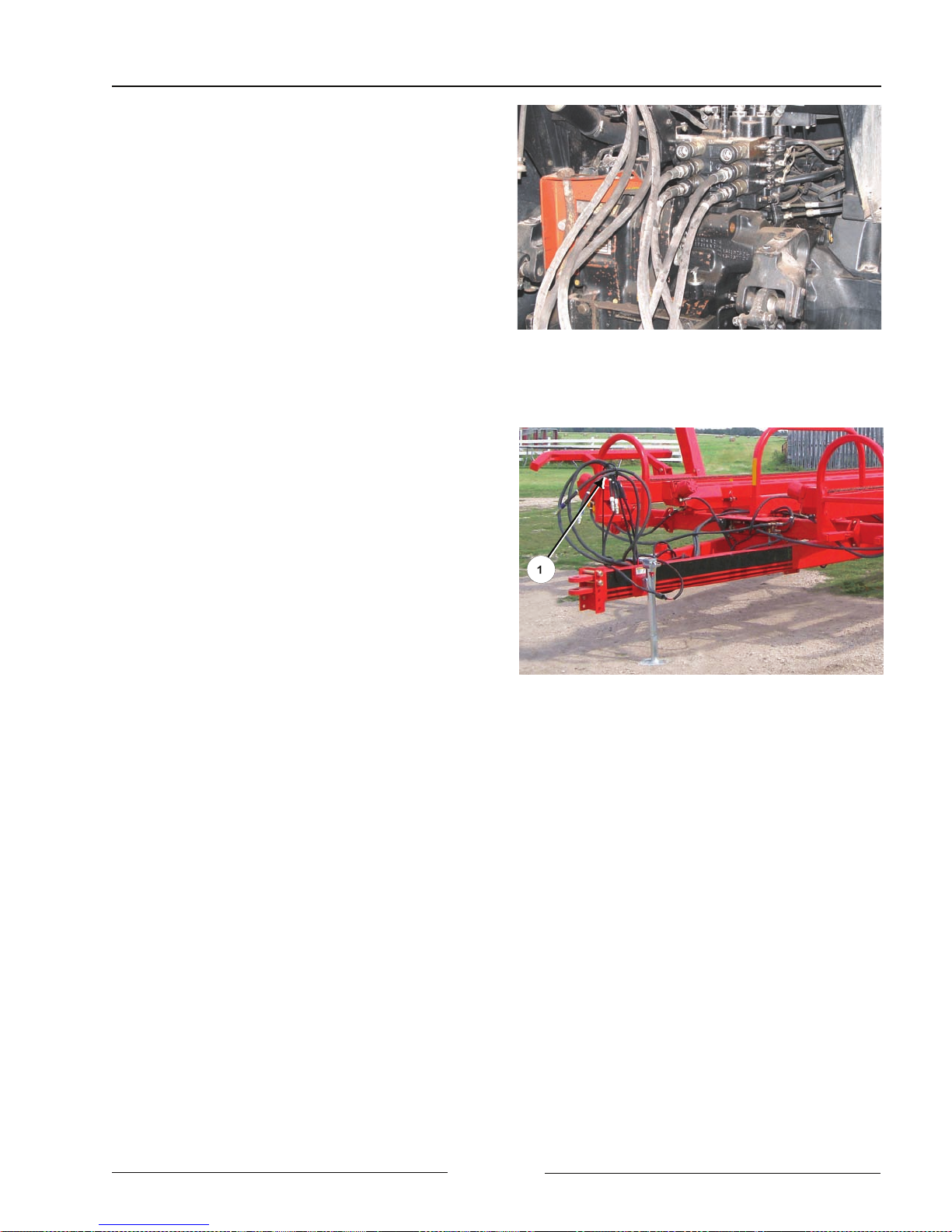
12. Relieve the pressure on the hydraulic
hoses and disconnect them.
13. Disconnect the electrical connection.
14. Remove the switch and cable from the
tractor cab. Store in a dry place.
15. Secure the hydraulic hoses and
electrical connectors to the hose
holder (1) on the hitch to keep them
off the ground and clean.
Disconnect Hydraulics and Lighting
Hydraulic Hoses and Electrical in Holder
108094C
211077C2
Page 6-3
Page 49

Section 6 - Storing the Bale Mover
This Page Left Blank
Page 6-4
Page 50

Section 7 - Specifications
7.0 BALE MOVER SPECIFICATIONS
Shipping Weight 9,660 lbs (4,382 kg)
Hitch Weight (empty) 1,740 lbs (789 kg)
Hitch Weight (Loaded) 3,423 lbs (1,553 kg)
Hitch Weight (Partially loaded - worst
5,576 lbs (2529 kg)
case)
GVW 38,000 lbs (17,236 kg)
Total Length 43’ 9¼” (13.34 m)
Bed Length 37’ (11.28 m)
Total Width (Loaded) 16’8”’ (5.08 m)
Total Width (Unloaded) 15' 1½" (4.61 m)
Bed Width 11’2” (3.4 m)
Total Height (Max) 12’ 3¼” (3.74 m)
Bed Height 3’3” (991 mm)
Maximum Capacity 16 of 4' long bales
14 of 5' long bales
Total bale weight - 23720 lb (10759 kg)
Tires 11L-15FI, F Ply
Horsepower Required 100 hp (75 kW)
Hydraulic Outlets 2
Hydraulic Pressure 2,500 psi. (17237 KPa)
Page 7-1
Page 51

Section 7 - Specifications
This Page Left Blank
Page 7-2
Page 52

Highline New Equipment Limited Warranty Policy
One (1) Year / 12 Months - Parts and Labour
Highline Mfg. Ltd. (hereinafter "Highline") warrants this new product of Highline's manufacturer to be free from
defects in material and workmanship, under normal use and service for one (1) full year after initial purchase/retail
sale. Highline will warrant its product for one (1) year parts and labour, if performed by a qualified Dealer. This
Limited Warranty shall apply only to complete machines of Highline's manufacture. Parts are covered by a separate
Limited Warranty.
EQUIPMENT AND ACCESSORIES NOT OF HIGHLINE'S MANUFACTURE ARE WARRANTED ONLY TO THE
EXTENT OF THE ORIGINAL MANUFACTURER'S WARRANTY AND SUBJECT TO THEIR ALLOWANCE TO
HIGHLINE ONLY IF FOUND DEFECTIVE BY SUCH MANUFACTURER.
During the Limited Warranty period specified above, any defect in material or workmanship in any warranted item
of Highline Equipment not excluded below shall be repaired or replaced at Highline's option without charge by any
authorized independent Highline Dealer. An authorized Dealer must make the warranty repair or replacement.
Labour in accordance with Highline's labour reimbursement policy. Highline reserves the right to supply
remanufactured replacement parts as it deems appropriate.
RETAIL PURCHASER RESPONSIBILITY
This Limited Warranty requires proper maintenance and periodic inspections of the Equipment as indicated in the
Operator's Manual furnished with each new Equipment. The cost of routine or required maintenance and services
is the responsibility of the retail purchaser. The retail purchaser is required to keep documented evidence that these
services were performed. This Highline New Equipment Limited Warranty may be subject to cancellation if the above
requirements are not performed.
EXCLUSIONS AND LIMITATIONS
The warranties contained herein shall NOT APPLY TO:
1. Any defect which was caused (in Highline's sole judgement) by other than normal use and service of the
Equipment, or by any of the following:
a. accident
b. misuse or negligence
c. overloading
d. of reasonable and proper maintenance
e. improper repair or installation
f. unsuitable storage
g. non-Highline approved alteration or modification
h. natural calamities
i. vandalism
j. parts or accessories installed on Equipment which were not manufactured or installed by Highline authorized
Dealers
k. the elements
l. collision or other accident.
2. Any Equipment whose identification numbers or marks have been altered or removed.
3. Any Equipment which any of the required or recommended periodic inspection or services have been performed
using parts not manufactured or supplied by Highline or meeting Highline Specifications including, but without
limitation, lubricants (oil, grease), belt lacings, and hydraulic fluids.
4. Any Equipment used in demonstrations not performed by a Highline Dealer. Warranty will be at the discretion
of Highline for all other demonstration warranty.
5. New Equipment delivered to the retail purchaser in which the warranty registration has not been completed and
returned to Highline within thirty (30) days from the date of purchase.
6. Any defect that was caused (in Highline's sole judgement) by operation of the Equipment not abiding by standard
operating procedures outlined in the Operator's Manual.
7. Tire Limited Warranties and support are the responsibility of the respective product's manufacturer.
8. Transportation costs, if any, of transporting to the Highline Dealer.
9. In no event shall Highline's liability exceed the purchase price of the product.
10. Highline shall not be liable to any person under any circumstances for any incidental or consequential damages
(including but not limited to, loss of profits, out of service time and damage to equipment which this equipment
may be attached) occurring for any reason at any time.
11. Diagnostic and overtime labour premiums are not covered under this Limited Warranty Policy.
Rev 3.2
Page 53

12. Depreciation damage caused by normal wear, lack of reasonable and proper maintenance, failure to follow
operating instructions, misuse, and/or lack of proper protection during storage.
13. Accessory systems and electronics not of Highline's manufacture are warranted only to the extent of such
manufacturer's respective Limited Warranty if any.
14. Wear items which are listed by product group below:
COMMON WEAR ITEMS
Roller chain, sprockets, clutches, shear bolts, clutch components, chains, gearbox housings bolts/torqued parts,
flails, feed roller belting, coupler chain, DRV couplers, bogie wheels, apron tines and hoses, blades and blade pans,
blade bolts and nuts, skid shoes, chain guards, clutches and clutch components.
PARTS WARRANTY
Parts replaced in the warranty period will receive the balance of the one year New Equipment Limited Warranty.
Replacement parts after the original machine warranty are warranted to be free from defects of material for ninety
(90) days or the part will be repaired or replaced, without labour coverage for removal and reinstallation.
EXCLUSION OF WARRANTIES
UNLESS OTHERWISE REQUIRED BY LAW, AND EXCEPT FOR THE WARRANTIES EXPRESSLY AND
SPECIFICALLY MADE HEREIN, HIGHLINE MAKES NO OTHER WARRANTIES, AND ANY POSSIBLE LIABILITY
OF HIGHLINE HEREIN UNDER IS IN LIEU OF ALL OTHER WARRANTIES, EXPRESS, IMPLIED, OR
STATUTORY, INCLUDING, BUT NOT LIMITED TO, ANY WARRANTIES OF MERCHANT ABILITY OR FITNESS
FOR A PARTICULAR PURPOSE. HIGHLINE RESERVES THE RIGHT TO MODIFY, ALTER AND IMPROVE ANY
PRODUCT WITHOUT INCURRING ANY OBLIGATION TO REPLACE ANY PRODUCT PREVIOUSLY SOLD WITH
SUCH MODIFICATION. NO PERSON IS AUTHORIZED TO GIVE ANY OTHER WARRANTY, OR TO ASSUME
ANY ADDITIONAL OBLIGATION ON HIGHLINE'S BEHALF.
Rev 3.2
 Loading...