

HighLine Bale Pro CFR651 Operator's Manual

®
Bale Pro
Complete Feed Ration
CFR651
O p e r a t o r s M a n u a l
E12033V3_A

®
BalePro
Complete Feed Ration 651
Bale Processor
Operator’s
Manual
Printed in Canada Copyright © 2018 by Highline Manufacturing Ltd. All rights reserved.
The content of this manual was based on the most current information available as of the date of copyright. It is the policy of
Highline Manufacturing Limited to improve and develop our products continually. We reserve the right to make changes or add
improvements, at any time, without incurring any obligation to make changes or improvements on machines previously sold.
Changes may not be reflected in this manual.
Starting at Serial Number CFR6510009
Highline Manufacturing Limited
HWY #27, P.O. Box 307
Vonda, SK S0K 4N0
Canada
Phone: 306.258.2233
Fax: 306.258.2010
Toll Free: 1.800.665.2010
E12033V3_A
103116

Highline Manufacturing Ltd. Complete Feed Ration 651 (CFR 651)
Highline Team Message
Congratulations on your purchase of the Complete Feed Ration 651 manufactured by Highline
Manufacturing Ltd.
This Operator's Manual has been prepared to provide information necessary for the safe and
efficient operation of your Complete Feed Ration 651 (CFR 651). In the manual you will find
safety procedures, maintenance routines and detailed operational instructions.
If you find that you require information not covered in this manual, please feel free to consult
your local dealer. Your dealer is always able to contact Highline for this technical information.
Highline Manufacturing Ltd. thanks and congratulates you for selecting a Complete Feed Ration
651 as your machine of choice.
Highline Manufacturing Ltd.

Table of Contents
Section 1 - Safety
Serial Number . . . . . . . . . . . . . . . . . . . . . . . . . . . . . 1
Safety Sign-off Form . . . . . . . . . . . . . . . . . . . . . . . . 2
Safety Alert Symbol . . . . . . . . . . . . . . . . . . . . . . . . . 3
General Safety . . . . . . . . . . . . . . . . . . . . . . . . . . . . 4
Section 2 - Transporting the CFR 651
Tractor Requirements . . . . . . . . . . . . . . . . . . . . . . . 2
Ensure the correct PTO speed . . . . . . . . . . . . . . . . 2
Adjust the tractor drawbar length . . . . . . . . . . . . . . 2
Lift the hitch . . . . . . . . . . . . . . . . . . . . . . . . . . . . . . . 3
Connect the hitch to tractor drawbar . . . . . . . . . . . . 3
Connect the safety chain . . . . . . . . . . . . . . . . . . . . 3
Hoses and wiring harness through the support arm 3
Attach driveline to PTO . . . . . . . . . . . . . . . . . . . . . . 4
Attach hydraulics . . . . . . . . . . . . . . . . . . . . . . . . . . . 5
Connect the lights . . . . . . . . . . . . . . . . . . . . . . . . . . 5
Jack in the storage location . . . . . . . . . . . . . . . . . . 5
Section 3 - Preparing the CFR 651
Park on level ground. . . . . . . . . . . . . . . . . . . . . . . . 1
Ensure all decals are clean & in place. . . . . . . . . . . 1
Slow Moving Vehicle (SMV) clean and visible . . . . . 1
Check the condition of the flail drum . . . . . . . . . . . . 1
Clean debris from the flail drum and processor tub . 2
Check the condition of the flails . . . . . . . . . . . . . . . . 2
Remove twine, netwrap around flail drum/bearings. 2
Check the condition of the feeder chain . . . . . . . . . 3
Check the tension of the feeder chain . . . . . . . . . . . 3
Adjust the height of the hitch tongue . . . . . . . . . . . . 4
Set the level of the lower discharge door. . . . . . . . . 4
Verify the position of the lower discharge door . . . 5
Remove material around the feeder chain bearings 5
Safety Decals . . . . . . . . . . . . . . . . . . . . . . . . . . . . . . . . . 4
Shutdown Procedure . . . . . . . . . . . . . . . . . . . . . . . . . . . . 9
Safety Decal Locations . . . . . . . . . . . . . . . . . . . . . . . . . 10
Adjust wheel stance settings . . . . . . . . . . . . . . . . . . . . . . 6
Check the condition of the tires . . . . . . . . . . . . . . . . . . . . 6
Raise the bale loading forks . . . . . . . . . . . . . . . . . . . . . . 7
Install the cylinder lock on the bale loading forks . . . . . . 7
Raise the discharge deflector door ................. 7
Install the discharge deflector door transport lock . . . . . . 7
Secure the rubber panel on door . . . . . . . . . . . . . . . . . . . 7
Slow Moving Vehicle (SMV) clean and visible . . . . . . . . . 8
Transport . . . . . . . . . . . . . . . . . . . . . . . . . . . . . . . . . . . . . 8
Transport Speed . . . . . . . . . . . . . . . . . . . . . . . . . . . . . . . 8
Check condition and tension of flail drum drive belt. . . . . 6
Adjust the bale loader forks width . . . . . . . . . . . . . . . . . 7
Inspect all hydraulic motors, cylinders and hoses . . . . . . 8
Inspect the wheels and tires . . . . . . . . . . . . . . . . . . . . . . 8
Check that the axle u-bolts are tight. . . . . . . . . . . . . . . . . 9
Remove twine built up around spindle and hub . . . . . . . 9
Driveline shields in place and in good repair . . . . . . . . . 9
Remove the flail drum lock pin . . . . . . . . . . . . . . . . . . . 10
Remove the fork cylinder lock . . . . . . . . . . . . . . . . . . . 10
Remove the nuts and washers from rubber panel . . . . . 11
Remove lock pin on the discharge deflector door . . . . 12
Lubricate grease fittings and check the fluid level . . . . 12
NetWrap or Twine Removal Procedure . . . . . . . . . . . . . 13
Section 4 - Operating the CFR 651
Unlock the flail drum . . . . . . . . . . . . . . . . . . . . . . . . 1
Set the aggression level of the flails . . . . . . . . . . . . 2
Set the speed of the feeder chain . . . . . . . . . . . . . . 3
Set the upper deflector door . . . . . . . . . . . . . . . . . . 4
Set the level of lower discharge door . . . . . . . . . . . 5
Load the bale into the processor tub . . . . . . . . . . . . 6
Load a second bale . . . . . . . . . . . . . . . . . . . . . . . . . 7
Section 5 - Maintaining the CFR 651
Lubrication . . . . . . . . . . . . . . . . . . . . . . . . . . . . . . . . 1
Visually Inspect Hydraulic Hoses/Fittings . . . . . . . . 3
Adjust the Feeder Chain Tension . . . . . . . . . . . . . . 4
Adjust the Belt Tension for the Flail Drum Drive . . . 5
Changing the Gearbox to Flail Drum Belt . . . . . . . . 7
Start PTO to engage the flail drum . . . . . . . . . . . . . . . . . 7
Begin processing material. . . . . . . . . . . . . . . . . . . . . . . . 8
Adjust the feeder chain speed . . . . . . . . . . . . . . . . . . . . . 8
Adjust the aggression level . . . . . . . . . . . . . . . . . . . . . . 9
Re-adjust the lower discharge door . . . . . . . . . . . . . . . . 9
Crossing ditches and steep inclines . . . . . . . . . . . . . . . 10
Making turns . . . . . . . . . . . . . . . . . . . . . . . . . . . . . . . . . 10
Check the Fluid Level in the Gearbox . . . . . . . . . . . . . . . 8
Gearbox Oil Changing Procedures . . . . . . . . . . . . . . . . . 9
Flail Replacement Procedure . . . . . . . . . . . . . . . . . . . . 10
Tires . . . . . . . . . . . . . . . . . . . . . . . . . . . . . . . . . . . . . . . 11
Axles . . . . . . . . . . . . . . . . . . . . . . . . . . . . . . . . . . . . . . . 11

Section 6 - Storing the CFR 651
Clean all the debris from the tub area . . . . . . . . . . . 1
Park the CFR 651 on level ground . . . . . . . . . . . . . . 1
Lubricate all CFR 651 grease points . . . . . . . . . . . . 1
Oil the feeder chains with a rust inhibiting oil . . . . . 1
Lock the CFR 651 flail drum . . . . . . . . . . . . . . . . . . . 2
Lower the forks to the ground . . . . . . . . . . . . . . . . . . 3
Raise the discharge deflector door . . . . . . . . . . . . . . 3
Install the discharge deflector door transport lock . . 3
Place the rubber into the tabs and fasten . . . . . . . . . 3
Place the jack onto the hitch . . . . . . . . . . . . . . . . . . 4
Remove the driveline from the tractor PTO shaft . . . 4
Section 7 - Troubleshooting
Section 8 - CFR 651 Specifications
Disconnect the safety chain . . . . . . . . . . . . . . . . . . . . . . 4
Disconnect the hitch . . . . . . . . . . . . . . . . . . . . . . . . . . . . 4
Relieve the pressure on the hydraulic hoses and
disconnect them. . . . . . . . . . . . . . . . . . . . . . . . . . . . . . . 4
Disconnect the electrical connection . . . . . . . . . . . . . . . 4
Secure the hydraulic hoses and electrical connector to the
hose holder . . . . . . . . . . . . . . . . . . . . . . . . . . . . . . . . . . 5
Place the driveline into the driveline support . . . . . . . . . 5
Change the oil in the gearbox . . . . . . . . . . . . . . . . . . . . . 5
Check for worn and damaged parts . . . . . . . . . . . . . . . . 5
Touch-up the p
aint to prevent rusting . . . . . . . . . . . . 5

GENERAL DESCRIPTION OF THE COMPLETE FEED RATION 651 (CFR 651)
The Complete Feed Ration 651 (CFR 651) is a machine to process round bales of hay or other
animal feed materials. When the CFR 651 is engaged, it uses power from the tractor PTO to
rotate a flail drum. The flails strike the round bale and process it into feed size materials or
animal bedding sized materials. The bale is rotated against the flails by a feeder chain.
The Complete Feed Ration (CFR 651) has forks on the rear of the machine that allow the CFR
651 to pick up and self-load a round bale into the processing tub. An additional bale may be
carried on the forks while the bale in the tub is being processed.
The amount of processing and chopping of material in the processing tub is adjusted by setting
the height of the guard rods. The height of the guard rods determine the level of aggression of
the flails acting on the round bale. The round bale is rotated by a feeder chain while the flail
drum turns to process the material. The rotation of the bale assists in the bale being processed
in an even manner.
The processed material is discharged from the CFR 651 on the right side of the machine. The
height and distance of discharge is adjusted by moving the lower discharge door. A top
discharge deflector door allows the processed material to be laid down into a feed bunk,
windrow or spread to different distances.
The Complete Feed Ration 651 has the option of adding a Feed Chopper for additional
processing of the feed materials. There is also the option of adding a Grain Tank to add feed
grains in a measured amount to the feed mix to achieve the feed ration needed for the animals.
The operator of the CFR 651 is located in the tractor cab to control the speed of driving and the
speed of operation of the CFR 651.
INTENDED USE OF THE COMPLETE FEED RATION 651 (CFR 651)
- The CFR 651 is designed to process animal feed and bedding materials from a
round bale.
- The CFR 651 is intended for use in farming applications.
- The CFR 651 is intended for off road use only.
- The CFR 651 is intended for use in locations away from people who could be
harmed by the discharged materials.
Any uses of the CFR 651 other than the above stated Intended Uses shall be considered
misuse of the CFR 651. This misuse shall include (but not limited to):
- Using the CFR 651 in non-farming applications
- Using the CFR 651 on public roads
- Using the CFR 651 around people or in public places
- Processing materials other than animal feed materials
Always use the CFR 651 according to the instructions contained in this Operator's Manual and
the safety and instruction decals on the machine.
Perform regular maintenance and repair to ensure that the CFR 651 operates safely and
efficiently.

This Page Left Blank
Section 1 - Safety
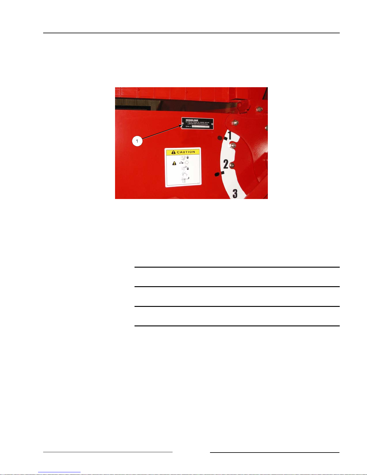
SERIAL NUMBER
Your serial number is found on the serial number plate attached to the tub wall of the Complete
Feed Ration 651.
Serial Plate Location
It is important to record the serial number for proof of ownership and for any service or
maintenance assistance.
215120C
Serial Number
Owner
Model
Date of Purchase
Page 1-1

Section 1 - Safety
SAFETY SIGN-OFF FORM
Highline Manufacturing Ltd. follows the general Safety Standards specified by the American
Society of Agricultural Engineers (ASAE) and the Occupational Safety and Health Administration
(OSHA). Anyone who will be operating and/or maintaining this equipment should read and
clearly understand all Safety, Operating and Maintenance information presented in this manual.
Do not operate or allow someone to operate this equipment until this information has been
reviewed. This information should be reviewed by all operators before the season start-up.
This sign-off sheet is provided for record keeping to indicate that the person working with the
equipment has read and understood the information in the Operator’s Manual and has been
instructed in the safe operation of the equipment.
Date Employee’s Signature Employer’s Signature
Page 1-2
Section 1 - Safety
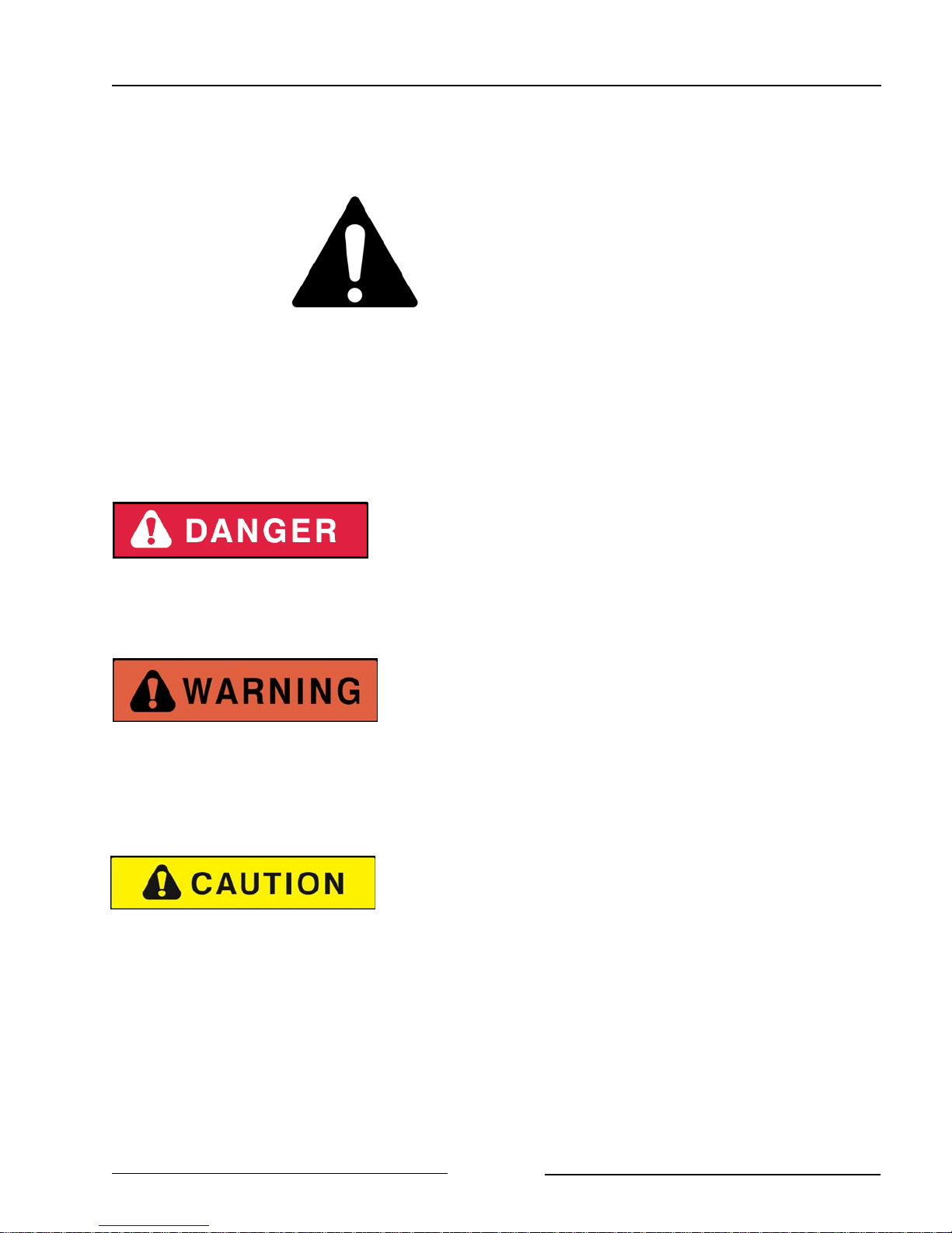
SAFETY ALERT SYMBOL
The Safety Alert Symbol means:
ATTENTION!
BECOME ALERT!
YOUR SAFETY IS INVOLVED!
The Safety Alert Symbol combined with a Signal Word alert to the presence of a hazard and the
degree of possible injury.
Indicates an imminently hazardous situation that, if not
avoided, WILL result in DEATH OR SERIOUS INJURY.
The color is Red with White lettering.
Indicates a potentially hazardous situation that, if not
avoided, COULD result in DEATH OR SERIOUS
INJURY, and includes hazards that are exposed when
guards are removed or unsafe practices. The color is
Orange with Black lettering.
Indicates a potentially hazardous situation that, if not
avoided, MAY result in MINOR INJURY. The color is
Yellow with Black lettering.
Page 1-3

Section 1 - Safety
GENERAL SAFETY
1. Ensure that anyone who is going to operate, maintain or work near the Complete Feed
Ration 651 is familiar with the recommended operating, maintenance procedures and safety
information contained in this manual and follows all the safety precautions.
2. In addition to the design and configuration of the equipment, hazard control and accident
prevention are dependent upon the awareness, concern, prudence and proper training of
personnel involved in the operation, transport, maintenance and storage of the machine.
3. The CFR 651 shall not be operated without all the guards in place.
SAFETY DECALS
1. Keep decals and signs clean and legible at all times.
2. Replace decals and signs that are damaged, missing or have become illegible.
3. Replaced parts that displayed a decal should also display the current decal.
4. Decals are available from the Highline Parts Department.
5. Be familiar with the decals, the type of warning and the area or function(s) related to the
area(s) that requires your awareness.
Page 1-4
Section 1 - Safety
DO NOT CONTACT ROTATING DRIVELINE
Contact with rotating driveline will cause serious injury or death.
Keep all driveline guards in place.
Securely attach drivelines at both ends.
Check that the driveline guards turn freely on the driveline.
DO NOT OPERATE WITH SHIELDS MISSING
Stop engine and ensure the PTO driveline is stopped before
working on driveline
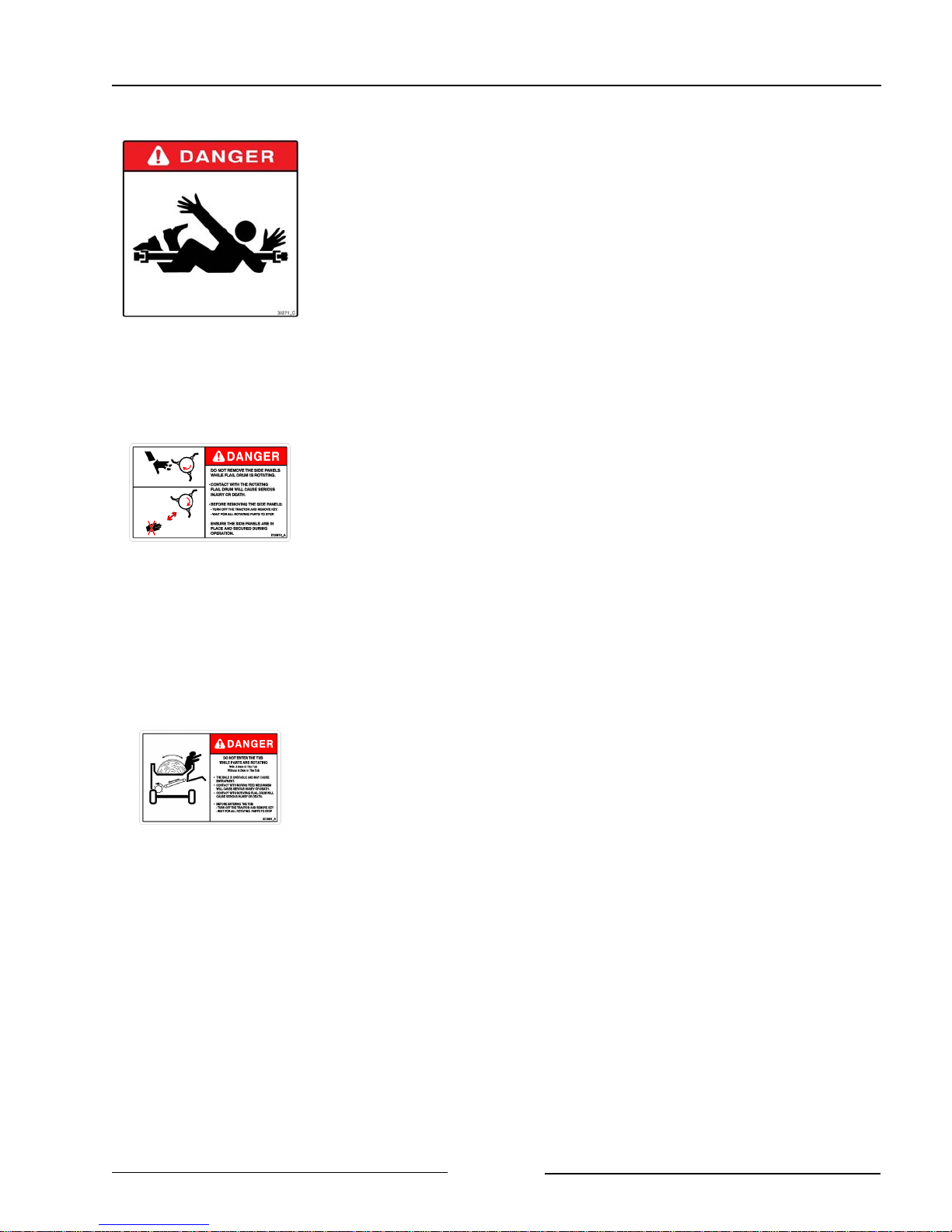
DO NOT REMOVE SIDE PANELS WHILE FLAIL DRUM IS
ROTATING
Contact with rotating parts can cause serious injury or death.
Before removing the side panels:
- Turn off the tractor and remove key.
- Wait for all rotating parts to stop.
Ensure the side panels are in place and secured during operation.
DO NOT ENTER TUB WHILE PARTS ARE ROTATING
- With a bale in the tub
- Without a bale in the tub
Before entering the tub
- Turn off the tractor and remove the key.
- Wait for rotating parts to stop
The bale is unstable and may cause entrapment.
Contact with the moving feed mechanism or rotating flail drum will
cause serious injury or death.
Page 1-5
Section 1 - Safety
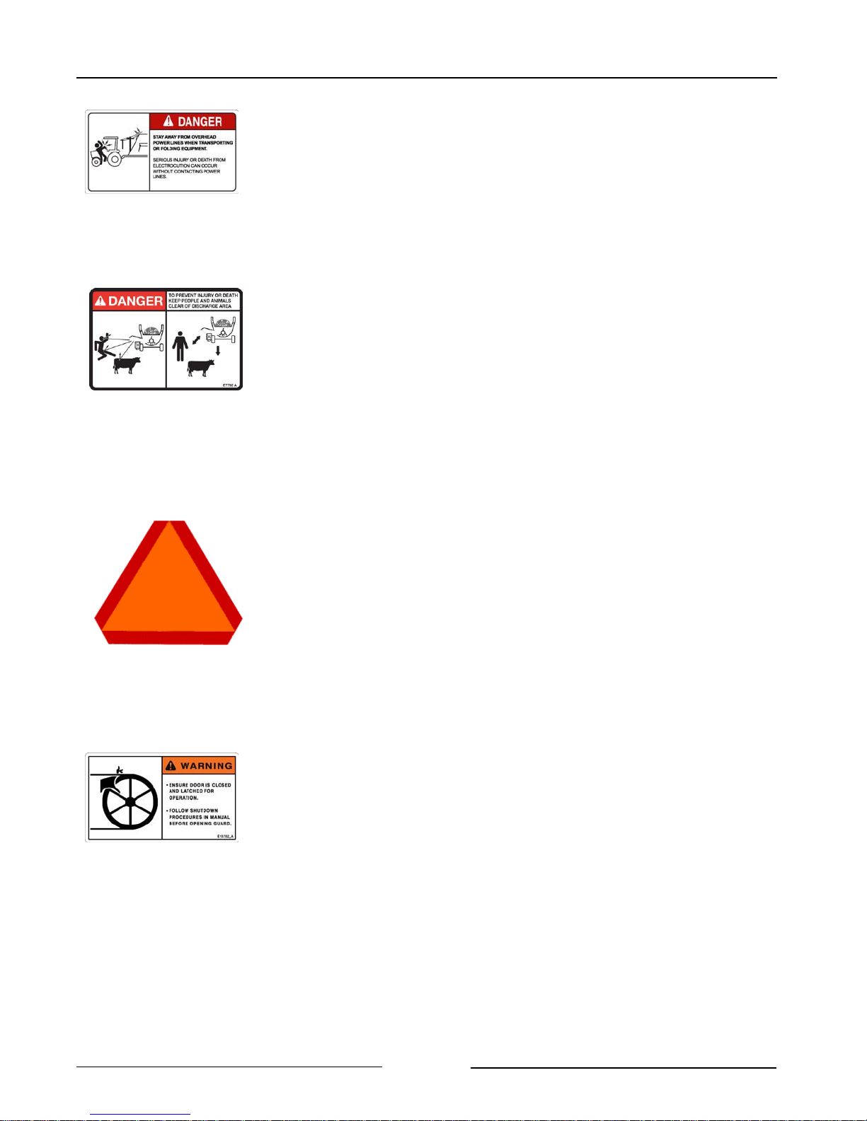
STAY AWAY FROM OVERHEAD POWER LINES
Stay away from overhead power lines when transporting
equipment.
Serious injury or death from electrocution can occur without
contacting power lines.
STAY BACK FROM AN OPERATING MACHINE WHICH CAN
DISCHARGE OBJECTS SEVERAL FEET
Stay clear from discharge side when PTO is engaged.
Thrown material or objects leaving the discharge area can cause
serious injury or death.
Do not operate within 100 ft (30m) of any person.
Keep all shields and guards in place.
ENSURE SLOW MOVING VEHICLE SIGN IS IN PLACE
Ensure the Slow Moving Vehicle sign is in place, clean and easily
visible.
Ensure the reflectors are in place, clean and easily visible.
DO NOT OPERATE WITH SHIELDS MISSING
Contact with the moving belt/sheaves or moving chain/sprockets
may cause serious injury or death.
Keep shields fastened in place.
Keep away from moving parts.
Do not stand or climb on the machine when operating.
Page 1-6
Section 1 - Safety
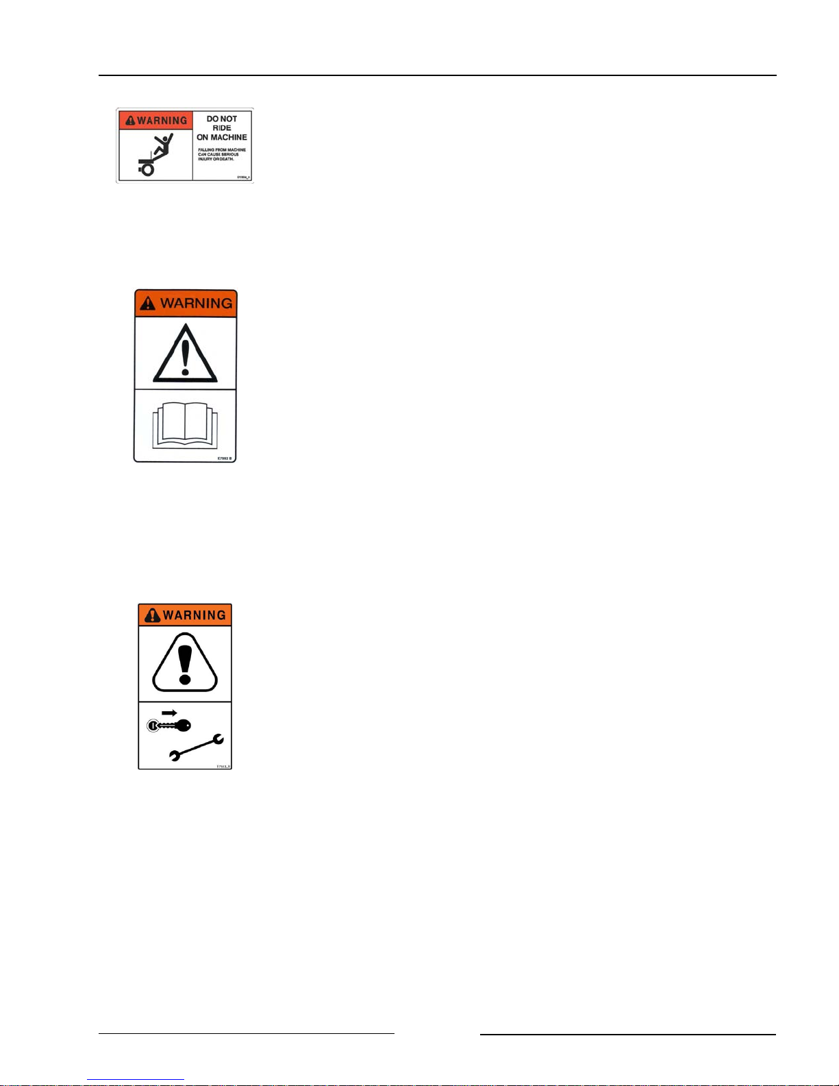
DO NOT RIDE ON MACHINE
Falling from the moving machine can cause serious injury or
death.
Falling from the operating machine can cause being entangled
under the machine or being injured by the machine.
READ, UNDERSTAND, AND FOLLOW SAFETY INSTRUCTIONS
Read, understand and follow all instructions and safety messages
included in this manual and on decals attached to the machine.
These instructions and safety messages contain important
information.
Allow only responsible, properly instructed individuals to operate
and service the machine.
Failure to follow the instructions and safety messages in this
manual and on the decals attached to the machine could result in
serious injury or death.
Keep all safety and instruction decals in good condition. Replace
any missing or damaged decals
SHUT DOWN THE TRACTOR BEFORE DISMOUNTING
TRACTOR
Shut down the tractor and remove the key before repairing,
servicing, lubricating or cleaning the machine.
Relieve all hydraulic pressure in the hoses before going near the
machine. Leave the hydraulics in the “float” position.
Page 1-7
Section 1 - Safety
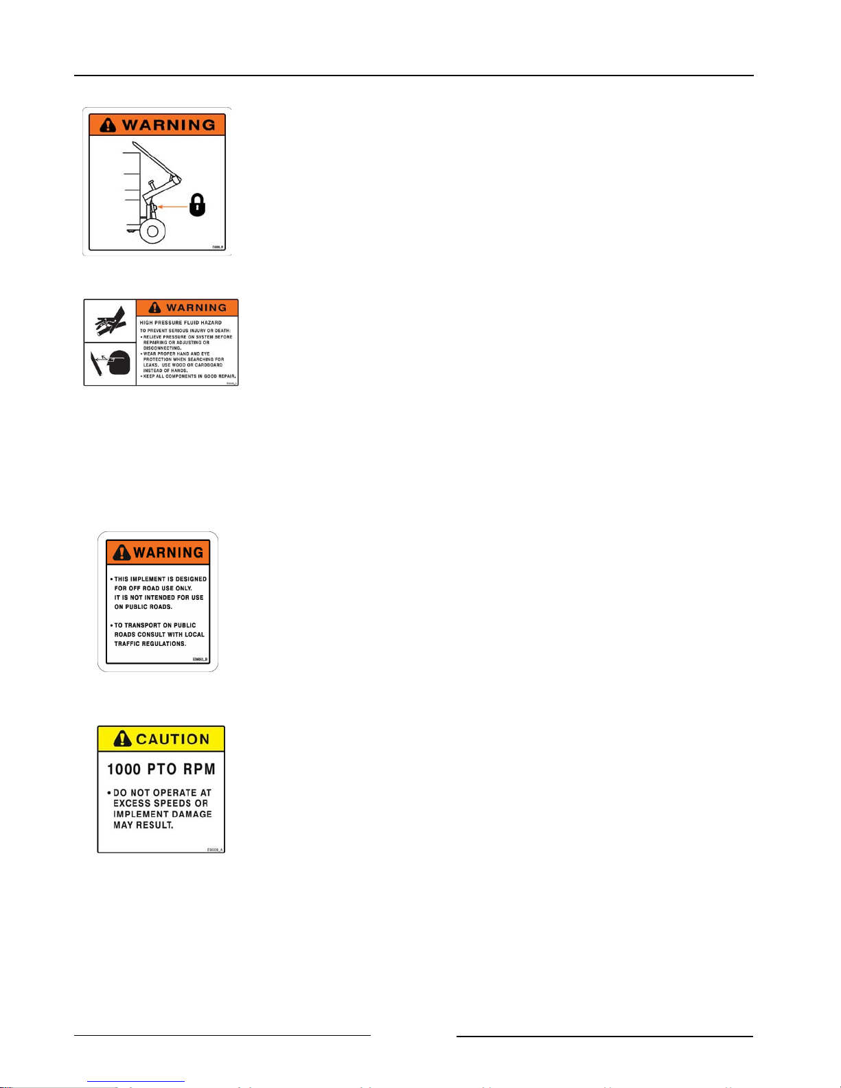
INSTALL CYLINDER LOCK BEFORE GOING UNDER RAISED
BALE FORKS
Install and secure the cylinder lock before going under raised bale
forks.
Install and secure cylinder lock before using the twine cutter.
USE PAPER OR CARDBOARD TO CHECK FOR HYDRAULIC
LEAKS
To prevent serious injury or death:
Relieve pressure on hydraulic system before repairing, adjusting or
disconnecting.
Wear proper hand and eye protection when searching for leaks.
Use wood or cardboard instead of hands.
Keep all components in good repair.
IMPLEMENT IS DESIGNED FOR OFF ROAD USE ONLY.
Do not transport with bales in the processor tub.
Do not transport with a bale loaded on the forks.
DO NOT EXCEED PTO SPEED
Do not operate at excess speeds or damage to the machine may
result.
Page 1-8
Section 1 - Safety
DO NOT EXCEED 80F TURNS IN OPERATION
Do not operate the Constant Velocity (CV) driveline at greater than
80F to prevent damage to the driveline.
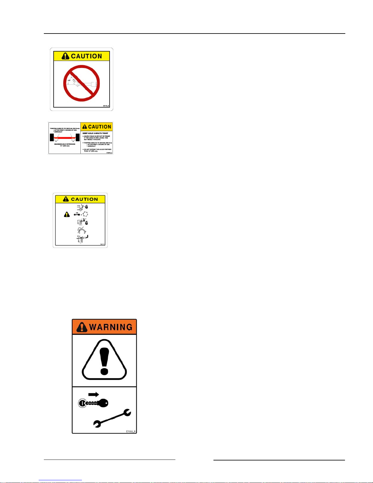
KEEP AXLE U-BOLTS TIGHT
axles could slide out of the frame if the u-bolts are loose. This may
result in injury/
Tighten u-bolts after first 5 hours of use.
Tighten u-bolts annually.
SHUT DOWN TRACTOR BEFORE USING TWINE CUTTER
Use the shutdown procedure to ensure no movement of the flail
drum will occur while cutting twine or netwrap.
LOCK FORKS AND FLAIL DRUM BEFORE USING TWINE
CUTTER
Lock forks in the upright position before going under the raised
forks.
Lock the flail drum to ensure no movement of the flail drum will
occur while cutting twine or netwrap.
SHUTDOWN PROCEDURE
For your safety and the safety of others, this shutdown
procedure mzust be followed before dismounting from
the tractor for inspecting, repairing, servicing, cleaning,
or lubricating the machine.
Step 1: Reduce the engine speed to idle.
Step 2: Disengage tractor power takeoff.
Step 3: Set tractor park brake.
Step 4: Lower bale loader forks to the ground.
Step 5: Shut off tractor engine and remove key.
Step 6: Cycle tractor controls to relieve any residual
circuit pressure.
Step 7: Wait for drum to stop turning.
Page 1-9
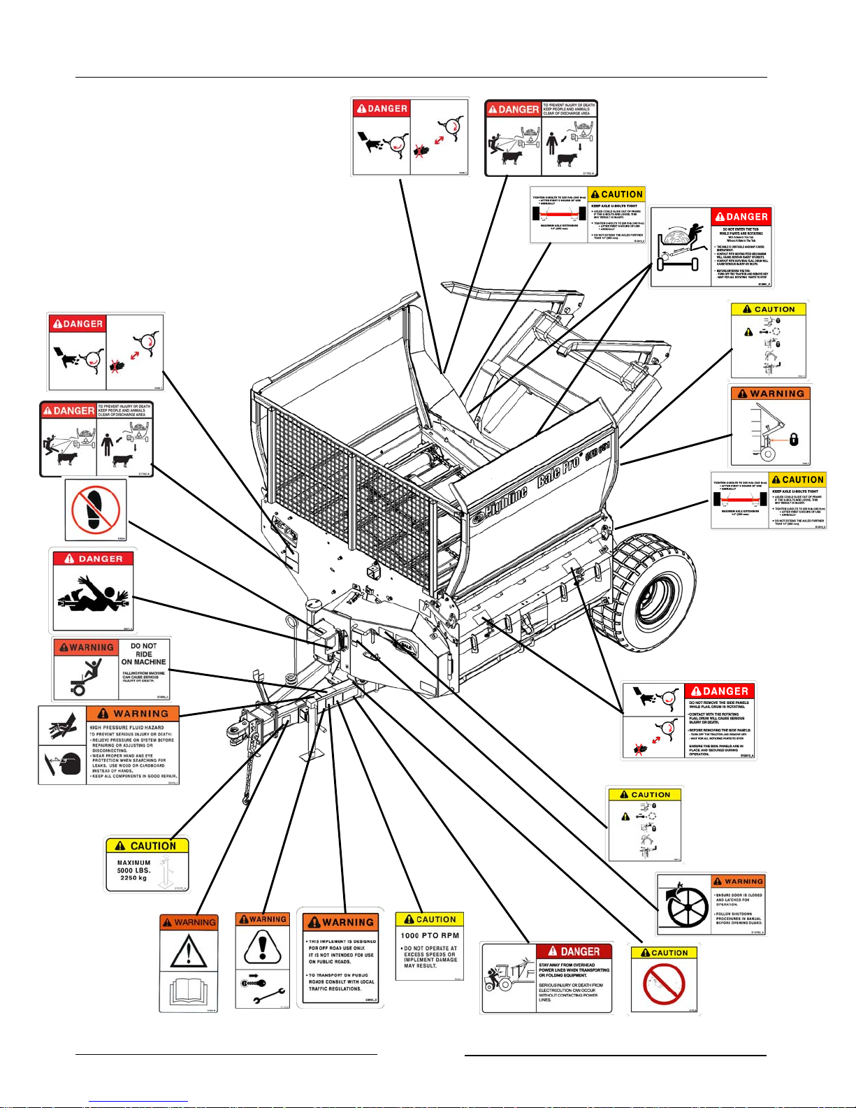
SAFETY DECAL LOCATIONS
Section 1 - Safety
216197
Page 1-10

Section 2 - Transporting the CFR 651
2.0 TRANSPORTING THE CFR 651
Only tow the CFR 651 behind a
properly sized and equipped
tractor which exceeds the loaded
weight of the CFR 651 by 50%.
Do not tow behind a truck or other
type of vehicle.
The CFR 651 is designed for off
road use only.
Do not transport on public roads
with bales in the processor tub.
Do not transport on public roads
with a bale loaded on the forks.
Check with local traffic regulations
to transport on public roads.
Stay away from overhead power
lines when transporting
equipment. Electrocution can
occur without contacting power
lines.
Do not allow any person to ride
on the tractor or CFR 651. Falling
off can result in serious injury or
death.
Keep the Axle U-Bolts Tight. Injury
could result if axles come out.
Page 2-1
Section 2 - Transporting the CFR 651
1. Tractor Requirements
- Roll Over Protection System (ROPS)
- Working seatbelts
- 1 3/8" 21 spline PTO
- PTO requirement
- refer to the "Specifications"
Section for the PTO requirements.
- 3 Selective Control Valves (SCV)
- An optional solenoid valve is
available for tractors with 2 SCV.
2. Ensure the correct PTO speed.
- Ensure that the tractor PTO speed
matches the CFR 651’s gearbox
speed of 1000 rpm.
- Do not attempt to operate the CFR
651 at a different PTO speed.
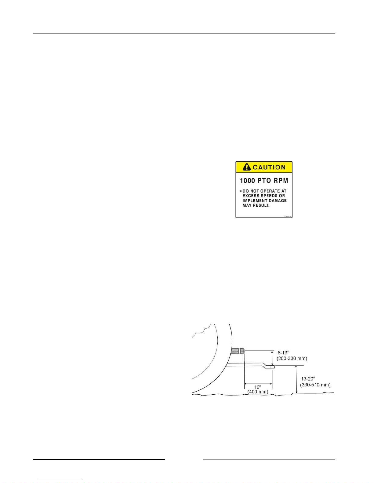
3. Adjust the tractor drawbar length.
- Set the drawbar length to 16" (406
mm) for a 1 3/8" 21 spline PTO.
- This length is measured from the tip of
the PTO shaft end to the center of the
drawbar hole. (Refer to your tractor’s
operator manual for drawbar
adjustment procedures.)
Note: To prevent damage to the tractor
drawbar, avoid traveling at high
speeds and over rough terrain.
Note: Do not use PTO adapters.
PTO adapters will cause a
driveline failure and possible
tractor damage. Your CFR 651
warranty will also be invalid.
Tractor Drawbar Adjustment
PTO Dimensions
Page 2-2
Section 2 - Transporting the CFR 651
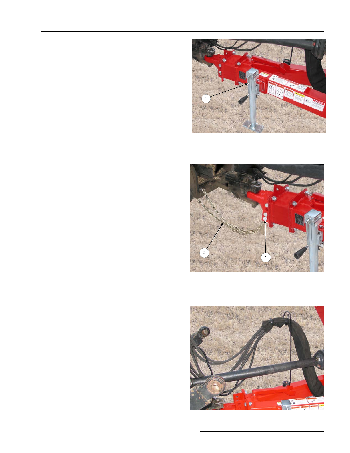
4. Lift the hitch.
- Lift the Hitch with the jack (1).
- The hitch is heavy. Do not attempt
to lift it without using the jack.
5. Connect the hitch to the tractor clevis
drawbar.
- Use a 1" (25 mm) pin.
- Secure with a hitch pin clip.
Lift Hitch with the Jack
213174C
6. Connect the safety chain
.
- Ensure the safety chain rating is equal
or greater than the gross weight of the
loaded CFR 651.
- Route the safety chain around the
lower safety chain bolt (1).
- Attach the chain to a secure location
on the tractor (2).
- Fasten the chain hook with the hook
lock.
7. Route the hydraulic hoses and wiring
harness through the hose support arm.
Connect Hitch & Safety Chain to Tractor
213175C
Page 2-3
Hoses and Electrical in Support Arm
211217
Section 2 - Transporting the CFR 651
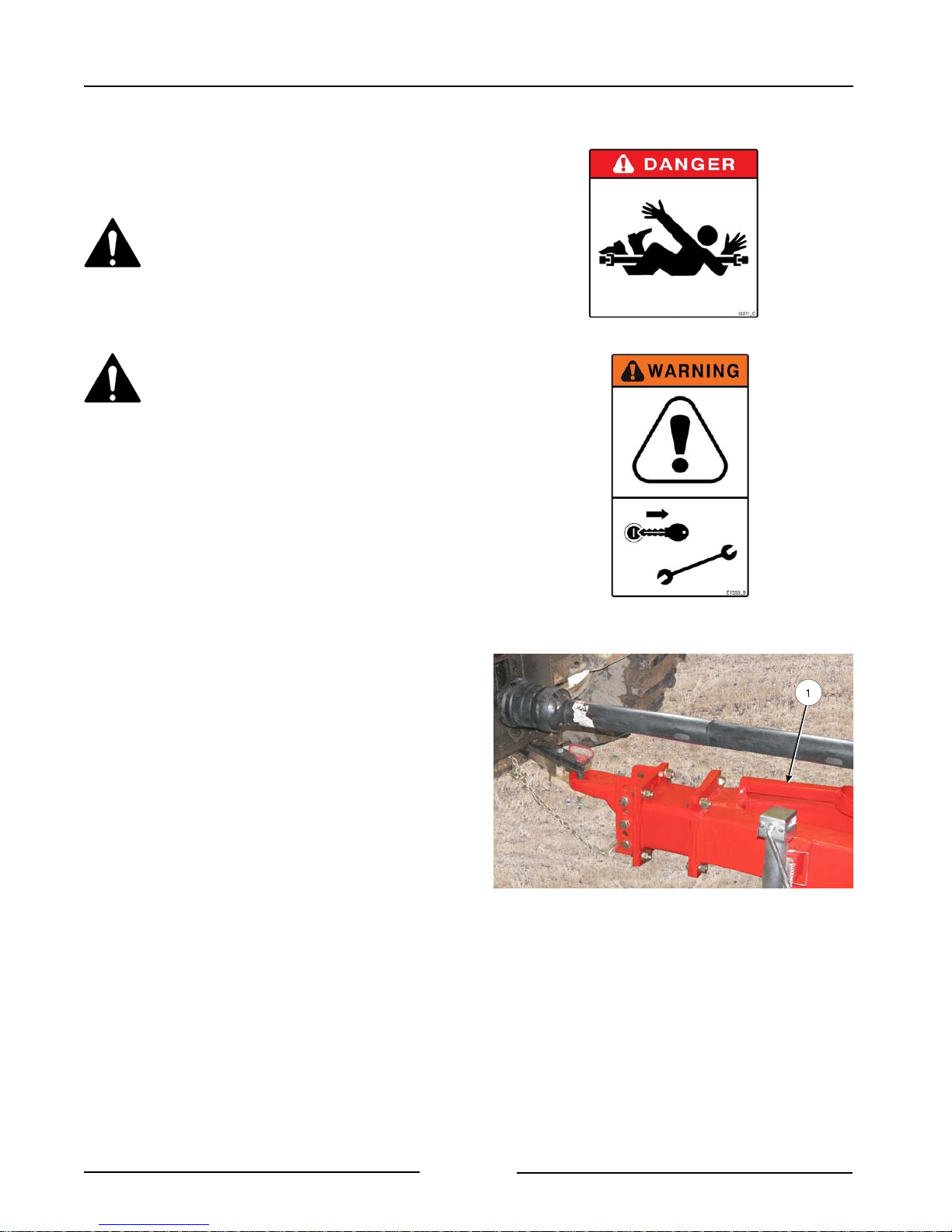
8. Attach driveline to PTO.
Note: Use the Category 6 drive line with the
Feed Chopper Option.
Shut off the tractor engine before
attaching PTO driveline.
Entanglement in the rotating
driveline can cause serious injury
or death.
The CFR 651 shall not be operated
without the driveline shields in
place.
- Shut off the tractor engine and
remove the key.
- Check that the driveline telescopes
easily and that the shields are in good
condition and rotate freely.
- Lift the tractor PTO shield.
- Support the driveline, pull back on the
yoke collar, align the splines by
rotating the CFR 651 driveline and
push the driveline into the tractor PTO
shaft until the collar snaps into place.
- Push and pull the yoke several times
to ensure the driveline is locked. Do
not pull on the collar as this will
release the lock.
- Lower the tractor & hitch PTO shields
into place.
- Fold down the PTO support holder (1).
- Failure to fold down the support
may result in damage to the
driveline.
Connect Driveline to PTO
213176C
Page 2-4
Section 2 - Transporting the CFR 651
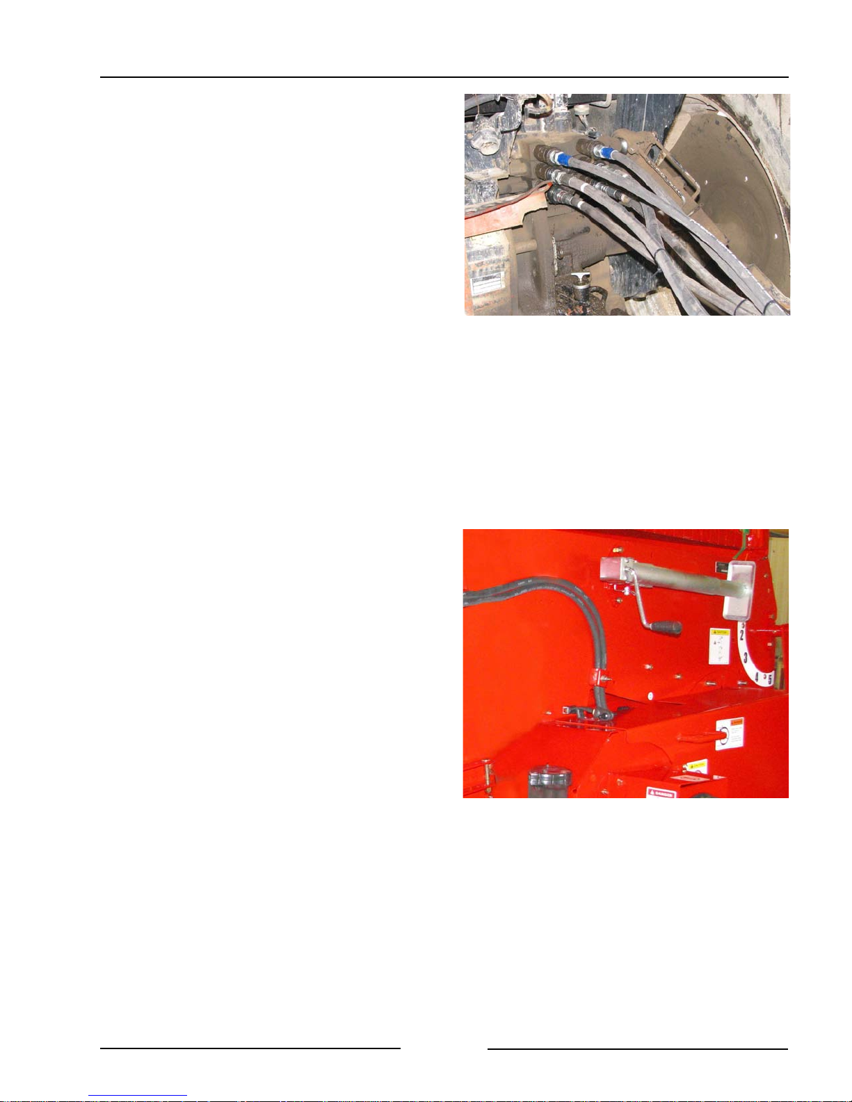
9. Attach hydraulics.
- Clean the end of the hoses and the
connection.
- Firmly push the hoses into the tractor
receptacle according to user
preference.
- Route the hoses so they do not
interfere with moving parts.
10. Connect the lights.
- Connect the light plug into the
appropriate tractor receptacle.
- Ensure the light cable does not
interfere with or contact moving parts.
11. Place the hitch jack in the storage
location on the front tub wall.
Attach Hydraulics
201199
Page 2-5
Hitch Jack in Storage Location
213014
Section 2 - Transporting the CFR 651
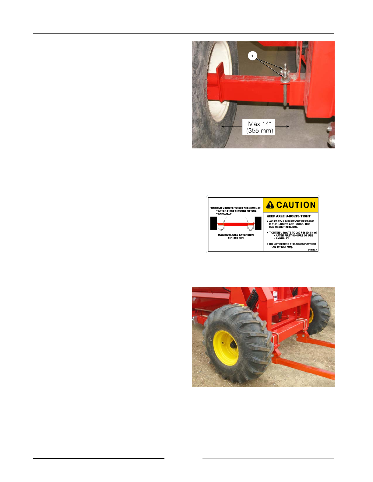
12. Adjust wheel stance settings.
- Increase the wheel stance to maintain
stability when working on hilly terrain
or rough ground.
Note: Ensure the bale processing tub is
empty before adjusting wheel
stance.
- Jack up the main axle under the
cylinder mount and support.
- Loosen the u-bolts (1) that hold the
axle tubes in place.
- Slide the axle to achieve the desired
wheel stance setting.
Wheel Stance Adjustment
212017C
Note: Maximum axle extension is 14"
(355 mm). Axles may bend if
extended beyond this amount.
- Tighten the u-bolts (1) to 250 lbf (339
Nm).
13. Check the condition of the tires.
- Ensure that the lug nuts have the
cone side of the lug nut against the
wheel rim.
- Torque the lug nuts to 121 lbf (164
Nm).
- Fill the tires to 24 psi (165 kPa).
Check the Tires
215126
Page 2-6
Section 2 - Transporting the CFR 651
14. Raise the bale loading forks to the
highest position.
15. Install the cylinder lock (1) on the
cylinder of the bale loading forks.
- Fasten the cylinder lock in place
with the pin (2).
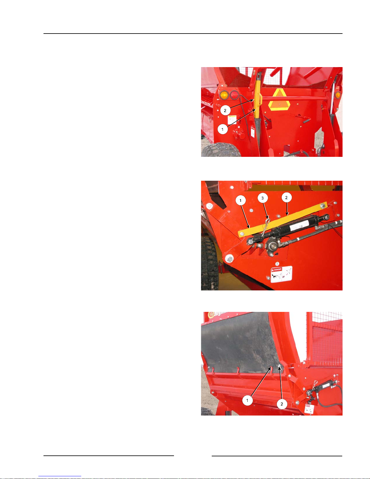
16. Raise the discharge deflector door to
the transport position.
- The discharge deflector door is
operated by a hydraulic cylinder.
Note: If the 2 remote option is
installed, the door cylinder will be
linked to the bale lift hydraulic circuit
through an electric solenoid
- Move the electric selector valve so
the hydraulic flow goes to the door
cylinder.
17. Install the discharge deflector door
transport lock.
- Rotate the short link (1) toward the
cylinder.
- Join the flats by inserting the pin of
the short flat into the longer flat (2).
Fork Cylinder Resting on Lock
Deflector Door Lock
216193C
212040C
- Install the clip pin (3).
18. Secure the rubber panel on door.
- Place the rubber panel into the tabs
(1) and fasten with a washer and nut
(2) to prevent the wind from blowing
the rubber panel from the tabs during
transport.
Page 2-7
Discharge Door Raised - Rubber Secured
212019C
 Loading...