

Page 1

Operation Manual
Predator SS
SIMPLIFIED STRETCH
LOW PROFILE
SERIAL NUMBER
Please refer to the serial number in all correspondence with Highlight or
any Highlight Distributor. This identifies your machine and will help in
our ability to quickly and efficiently respond to your needs.
OPERATION MANUAL NUMBER: PREDSS_LP / DEC-2017
Page 2

Predator SS Turntable Stretch Wrapper Operation Manual
Table of Contents
Table of Contents ............................................................................................................. 1
Table of Figures ................................................................................................................ 2
General Information ........................................................................................ 3
Safety Messages .............................................................................................................. 4
Introduction and Warranty ................................................................................................ 6
Revision History ................................................................................................................ 8
Specifications.................................................................................................. 9
Specifications ................................................................................................................. 10
System Overview Prints .................................................................................................. 11
System Description ......................................................................................................... 12
Installation & Adjustments ............................................................................. 13
Machine Placement ........................................................................................................ 14
Machine Set-Up .............................................................................................................. 15
Microprocessor Card ...................................................................................................... 18
Optional Scale Package ................................................................................................. 20
Operation Instructions ................................................................................... 23
Operator Controls ........................................................................................................... 24
Film Loading ................................................................................................................... 27
Machine Operating Instructions ...................................................................................... 29
Maintenance ................................................................................................. 30
Preventative Maintenance .............................................................................................. 31
Maintenance Schedule ................................................................................................... 34
Trouble-shooting ........................................................................................... 35
Self Test Troubleshooting ............................................................................................... 36
Troubleshooting Guide ................................................................................................... 39
Power Problems ............................................................................................................. 40
Turntable Problems ........................................................................................................ 41
Film Carriage Problems .................................................................................................. 42
Technical References ................................................................................... 43
Recommended Spare Parts ........................................................................................... 44
Electrical Drawings ......................................................................................................... 45
Mechanical Drawings...................................................................................................... 50
Notes ............................................................................................................ 64
Highlight Industries, Inc. ● 2694 Prairie SW, Wyoming, Mi 49519 ● 1-800-531-2465 1
Page 3

Predator SS Turntable Stretch Wrapper Operation Manual
Table of Figures
Figure 1: Predator SS Low Profile Overview Layout .......................................................... 11
Figure 2: Predator SS Low Profile Machine Description..................................................... 12
Figure 3: Bracket in the Shipping Position .......................................................................... 16
Figure 4: Bracket in its Operating Position ......................................................................... 16
Figure 5: Microprocessor Card for the Predator SS ........................................................... 18
Figure 6: Operator Controls Diagram for the Predator SS .................................................. 24
Figure 7: Film Loading/Threading Diagram ........................................................................ 27
Figure 8: Turntable Belt Adjustment ................................................................................... 32
Figure 9: Film Carriage Lift Chain Adjustment .................................................................... 33
Figure 10: Self Test Error Display ...................................................................................... 37
Highlight Industries, Inc. ● 2694 Prairie SW, Wyoming, Mi 49519 ● 1-800-531-2465 2
Page 4

1
Highlight Industries, Inc.
Predator SS Turntable Stretch Wrapper Operation Manual
General
Information
Page 5

General
Safety Messages
Information Predator SS Turntable Stretch Wrapper Operation Manual
For the best result with the Predator Turntable Stretch Wrapper, carefully read this manual
and all of the warning labels attached to the equipment before installing and operating it,
and follow instructions exactly. Keep this manual for machine reference.
Definitions and Symbols
High Voltage!
This symbol indicates high voltage. It calls your attention to items or
operations that could be dangerous to you or other persons operating
the equipment. Read the message and follow the instructions carefully.
Warning!
This symbol indicates a potentially hazardous situation which, if not
avoided, can result to bodily injury, or serious damage to the product.
Notes
This symbol indicates an area or subject of special merit, emphasizing
the equipment’s capabilities, common errors in operation or
maintenance, or other special instructions that can provide benefits to
users.
Highlight Industries, Inc. ● 2694 Prairie SW, Wyoming, Mi 49519 ● 1-800-531-2465 4
Page 6
General
Information Predator SS Turntable Stretch Wrapper Operation Manual
General Precautions – Read These First!
High Voltage!
Disconnect AC input power before checking components, performing
maintenance, cleaning up, and when the machine is not in use. Do NOT
connect or disconnect wires and connectors while power is applied to circuit.
High Voltage!
Wiring work should be carried out only by qualified personnel. Otherwise, there
is a danger of electric shock or fire.
High Voltage!
The user is responsible for conforming to all applicable code requirements with
respect to grounding all requirements. Do NOT use extension cords to operate
the equipment.
High Voltage!
Motor control equipment and electronic controllers are connected to hazardous
line voltages. When servicing drives and controllers, there may be exposed
components with housings or protrusions at or above line potential. Extreme
care should be taken to protect against shock.
Warning!
Loose clothing must NOT be worn while the machine is in operation. Stay clear
of moving parts while the machine is running.
Highlight Industries, Inc. ● 2694 Prairie SW, Wyoming, Mi 49519 ● 1-800-531-2465 5
Page 7

General
Introduction and Warranty
Information Predator SS Turntable Stretch Wrapper Operation Manual
Introduction
Thank you for your purchase of a Predator SS Turntable Stretch Wrapper! Designed for the
high volume industrial user the Predator SS will stretch wrap any load to the maximum
stretch level of any film with full independent control of the film force. This allows even light
unstable loads to be wrapped at the lowest possible cost and the maximum load holding
force.
Limited Warranty
Highlight Industries, Inc. warrants its Predator manufactured by it, and sold pursuant to this
order, will be of merchantable quality, free from defects in material and workmanship as
determined at the date of shipment, by generally recognized, applicable and accepted
practices and procedures in the industry, for a period of three (3) years from the Highlight
invoice date, under normal use and service.
When the Purchaser gives Highlight written notice of any alleged defect within the
applicable warranty period, Highlight will, at its option repair or replace the same free of
charge F.O.B. its manufacturing plant, installation not included. Equipment replaced under
the warranty shall have the same warranty as new equipment but does not extend the
warranty of the original equipment.
Satisfaction of this warranty, consistent with other provisions herein, will be limited to the
replacement or repair or modification of, or issuance of a credit for, the equipment involved,
at Highlight’s option.
Highlight neither assumes nor authorizes any person to assume for it any other obligation
in connection with the sale of Highlight’s equipment.
This warranty shall not apply to any equipment which has been repaired or altered by unauthorized personnel in any way so as to, in the judgment of Highlight, affect serviceability,
or which has been subjected to misuse, negligence, accident, or to equipment made by
Highlight which has been operated in a manner contrary to Highlight’s instructions.
In no event regardless of the cause, shall Highlight be liable for penalties or penalty clauses
of any description or any damages resulting from loss of profits, use of products or for any
incidental indirect or consequential damages, even if advised of the possibility of such
damages. This limitation of Highlight’s liability will apply regardless of the form of action,
whether in contract or tort, including negligence. Any action against Highlight must be
brought within twelve (12) months after cause of action accrues.
“This warranty in lieu of all other warranties whether expressed, implied or statutory
including implied warranties of merchantability of fitness or extends only to the buyer or
customer purchasing from Highlight Industries, Inc or an authorized distributor.”
Highlight Industries, Inc. ● 2694 Prairie SW, Wyoming, Mi 49519 ● 1-800-531-2465 6
Page 8

General
Information Predator SS Turntable Stretch Wrapper Operation Manual
About This Document
The purpose of this manual is to provide you with information necessary to install, operate,
troubleshoot, and maintain the Predator SS Turntable Stretch Wrapper. The audience for
this manual should have basic knowledge of mechanical and electronic components,
standard electrical wiring practices, and schematics symbols.
To guarantee safe operation of the equipment, carefully observe the safety messages
throughout this manual. Keep this operating manual and distribute it to all users for
reference.
Application Assistance
If any assistance is desired, contact the distributor from whom you have purchased the unit,
or call the number listed on the bottom of each page of this manual. To receive quick and
proper technical support for the equipment you have purchased, please be prepared to
provide the following information:
1. Machine Serial Number
2. Date of Purchase
3. Symptoms of any problems
Highlight Industries, Inc. ● 2694 Prairie SW, Wyoming, Mi 49519 ● 1-800-531-2465 7
Page 9

General
Revision
Revision Comment
Date of Revision
Initial Release
October 2014
Updated load cell part number
Feb 2015-RDU
Updated 110” part numbers
April 2015-RDU
Added summing board cover to scale TT
Jan 2018-RDU
Revision History
Information Predator SS Turntable Stretch Wrapper Operation Manual
Highlight Industries, Inc. ● 2694 Prairie SW, Wyoming, Mi 49519 ● 1-800-531-2465 8
Page 10

2
Highlight Industries, Inc.
Predator SS Turntable Stretch Wrapper Operation Manual
Specifications
Page 11

Specifications Predator SS Turntable Stretch Wrapper Operation Manual
LOW PROFILE
80” Wrap Height
110” Wrap Height
Length (inch)
98
98
Width (inch)
60
60
Height (inch)
91
132
Turntable Diameter (inch)
60
60
Turntable Height from Floor (inch)
3.25
3.25
Operation Space (inch)
105 x 75 x 120
105 x 75 x 132
Maximum Pallet Size (inch)
52 x 52 x 80
52 x 52 x 110
Shipping Weight (lbs)
1500
1700
Specifications
Machine Dimensions
Electrical Specifications
120VAC, 60Hz, Single Phase, 15Amp
Turntable
4,000 lbs Maximum Turntable Load Capacity
12 RPM Maximum Turntable Speed
20-30 Loads Per Hour
Optional Integrated Scale
Film Carriage
Adjustable Raise and Lower Speeds
Automatic Package Height Detection
Film Delivery
Infinite/Manual Film Force Adjustment
10 Inch Diameter Roll Capacity
20 Inch Height Roll Capacity (30 Inch Optional)
Highlight Industries, Inc. ● 2694 Prairie SW, Wyoming, Mi 49519 ● 1-800-531-2465 10
Page 12
Specifications Predator SS Turntable Stretch Wrapper Operation Manual
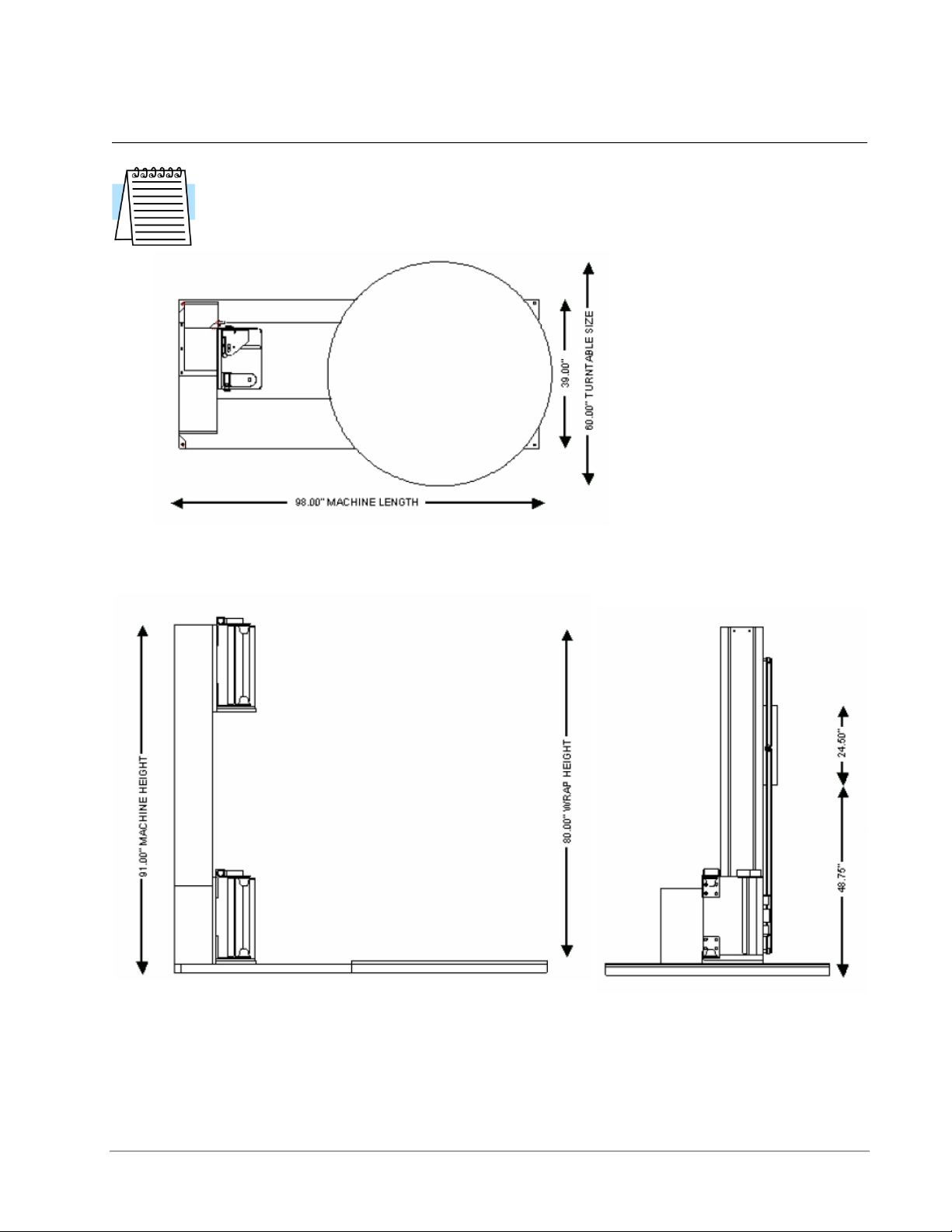
System Overview Prints
Note
Shown below are STANDARD assembly drawings. It may not reflect your
purchased system, especially when optional items are added. Refer to the
Technical References section of the manual for more detailed information.
Figure 1: Predator SS Low Profile Overview Layout
Highlight Industries, Inc. ● 2694 Prairie SW, Wyoming, Mi 49519 ● 1-800-531-2465 11
Page 13
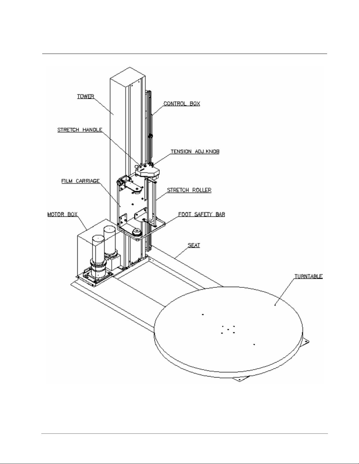
Specifications Predator SS Turntable Stretch Wrapper Operation Manual
System Description
Figure 2: Predator SS Low Profile Machine Description
Highlight Industries, Inc. ● 2694 Prairie SW, Wyoming, Mi 49519 ● 1-800-531-2465 12
Page 14

3
Highlight Industries, Inc.
Predator SS Turntable Stretch Wrapper Operation Manual
Installation &
Adjustments
Page 15

Installation & Adjustments Predator SS Turntable Stretch Wrapper Operation Manual
Machine Placement
Receiving and Inspections
The Predator Turntable Stretch Wrapper has gone through quality control tests at the
factory before shipment. Upon receiving, please do the following:
1. Inspect the entire machine for visual damage during shipment. If found, immediately
report this damage to the trucking line. Highlight Industries, Inc. has taken every
precaution during the packaging and loading of this equipment, however, it is YOUR
RESPONSIBILITY to inspect for damage before installation.
2. Make sure the part or serial number indicated on the machine corresponds with the
part number of your order.
Positioning of the Machine
Place the Predator Turntable Stretch Wrapper close to an area where you will be wrapping
your loads. Make sure that there is sufficient room to load/unload the machine and that you
do not stretch the power cable. Remember, you will need to plug the machine in to a
120VAC, 15-Amp outlet.
Floor Weight Bearing/Stress Tolerance
The floor must be able to bear the weight of the machine, the weight of the maximum load,
plus a safety factor. The floor must also be able to tolerate the stress of the machine’s
operation. If the fork trucks will operate on the same weight bearing area, add the weight of
the trucks to the weight bearing stress tolerance requirements.
The Predator can be installed on any type of floor constructions that meets the weight
bearing and stress tolerance requirements.
Warning!
The Predator must be anchored securely to the floor, using the type of anchor
recommended for your floor.
Highlight Industries, Inc. ● 2694 Prairie SW, Wyoming, Mi 49519 ● 1-800-531-2465 14
Page 16

Installation & Adjustments Predator SS Turntable Stretch Wrapper Operation Manual
Machine Set-Up
Unpacking and Moving the Machine
It is very important to read all instructions before undertaking any of these steps. The
following steps should help achieving a safe and quick machine set-up.
1. Place the skidded machine close to the designated wrap area. Remove all shipping
fasteners holding the machine to the pallet. The machine may be crated with the
tower tilted down with the motor cover and carriage removed for shipping purposes.
1.1. Stand up tower, pivoting about the pivot bracket at the base of the tower. Once
upright align 5 bolts at tower base to frame and tighten.
1.2. Remove 4 lower bolts from carriage mount bracket – leave the top 2 bolts loose but
in place. Align keyholes on carriage back over top 2 bolts in carriage mount bracket
and hang carriage. Install and tighten all 6 mounting bolts.
1.3. The carriage photo eye bracket may need to be unbolted from its shipping position
(Figure 3) to its operating position (Figure 4).
1.4. Mount motor cover in place over turntable and carriage lift motors with provided
fasteners.
1.5. Re-connect wiring to carriage if removed for shipping.
2. Place the forks of the forklift through the tubes provided on the base of the machine,
remove the machine from the shipping skids, and place it in the designated wrap
area.
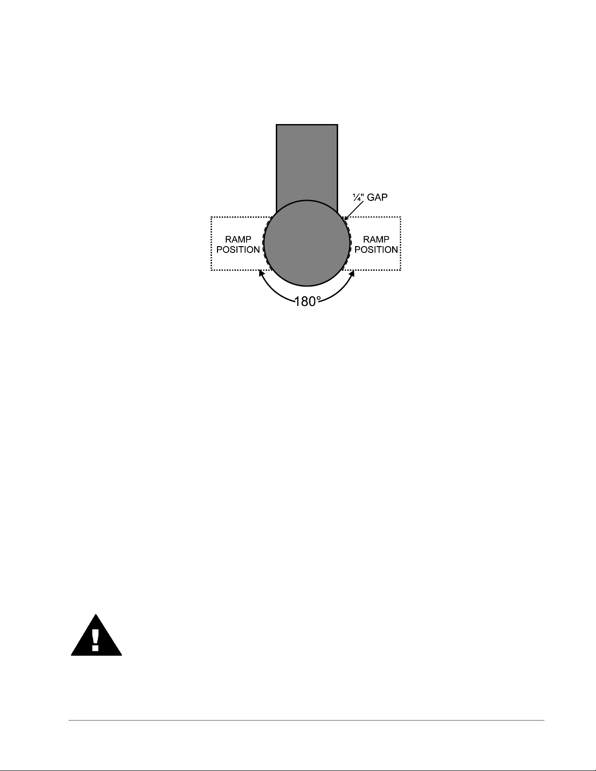
3. If the OPTIONAL ramp (Part Number #600086) is purchased:
Select a ramp position as illustrated below. The ramp can be positioned anywhere in
a 180° rotation around the front of the turntable. There should be ¼” gap between
the turntable and the ramp. The ramp should be fully supported by the floor. Both the
ramp and the machine should be lagged to the floor.
Highlight Industries, Inc. ● 2694 Prairie SW, Wyoming, Mi 49519 ● 1-800-531-2465 15
Page 17
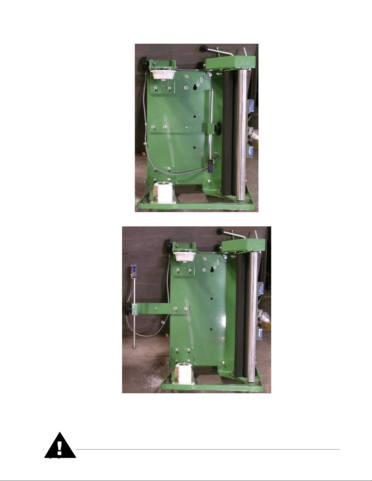
Installation & Adjustments Predator SS Turntable Stretch Wrapper Operation Manual
Figure 3: Bracket in the Shipping Position
Figure 4: Bracket in its Operating Position
Highlight Industries, Inc. ● 2694 Prairie SW, Wyoming, Mi 49519 ● 1-800-531-2465 16
Page 18
Installation & Adjustments Predator SS Turntable Stretch Wrapper Operation Manual
Warning!
It is very important that the machine be leveled. Uneven floors will cause premature
turntable support roller failure.
Figure 5: Ramp Position for the Predator SS Low Profile
Power and Control Wiring Checks
1. Using a volt meter, check the AC voltage coming to the machine and insure the
proper voltage is present.
2. Make sure the Emergency Stop button on the operator panel is fully pressed in. Turn
the disconnect switch to the ON position. Power should be applied to the drive
board, operating touch-panel, photoelectric sensors, switches, and LED’s.
3. Press the Emergency Stop button. Make sure all machine power is completely
removed when the Emergency Stop button is depressed. Pull the Emergency Stop
button out to resume.
4. Open the electric control box. Make sure all machine power is completely removed
when the electrical control box is open. Close the electrical control box to resume.
5. Trip the carriage foot security bar. Make sure all machine power is completely
removed when the carriage foot security bar is tripped. Clear the bar to resume.
Warning!
Ensure that the Emergency Stop button light is ON when the button is pushed
in and OFF when the button is pulled out.
Highlight Industries, Inc. ● 2694 Prairie SW, Wyoming, Mi 49519 ● 1-800-531-2465 17
Page 19
Installation & Adjustments Predator SS Turntable Stretch Wrapper Operation Manual
Microprocessor Card
Microprocessor Card Description
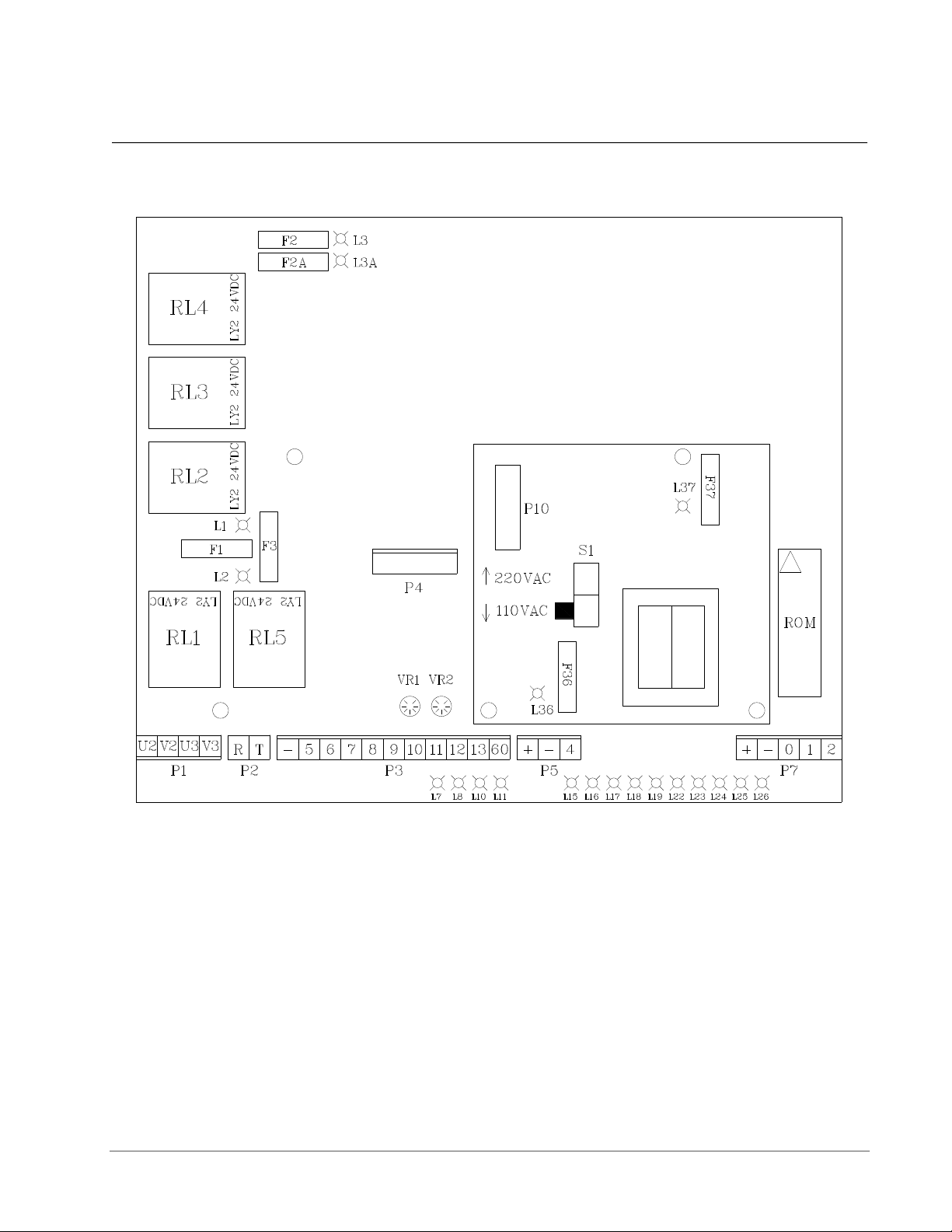
Figure 5: Microprocessor Card for the Predator SS
S1: Operating voltage selector (220 VAC or 110 VAC)
Connector P1: Turntable/Film Carriage Relay Output
Connector P2: Power Input
Connector P3: Operator Panel Input
Connector P4/P10: Transformer Input/Output
Connector P5: Turntable Proximity Sensor Input
Connector P7: Film Carriage Limit Switches Input
Relay 1: Film Carriage Down
Relay 2: Film Carriage Up
Highlight Industries, Inc. ● 2694 Prairie SW, Wyoming, Mi 49519 ● 1-800-531-2465 18
Page 20

Installation & Adjustments Predator SS Turntable Stretch Wrapper Operation Manual
Relay 3: Turntable/Film Carriage Stop
Relay 4: Power Input
Relay 5: Turntable Running
Fuse 1: Carriage Motor (5 Amp)
Fuse 2/2A: Power Input (10 Amp)
Fuse 3: Turntable Motor (5 Amp)
Fuse 6: Transformer Input (1 Amp)
Fuse 7: Transformer Output (1 Amp)
LED 1 is ON: Film Carriage Motor fuse is blown
LED 2 is ON: Turntable Motor fuse is blown
LED 3/3A is ON: Power Input fuse is blown
LED 7 is ON: Cycle starts
LED 8 is ON: Film Carriage is moving up
LED 10 is ON: Film Carriage is moving down
LED 11 is ON: Turntable is rotating
LED 15 is ON: Start Button is pushed
LED 16 is ON: Pause Button is pushed
LED 19 is ON: Package Height Photo Sensor is unblocked
LED 23 is ON: Carriage Max Up Limit Switch is not tripped
LED 24 is ON: Carriage Max Down Limit Switch is tripped
LED 25 is ON: Emergency Stop Button is not pushed
LED 26 is ON: Turntable Home/Count proximity switch is blocked
LED 36 is ON: Transformer Input/Output is blown
VR1: Film Carriage Max Speed setting
VR2: Turntable Max Speed setting
Replacing Microprocessor Card
1. Turn the disconnect switch to OFF position.
2. Removed the old microprocessor card by pulling all connectors off and loosening the
four mounting screws.
3. Install the new microprocessor card; connect all connectors and tighten the
mounting screws.
4. Turn the disconnect switch to ON position. The display should show “- -“. If not,
check all connectors and fuses again.
Highlight Industries, Inc. ● 2694 Prairie SW, Wyoming, Mi 49519 ● 1-800-531-2465 19
Page 21

Installation & Adjustments Predator SS Turntable Stretch Wrapper Operation Manual
Optional Scale Package
The optional scale package allows the user to quickly measure the weight of the package
placed on the machine. To operate correctly and efficiently the scale needs to be
configured with the correct settings. Below are the instructions on how to re-configure the
scale and the settings that have been pre-programmed. Re-configuring the scale is not
required unless there is a problem with the existing scale or a new scale is added to the
machine. Refer to the scale manual for more information.
Note
Changing the scale parameters to values other than the Highlight
recommended values may result in poor scale operation.
Navigating the Scale Menu
Step 1: Turn the scale display over so you are looking from above down at the back side of
the scale and turn off the scale power.
Step 2: Remove the two small screws holding a small plate on the back of the scale.
Step 3: Looking down at the scale, move the switch under the plate to the right.
Step 4: Turn the scale power back on.
Step 5: Press the “PRINT / >>” button until the desired setting appears on the screen.
Step 6: Press the “ZERO” button to enter the parameter set-up.
Step 7: Press the “PRINT / >>” button until the display reads the correct setting and press
the “SET / NET” button.
Step 8: Turn the power back off, move the switch under the plate to the left, and turn the
power back on.
Step 9: Replace the screws on the back cover and retighten the scale swivel grips on the
side.
Step 10: The scale is now ready to use.
Highlight Industries, Inc. ● 2694 Prairie SW, Wyoming, Mi 49519 ● 1-800-531-2465 20
Page 22

Installation & Adjustments Predator SS Turntable Stretch Wrapper Operation Manual
Name/Code
Description
Highlight
Recommended
Value
F1:
Graduations
Specifies the number of full-scale graduations. Value
should be consistent with legal requirements and
environmental limits on the useful system resolution.
5000
F2: Span
Gain
Span Gain is related to A/D integration time. The larger the
span gain, the higher the internal resolution, but the slower
the update speed. Note that the scale must be recalibrated whenever this parameter is altered. See
Appendix C in the scales manual for more information.
100
F3: Zero
Track Band
Selects the range within which the scale will automatically
zero. Note that the scale must be in a standstill to zero the
scale.
3
F4: Zero
Range
Selects the range within which the scale may be zeroed.
Note that the indicator must be in standstill to zero the
scale.
100
F5: Motion
Band
Sets the level at which motion is detected by comparing
the present display update with the previous one. If motion
is not detected for two seconds or more, scale is in
standstill and can process a Print or Zero command.
Maximum value varies depending on local regulations
1
F6: Digital
Filter
Averages weight readings to produce higher stability but
the slower the indicator’s response time. Choose 8 unless
a very fast response is needed.
8
F7: Overload
Limit
Selects the desired formula which determines the point at
which the indicator shows overload. All selections are
based on the primary unit selected in F8.
2%
F8:
Calibration
Unit
Selects the primary base unit to be used in the calibration
process. Also the default unit for normal operation. 1 =
pounds, 2 = kilograms.
1
F9: Display
Divisions
Determines the desired weight increments. Value should
be consistent with legal requirements.
1
F10: Decimal
Point
Determines the location of the decimal point.
0
F16: Zero
Calibration
Places the scale in a Zero Calibration routine.
See below.
F17: Span
Calibration
Places the scale in a Span Calibration routine. See below.
See below.
Highlight Recommended Configuration Values:
Note
Changing the scale parameters to values other than the Highlight recommended
values may result in poor scale operation.
Highlight Industries, Inc. ● 2694 Prairie SW, Wyoming, Mi 49519 ● 1-800-531-2465 21
Page 23

Installation & Adjustments Predator SS Turntable Stretch Wrapper Operation Manual
Scale Calibration Procedure
Note
Highlight Industries, Inc calibrates the scale before shipment using known
weights. The values stored in theses settings are custom per scale and
machine. Do not change these values unless directed to do so by Highlight
personnel.
Step 1: Navigate the scale menu to parameter “F 16.”
Step 2: Press the “ZERO” button ONCE. This enters the Zero Calibration Menu. The
display will momentarily show “C 0” followed by a value.
Step 3: After making sure that there are no test weights on the machine press the “ZERO”
button again. The display will zero.
Step 4: Press the “SET / NET” button to save the zero point value. The display will show
“EndC0” momentarily then revert to parameter F16.
Step 5: Navigate to parameter “F 17.”
Step 6: Press the “ZERO” button ONCE. This enters the Span Calibration Menu. The
display will momentarily show “C 1” followed by a value with one flashing digit. This value
will be zero with the decimal point parameter selected in F10.
Step 7: Place a known weight on the machine. Ensure that the test weight is below the
maximum capacity of the scale and above 1% of the maximum capacity of the scale.
Step 8: Key in the weight of the test weight using the buttons on the screen. Press the
“TARE / <<” button to select the digit to the left of the current position. Press “PRINT / >>”
to select the digit to the right of the current position. Press “UNITS” to increase the value of
the digit and press “ZERO” to decrease the value of a digit.
Step 9: Once the weight of the test weight is keyed in exactly, press the “SET / NET” button
to save the value. If the calibration was successful the display will read “EndC1”
momentarily, and then revert back to “F17”. If “Err0” is displayed the test weight is larger
than the full capacity of the scale. If “Err1” is displayed the test weight is below 1% of the
full capacity of the scale. If “Err2” is displayed the internal resolution of the scale is not high
enough to accept the calibration value.
Highlight Industries, Inc. ● 2694 Prairie SW, Wyoming, Mi 49519 ● 1-800-531-2465 22
Page 24

4
Highlight Industries, Inc.
Predator SS Turntable Stretch Wrapper Operation Manual
Operation
Instructions
Page 25

Operation Instructions Predator SS Turntable Stretch Wrapper Operation Manual
Operator Controls
The operator panel for the Predator SS is shown and described as follows:
Figure 6: Operator Controls Diagram for the Predator SS
Highlight Industries, Inc. ● 2694 Prairie SW, Wyoming, Mi 49519 ● 1-800-531-2465 24
Page 26

Operation Instructions Predator SS Turntable Stretch Wrapper Operation Manual
FUNCTION
This displays the system information:
EO = Emergency Stop condition
- - = System is normal
- - Blinking = PWS is bad or both carriage up and down are on
A = Mode A is selected
B = Mode B is selected
CO = Continue operation by pushing START button
S = System is in Manual
This displays the selected wrapping mode:
Mode A = The LED light on the button’s upper left is on. In Mode A,
the bottom wrap is applied first, and then the top wrap follows. The
film carriage comes down to its home position after wrapping cycle
is finished.
Mode B = The LED light on the button’s upper right is on. In Mode
B, after a bottom to top wrapping is completed, the carriage stays on
the top. The START button flashes at this point. To resume the
operation, push START. When the carriage reaches the bottom, the
START button goes off. Push START button again to begin a new
cycle.
The TURNTABLE JOG button allows you to manually operate the
turntable. When this button is pushed, the light on the button’s upper
left is on. Push START button to run the table. Pushing the button
again will stop the turntable, and the light will turn off. This button
may be used in conjunction with the CARRIAGE JOG button.
The CARRIAGE JOG button allows you to manually operate the
carriage. When this button is pushed, one of the lights on the
button’s upper right or left is on. The upper left light indicates that
the carriage will go up when the START button is pushed.
Conversely, the upper right light indicates the carriage will go down
when the START button is pushed. To pause the operation, simply
push this button again. Both indicator lights will go off. This button
may be used in conjunction with the TURNTABLE JOG button.
Push this RESET button, followed by a START button, to reset the
system. The turntable will return to its home position, and the
carriage will lower all the down.
Push this TOP WRAPS button to select the number of top wraps
desired (0 to 9).
Highlight Industries, Inc. ● 2694 Prairie SW, Wyoming, Mi 49519 ● 1-800-531-2465 25
Page 27

Operation Instructions Predator SS Turntable Stretch Wrapper Operation Manual
Push this BOTTOM WRAPS button to select the number of bottom
wraps desired (0 to 9).
Turn the CARRIAGE SPEED adjustment knob clockwise to
increase, and counterclockwise to decrease the carriage speed.
Turn the TURNTABLE SPEED adjustment knob clockwise to
increase, and counterclockwise to decrease the turntable speed.
The BANDING button is used for applying multi-layer reinforcing
wraps in automatic or manual mode. Push and hold this button: the
carriage will stop raising/lowering. When released, the carriage will
resume its movement.
The EMERGENCY STOP button stops the turntable in the event of
emergency. This will NOT stop the turntable instantly. The turntable
will coast to a stop, depending on the load’s weight, after this button
is pushed.
This switches the main power ON or OFF.
WARNING!
The FOOT SAFETY BAR, located underneath the film carriage, works only
when the machine is ON. When the bar is activated, the main power will shut
OFF. Releasing the bar will re-activate the main power. Push START button to
resume the operation.
Highlight Industries, Inc. ● 2694 Prairie SW, Wyoming, Mi 49519 ● 1-800-531-2465 26
Page 28

Operation Instructions Predator SS Turntable Stretch Wrapper Operation Manual
Film Loading
Stretch Tension
Adjustment Knob
Stretch Tension
Indicator
Film Feed
Diagram
Stretch Handle
(in off position)
Follow the procedure below to thread the film onto the Film Carriage.
Warning!
Be sure the Emergency Stop button is pressed before threading the film and
while the film is being threaded.
1. Place the film on the film mandrel.
2. Set the Stretch Handel to the OFF position to release the tension. (See figure below)
Highlight Industries, Inc. ● 2694 Prairie SW, Wyoming, Mi 49519 ● 1-800-531-2465 27
Figure 7: Film Loading/Threading Diagram
3. Follow the Film Feed Diagram and thread the 6-foot film tail ALL THE WAY though
the rollers.
4. After threading, rotate the Stretch Tension Knob clockwise to increase film tension;
or counterclockwise to decrease film tension.
Page 29

Operation Instructions Predator SS Turntable Stretch Wrapper Operation Manual
5. Attach the film securely to the pallet. Tying the end of the film in a knot often helps
secure the film to the pallet.
Note
The Stretch Tension numbers (0 to 100) DO NOT indicate the stretch
percentage of your film. The numbers are used for reference only.
Highlight Industries, Inc. ● 2694 Prairie SW, Wyoming, Mi 49519 ● 1-800-531-2465 28
Page 30

Operation Instructions Predator SS Turntable Stretch Wrapper Operation Manual
Machine Operating Instructions
Normal System Start-Up
After the machine has been positioned and supplied with proper voltage, you are ready to
begin operating. Read thoroughly and follow these steps to operate your system:
1. Place product on the turntable
2. Make sure the film carriage is situated at the max down position.
3. Thread the film as instructed, and attach it to the product.
4. Set the desired number for top and bottom wrap counts.
5. Select wrapping made “A”, “B”, or “C”.
6. Press the “Start button to initiate cycle.
Stop Condition
Follow the procedure below in the event of an emergency.
1. Press the “STOP” button. This cancels the current wrapping cycle and immediately
stops the system.
2. Correct the problem.
3. Pull the “STOP” button out, and then perform normal system start-up procedure.
Note
After pressing the “E-STOP” button, wait for at least 60 (sixty) seconds before
pulling the button back out. This will allow the microcontroller card to completely
turn off.
Applying Reinforcement Wraps
Automatic operation can be paused in order to apply reinforcement wraps to an additional
top sheet or corner boards on the product. Follow he procedure below.
1. Press the “START” button as normal to initiate cycle.
2. As the carriage travels up, press the “Banding” button. The carriage will stop and
reinforcing wraps will be applied.
3. Letting go of the “Banding” button will resume the cycle.
Highlight Industries, Inc. ● 2694 Prairie SW, Wyoming, Mi 49519 ● 1-800-531-2465 29
Page 31

5
Highlight Industries, Inc.
Predator SS Turntable Stretch Wrapper Operation Manual
Maintenance
Page 32

Maintenance Predator SS Turntable Stretch Wrapper Operation Manual
Preventative Maintenance
As with all machinery, proper attention and maintenance is the key to long component life,
maximum performance, and safe operation. By spending a few minutes reading and
following these preventive measures, you should reduce the downtime and prolong the life
of your system.
It is important to understand that these maintenance schedules are minimum
recommendations. Highlight Industries, Inc. cannot possibly know, evaluate, or advise the
various trades in all schedules of periodic maintenance. Accordingly, anyone who
maintains or services a stretch wrap machine must first satisfy himself/herself as to the
schedules of preventive maintenance based on cycling operation and environmental
locations.
Warning!
All maintenance operations require the equipment to be powered down and
locked out for personnel safety.
Lock-out/ Tag-out Procedures
Be sure that anyone performing any type of maintenance on this equipment is familiar with
and is adhering to the lock-out/tag-out procedures set forth by the General OSHA or the
State OSHA guidelines.
Visual Checks
Visual checks should be conducted daily before operating equipment:
1. Keep the machine and surrounding area as clean as possible, especially near
moving components.
2. Check for loose hardware, especially set screws located in: sprocket hubs, bearing
hubs, and flanges.
3. Check for oil leaks around the speed reducers.
4. Check for dry seals at the bearings.
5. Check for chain wear and proper tension on the power roller stretch sprockets. The
correct amount of chain tension can be checked by pulling the chain taut and having
3/8” slack.
6. Check for loose electrical connections and for frayed cords and cables. Replace
immediately any damaged cords and cables.
Highlight Industries, Inc. ● 2694 Prairie SW, Wyoming, Mi 49519 ● 1-800-531-2465 31
Page 33

Maintenance Predator SS Turntable Stretch Wrapper Operation Manual
Turntable Belt Adjustment
Refer to the figure below to adjust the turntable belt. First, loosen the four motor flange
(M10) screws. Turn the (M10) bolt on the adjuster tab until the belt is tensioned. Retighten
the four motor flange screws.
Figure 8: Turntable Belt Adjustment
Film Carriage Lift Chain Adjustment
Refer to the figure below to adjust the film carriage lift chain. First, loosen nut (M12) on the
adjustment bracket. Turn the bottom bolt until desired tension is achieved. Retighten nut
(M12). Note that the driving chain and adjustment bracket should be parallel with the
movable pulley base.
Highlight Industries, Inc. ● 2694 Prairie SW, Wyoming, Mi 49519 ● 1-800-531-2465 32
Page 34

Maintenance Predator SS Turntable Stretch Wrapper Operation Manual
Film carriage raise/lower chain
Threaded rod
Tensioning nuts
Bracket attached to backside
of carriage receiver
Bracket attached to backside
of carriage receiver
Tensioning nut
Threaded rod
Film Carriage raise/lower
chain
Sprockets and Chains
All sprockets should be inspected for wear, and chains should be checked for proper
tension and lubrication on a periodic basis. Failure to do so will lead to premature sprocket
failure. Any general-purpose chain lube should be sufficient for lubrication. Replace chain
guards when preventative maintenance is complete.
Highlight Industries, Inc. ● 2694 Prairie SW, Wyoming, Mi 49519 ● 1-800-531-2465 33
Figure 9: Film Carriage Lift Chain Adjustment
Page 35

Maintenance Predator SS Turntable Stretch Wrapper Operation Manual
Maintenance Schedule
Part
Schedule
Service With
Carriage Lift Belt
Check and tighten every six months.
All pivot bearings
Initially first 1,000 cycles; every 10,000 cycles
thereafter.
Mobil EP-2 grease
Note
For additional maintenance information about specific components on the
machine, refer to the components operation manuals shipped inside the main
enclosure.
Highlight Industries, Inc. ● 2694 Prairie SW, Wyoming, Mi 49519 ● 1-800-531-2465 34
Page 36

6
Highlight Industries, Inc.
Predator SS Turntable Stretch Wrapper Operation Manual
Trouble-
shooting
Page 37

Trouble-shooting Predator SS Turntable Stretch Wrapper Operation Manual
Display
Possible Problem Location(s)
E1
Film carriage max upper limit switch
E2
Film carriage max down limit switch
E3
Turntable count/home proximity switch
E4
Package height photo sensor
Self Test Troubleshooting
Warning!
Make sure that only qualified personnel will perform inspection, troubleshooting,
and part replacement.
An operator may check the status of the machine by running one of the self-tests. If the
procedures are carried out of properly, the INFO screen will display the location of the
problem.
To run Self-test A, follow the procedure below:
1. Turn the turntable and carriage speed adjustment knobs to maximum (clockwise)
position.
2. Put a load on the turntable (about 3-feet tall).
3. While holding down the TURNTABLE JOG and CARRIAGE JOG buttons, turn the
main disconnect switch ON.
4. Release the buttons after the screen shows “EE”
5. Push the START button. The machine will run the test, which takes approximately
two minutes.
6. The screen will display the alarm code. Refer to the table below for code information.
To run self-test B, follow the procedure below:
1. Turn the turntable and carriage speed adjustment knobs to maximum (clockwise)
position.
2. Put a load on the turntable (about 3-feet tall).
3. While holding down the TOP WRAPS and BOTTOM WRAPS buttons, turn the main
disconnect switch ON.
Highlight Industries, Inc. ● 2694 Prairie SW, Wyoming, Mi 49519 ● 1-800-531-2465 36
Page 38

Trouble-shooting Predator SS Turntable Stretch Wrapper Operation Manual
Display
Possible Problem Location(s)
A1
Film Carriage Safety Bar
EMERGENCY STOP button
Electrical enclosure safety switch
B1
Film carriage max upper limit switch
C1
Film carriage max down limit switch
D1
Turntable count/home proximity switch
E1
BANDING push button
F1
START push button
G1
Package height photo sensor
A2
START light
B2
Turntable motor
C2
Carriage motor
4. Release the buttons after the screen shows “99”
5. The limit switches and sensors should be on during operation. The screen will
display the alarm code that gives information about alarm code.
Figure 10: Self Test Error Display
Highlight Industries, Inc. ● 2694 Prairie SW, Wyoming, Mi 49519 ● 1-800-531-2465 37
Page 39

Trouble-shooting Predator SS Turntable Stretch Wrapper Operation Manual
During normal machine operation, the following messages might be
displayed:
EO = Emergency Stop condition
- - = System is normal
- - = Blinking = Power supply is bad or both carriage up and down
limit switch inputs are on
A = Mode A is selected
B = Mode B is selected
CO = Continue operation by pushing START button
S = System is in Manual
Additional INFO Messages
Highlight Industries, Inc. ● 2694 Prairie SW, Wyoming, Mi 49519 ● 1-800-531-2465 38
Page 40

Trouble-shooting Predator SS Turntable Stretch Wrapper Operation Manual
Troubleshooting Guide
Warning!
Make sure that only qualifies personnel will perform inspection, troubleshooting,
and part replacement.
High Voltage!
Disconnect all power including external control power that may be present before
servicing the machine. Wait 3 (three) minutes for the microcontroller card to fully
discharge. The machine INFO and/or LED’s are not accurate indicators of the
absence of voltage.
The diagrams in this section will guide you in identifying typical problems while operating
the Predator Turntable Stretch Wrapper, and provide you with corresponding solution(s).
Problems are divided in reference to the machine functions: power, turntable, and film
carriage.
If further assistance is required, contact the distributor from whom you have purchased the
equipment, or call the number listed on the bottom page of this manual. To receive quick
and proper technical support, please be prepared to provide the following information:
1. Machine serial number
2. Date of purchase
3. Symptoms of any problem
Highlight Industries, Inc. ● 2694 Prairie SW, Wyoming, Mi 49519 ● 1-800-531-2465 39
Page 41

Trouble-shooting Predator SS Turntable Stretch Wrapper Operation Manual
Problem
Possible Cause
Possible Solution
The machine
does not power
up. (INFO
screen is blank)
The machine is not plugged in.
Plug the machine into a 120VAC,
20A outlet.
The Main Disconnect is turned
off.
Turn the Main Disconnect on.
A fuse is blown.
Replace the fuse(s).
The power supply has
malfunctioned.
Ensure fuses F6 and F7 are not
blown. Replace the power supply
(transformer card).
Power to the machine is not
correct
Use a voltmeter to check that the
machine is receiving 120VAC.
The INFO
display shows
E0
The Emergency Stop button is
pressed.
Turn the breaker back on, or
replace if necessary.
The film carriage foot safety
switch is tripped.
Remove any obstructions and
check that the switch is working
properly.
The electrical enclosure door
switch is open.
Ensure the door is closed and
that the safety switch is made.
The INFO
display is
flashing ‘- -‘
The power supply has
malfunctioned.
Ensure fuses F6 and F7 are not
blown. Replace the power supply
(transformer card).
The carriage raised/lowered limit
switches are both tripped.
Ensure there are no obstructions
and that the switches are working
properly.
Power Problems
Highlight Industries, Inc. ● 2694 Prairie SW, Wyoming, Mi 49519 ● 1-800-531-2465 40
Page 42

Trouble-shooting Predator SS Turntable Stretch Wrapper Operation Manual
Problem
Possible Cause
Possible Solution
The turntable
does not rotate
manually.
The Start Button was not pressed.
The Start button needs to be
pressed at the same time as the
turntable job button to activate
manual mode.
The Turntable speed
potentiometer is not set high
enough.
Adjust the turntable speed
towards 100%.
The turntable is mechanically
restricted.
Check the condition of the motor,
chain, and rollers under the
turntable. Replace as necessary.
The turntable speed
potentiometer has failed.
Use a multi-meter to check the
resistance of the potentiometer.
A fuse on the microcontroller card
has blown.
Check fuses and replace as
needed.
The motor is not wired correctly.
Check wiring to the motor and
replace as necessary.
The turntable
does not stop at
home.
The Turntable Home proximity
switch is malfunctioning.
Check the wiring to the proximity
switch and that it is adjusted
properly (only 8mm sensing
range). Replace as necessary.
Turntable Problems
Highlight Industries, Inc. ● 2694 Prairie SW, Wyoming, Mi 49519 ● 1-800-531-2465 41
Page 43

Trouble-shooting Predator SS Turntable Stretch Wrapper Operation Manual
Problem
Possible Cause
Possible Solution
The Film
Carriage does
not Raise or
Lower manually
or in the wrap
cycle.
The Start Button was not
pressed.
The Start button needs to be
pressed at the same time as the
carriage raise/lower button to
activate manual mode.
The Carriage Banding button is
tripped.
Ensure the banding button is not
tripped and that the button is
working properly.
The Film Carriage
Raised/Lowered limit switch is
malfunctioning.
Ensure that the carriage limit
switch is clear of any obstruction
and moves smoothly. Check
wiring to the limit switch and
replace as necessary.
The film carriage speed
potentiometer is not set high
enough.
Adjust the speed potentiometer
towards 100%.
The film carriage speed
potentiometer has failed.
Use a multi-meter to check the
resistance of the potentiometer.
A fuse on the microcontroller card
has blown.
Check fuses and replace as
needed.
The motor is not wired correctly.
Check wiring to the motor and
replace as necessary.
The Film
Carriage rises
some, but does
not rise to the
top of the
package.
The Product Height Detection
photo eye is positioned too high.
Slide the Product Height
Detection photo eye lower.
The Product Height Detection
photo eye does not see the load.
Black or clear loads may require
an optional advanced sensor
instead of the standard diffuse
sensor.
Check wiring to the sensor.
Replace the sensor as
necessary.
The Product Height Detection
photo eye is not adjusted
properly.
Adjust position or sensitivity of
the sensor.
The Film
Carriage rises
too far above the
package.
The Product Height Detection
photo eye is positioned too low.
Slide the Product Height
Detection photo eye higher.
The Product Height Detection
photo eye is not adjusted properly
and always sees a ’package’.
Adjust the sensitivity of the
sensor (see the Photo Sensor
Adjustments and/or PreOperation Adjustments section).
Film Carriage Problems
Highlight Industries, Inc. ● 2694 Prairie SW, Wyoming, Mi 49519 ● 1-800-531-2465 42
Page 44

7
Highlight Industries, Inc.
Predator SS Turntable Stretch Wrapper Operation Manual
Technical
References
Page 45

Technical References Predator SS Turntable Stretch Wrapper Operation Manual
Machine
Section
HLI Part
Number
Item Description
Qty
Turntable
300013
BELT B-172
1
Turntable
500010
PLASTIC SUPPORT WHEEL
6
Turntable
300037
TURNTABLE DRIVE MOTOR – 1/4HP (60” dia turntable)
1
Turntable
300040
TURNTABLE DRIVE MOTOR – 1/2HP (72” dia turntable)
1
Turntable
300031
TURNTABLE DRIVE REDUCER (60” dia turntable)
1
Turntable
300032
TURNTABLE DRIVE REDUCER (72” dia turntable)
1
Scale
306275
LOAD CELL
1
Scale
306276
LOAD CELL FOOT
1
Tower
300038
CARRIAGE LIFT MOTOR – 1/4HP
1
Tower
300030
CARRIAGE LIFT REDUCER
1
Recommended Spare Parts
The table below provides the recommended spare parts list for the Predator SS Turntable
Stretch Wrapper.
Highlight Industries, Inc. ● 2694 Prairie SW, Wyoming, Mi 49519 ● 1-800-531-2465 44
Page 46

Technical References Predator SS Turntable Stretch Wrapper Operation Manual
Electrical Drawings
Electrical Schematics
Highlight Industries, Inc. ● 2694 Prairie SW, Wyoming, Mi 49519 ● 1-800-531-2465 45
Page 47

Technical References Predator SS Turntable Stretch Wrapper Operation Manual
Electrical Schematics (continued)
Highlight Industries, Inc. ● 2694 Prairie SW, Wyoming, Mi 49519 ● 1-800-531-2465 46
Page 48

Technical References Predator SS Turntable Stretch Wrapper Operation Manual
Enclosure Layout
Highlight Industries, Inc. ● 2694 Prairie SW, Wyoming, Mi 49519 ● 1-800-531-2465 47
Page 49

Technical References Predator SS Turntable Stretch Wrapper Operation Manual
Sensor Layout
Highlight Industries, Inc. ● 2694 Prairie SW, Wyoming, Mi 49519 ● 1-800-531-2465 48
Page 50

Technical References Predator SS Turntable Stretch Wrapper Operation Manual
Machine
Section
HLI Part
Number
Item Description
Qty
1
401495
MICROPROCESSOR CARD
1 2 401361
TRANSFORMER CARD
1 3 401362
FUSE, 250 VAC, 1 AMP, GMA
2 4 401363
EPROM 1 5
403261
FUSE, 250 VAC, 10 AMP, GMA
2 6 401365
FUSE, 250 VAC, 5 AMP, GMA
2 7 401366
RELAY LY2 DC24V
5
11
401367
BUTTON WHITE
1
12
401368
BUTTON SEAT CONTACTOR Nox1
1
13
400609
400610
400611
AUTO RUN GREEN LAMP: COVER
SEAT
LIGHT
1
1
1
14
401371
KNOB RN-99F,ø6.4
2
15
400649
VARIOUS RESISTOR 5K
2
16
401372
EMG. SWITCH
1
17
401373
BUTTON SEAT CONTACTOR NCx1
1
18
401374
MAIN POWER SWITCH
1
21
400639
LIMIT SWITCH TZ-8108
2
22
400636
LIMIT SWITCH TM-1307
1
23
400641
PROXIMITY SWITCH PS-05N-3M
1
24
400637
LIMIT SWITCH TZ-7110
1
25
400643
PHOTO SENSOR A3R-2MX(OPTION)
1
26
404261
FAN, 80MM, 110-120VAC
1
27
404262
FUSE HOLDER
1
28
404263
FUSE, 0.2A, 30MM
1
N/S
310008
BUTTON MEMBRANE LABEL FOR CONTROL PANEL
1
N/S
403409
CARRIAGE CONTROL CABLE
1
Electrical Parts List
Highlight Industries, Inc. ● 2694 Prairie SW, Wyoming, Mi 49519 ● 1-800-531-2465 49
Page 51

Technical References Predator SS Turntable Stretch Wrapper Operation Manual
Mechanical Drawings
Turntable Frame Assembly
Highlight Industries, Inc. ● 2694 Prairie SW, Wyoming, Mi 49519 ● 1-800-531-2465 50
Page 52

Technical References Predator SS Turntable Stretch Wrapper Operation Manual
Machine
Section
HLI Part
Number
Item Description
Qty
1
300037
300040
MOTOR VP3310D 1/4HP 1.5M
MOTOR VP3330D 1/2HP 1.8M
1
1 2 200091
SCREW M8X20L & W.
3 200092
SCREW M10x20L & S.W. & W.
4
4
300031
300032
SPEED REDUCER 1/4HP 1.5M
SPEED REDUCER 1/2HP 1.8M
1
1 5 300002
KEY 5X20L
1
6
200093
SCREW M10x25L & S.W. & W.
4
7
500034
500035
MOTOR ADJUST SEAT 1.5M
MOTOR ADJUST SEAT 1.8M
1
1
8
500014
500015
MOTOR PULLEY 4”22 1.5M
MOTOR PULLEY 4”28 1.8M
1
1 9 207303
SET SCREW, M8 x 10L
2
10
200095
SCREW M10x70L
1
11
200077
SCREW M6x12L & W.
1
12
500083
MOTOR BOX FIX PLATE
1
13
500087
PIN 2 14
300006
RING STW-10
2
15
600000
600001
TURNTABLE SEAT 1.5M
TURNTABLE SEAT 1.8M
1
1
16
300009
RING STW-17
48
17
305300
305300
BEARING 6203ZZ 1.5M
BEARING 6203ZZ 1.8M
24
28
18
500010
500010
SUPPORTING PLASTIC WHEEL 1.5M
SUPPORTING PLASTIC WHEEL 1.8M
12
14
19
500009
500009
SUPPORTING PLASTIC WHEEL SHAFT 1.5M
SUPPORTING PLASTIC WHEEL SHAFT 1.8M
12
14
20
300009
RING STW-17
1
21
305300
BEARING 6203ZZ
2
22
500011
BELT LOCK PULLEY
1
23
500012
BELT LOCK PULLEY SHAFT
1
24
200078
SCREW M6x16L
3
25
200098
SCREW M3x25L & W.
2
26
400641
PROXIMITY SWITCH PS-05N-3M
1
Turntable Parts List
Highlight Industries, Inc. ● 2694 Prairie SW, Wyoming, Mi 49519 ● 1-800-531-2465 51
Page 53

Technical References Predator SS Turntable Stretch Wrapper Operation Manual
27
500013
PROXIMITY SWITCH FIX SEAT
1
28
200103
SCREW M4x20L
2
29
200128
NUT M5
6
30
300013
300014
BELT B-172 1.5M
BELT B-183 1.8M
1
1
31
200113
SCREW M8x25L
4
32
500004
500005
TURNTABLE PLATE 1.5M
TURNTABLE PLATE 1.8M
1
1
33
200084
SCREW M8x20L
4
34
500007
WHEEL 22”
1
35
500006
LOCATING PLATE
1
36
200108
SCREW M5x10L & W.
4
37
500008
PULLEY FIXING PLATE
1
38
500085
BELT PULLEY SEAT RING
1
39
300012
RING RTW-42
1
40
500084
BELT PULLEY SHAFT
1
41
300018
BEARING 6004ZZ
2
42
300010
RING STW-20
1
43
500086
BELT PULLEY BEARING SEAT
1
44
200088
SCREW M10x16L
4
45
200100
SCREW M4x8L & W.
4
46
500081
500082
MOTOR COVER 1.5M
MOTOR COVER 1.8M
1
1
47
600028
600029
TURNTABLE MOTOR BOX 1.5M
TURNTABLE MOTOR BOX 1.8M
1
1
48
200100
SCREW M4x8L & W.
2
49
600038
RAMP (FOR 60” TURNTABLE - NOT SHOWN)
OPT
50
600039
RAMP PORCH – 24” (FOR 60” TURNTABLE - NOT SHOWN)
OPT
51
602297
RAMP PORCH – 48” (FOR 60” TURNTABLE - NOT SHOWN)
OPT
Highlight Industries, Inc. ● 2694 Prairie SW, Wyoming, Mi 49519 ● 1-800-531-2465 52
Page 54

Technical References Predator SS Turntable Stretch Wrapper Operation Manual
Turntable Scale Frame Assembly (optional)
Highlight Industries, Inc. ● 2694 Prairie SW, Wyoming, Mi 49519 ● 1-800-531-2465 53
Page 55

Technical References Predator SS Turntable Stretch Wrapper Operation Manual
Machine
Section
HLI Part
Number
Item Description
Qty
1
300037
MOTOR VP3310D 1/4HP 1.5M
1 2 200091
SCREW M8X20L & W.
3 200092
SCREW M10x20L & S.W. & W.
4 4 300031
SPEED REDUCER 1/4HP 1.5M
1 5 300002
KEY 5X20L
1 6 200093
SCREW M10x25L & S.W. & W.
4
7
500034
MOTOR ADJUST SEAT 1.5M
1
8
500014
MOTOR PULLEY 4”22 1.5M
1
9
207303
SET SCREW, M8 x 10L
2
10
200095
SCREW M10x70L
1
11
200077
SCREW M6x12L & W.
1
12
500083
MOTOR BOX FIX PLATE
1
13
500087
PIN 2 14
300006
RING STW-10
2
15
600424
TURNTABLE SEAT WITH INTEGRAL SCALE - 1.5M
1
16
300009
RING STW-17
48
17
300021
BEARING 6203ZZ 1.5M
24
18
500010
SUPPORTING PLASTIC WHEEL 1.5M
12
19
500009
SUPPORTING PLASTIC WHEEL SHAFT 1.5M
12
20
300009
RING STW-17
1
21
300021
BEARING 6203ZZ
2
22
500011
BELT LOCK PULLEY
1
23
500012
BELT LOCK PULLEY SHAFT
1
24
200078
SCREW M6x16L
3
25
200098
SCREW M3x25L & W.
2
26
400641
PROXIMITY SWITCH PS-05N-3M
1
27
504280
PROXIMITY SWITCH FIX SEAT
1
28
200103
SCREW M4x20L
2
29
200128
NUT M5 6 30
300013
BELT B-172 1.5M
1
31
200113
SCREW M8x25L
4
32
500004
TURNTABLE TOP 1.5M
1
Turntable Parts List
Highlight Industries, Inc. ● 2694 Prairie SW, Wyoming, Mi 49519 ● 1-800-531-2465 54
Page 56

Technical References Predator SS Turntable Stretch Wrapper Operation Manual
33
200084
SCREW M8x20L
4
34
500007
WHEEL 22”
1
35
504281
LOCATING PLATE
1
36
200108
SCREW M5x10L & W.
4
37
500008
PULLEY FIXING PLATE
1
38
500085
BELT PULLEY SEAT RING
1
39
300012
RING RTW-42
1
40
500084
BELT PULLEY SHAFT
1
41
300018
BEARING 6004ZZ
2
42
300010
RING STW-20
1
43
500086
BELT PULLEY BEARING SEAT
1
44
200088
SCREW M10x16L
4
45
200100
SCREW M4x8L & W.
4
46
500081
MOTOR COVER 1.5M
1
47
600028
TURNTABLE MOTOR BOX 1.5M
1
48
200100
SCREW M4x8L & W.
2
49
200140
JAM NUT – M12
REF
50
306276
LOAD CELL FOOT
4
51
306275
LOAD CELL
4
52
300353
SCALE DISPLAY (NOT SHOWN)
1
53
600947
RAMP – INTEGRATED SCALE (NOT SHOWN)
OPT
54
510287
SUMMING BOARD COVER (NOT SHOWN)
1
Highlight Industries, Inc. ● 2694 Prairie SW, Wyoming, Mi 49519 ● 1-800-531-2465 55
Page 57

Technical References Predator SS Turntable Stretch Wrapper Operation Manual
Tower Assembly
Highlight Industries, Inc. ● 2694 Prairie SW, Wyoming, Mi 49519 ● 1-800-531-2465 56
Page 58

Technical References Predator SS Turntable Stretch Wrapper Operation Manual
Machine
Section
HLI Part
Number
Item Description
Qty
1
500133
500317
TOWER - STD
TOWER - 110
1
1 2 300038
ELEVATOR UNIT MOTOR VP3310D
1 3 200091
SCREW M8x20L & S.W.
4 4 200090
SCREW M10x25L & S.W. & W.
5 5 300030
ELEVATOR UNIT SPEED REDUCER VTM-40
1 6 200085
SCREW M8x25L & S.W. & W.
4 7 500135
CHANNEL SUPPORT
2
8
200078
SCREW M6x16L & S.W. & W.
4
9
500136
500290
CHAIN WHEEL COVER - STD
CHAIN WHEEL COVER - 110
1
1
10
500041
UP & DOWN CHAIN WHEEL (LOWER) 11 TEETH
1
11
200802
SHCS, M6 x 16L & S.W & W
1
12
300020
BEARING 6202-2NR
1
13
500102
SPEED REDUCER BEARING SEAT
1
14
200099
SCREW M4x6L & W.
2
15
200120
SCREW M6x8L
1
16
300000
PIN ø4X8
1
17
200082
SCREW M8x12L
2
18
500103
BEARING ADJUST SEAT
1
19
200077
SCREW M6x12L & W.
4
20
500003
UPPER CHAIN WHEEL SHAFT
1
21
300017
BEARING 6002ZZ
2
22
500118
UPPER CHAIN WHEEL
1
23
500093
RING 2 24
300008
RING STW-15
2
25
500104
ADJUST BAR WASHER
1
26
200140
NUT M12
1
27
300049
500488
CHAIN - STD
CHAIN - 110
1
1
28
500025
ELEVATOR UNIT CHAIN SCREW SHAFT
2
29
200147
WASHER M12
4
30
500092
CHAIN ADJUST SEAT
1
Tower Parts List
Highlight Industries, Inc. ● 2694 Prairie SW, Wyoming, Mi 49519 ● 1-800-531-2465 57
Page 59

Technical References Predator SS Turntable Stretch Wrapper Operation Manual
31
200133
NUT M12
3
32
300007
RING STW-12
6
33
300016
BEARING 6001ZZ
8
34
500090
UP & DOWN DRIVING WHEEL
4
35
500091
UP & DOWN DRIVING WHEEL SHAFT
4
36
500040
CHAIN WHEEL SEAT
1
37
200131
NUT M10 & S.W. & W.
6
38
600008
ELEVATOR UNIT SEAT (INNER)
1
39
200084
SCREW M8x20L & S.W. & W.
2
40
200083
SCREW M8x16L & S.W. & W.
6
41
500138
LIMIT PLATE
2
42
200125
SCREW M6x16L & S.W & NUT
4
43
500139
500140
CHANNEL - STD
CHANNEL - 110
1
1
44
200078
SCREW M6x16L
1
45
500141
FIX PIECE
1
46
500142
HANDEL WHEEL
1
47
400637
LIMIT SWITCH TZ-7110
1
48
200105
SCREW M4x30L & W
2
49
300041
LOCK w/ KEY
2
50
500143
CONTROL BOX
1
50a
310008
BUTTON MEMBRANE LABEL FOR CONTROL PANEL
1
51
200076
SCREW M6x10L & S.W.
1
52
300048
LOCK LATCH PLATE
2
Highlight Industries, Inc. ● 2694 Prairie SW, Wyoming, Mi 49519 ● 1-800-531-2465 58
Page 60

Technical References Predator SS Turntable Stretch Wrapper Operation Manual
Film Carriage Assembly
Highlight Industries, Inc. ● 2694 Prairie SW, Wyoming, Mi 49519 ● 1-800-531-2465 59
Page 61

Technical References Predator SS Turntable Stretch Wrapper Operation Manual
Machine
Section
HLI Part
Number
Item Description
Qty
1a
500000
KNOB
1
1b
204908
KNOB THREADED ROD STUD
1 2 500144
FILM FIX SEAT(UPPER)
1 3 500145
SHAFT
1 4 300006
RING STW-10
2 5 200079
SCREW M6x20L & S.W. & W.
4 6 200627
FLAT HEAD SCREW M10x20L
1
7
500146
FILM MOVING SHAFT
1
8
500147
FILM SEAT SPRING
1 9 500148
FILM SEAT(UPPER)
1
10
500101
FILM SEAT SHAFT
1
11
500149
504260
ELEVATOR UNIT SEAT(OUTER)-20”
ELEVATOR UNIT SEAT(OUTER)-30”
1
1
12
500150
PEDAL
1
13
200079
SCREW M6x20L & S.W. & W.
4
14
700072
LOWER CORE HOLDER ASSEMBLY
1 W
FILM SEAT SHAFT
1* X
SPRING
1* Y
BEARING NTB/A51730
1* Z – 500107
FILM CORE HOLDER
1*
Za – 500111
FILM BRAKE PLATE
2*
Zb – 500694
FILM BRAKE DISC
1*
Zd – 500112
WASHER
1*
18
500151
FILM FIX SEAT(LOWER)
1
19
200089
SCREW M10x20L
1
23
200079
SCREW M6x20L & S.W. & W.
2
24
500152
LIMIT SWITCH SEAT
1
25
400639
LIMIT SWITCH TZ-8108
2
26
200101
SCREW M4x12L
2
27
500130
TERMINAL COVER
1
28
200102
SCREW M4x16L
4
29
200101
SCREW M4x12L
4
31
200077
SCREW M6x12L & S.W. & W.
2
Film Carriage Parts List
Highlight Industries, Inc. ● 2694 Prairie SW, Wyoming, Mi 49519 ● 1-800-531-2465 60
Page 62

Technical References Predator SS Turntable Stretch Wrapper Operation Manual
32
200137
NUT M6
2
33
200103
SCREW M4x20L
1
34
200079
SCREW M6x20L
2
35
500016
SPRING
1
36
200127
NUT M4
2
37
500913
HANDLE KNOB
1
38
500153
HANDLE
1
39
200077
SCREW M6x12L & S.W. & W.
2
40
300006
RING STW-10
1
41
500154
RING
1
42
200157
SCREW M6x100L
2
43
200129
NUT M6
4
44
500155
STRETCH SEAT COVER(UPPER)
1
45
500156
WHEEL
1
46
200121
SCREW M6x10L
1
47
200130
NUT M8 & S.W.
2
48
500157
STRETCH SEAT SHAFT
1
49
200130
NUT M8 & W.
1
50
500158
RING
1
51
500159
UPPER STRETCH SEAT
1
52
500160
TENSION ADJUST SEAT
1
53
500161
STRETCH SPRING
1
54
500162
BRAKE PLATE
1
55
500163
TENSION ADJUST SCREW
1
56
500164
GEAR SCREW FIX SEAT
1
57
500154
RING
1
58
500000
HANDLE
1
59
200077
SCREW M6x12L & S.W. & W.
2
60
500165
BREAK PLATE SHAFT
1
61
200129
NUT M6 & S.W.
2
62
500166
BREAK WHEEL FIX SHAFT
1
63
500167
BRAKE WHEEL
1
64
300002
PIN 5x5x20L
1
65
200084
SCREW M8x20L & S.W. & W.
2
66
300051
BEARING 6004ZZ-NR
2
Highlight Industries, Inc. ● 2694 Prairie SW, Wyoming, Mi 49519 ● 1-800-531-2465 61
Page 63

Technical References Predator SS Turntable Stretch Wrapper Operation Manual
67
500168
504261
PRE-STRETCH SHAFT-20”
PRE-STRETCH SHAFT-30”
1
1
68
400640
WIRE PROTECTOR
1
69
400636
LIMIT SWITCH TM-1307
1
70
200104
SCREW M4x25L
2
71
500169
LOWER STRETCH SEAT
1
72
200084
SCREW M8x20L & S.W. & W.
2
73
300010
RING STW-20
1
74
500158
RING
2
75
500170
MOVING SHAFT PIN
2
76
200833
SCREW M6x12L
4
77
500171
500172
MOVING SHAFT
MOVING SHAFT
1
1
78
300052
RING STW-22
4
79
300006
RING STW-10
4
80
300015
BEARING 6000ZZ
4
81
500173
504262
IDLER ROLLER-20”
IDLER ROLLER-30”
1
1
82
500174
504263
IDLER ROLLER SHAFT-20”
IDLER ROLLER SHAFT-30”
2
2
83
500175
504264
IDLER ROLLER-20”
IDLER ROLLER-30”
1
1
85
200127
NUT M4 (OPTION)
2
86
400643
PHOTO SENSOR A3R-2MX
1
87
200101
SCREW M4x12L & W.
2
88
200110
SCREW M6x12L
2
89
500094
FIX PIECE
1
90
200079
SCREW M6x20L & S.W. & W.
2
91
500176
PHOTO SENSOR ADJUST SEAT
1
92
500000
HANDLER
1
93
500095
PHOTO SENSOR ADJUST BAR
2
94
500096
CONNECTING PLATE
1
95
200077
SCREW M6x12L & S.W. & W.
2
96
304629
SPACER, ANTI-SQUEAK
1
Highlight Industries, Inc. ● 2694 Prairie SW, Wyoming, Mi 49519 ● 1-800-531-2465 62
Page 64

Technical References Predator SS Turntable Stretch Wrapper Operation Manual
Advanced Infrared Eye - Optional
Highlight Industries, Inc. ● 2694 Prairie SW, Wyoming, Mi 49519 ● 1-800-531-2465 63
Page 65

8
Highlight Industries, Inc.
Predator SS Turntable Stretch Wrapper Operation Manual
Notes
Page 66

Notes Predator SS Turntable Stretch Wrapper Operation Manual
Highlight Industries, Inc. ● 2694 Prairie SW, Wyoming, Mi 49519 ● 1-800-531-2465 65
Page 67

Notes Predator SS Turntable Stretch Wrapper Operation Manual
Highlight Industries, Inc. ● 2694 Prairie SW, Wyoming, Mi 49519 ● 1-800-531-2465 66
 Loading...