

Page 1

HLK-1510
SHANGHAI HUIGONG NO.3 SEWING MACHINE FACTORY
ELECTRONIC PATTERN SEWING MACHINE
Instruction Manual
Parts Catalog
Page 2
Thistechnicalmanualexplainstheinstructionshowtooperateandmaintainthesewing
machine.AllinformationinthistechnicalManualaresubjecttochangewithoutnotice
.
ShangHai
ShangHai
ShangHai
ShangHaiHuiGong
Hui Gong
HuiGong
HuiGongCORPROTATION
COR PROTA TION
CORPROT A TION
CORPROT A TIONhas
all
thecopyrightsonthistechnicalmanual
.
Reprintingthepartsor
all
ofthistechnicalmanualisnotallowedwithoutpermission.
FOR
NO
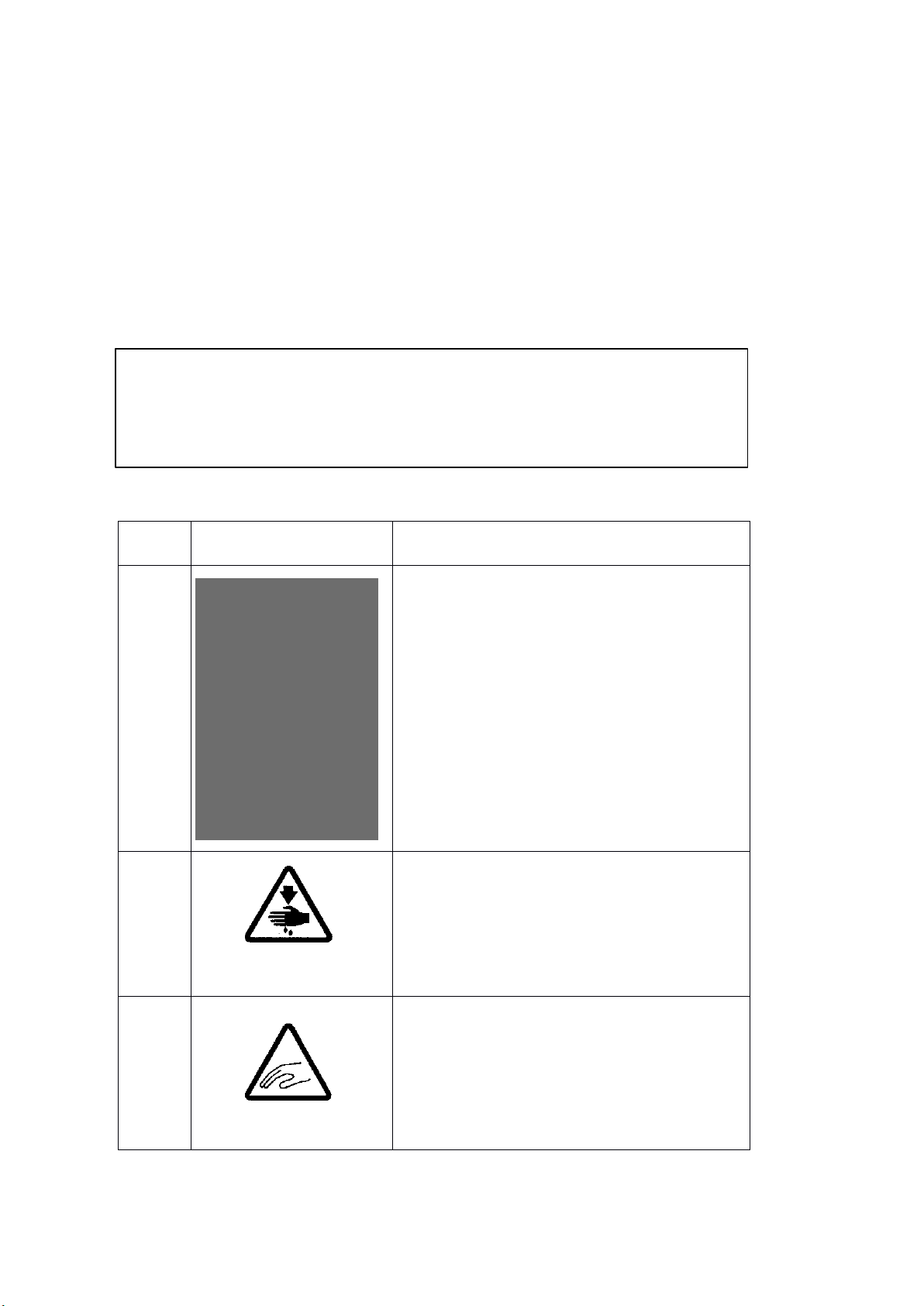
Warningsign
Meaningsofwarningsign
1
2
3
Cautionforsewingmachineoperation:
Warningtooperatethesewingmachine
withoutsafetyguardsandtoprohibitdoing
anyoperationexceptsewingwhilethe
poweristurnedon.
<Interpretationofsign>
·Donotoperatewithoutfingerguard,eye
guard,beltcoverandothersafetydevices
.
·Beforethreading,changingneedleand
bobbinclearing,oilingetc.switchoffmain
switch.
Cautionforawoundonthefingers:
Warningtoapossibledangertocausea
woundonthefingersunderthespecified
operation.
Cautionforthefingers:
Warningtoapossibledangertobecaught
thefingersinthemachineunderthe
specifiedoperation.
FOR
FOR
FORYOUR
Ifyouoperatethesewingmachinefirsttime,pleasemakesuretoreadthefollowing
instructionsforyoursafetyandproperoperation.
CAUTION
Inthistechnicalmanual。thenoticeCAUTION
attentionforthesafety.Pleasekeepitinmindwheneveryouworkwiththesewingmachine.
CAUTION
CAUTION
CAUTION
CAUTIONisusedasthenoticetowarnapossibledangertocauseawound
CAUTION
CAUTIONismentionedatsomeparagraphtoattractyour
YOUR
YO UR
YOURSAFETY!
SAF ETY!
SAFETY!
SAFETY!
Explanations
Explanations
Explanations
Explanationsfor
for
the
f or
th e
forthe
thewarning
war ning
warning
warningsigns
sig ns
signs
signs
Page 3

Caution
★ For avoiding the sewing machine from the troubles,please do not operate the sewing
machine under the following conditions.
1. T emperature and humidity
During operating:
The atmosphere temperature should not exceeded more 350 ℃( 9 5° F ) or less 5°C(41°F).
During transportation:
The atmosphere temperature should not exceeded more 55°C(131°F) or less -10°C(18°F).
The relative humidity in the atmosphere should not exceeded more 85%or less 45%.
2. Atmosphere for the machine operation
In the atmosphere filled with dust or corrosive gas.
In the atmosphere filled with flammable or explosive gas.
3. Power source voltage
In the place where the power fluctuation exceeds more or less 10%of the fixed power voltage.
In the place where the power source cannot supply enough voltage to keep the motor running.
4. Power source voltage
In the place where the power fluctuation exceeds more or less 10%of the fixed power voltage.
In the place where the power source cannot supply enough voltage to keep the motor running.
5. Noise
In the place near a high frequency transmitter or a high frequency welder.
In the place filled with strong electromagnetic radiation or magnetic field.
Page 4

----- CONTENTS -----
1 STRUCTURE OF THE SEWING MAC HI NE ............................................................................................... 1
2 SPECI FICATION ........................................................................................................................................... 2
3 INSTALLATION ............................................................................................................................................. 3
3-1 Installation of the control box ........................................................................................................................... 3
3-2 Installation of the power switch ........................................................................................................................ 3
3-3 Installation of the oil pan .................................................................................................................................. 3
3-4 Installation of the sewing machine head ........................................................................................................... 4
3-5 Installation of the spindle motor ....................................................................................................................... 4
3-6 Connection of the operation panel .................................................................................................................... 5
3-7 Connection of the electric cables ...................................................................................................................... 5
3-8 Installation of the thread stand .......................................................................................................................... 6
4 LUBRICATION ............................................................................................................................................... 7
4-1 Filling the oil tank ............................................................................................................................................ 7
4-2 Oiling ............................................................................................................................................................... 7
5 PROPER O PER ATION ................................................................................................................................... 7
5-1 Installation of the needle .................................................................................................................................. 7
5-2 Threading the upper thread ............................................................................................................................... 8
5-3 Winding the bobbin thread
5-4 Settling the bobbin ........................................................................................................................................... 9
5-5 Setting the bobbin case ................................................................................................................................... 10
6 PROPER SEWING ........................................................................................................................................ 10
6-1 Operation of the halt switch ........................................................................................................................... 10
6-2 The sewing operation ..................................................................................................................................... 11
6-3 Adjustment of the thread tension .................................................................................................................... 12
7 ST ANDARD ADJ USTMENT ....................................................................................................................... 13
7-1 Adjustment of the needle bar position ............................................................................................................ 13
7-2 Adjustment of the position between the needle and the shuttle hook .............................................................. 14
...............................................................................................................................
8
7-3 Adjustment of the clearance between the shuttle hook and the needle
7-
4 Adjustment of the clearance between the driver and the needle ...................................................................... 15
7-5 Adjustment of the thread guide ...................................................................................................................... 15
7-6 Adjustment of the presser foot ....................................................................................................................... 16
7-7 Adjustment of the wiper ................................................................................................................................. 19
7-8 Adjustment of the bobbin winder ................................................................................................................... 19
............................................................ 14
Page 5

7-9 Adjustment of the work holder ....................................................................................................................... 20
7-10 Adjustment of the trimmer cam follower ....................................................................................................... 20
7-11 Adjustment of the position for the movable knife point .................................................................................. 21
7-12 Adjustment of the fixed knife position ........................................................................................................... 21
7-13 Adjustment of the thread take up spring swing stroke .................................................................................... 22
7-14 Adjustment of the thread take up spring tension ............................................................................................. 22
7-15 Adjustment of the thread tail after the trimming ............................................................................................. 22
7-16 Cancellation of the trimming function ............................................................................................................ 22
7-17 Adjustment of the upper thread tension release .............................................................................................. 23
7-18 Adjustment of the mechanical home position ................................................................................................. 23
7-19 Adjustment of the X-Y table contact pressure ................................................................................................ 25
7-20 Adjustment of the X timing belt tension ......................................................................................................... 25
7-21 Adjustment of Y stepping motor position ....................................................................................................... 25
8 MAINTENANCE .......................................................................................................................................... 26
8-1 Cleaning ......................................................................................................................................................... 26
8-2 Disposing of oil waste .................................................................................................................................... 26
9 BAD SEWING CONDI TI O N&ITS CAUSE AND REM EDY .................................................................... 27
PARTS CATALOG
A. ARM BED &IT'S ACCESSORIES(一) .................................................................................................... 31
B. ARM BED &IT'S ACCESSORIES(二) .................................................................................................... 34
C. SEWING MECHANISM(一) ................................................................................................................... 37
D. SEWING MECHANIS M(二) ................................................................................................................... 40
E. X-Y TABLE MECHANISM(一) ............................................................................................................... 42
F. X-Y TABLE MECHANISM(二) ............................................................................................................... 44
G. CABLE COMPONENT & DETECT O R M EC HA NI S M ............................................................................... 46
H. WORK HOLDER MECH A NI SM ( AIR OPERATED) ................................................................................... 48
J. PRESSER FOOT MECHANI SM ................................................................................................................... 51
K. PRESSER BAR LIFTING ME CH ANISM ..................................................................................................... 53
L. THREAD TRIMMING MECHANI SM ......................................................................................................... 55
M. WIPER MECHANISM .................................................................................................................................. 58
N. OIL LUBRI CATION MECHANISM ............................................................................................................. 60
R. ACCESSORIES ............................................................................................................................................. 62
Page 6
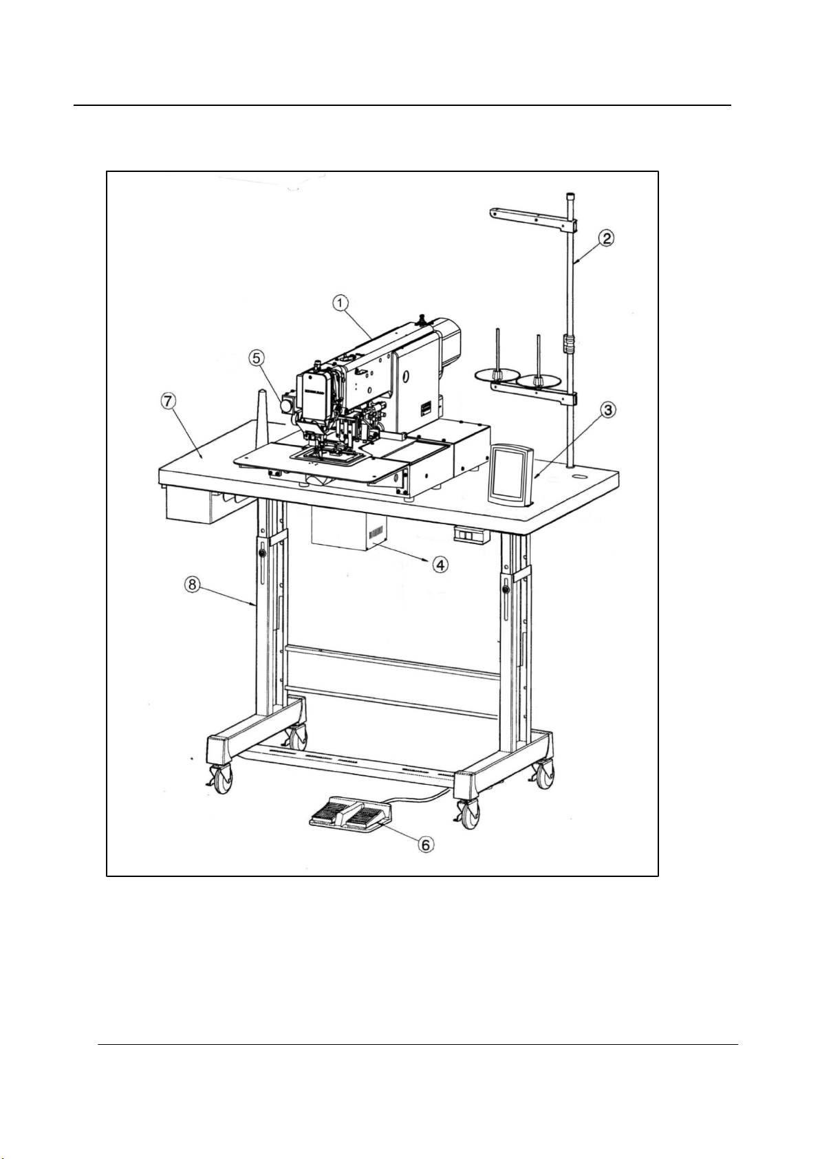
1 STRUCTURE OF THE SEWING MACHINE
HLK-1510 electronic pattern sewing machine is constructed with the following main parts
1 Sewing machine head ②T hread stand ③O peration P anel ④C ontrol U nit
○
⑤H a lt s w itc h ⑥W ork holder foot switch ⑦Wooden Table ⑧Steel stand
— 1 —
Page 7

2 SPECI FICATION
Sewing area: X-Direction(left/right) 100mm
Y-Direction(forward/backward) 100mm
Maximum sewing speed: 2500 rpm
Sewing speed: 10 steps variable from 200 to 2500 rpm
Stitch length: 0.1 to 12.7mm
Stitch type: Single needle lock stitch
Needle bar stroke : 41.2 mm
Thread take up lever stroke: 68mm
Class of needle: DP × 17#16(the standard specification)
Wiper system : Back to forward wiping system(the standard specification)
Presser foot lift: 15 mm(18mm max)
Presser foot stroke: Variable from 4mm to 10mm(4mm is standard)
Work holder lift: 25 mm
Hook: Large size shuttle hook
Bobbin case: With non racing spring
Bobbin: Large size aluminum bobbin
Thread trimmer system: Horizontal engagement with fixed knife and movable knife
Lubrication system: Manual oiling and replenishment with the oil braids from the oil tanks
Lubrication oil: White machining oil
X—Y drive system: Stepping motor and X-Direction timing belt drive
Y-Direction gear Intermittent or continuous feeding
Machine dimension: 1,200mm (W)× 740mm (L)×1,220mm (H)
main motor: 450W
— 2 —
Page 8

3 INSTALLATION
Caution
★ The machine should be installed by the specialists who have enough expe rience for the sewing machine
installations.
★ All the necessary electric wiring should be d one by electric engineers who are qualifi ed for the electric
wiring.
★ If any damage or fault is found on the machine at the installation,please do not operate until it is
repaired.
★ Please do not operate the sewing machine with excessive modifications from the standard specification.
3-1 Installation of the control box
If the control box is purchased without
assembling to th e table, the control box has
to be installed underneath the table. Please
install the control box with the in struc tion in
the paragraph
3-2 Installation of the power switch
If the power switch is purchased
without assembling to the table,the
power switch has to be attached with
the following procedure.
(1) Mount the power switch
2 underneath the table as shown on
screw
○
the figure.
(2) Fix the electric cords with the staples
underneath the table.
(3) Hook up the connector
switch
1 to the control box○7
○
1 with the wood
○
8 of the power
○
.
3
○
(4) Attach the power plug
Connect the foot switch
3-3 Installation of the oil pan
(1) Fix the oil pan
5 to another end of the power switch cord○4 . Connection of the foot switch
○
6 to the control box
○
1 at its four corners on the table top with four.
○
7 .The foot switch is enclosed in the accessory box.
○
— 3 —
Page 9
3-4 Installation of the sewing machine he ad
Caution
★ For the safety,please make sure to ca rr y the
sewing machine head by more than two
people.
(1) Make sure to hold the machine table
with the caster stopper.
(2) Fit the rubber cushion pads
each hole
rubber cushion pads are enclosed in the
accessory box.
(3) Put the sewing machine head on the
table top and set the each leg
each rubber cushion pad
(4) Attach two hinge s
machine bed .
(5) At this time,take notice that the E-shaped snap ring on the front side hinge must be come to the backside,
and E-shaped snap ring on the backside hinge must be come to the front.
(6) These parts are all enclosed in the accessory box.
(7) Fit the screw holes
through these holes and fasten the bolt
washers
(8) Fasten firmly hexagonal socket head set screws
hinges
(9) Insert the headrest
4 on the tabletop. The
○
6 temporarily,make the setting screw
○
9 of the hinges○6 to the bolt setting holes○8 ong the table top then,pass the bolt○10
○
12 and the nuts ○13
○
6
perfectly.
○
14 into the hole
○
3 into the
○
○5 to the
○3
.
10 to fix the hinges○6 with the flat washers○11 ,the spring
○
7 ,which se t the hi nges○6 temporar ily then,fix the
○
15 on the tabletop.
○
7 fastening on the left side surface of the
○
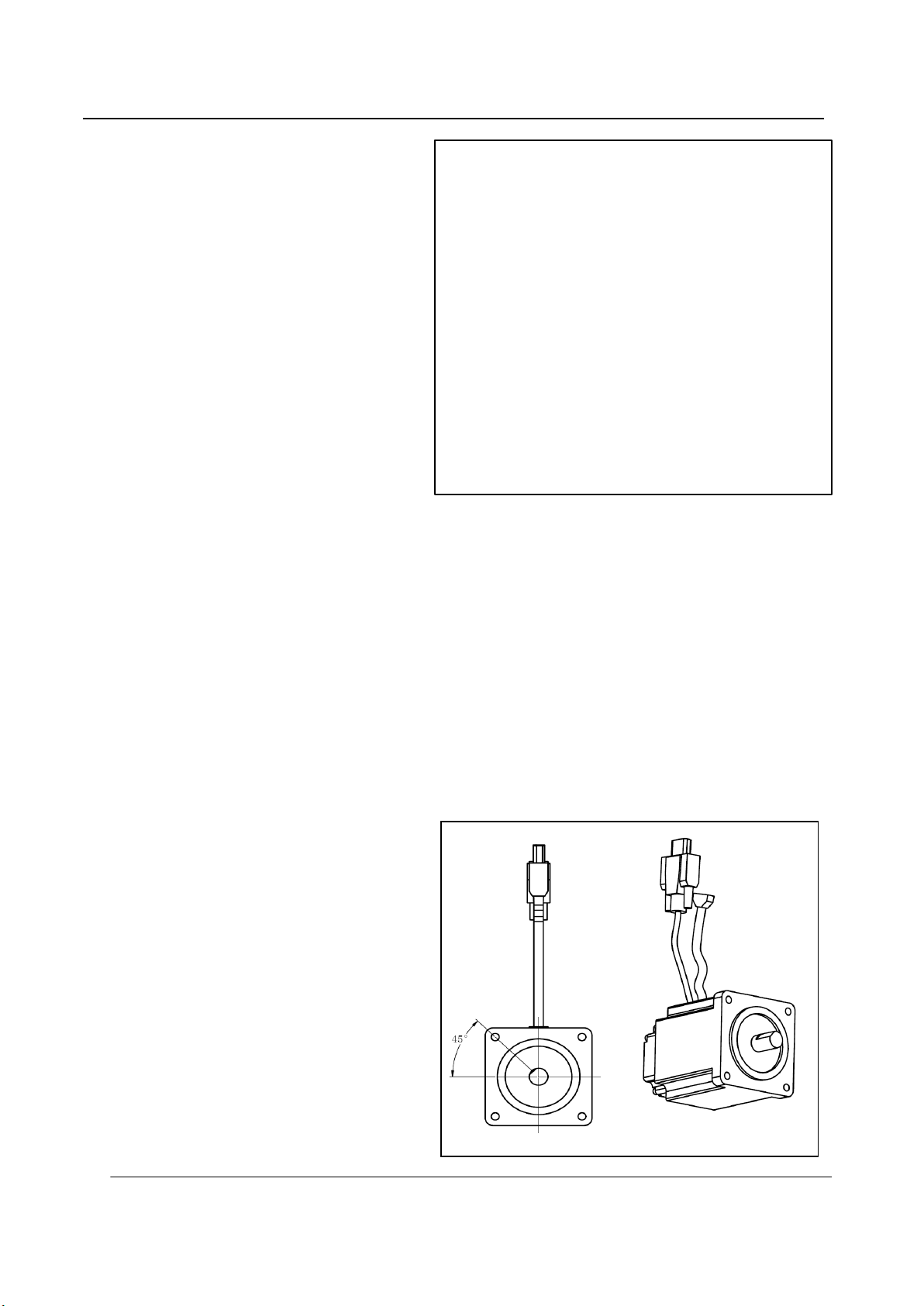
3-5 Install ati on of the spindle m ot or
If the spindle motor has been removed from
the machine for the adjustment or the like,
fix the spindle motor as the procedure
described right.
(1) Spindle motor according to right: put
the signal cord upward.
(2) Adjust the plane of the motor shaft
alignment of the left on the motor
mounting holes, 45 ° Angle adjustment.
— 4 —
Page 10

3-6 Connection of the operation panel
Please connect the operation panel with the instructions of operation panel manual enclosed in the packing.
3-7 Connection of the electric cables
Please make sure to
ground the place
where there is a
mark. Failure to do so
may cause electric
shock and/or
malfunction.
(1) Connect the machine head and the control
box with cables as shown on the figure.
(2) Hold the dangling cables under the table
with accessory tie holders and cord ties.
(3) At this time, please check whether the
cables are not pulled when tilting the
sewing machine.
(4) Control box back and socket as shown on
the below figure
(5) Printed circuit board wiring as shown on the top of next page
X4: Spindle motor power X5: Spindle motor signal X6: RS-232C(selection)
X7: Operation panel X8: Foot switch X9: Electromagnet output
X10:RS-232C(selection) X11: Control signal one X12: Expand I /0
X13: Control signal two X14: X spindle stepping motor X15: Y spindle stepping motor
G: Grounding wires
— 5 —
Page 11

3-8 Installation of the thr ea d st and
(1) Assemble the
thread stand with the
instructions enclosed in
the packing.
(2) Fit the thread
stand
1
in the thread
○
stand holeg on the
tabletop.
(3) Fix the thread
stand
○1 firmly from the
rear side of the table
with tightening the
nut
washers
4 and the
○
2 ,○3 .
○
— 6 —
Page 12

4 LUBRICATION
Caution
★Please make sure to turn power switch off before oiling.
★Please make sure to put some oil before starting the operation of the brand new machine or
NOTE : Please use high quality white machining oil.
4-1 Filling the oil tank
Pour the oil through the oil
hole
1 to the oil tank○2 on the
○
machine arm . Move the work
holder by hand to the right end
then,machine bed.Please Pour the
oil through the oil hole
oil tank,fill with the oil over level
mark
5 of the oil tank.
○
4-2 Oiling
Put some oil to red marked oil
holes(NO.
7 ~
○
10 ).
○
4 to the
○
5 PROPER OPERA TION
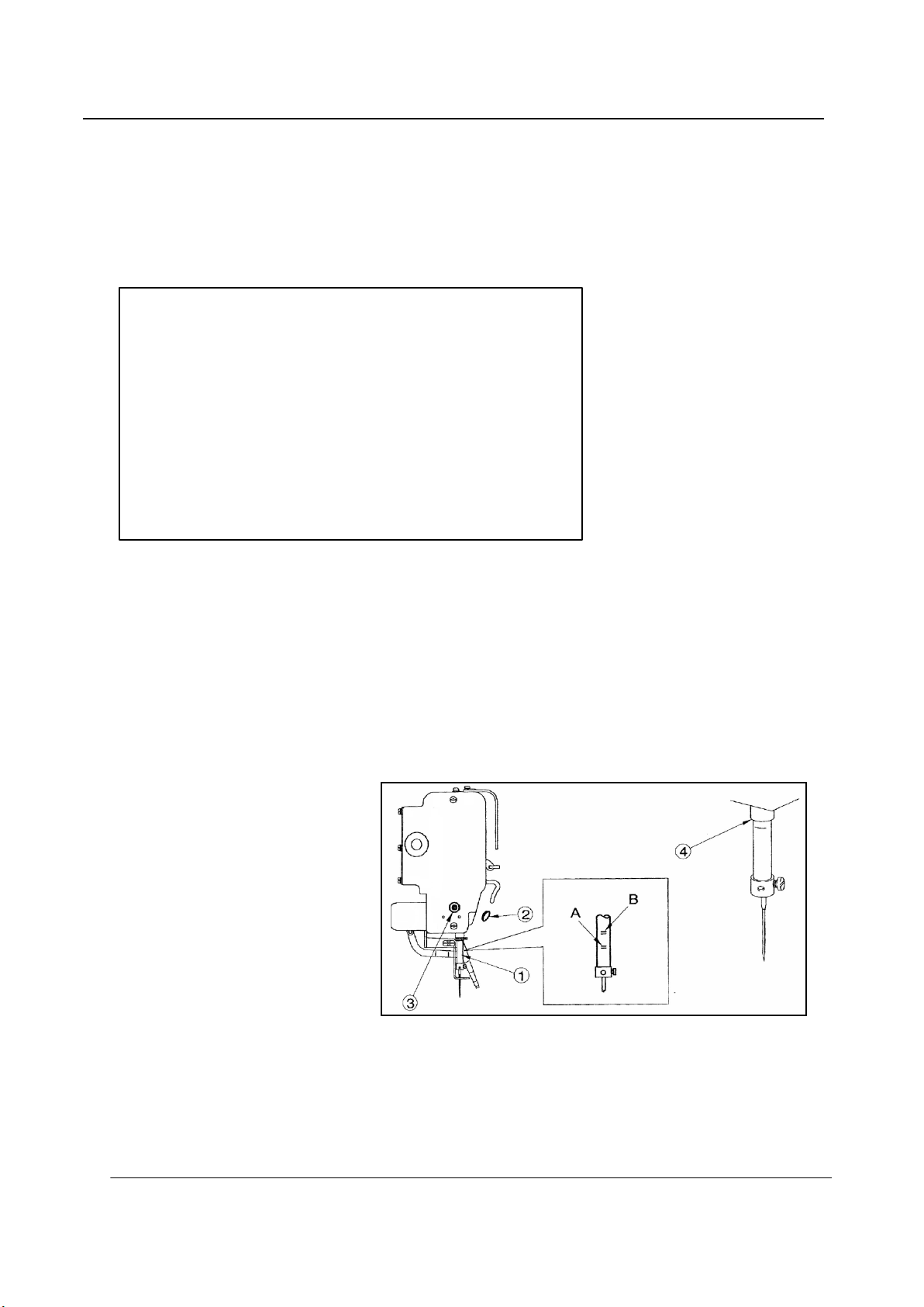
5-1 Installation of the needl e
Caution
★Please make sure to turn the power switch OFF before installing or replacing the needle.
★Please pay attention for the fingers not to be wounded by the needlepoint.
(1) Loosen the needle set screw
Insert the new needle
head is reached the end of the hole of the
3
needle bar
(2) Fasten the setting screw
the needle groove
○
.
2 until the needle
○
4 to the front
○
1 then,
○
1 with facing
○
— 7 —
Page 13

5-2 Threading the up per t hr e ad
★ Please make sure to turn the power switch off before threading the upper thread.
★ Please thread the upper thread with referring to the below figures.
5-3 Winding the bobbin thread
★Please make sure to pull the upper thread out of the needle before winding the bobbin thread
(1) Turn the power switch ON.
(2) Press the READY key on the
operation panel twice slowly. Firstly
Press, the work holder moves to home
position.Secondly, the interface for data
input will be shown.
(3) Press the SELECTION key on the
operation panel to select the
BOBBIN-WIND key , then press
the ENTER key ,at this time, work
holder goes down.
(4) Then , Wind mode window will be
appeared.(the background color is blue)
— 8 —
Page 14

(5) Pass through the thread from the thread
stand
4 as shown on the right figure .
○
then , wind the thread to the empty
bobbin
direction couple times and insert the
bobbin
(6) Push the adjust lever
“b” direction.
(7) Step on the gra y color star t foot switch
. The thread is kept winding to the
Bobbin
switch is stepping on.
(8) When the bobbin becomes full of the
thread,the adjust lever
the original position.
(9) Step the gray foot switc h to exit winding mode, and press the Escape key to back to the standard
operation interface.
(10) To wind the bobbin thread during the sewing operation,carry out above (2) to (7) procedure,then,the
5 in the arrow mark “a”
○
5 into the bobbin winder
○
7
in the arrow mark
○
5 while the gray color start
○
6
○
6 .
○
is returned to
○8
bobbin winding is performed automatically.
5-4 Settling the bobbi n
(1) Set the bobbin
(2) Pull the bobbin thread
thread through the thread hole
(3) At this time,pull the bobbin thread
the bobbin
not,set the bobbin
to get the proper rotation.
2 into the bobbin case
○
○
2 if it is rotaled to the arrow direction.if it is
○
2 into the bobbin case○1 over again
○
1 .
○
3 into the slit○4 and pass the
5
.
○
3 then,check with
○
— 9 —
Page 15

5-5 Setting the bobbin case
1
(1) Set the needle bar to its highest position then,open the cylinder cover
(2) Open the bobbin case latch lever
[NOTE]Please pull the bobbin thread about 2.5mm out of the thread hole(NO.4)of the bobbin case.
2 fully then,fit it securely in the inner hook
○
○
.
3 .
○
6 PROPER SEWING
6-1 Operation of the halt switch
If an incident such as a thread breakage,needle breakage and any other incidents are happened during the
sewing operation,please hit immediately the halt switch.The sewing machine running is stopped instantly.
Caution
★ B efore start the sew ing operation,please make sure the location of the halt switch and keep it in mind the
function and how to use it.
★ Please keep away the hands and the face from the needle during the sewing operation.
1
(1) Press the HALT switch
operations will stop,and the sewing
machine will stop at the needle UP state
without trimming the thread.
(2) Remove the cause of the abnormality.
(3) To continue sewing,turn the HALT
switch to the right. The switch will be
unlocked.Next,press the Escape key
○
, All
on the operation panel,then press
key to select the key or other
key. in the end ,press key,and
work holder will go up and return to the
— 10 —
Page 16

home position.
(4) When the start switch
Caution
★ Dependi ng on the shape of the work holder,the collision may be happened with the work holder and the
presser foot while the work holder is on the way back to the home position.For avoidance of this accident,
before starting the sewing operation . program the work hol der returning home with the operation panel of
the control box to trace the sewing pattern.
6-2 The sewing operation
Caution
★ It is very dangerous to operate the sewing machine without the safety guards(Eye guard:belt cover,Link cover,
Finger guard etc.).
★ Please make sure to always operate the sewing machine with the safety guards.
★ Please do not put unnecessary articles except for the sewing operation on the tabletop.
★ Please keep the hands and the face away from the needle.
(1) Turn the power switch○1
The collision may be happened with
the work holder and the presser foot
depending on the work holder shape
when the work holder is moved to
original position.
(2) In sewing interface, press to
return to the interface of data input.
(3) In the interface of data input, press to
2
(left)is pressed again,the operation will start .
○
ON.
select the ,then press to
enter the interface for selecting the
mode(as shown in the figure righe)
(4) After mode selecting end , back
to the inte rface of data input, pres s
to select ,then enter the the
interface for selecting pattern number ,
— 11 —
Page 17

(5) Back to the interface of data input,
press ,then enter the Sewing
Interface(the background color is blue)
(6) When the start switch
pressed,the work holder
down ,the operation will start .
For the deta ils ,please
refer to the
instructions on the
technical manual
[Operation Panel].
6-3 Adjustment of the thread tension
2 (left) is
○
3 will go
○
The thread tension between the upper and bosom thread should be balanced in the best condition.
When the upper thread tension is well balanced with the bobbin thread tension,both threads are interlocked
along the centerline of fabric layers as shown on the below figures.
NOTE Normally weaker bobbin thread tension brings better sewing quality.
So it is prefer to set bobbin thread tension first and then set upper thread tension.
(1) Bobbin thread tension
Adjust the bobbin thread tension with the thread tension adjusting screw
thread tension becomes loose if turn the thread tension adjusting screw
2 on the bobbin case○1 .The
○
2 to the counte r clockwise,and the
○
— 12 —
Page 18
thread tension becomes tight if turn it to the clockwise.
(2) Upper thread tension
Adjust the upper thread tension based on the bobbin thread tension.For this adjus tment,turn the thread
tension adjusting nut○3 .The upper tread tension becomes tight if turn the thread tension adjus ting nut
the clockwise,and the upper thread tension becomes loose if turns it to the counter clock wise.
3 to
○
7 ST ANDARD ADJUSTMENT
Caution
★Please make sure to turn the power switch OFF before adjust the sewing machine.
★If the adjustment is required under the power switch is ON,keep the start foot switch away from the foot.
★Be careful not to be wounded by the needle or the inner hook point.
★Please make sure to put the safety guards(Eye guard,Belt guard,Link cover and finger guard etc.)back on the
original location after the sewing machine adjustment.
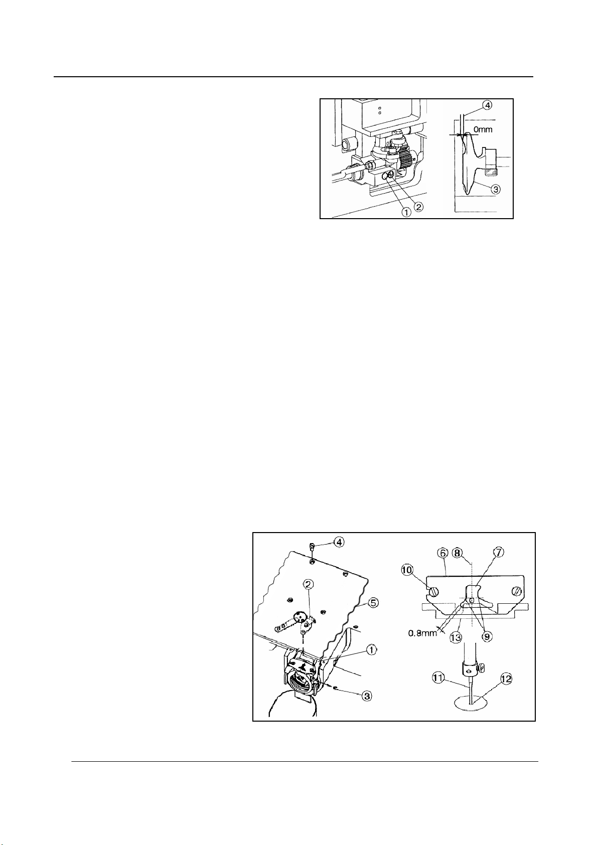
7-1 Adjustment of the needle bar position
(1) Turn the power switch OFF.
(2) Turn the sewing machine
pulley by hand then,stop the
1
3 .
○
4 .
○
○
at the lowest
2
○
○1 to the position where the needle ba r timing mark A is matched to the needle bar
4 then,tighten the needle bar holder setscrew ○3
○
— 13 —
.
needle bar
position.
(3) Remove the rubber plug
from the face plate then,
loosen the needle bar holder
setscrew
(4) Move the needle bar
bushing bottom line
NOTE: If the needle class is DP×5,match the needle bar timing mark B to the needle ba r bushing bottom
line
Page 19

7-2 Adjustment of the position between the needle and the shuttle hook
(1) Turn the power switch OFF.
(2) Turn the sewing machine pulley by
hand then,move up the needle bar
from the lowest position and stop it at
the position
timing mark C is matched to the needle
bar bushing bottom line.
NOTE:If the needle cla ss is DP×5,
match the ne edle bar timing mark D to
the needle bar bushing bottom line
(3) Open the cylinder cover
(4) Remove the bobbin case
(5) Turn the hook retainer lever
remove the hook retainer
(6) Loosen the driver setscrew
move the driver(No.10)and adjust the
shuttle hook point
with the center line
(7) After the adjustment,tighten the driver setscrew
2 where the needle bar
○
2
.
○
3
.
○
○
6 .
○
○9 then,
7 to be matched
○
8
of the needle.
○
1
○
2
○
5 then,
.
9 and put the bobbin case○4 ,the hook retainer○6 and
○
the hook retainer lever
7-3 Adjustment of the clearance between the shuttle hook and the needle
(1) Please take the same procedures as above paragraph 7-2.from(1) to(5).
(2) Loosen the outer hook setscrew
hook point and the needle becomes 0.05~0.1 mm.
(3) After the adjustment,securely tighten the outer hook setscrew
bobbin case back to the original location then,close the cylinder cover
5 back to the original location then close the cylinder cover○9
○
3 and turn the eccentric pin
○
4 so that the clearance between the shuttle
○
.
3 and put the hook retainer and the
○
5 .
○
— 14 —
Page 20
7-4 Adjustment of the clearance between the driver and the needle
(1) Please take the same procedures as above
paragraph 7-2.from(1)to(5).
(2) Please make sure the clearance between
the shuttle hook point and the needle has
been adjusted 0.05~0.1 mm at above
procedure 7-3 Adjustment of the
clearance between the shuttle hook and
the needle.
(3) Loosen the driver setscrew
and the needle
(4) After the adjustment,securely tighten the driver setscrew
back to the original location then,close the cylinder cover
7-5 Adjustment of the thread guide
(1) Remov e t h e E-shaped snap ring
the setscrews
(2) Loosen the setscrews
divides the needle groove
shoulder
hook retainer and the thread guide
it(standard clearance is 0. 8mm).If this clearance is too wide,it causes the trimming fai lure and if thi s
clearance is too narrow,it causes the sewing condition disturbance,the trimmed upper thread tail uneven
and the locking up the hook with the upper thread.
4 can become 0.
○
4 and remove the sliding plate(S) ○5
○
9 of the thread guide○6 .At this time,make sure that there is some clearance between the
○
1 and turn the eccentric pin○2 so that the clearance between the driver○3
○
3 which is engaging the movable knife○2 and the link ○1 then,loosen
○
10 and move the thread guide○6 to the pos ition where the needle center line○8
○
7 evenly and the rear side line ○9 of the needle is aligned with the
○
6 at least the upper thread can be passed smoothly through
○
○1 and put the hook retainer and the bobbin case
5 .
○
.
(3) After the adjustment,engage the
1 of th e trimmer mechanism
link
○
with the movable knife
the E shaped snap ring
the sliding plate(S)
original loca tion then,tighten the
setscrews
sliding plate(S)
needle
center
needle plate.
4 .At this time,set the
○
11 can come down to the
○
12 of the needle hole of the
○
○
5 back on the
○
5 so that the
○
2 with
○
3 and put
— 15 —
Page 21

7-6 Adjustment of the presser foot
[NOTE]The presser foot is a very important part to form the fine stitches.
It moves simultaneously with the needle and s tabilize the needle penetrating area of the sewing material with
pressing down it,when the needle sticks into or pulls out the sewing material and prevent the skip stitch or the
over penetration happening.Please adj us t th e pr e s se r foot properl y to the sewing ma te rials with the following
instructions.
7.6.1 Adjustment of the presser foot position
[NOTE]Please always adjust the presser foot position when the thickness of the sewing material is changed.
(1) Turn the power switch OFF.
(2) Remov e t h e face plat e○1 and the link cover
(3) Turn the sewing machine pulley by hand and stop the needle bar
make sure the se tscrew
shaft.This is the standard position of the eccentric cam
position , set it back to the standard position with the instructions on the paragraph[7-6-3.Adjustment of
the presser foot timing]in the following page.
(4) Turn the sewing machine pulley by hand and stop the needle at the highest position(this is also the thread
take up lever's highest posi tion).At this time,loosen the setscrew
8 and adjust the center line of the bell crank○6 to be parallel with the presser foot bar
shaft
○
(5) Insert the sewing material
stop the presser foot
(6) Loose n t h e p r es ser foot b ar s etscrew
position to be become the clearance bet ween the bot tom surface of the presser foot
the sewing material 0~0.5mm.At t he same time,rotate the presser foot ba r
come down to the center of the needle hole of the presser foot
5 of the eccentric cam○4 is positioned r ight beside the center line of the upper
○
10 under the work holder○11 and turn the sewing machine pulley by hand then,
○
12
at the lowest position.
○
14 and move the presser foot bar○7 then,adjust the presser foo○12
○
2 .
○
3 at the lowest position.At this time,
○
4 .If the eccentric cam○4
○
9 of the upper feed lock crank
○
○
12
.
○
is off from this
12 and the surface of
○
7 for the needle○15 to
7 .
○
(7) After the adjustment,put the face plate
[NOTE]The lower position of the presser foot,the more effective for the skip stitches. However,if the
presser foot becomes to Press the sewing material,the movement of the presser foot mechanism
generates a slight noise.And also,the presser foot stays longer to hold the sewing material,so
the upper thread tension becomes loose or the sewing pattern forming gets out of shape because
the presser foot catches the surface of the sewing material.For avoiding these troubles,please
lower the presser foot as small as possible.
1 and the link cover
○
— 16 —
2 back on the original location.
○
Page 22

[NOTE]If the thickness of the sewing material changes very often,it is recommended to takethe easy
way for the adjustment of the presser foot position with the method thatchange only the fixed
position of the presser foot after fixed the presser foot bar at higher position. For this
adjustment,loosen the setscrew
7.6.2 Adjustment of the presser foot lift during the sewing
[NOTE]The presser foot lift during the sewing can be adjusted 0 and 2~10mm.
(1) The presser foot lift during the sewing becomes 4~10mm at the condition which the connection of the
link
2 and the lever○3 with the shoulder screw○1
○
if the connection is made with A hole,and it becomes 0 mm if the connection is made with B hole.
(2) The stepping lift is adjusted 4mm when the sewing machine is shipped from the factory.
(3) For the adjus t ment at the each ran ge of the p re sser foot li ft,remov e the link cov er
move the adjust bolt
(4) If the link
presser foot position with adjusting the position of the presser foot bar or the presser foot itself with
loosing their setscrews
(5) Regarding the running noise and the vibration,the higher lift effects worse.So adjust the presser foot lift
2 connection is changed to A or B hole,the presser foot position is also changed.So reset the
○
5 .
○
○
6 or○7
.
16 then,move the presser foot
○
is as shown on the figure and it becomes 2 to 4 mm
12 up and down.
○
4 then,loosen and
○
during the sewing as small as possible.
(6) After the adjustment,put the link cover
4 and the face plate○8 back on the original location.
○
— 17 —
Page 23

7.6.3 Adjustment of the presser foot timing
[NOTE] The presser foot up and down movement during the sewing synchronizes with the needle up
and down movement. With changing this synchronized timing to the sewing materials,the skip
stitches can be prevented or the seam tightness can be improved.
For example,the delay of the presser foot timing against the needle movement prevents the skip
stitches especially to the thin materials,and the advance of the presser foot timing can improve
the seam tightness especially to the thick materials.
1
(1) Remove the link cover
(2) Loosen the setscrew “C” of the eccentric cam
(3) Turn the sewing machine pulley by hand and stop the needle bar
the setscrew “A” of the eccentric cam
is the standard position for the eccentric cam
(4) Loosen the setscrew “A” of the eccentric cam
(5) Hold the eccentric cam
machine pulley to the arrow direction “D”,the presser foot timing against the needle movement is
delayed,and if turn the pulley to the opposite direction,the timing of the presser foot is advanced.
.
○
2
.
○
3 at the lowest position.At this stage,
○
2 is positioned right beside the center line of the upper shaft.This
○
2
.
○
2
.
○
2
and turn the sewing machine pulley slowly by hand. If turn the sewing
○
(6) After the adjustment,tighten the setscrew “A” and “C” in turn with slightly pushing the eccentric
2
cam
(7) Put the link cover
to the arrow direction “E”.
○
1 back on the original location.
○
— 18 —
Page 24

7-7 Adjustment of the wiper
(1) Loosen the wiper setscrew
adjust the wiper
where the wiper
needle point
clearances right after the sewing
machine is stopped running at the
needle upper position (the thread take
up lever's highest position).
[NOTE] When the presser foot position or the presser foot lift is changed, the wiper
presser foot
function with operation
7-8 Adjustment of the bobbin winder
(1) Adjustment of the winding volume
Loosen the setscrew
4 .in that case , please do not use the wiper○1 .If do not use the wiper
○
1 to be positioned
○
1 passes under the
○
2 with about 2 mm
○
2 of the adjusting lever○1 and adjust the position of the adjusting lever○1 .If
○
3 and
○
1 may collide with the
○
1 ,cancel the wiper
○
move the adjus ting leve r
the adjusting lever
volume is adjusted 80%of the full volume when the sewing machine is shipped from the factory.
(2) Adjustment of the proper position of the bobbin winde r Firstly . loosen the setscrews
○
1 to th e arrow dire ction “a” the Winding volume is reduced,and if mov e
○
1
to the arrow direction “b”, the winding volume is increas ed .The winding
— 19 —
3 and○4 of
○
Page 25

the bobbin winder and put the empty bobbin○5 on the rotating shaft○6 then,push the adjusting
lever
1 to the arrow direction “a”.Secondary.move the whole bobbin winder to the arrow direction
○
“C” and stop it at the position where the empty bobbin is rotated then,tighten the setscrews
4
and
7-9 Adjustment of the work holder
If the sewing material is thick
and the work holder does not
press it strong enough,adjust
the work holder presser as
follow.
(1) Insert the sewing
material
work holder
(2) Turn the power switch
ON and lower the work
of the bobbin winder.This is the proper position of the bobbin winder.
○
1 under the
○
2 .
○
3
○
holder
holder foot switch
(3) Loosen the 2 of the setscrews
tighten the 2 of the setscrews
7-10 Adjustment of the trimmer cam follower
(1) Turn the power switch OFF and remove the top cover.
2
with the work
○
3 and move adjusting plate○4 unt il it touches the material○1 then,
○
3 .
○
— 20 —
Page 26

(2) Under the sewing machine regular stop condition(the needle stop position is upper and the take up lever
stop position is highest),loosen the setscrew
follower
about 1 mm clearance between the cam follower
tighten the setscrew
(3) Push the cam follower lever
engaged into the cam groove
(4) lf the cam follower
follower
the stopper screw
stopper screw
7-11 Adjustment of the position for the mova ble knife poi nt
(1) Tilt the sewing machine head to
the left to be able to see the
bottom component parts.
2 to be positioned to contact with the shoulder portion○3 of th e trimmer cam○1 with having
○
5 of the cam follower lever ○4
○
4 by hand to the arrow d i rec tio n an d ma ke sur e tha t th e c a m fol lower○2 is
○
3
smoothly.
○
2 is not engaged s moothly,under confirming with the condition which the cam
○
2 cont acts with the sho ulder port ion○3 of the tr immer cam ○1 , loosen the nut○7 and tighten
○
8 until it touche s with the stopper○9 of the ca m follower lever○4 then,loosen the
○
8 back about 1/3 turn and fix the nut
○
5 of the cam follower lever ○4 and adjust the cam
○
○
2 and the tri mmer cam○1 .After this adjustment,
.
7 firmly.
○
(2) Open the cylinder cover
(3) Check with the point
movable knife whether it is located
at the position apart 0.5mm fromthe front face of the hook retainer
(4) For the adjustment of the movable knife point
4
end
(5) After the adjustment,tighten the adjusting screw nut
7-12 Adjustment of the fixe d kni fe po siti o n
(1) Open the cylinder cover
(2) Remove the E-shaped snap
ring
movable knife
(3) Loosen the setscrews
remove the sliding plate
right and left then,adjust the position of the movable knife point.
○
4 , which engages the
○
○
1 of the
○
1
.
○
2 and the link○3
5 then,
○
6 .
○
.
2 .
○
1 ,loosen the adjusting screw○3 and move the rod
○
3
securely.
○
(4) Turn the sliding plate
position to be positioned for the blade edge
6 upside down and loosen two setscrews○9 then,adjust the fixed knife○10
○
7 to have the clearance 0.5m m from the edge of the needle
○
— 21 —
Page 27

plate○8
(5) After the adjustment,tighten the setscrews
(6) Put all the parts for this adjustment back to the original locations.
7-13 Adjustment of the t hread take up sprin g s wi ng s t roke
Loosen the setscre w
swing stroke to be become 9 to 10mm.
After the adjustment,tighten the setscrew
7-14 Adjustment of the thread t a ke up sprin g tension
Insert the screw driver
slit
○
regulator
up spring
driver to the clockwise,the thread take
.
2 and turn the whole thread tension regulator○3 then,adjust the thread take up spring
○
2
○
5 into the
○
4 of the thread tension
3 and adjust the thread take
○
1 tension.If turn the screw
○
9
○
securely.
securely.
up spring tension becomes tight.and if
turn the screw driver to the counter
clockwise.the thread take up spring
tension becomes loose.
7-15 Adjustment of the thread tail after the trimming
Adjust the thread tail
needle after the trimming with
turning the nut
pre-tension
If turn the nut
the thread tail becomes shorter
and if turn the nut
counter-clockwise,the tread tail
becomes longer.
1 .
○
2 to the clockwise,
○
3 from the
○
2 of the
○
2
to the
○
7-16 Cancellation of the trimming function
If the automatic trimming is not required during the sewing operation ,cancel the Trimming function with the
setting panel of the control box .
— 22 —
Page 28

7-17 Adjustment of the upper thread te nsi on r el ea se
[NOTE] (a) The upper thread tension release works when the upper thread is trimmed automatically or the
presser foot is lifted during the work holder feeding.
(b) If the upper thread tension release does not work properly when the upper thread is t rimmed
automatica lly, the thread tail fr om the needle becomes shorter then, it induces the ski p stitch
happening or pulling the thread tail out of the needle at the start of the sewing.
(c) During the sewing operation, the discs
presser foot is moving up and down.
If the discs
loose and the proper stitch condition can not be obtained.
(d) When the upper thread tension release is activated, the discs
regulator opens 0.8~1.0mm. This is the normal conduction of the discs
adjustment, take the following procedure.
1 of the thread tension regulator is not closed, the upper thread tension becomes
○
1 of the thread tension regulator is closed while the
○
1 the upper thread tension
○
1 opening. For this
○
(1) Remove the top motor cover.
(2) Fully turn the crank
(3) adjust the upper thread tension release for the di scs to be opened 0.8 to 1.0 mm. For this adjustment,
loosen the nut A then,if tighten the nut B,the discs opening becomes wider and if loosen the nut B,it
becomes narrower.
(4) lf the normal opening of the discs can not be obtained with the nut adjustment,loosen the wire fix
screws
(5) The wire
thread tension release again.
7-18 Adjustment of the mechanical home pos iti on
[NOTE]The mechanical home position is fixed at the center of the sewing area when the sewing machine is
shipped from the factory.However,it can be moved within the area covered with diagonal lines.
5 and adjust the tension of the wire
○
6
may be got longer over a long period machine operation.At that time, adjust the upper
○
3 of the rotary solenoid
○
2 in the arrow direction.At this time,
○
6 .
○
— 23 —
Page 29

(1) Turn the power switch ON and cancel the sewing area limit with the operation panel.
(2) After the cancellation of the sewing area limit, once. Turn the power switch OFF.
7-18-1. Shifting the mechanical home position to the X direction
(1) Remov e t h e X-Y cover (right),(left) and X cover.
(2) Loosen the detector plate fix screws(2 pieces)
mechanical home position is shifted to the left and if it is moved to the left, the mechanical home
position is shifted to the right.
(3) After the mechanical home position setting,tighten the detector plate fix screws
[NOTE] When the original mechanical home position is shifted.Please check the clearance between the X detector
plate and the X detector.This clearance should be set within the range of 1.0—1.5 mm.
1 . if move the detector plate
○
2 to the right, the
○
1
securely.
○
— 24 —
Page 30

7-18-2.Shifting the mechanical home position to the Y dir ection
(1) Loosen the Y-detector setscrew○5
4
(2) lf move the Y-detector
moved to the backward.the mechanical home position is shifted to the front.
(3) After the mechanical home position setting,tighten the screw
7-19 Adjustment of the X-Y table contact pr e ssure
[NOTE] When take the X -Y table apart or the X-Y table became weak in the joint s,adjust the X-Y table contact
pressure.The adjustment should be made the X-Y t able movement as smooth as possible without having
play.If the X·Y table cont ac t pres sure is too tigh t ,the over pressure induces the out of control on the
X-Y table movement.
(1) Remove the right and left X-Y cover and the right X cover plate.
(2) Loosen the setscrew(2 pieces)
(3) If tight en the both right and left contact presser adj usting screws
increased.
to the front,the mechanical home posi tion is shifted to the backward.If it is
○
.
2 so that the X fixed race
○
5
securely.
○
1 can be moved slightly.
○
3
,the X table contact pressure is
○
(4) Loosen the setscrews(2 pieces)
(5) If tighten the contact pressure adjusting screws
(6) After adjustment,tighten the setscrews
7-20 Adjustment of the X timing belt tensi on
[NOTE] The proper condition of the X
timing belt tens ion is standing that
they will not be got any yield even
it is slightly pushed by hand.
(1) Remove the right X cover and the
right X cover plate.
(2) Loosen the nut○8 and the
setscrew
(3) If the tighten the tension adjust screw
(4) After adjustment,tighten the nut
9 of the bracket○7
○
5 so that the Y fixed race
○
.
8 and the setscrew
○
4 can be moved slightly.
○
6
,the Y table contact pressure is increased.
○
2 and
○
10
,the X timing belt tension will be increased.
○
5 securely.
○
9 .
○
7-21 Adjustment of Y stepping motor position
(1) Remov e t h e motor cov e r.
— 25 —
Page 31

(2) Loosen four setscrews ○1 of the
Y-stepping motor adapter
(3) Press the Y-motor adapter
direction lightly.
(4) Fasten the sets crews
the motor cover to original position.
NOTE After the adjustment, please make sure
that there is no gap in the gear
mechanism. Please grease gear
periodically for reduction of noise or
abrasion
2 .
○
2
to arrow
○
securely, and put
1
○
8 MAINTENANCE
Caution
★Please make sure to turn the power switch always OFF when clean up the sewing machine.
★Before or after the sewing operation,clean up the sewing machine and check the Oil level in the oil tank.
8-1 Cleaning
(1) Turn the power switch OFF.
(2) Remove the dust and the
thread waste sticking
around the threading parts or
the shuttle hook area.
(3) Check the oil level in the
oil tank.1f the oil is under
the red mark level supply the
oil to be over the red mark
level.
8-2 Disposing of oil waste
7. lf the waste oil is full, please remove the oil .
— 26 —
Page 32

1.
2.
Adjust thread take up spring’s swing
Adjust fixed knife and needle plate
9 BAD SEWING CONDITION&ITS CAUSE AND REM EDY
[NOTE]Please fix the troubles during the sewing machine operation with referring to the following
instructions.Beside,if the trouble conditions are not coming under these classification,please contact the
sewing machine dealers nearby.
Bad
condition
Upper thread
breakage after
happens
Upper thread is
pilled out from
needle
Cause Remedy Ref. page &
item
Poor thread tension Use better quality thread —
Tight upper thread tension Adjust thread tension 6-3
Strong thread take up spring Adjust thread take up spring properly 7-14
Upper thread is thicker than
needle size
Damages on shuttle hook or
drive
Damages inside presser foot
needle hole
Needle touches with presser
foot needle hole
Needle and shuttle hook are
not in proper timing
Thread melts with needle heat Slow down sewing speed —
Thread tension discs are not
opened at trimming
Thread take up spring swings
too much
Upper thread is broken before
regular trimming
Needle size is bigger than
thread size
Pre–tension is too tig ht Adjust pre-tension 7-16
Thread guide is in wrong
position
Needle and shuttle hook are
in bad timing
Trimmer timing is not correct Adjust trimmer cam position 7-10
Change needle to suitable size —
Change them new ones or gr ind them with
buffing wheel or grind stone
Change it new one or grind it with buffing
wheel
Move presser foot position 7-6-1(6)
Adjust the timing 7-2
Use silicon oil —
Use needle cooler —
Adjust thread tension release 7-17
stroke
position
Change needle to suitable size
Adjust thread guide position properly 7-5
Adjust the timing properly 7-2
Adjust movable knife position 7-11
Adjust synchronizer position —
—
—
7-14
7-12
— 27 —
Page 33

3.
4.
5.
6.
Bad
condition
Skip stitch
happens at
start sewing
Thread tail
from needle is
too long after
trimming
Trimming is
not functioned
Skip stitching
often happens
Cause Remedy Ref. page &
item
Too short bobbin thread by
Use non racing spring with bobbin
—
bobbin spinning after
trimming
Bobbin thread tension is too
Loosen bobbin thread tension spring 6-3
tight
Thread tail from needle is
very short after tr im m in g
Decrease pre-tension 7-16
Adjust trimmer cam position 7-10
Adjust synchronizer position
—
Make thread take up swing stroke smaller 7-13
Advance thread tension release timing Control unit
Adjust thread guide position properly 7-5
Pre-tension is too loose Make pre-tension tighter 7-14
Trimmer timing is delayed Adjust trimmer cam position 7-10
—
Upper thread tension release
Adjust synchronizer position
Delay tension release timing Control unit
timing is too fast
Tread guide is in wrong
Adjust thread guide position properly 7-5
position
Trimmer function is canceled Resume trimmer function Control unit
Fixed knife is dull Change it new knife 7-11
Movable Knife is in wrong
Adjust movable knife position properly 7-11
position
Skip stitching happens at
Fix skip stitching
7-6
trimming
Trimmer timing is wrong Adjust trimmer cam position
Adjust synchronizer position
Needle and shuttle hook
clearance is too big
Needle and shuttle hook
timing is not correct
Adjust needle and shuttle hook timing
properly
Adjust needle and shuttle hook timing
properly
Needle is bent Change it new needle
Needle is bent by driver Adjust needle and diver clearance
7-10
—
7-2
7-2
—
7-4
properly
Needle is in wrong position Amend needle position 7-2
Presser foot position is not
Adjust presser foot position properly 7-6
correct
— 28 —
Page 34

7.
8.
9.
10.
11.
Bad
Cause Remedy Ref.page &
condition
Upper thread tension is not
tight enough
Thread tension regulator’s
discs are opened during
sewing
Stitch forming
is loose
Presser foot position is not
correct
Driver and shuttle hook
clearance is very small
Presser foot up and down
timing is not proper
Cables wiring is
Sewing
machine does
not work even
start switch is
turned ON
disconnected
System softwa re is no t
loaded
Emergency stop switch is
kept ON
Synchronizer cable is
Sewing
machine runs
disconnected
Synchronizer is out of order Change it new synchronizer
idle at high
speed when
power switch is
turned ON
Work holder activate cable
is disconnected
Work holder
does not work
Work holder activate cable
is not strong enough
Work holder switch is out of
order
Work holder switch is not
strong enough
Sewing pattern
is distorted
sewing material weight is
very heavy
X timing belt is loose Adjust X timing belt tension properly 7-21
item
Increase upper thread tension 6-3
Adjust tension regulator position
7-17
properly
Adjust upper tension release position
7-17
properly
Adjust presser foot position properly 7-6
Change shuttle hook
—
Adjust presser foot timing properly 7-6
Connect all cables precisely 3
Load system software to control box 5-1
Release emergency stop switch lock 6-1
Connect synchronizer cable precisely control unit
—
Connect the cable precisely control unit
Increase work holder pressure 7-9
Change it new work holder switch
—
Increase work holder pressure 7-9
Slow down sewing speed 6-2
Slow down feeding speed control unit
Select sewing material weight level at
control unit
feeding
— 29 —
Page 35

12.
Y detectors cable are
Y detectors cable are
Detector and detector
13.
Detector and detector
Detector and detector
plate clearance is bigger
Bad
condition
Work holder does
no stop at home
position
Work holder
stops at not
original home
position
Cause Remedy Ref. page & item
X-
Connect X-Y cables precisely
—
disconnected
X-
Change them new detectors
—
out of order
Adjust the clearance properly 7-19
plate clearance is too big
Check setscrews and tighten them
plate mounting is loose
than standard
securely
Adjust detector and detector plate
clearance properly
7-19
7-19
— 30 —
Page 36

A.ARM BED &IT'S ACCESSORIES(一)
— 31 —
Page 37

Fig.
A.ARM BED &IT'S ACCESSORIES(一)
No.
A01 HK41B88001 Type plate 1
A02 H924025050 Pin 2 Ф2.5×5
A03 HK42C58001 Motor cover 1
A04 HK41B98001 Plate 1
A05 H6642B8001 Screw 4 M4×8
A06 HM019B8001 Arm plate 1
A07 HA307B0674 Rubber plug 1
A08 HM015B8001 Bracket 1
A09 HA104G0654 Screw 4 1/8(44)×6
A10 H6671B8001 Hinge 2
A11 HA100C2190 Screw 2 11/64(40)×8
A12 HM014B8001 Plate 1
A13 H6675B8001 Plate 1
A14 HA106B0676 Screw 2 9/64(40)×6
A15 HZ11040250 Screw 1 M4×25
A16 H6609I8001 Screw 1 M4×20
A17 H6642B8001 Screw 5 M4×8
A18 H6648I8001 Nylon clip 5 AB-6N
A19 HK42B48001 Bed cover 1
A20 HK42B68001 Middle cover 2
A21 H415030120 Screw 10 M3×12
A23 HK42B88001 Front guide 2
A24 HK43B08001 Back guide 2
A25 H6698B8001 Screw 2 M3×6
A26 HK43B27101 Cylinder cover 1
A26 H663FB7101 Cylinder cover 1
A27 H6692B8001 Screw 2 9/64(40)×3.2
A28 H6691B8001 Spring 1
A29 H431050080 Screw 1
A30 H661EB8001 Screw 3 M4×6
A31 HA106B0675 Thread guide 1
A32 H3000B2130 Thread guide 1
A33 H415040080 Screw 2 M4×8
A34 HK44B88001 Plate 1
A35 HA600B2050 Thread guide 1
A36 HA700B2050 Thread guide 1
A37 H4715B8001 Rubber 5
A38 H431040060 Screw 1 M4×6
A39 H6689B8001 Thread take-up lever guard 1
A40 H6642B8001 Screw 1 M4×8
A41 HA307B0673 Rubber plug 1
A42 HK44B68001 Bed cover 1
A43 H6642B8001 Screw 4 M4×8
Part No. Description Pcs. Remarks
M5×8
— 32 —
Page 38

Fig.
A.ARM BED &IT'S ACCESSORIES(一)
No.
A44 H6665B8001 Screw 2 M4×30
A45 H6664B8001 Ball bushing 2
A46 H415050180 Screw 4 M5×18
A47 HK42B58001 Cover 1
A49 HK45B18001 Cover 1
A50 H661EB8001 Screw 2 M4×6
A51 H6613I7102 Connector panel 1
A52 H6642B8001 Screw 8 M4×8
A53 HK44B38001 Cover 1
Part No. Description Pcs. Remarks
— 33 —
Page 39

B. ARM BED &IT'S ACCESSORIES(二)
18
4
1~
------,
::
~
1
9
~
44
~
22
— 34 —
Page 40

Fig.
B.ARM BED &IT'S ACCESSORIES(二)
No.
B01 HA115B0709 Pin 1
B02 HA115B0708 Screw 1
B03 HA310B0703 Regulator casing 1
B04 HA115B0701 Screw 1
B05 HA115B0706 Thread take-up spring 1
B06 HA310B0705 Thread tension discs 2
B07 HA310B0702 Disc retaining plate 1
B08 H6675C8001 Thread tension spring 1
B09 HA115B7010 Thumb nut revolution stopper 1
B10 HA310B0701 Thumb nut 1
B11 H660GB8001 Thumb nut 1
B12 H660FB8001 Spring guide 1
B13 H660EB8001 Thread tension spring 1
B14 H660HB8001 Thread tension stud 1
B15 H6662B8001 Thread guide 1
B16 H6663B8001 Spacer 1
B17 HK45B08001 Top cover 1
B18 H6656B8001 Spacer 1
B19 H6651B8001 Lever 1
B20 H6648B8001 Driven shaft 1
B21 H431030040 Screw M3×4 2 M3×4
B22 H6649B8001 shaft 1
B23 H6682D8001 Screw M4×10 2 M4×10
B24 H431040040 Screw M4×4 2 M4×4
B25 H6645B7101 Lever 1
B26 H6650B8001 Pin 1
B27 H6657B8001 Wheel 1
B28 H6644B8001 Bracket 1
B29 H4921K8001 Pin φ2.5×8 1
B30 H6652B8001 Cam 1
B31 H4917K8001 Pin φ2.5×12 2
B32 H6653B8001 Spring 1
B33 H6655B8001 Pin φ5×56 1
B34 H6658B8001 Tire 1
B35 HA710B0674 Thread guide 1
B36 HA710B0673 Thread tension stud 1
B37 HA112B0693 Thread tension discs 2
B38 HA710B0672 Thread tension spring 1
B39 HA710B0671 Thumb nut 1
B40 H662EB8001 Plate 1
B41 H3200B2100 Screw 1 9/64(40)×6.5
B42 HA100H2150 Screw 1 9/64(40)×11
B43 H662IB8001 Spacer 1
Part No. Description Pcs. Remarks
— 35 —
Page 41

Fig.
B.ARM BED &IT'S ACCESSORIES(二)
No.
B44 HE121B8001 Spacer 1
B45 H6756B8001 Knife 1
B46 H6698B8001 Screw 2 M3×6
B47 HA310B0705 Thread tension discs 2
Part No. Description Pcs. Remarks
— 36 —
Page 42

C. SEWING MECHANISM(一)
40
50
45
~
""
37
\
38
11
~
4
43
58
13 14
26
19
~~~\\
25
0
C)
0
17
~0
29
'
— 37 —
27
Page 43

Fig.
C. SEWING MECHANISM(一)
No.
C01 H2009B0743 Felt 3
C02 H2009B0742 Felt 1
C03 H6616B8001 Felt 1
C04 H6617B8001 Bushing 1
C05 H2009B0731 Felt 1
C06 H6616B8001 Felt 1
C07 H6620B8001 Bushing 1
C08 H431050100 Screw 1 M5×10
C09 H3208H0661 Ball bearing 1
C10 H3416D0692 Screw 2 15/64(28)×8
C11 H6612B8001 Needle bar bushing(upper) 1
C12 H6613B8001 Needle bar bushing(lower) 1
C13 HK40C58001 Drive shaft 1
C14 H6607C8001 Crank 1
C15 HA105D0662 Screw 1 1/4(40)×4
C16 HA307C0662 Screw 2 1/4(40)×6
C17 HA100C2070 Screw 1 9/32(28)
C18 H6612C7101 Thread take-up lever assy 1
C19 H6613C8001 shaft 1
C20 H6614C8001 Crank 1
C21 H2004H0067 Screw 1
C22 H6616C8001 Crank 1
C23 HA104C0658 Needle bar joint 1
C24 HA104C0659 Screw 1
C25 H6619C8001 Crank 1
C26 H431050120 Screw 1 M5×12
C27 HM005C7101 Guide bracket assy 1
C28 H6623C8001 Screw 2 M4×8
C29 HA100C2200 Square block 1
C30
C31 HA300C2070 Thread guide 1
C32 H6625C8001 Thread guide 1
C33 HA100C2170 Screw 1 1/8(44)×4.5
C34 HM010C8001 needle 1 DP×17-18
C35 HA108G0661 Collar 1
C36 HA105D0662 Screw 2 1/4(40)×4
C37 H6608C8001 Pulley 1
C38 H431040060 Screw 2 M4×6
C39 HK42C38001 Main shaft motor 1
C40 H415050140 Screw 4 M5×14
C41 H8827O8001 Coupling 1
C42 H415030120 Screw 2 M3×12
C43 HA113D2112 Gear 1
Part No. Description Pcs. Remarks
H6624C8001 Needle bar 1
— 38 —
Page 44

Fig.
C. SEWING MECHANISM(一)
No.
C44 HA108C0663 Screw 2 SM1/4(40)×7
C45 HK42C98001 Hand wheel 1
C46 H609030120 Pin 1
C47 HK43C18001 Shaft 1
C48 H4767E8001 Spring 1
C49 HK43C08001 Bushing 1
C50 H5311F8001 Screw 1 11/64(40)×6.1
C51 H415030100 Screw 1 M3×10
C52 HF15401014 Bearing 1
C53 HF15401012 Washer 1
C54 HA108C0662 Screw 2 1/4(40)×5
C55 HA113D2122 Gear 1
C56 H431050080 Screw 1 M5×8
C57 H3205J0661 Bushing 1
C58 H6606F8001 Thread trimmer cam 1
C59 HA105D0662 Screw 2 1/4(40)×4
Part No. Description Pcs. Remarks
— 39 —
Page 45

D. SEWING MECHANISM(二)
4
6\
5~
16
17
18
19
22
23\
24
~
~~
~36
r \
30
31
28
~
32
29
35
37
— 40 —
Page 46

Fig.
D. SEWING MECHANISM(二)
No.
D01 HA304G0656 Screw 2 3/16(28)×15
D02 H6634C8001 Felt 1
D03 H6628C7101 Connecting rod assy 1
D04 H6628B8001 Bushing 1
D05 H2010J0066 Nut 1 9/32(28)
D06 H431050050 Screw 1
D07 H6630C8001 Screw 1 9/32(28)
D08 H6635C8001 Rock shaft 1
D09 H431050080 Screw 1 M5×8
D10 H6670C8001 Collor 1
D11 HA305E0662 Screw 2 SM15/64(28)×4.5
D12 H6631C8001 Sector gear 1
D13 H6627B8001 Oil braid 1
D14 H2009B0743 Felt 2
D15 H431060100 Screw 2
D16 H6684C8001 Bobbin case 1
D17 H6685C8001 Bobbin 1
D18 H6674C8001 Hook retaine 1
D19 H6683C8001 Inner hook 1
D20 H6654C8001 Hook driver 1
D21 H415050160 Bolt M5×16 1 M5×16
D22 H6646C8001 Hook clamp 2
D23 H6658C8001 Screw 2 1/8(40)×4
D24 H6657C8001 Thread guide 1
D25 H431060120 Screw 1 M6×12
D26 HC01048019 O ring 1
D27 H6648C8001 Eccentric shaft 1
D28 H6625B8001 Bushing 1
D29 HK44C87101 Hook shaft assy 1
D30 H6642C8001 Outer hook 1
D31 H6648C8001 Eccentric shaft 1
D32 H431060120 Screw 1 M6×12
D33 H6651C8001 Pin 1
D34 H6643C8001 Screw 2 1/8(44)×4.5
D35 H6644C8001 Washer 2
D36 H6645C8001 Spring 2
D37 HC01048019 O ring 1
Part No. Description Pcs. Remarks
— 41 —
Page 47

E. X-Y TABLE MECHANISM(一)
9
24~
21
20
28
— 42 —
Page 48

Fig.
E.X-Y TABLE MECHANISM(一)
No.
E01 HK42D38001 Cover 1
E02 HA70264C06 Screw 4 9/64(40)×8
E03 H7351C8001 Washer 4
E04 H415040080 Screw 2 M4×8
E05 HK42D18001 Cover 1
E06 HK42D08001 Screw 2 M3×6
E07 HK41D78001 Rear stopper Y 1
E08 HK42D48001 Cover 1
E09 H103040080 Bolt 6 M4×8
E10 H431030060 Screw 1 M3×6
E11 H416040100 Screw 4 M4×10
E12 HK41D18001 Fixed race Y 2
E13 HK41D08001 Retainer Y 2
E14 H6618D8001 Ball 80
E15 HK41D58001 Movable race Y 1
E16 HK41D38001 Front stopper Y 1
E17 HK41D98001 Connceting plate 1
E18 HA70264C06 Screw 2 9/64(40)×8
E19 H6623D8001 Cover 1
E20 HK40D68001 Movable race X 2
E21 H416040160 Screw 8 M4×16
E22 HK40D98001 Fixed race X 2
E23 H6610D8001 Stopper 2
E24 H6611D8001 Stopper 2
E25 H415040140 Screw 2 M4×14
E26 H415040400 Screw 2 M4×40
E27 H003002040 Nut 2 M4
E28 HK40D88001 Retainer X 2
Part No. Description Pcs. Remarks
— 43 —
Page 49

F.X - Y TABLE MECHANISM ( 二 )
— 44 —
13
·
~
27
32
33
~
Page 50

Fig.
F.X-Y TABLE MECHANISM(二)
No.
F01 H415050100 Screw 4 M5×10
F02 H6686D8001 Washer 4
F03 H6646D8001 Motor mounting plate Y 1
F04 H6632D8001 Screw 2 M4×6
F05 H6631D8001 Gear 1
F06 HK43D08001 Stepping motor 1
F06 HK43D08001 Stepping motor 1
F07 H415040120 Screw 4 M4×12
F08 HK46D68001 Rack Y 1
F09 H415050160 Screw 2
F10 H6649D8001 Rack adapter Y 1
F11 H6623B8001 Ball bushing 10 2
F12 H6693D8001 Screw 2 M4×14
F13 HK47E18001 Linear shaft Y 1
F14 HK41B58001 Bearing 2
F15 HK44D68001 Driving pulley B 1
F16 H6632D8001 Screw 2 M4×6
F17 HK43D48001 Shaft 1
F18 HK43D38001 Screw 4 M5×6
F19 HK43D28001 Coupling 1
F20 H415040160 Screw 4 M4×16
F21 HK42D58001 Pulley shaft 1
F22 HK42D68001 Pulley shaft 1
F23 HK45D58001 Cog belt 1
F24 HK45D38001 Driving pulley A 1
F25 H6632D8001 Screw 2 M4×6
F26 HK45D48001 Shaft 1
F27 HK41B58001 Bearing 2
F28 H007013060 E-type retaining ring 2
F29 H415050160 Screw 4
F30 H6686D8001 Washer 4
F31 H005008050 Spring washing 4
F32 HK45D08001 Bracket 1
F33 HK42D88001 Screw 1
F34 H3100E2180 Nut 1 M4
Part No. Description Pcs. Remarks
M5×16
— 45 —
Page 51

G. CABLE COMPONENT & DETECTOR MECHANISM
16
~17
7
~
4
19
8
·~
— 46 —
Page 52

Fig.
G. CABLE COMPONENT & DETECTOR MECHANISM
No.
G01 H6656D8001 Detector X mounting plate 1
G02 H6657D8001 Bracket 1
G03 H6677D8001 Pin 2
G04 H6694D8001 Detector X 1
G05 H6695D8001 Screw 2
G06 H415040080 Screw 2 M4×8
G07 H415040080 Screw 2 M4×8
G08 H6642B8001 Screw 1 M4×8
G09 H6679D8001 Nylon clip 1 AB-3N
G10 H6665D8001 Detector bracket Y 1
G11 H6676D7101 Holder plate assy 1
G12 H415030100 Screw 1 M3×10
G13 H6679D8001 Nylon clip 1 AB-3N
G14 H6642B8001 Screw 1 M4×8
G15 H6670D8001 Detector Y 1
G16 H6666D8001 Detector cover Y 1
G17 H661AB8001 Screw 2 M4×6
G18 H415040100 Screw 4 M4×10
G19 Print circuit board 1
G20 H6609I8001 Screw 4 M4×20
Part No. Description Pcs. Remarks
— 47 —
Page 53

H. WORK HOLDER MECHANISM(AIR OPERATED)
18
20 15
22
~~
— 48 —
Page 54

Fig.
H. WORK HOLDER MECHANISM(AIR OPERATED)
No.
H01 HM012E8001 Work holder guide base 1
H02 Pin 1
H03 H005001080 Washer 2
H04 H007013060 E-type retaining ring 2
H05 Link 1
H06 HA719B7010 Washer 1
H07 HA700F2100 Screw 1 SM11/64(40)×7
H08 Link 1
H09 Link 1
H10 HA719B7010 Washer 1
H11 HA700F2100 Screw 1 SM11/64(40)×7
H12 Link 1
H13 HF15404017 Bracket 1
H14 H415040080 Screw 4 M4×8
H15 HF15404016 Pin 1
H16 retaining ring 2
H17 HF997J8001 Screw 4 M3×4
H18 HEE4108001 air cylinder 2
H19 H415050140 Screw 2 M5×14
H20 HEE4218001 Joint 4
H21 HEE4708001 Bolt 2
H22 HF15404014 Bracket 2
H23 H007013040 E-type retaining ring 4
H24 HK40E68001 Clamp foot 1
H25 HM007E8001 Bracket 1
H26 H416040080 Screw 2 M4×8
H27 HM008E8001 Guide bracket 1
H28 H660JB8001 Screw 2 M4×8
H29 HM011E8001 Bracket 1
H30 H415040160 Screw 4 M4×16
H31 H415040120 Screw 2 M4×12
H32
H33 HK42E78001 Bracket 1
H34 H431040060 Screw 2 M4×6
H35 H6623B8001 Bearing 1
H36 H6682E8001 Bearing housing 1
H37 HK46E88001 Shaft 1
H38 H415050080 Screw 2 M5×8
H39 HK46E98001 Feed plate 1
H40 H666GE8001 Positioning block 1
H41 H415040050 Screw 1 M4×5
H42 H6685D8001 Washer 3
H43 H6684D8001 Washer 2
Part No. Description Pcs. Remarks
H6686D8001 Washer 4
— 49 —
Page 55

Fig.
H. WORK HOLDER MECHANISM(AIR OPERATED)
No.
H44 H415050140 Screw 2 M5×14
H45 H6686D8001 Washer 4
Part No. Description Pcs. Remarks
— 50 —
Page 56

J. PRESSER FOOT MECHANISM
21
25
17
;;!
·~
5
6
20
18
30
]
31
32
22
43
24
— 51 —
Page 57

Fig.
J. PRESSER FOOT MECHANISM
No.
J01 H2010J0065 Screw 1 9/32(28)×35
J02 H2010J0066 Nut 1 9/32(28)
J03 HM018F8001 Bracket 1
J04 H6682D8001 Screw 2 M4×10
J05 HM022F8001 Presser spring 1
J06 H2000J2040 Presser bar 1
J07 HM016F8002 Screw 1 1/4(40)
J08 HM015F8001 Positioning block 1
J09 HM016F8001 Screw 4 1/4(40)
J10 HM014F8001 Link 1
J11 HM011F8001 Link 1
J12 HM013F8001 Link 1
J13 H431040100 Screw 2 M4×10
J14 H6650B8001 Pin 1
J15 HA106B0676 Screw 1 9/64(40)×6
J16 H3200K0190 Holder 1
J17 H2000M0080 Felt 1
J18 HM012F8001 Link 1
J19 HM007F7101 Shaft 1
J20 HM006B8001 Bushing 2
J21 H2012N0652 Screw 1 1/4(40)×16
J22 Nut 1 M6
J23 H005001060 Washer 1
J24 HM005F8001 Link 1
J25 H2000J2100 Screw 1 M6
J26 H20111C106 Holder 1
J27 H2014J0068 Felt 1
J28 H007009250 retaining ring 1
J29 HA307C0662 Screw 2 1/4(40)×6
J30 HA309H0681 Screw 1 1/2(28)×43
J31 HA117H0692 Nut 1 1/2(28)
J32 HM025F8001 Presser bar guide 1
J33 H662IB8001 Washer 1
J34 HM026F8001 Presser spring 1
J35 H6027H8001 Presser bar holder 1
J36 HA3411D308 Screw 1 15/64(28)×7
J37 HA100H2090 Bushing 1
J38 HM029F8001 Presser bar 1
J39 H2000I2050 Screw 1 9/64(40)×8
J40 H431040100 Screw 1 M4×10
J41 HM027F8001 Presser foot 1
J42 H2014J0652 Eccentric cam 1
J43 H2100I2010 Link 1
Part No. Description Pcs. Remarks
— 52 —
Page 58

K. PRESSER BAR LIFTING MECHANISM
— 53 —
Page 59

Fig.
K. PRESSER BAR LIFTING MECHANISM
No.
K01 HA700I2070 Pin 1
K02 HA100H2050 Screw 1 15/64(28)
K03 HA107H1012 Cam 1
K04 HM036F8001 Link 1
K05 HA107H1013 Screw 1
K06 HA107H0662 Screw 2 3/16(28)
K07 HK43F48001 Lever 1
K08 HK44F17101 Solenoid 1
K09 H007013040 E-type retaining ring 4
K10 HK44F68001 Link 2
K11 HM048F8001 Bushing 2
K12 HK44F88001 Link 1
K13 H431050080 Screw 1 M5×8
K14 HK45F38001 Pin 1
K15 HM037F8001 Pin 2
K16 H415050200 Screw 2 M5×20
K17 H6608E8001 Bracket 1
K18 H663FE8001 Washer 4
K19 HA700B2060 Screw 4 11/64(40)×8
K20 H104040160 Bolt 1 M4×16
K21 H003002040 Nut 1 M4
K22 HD412J8001 Spring 1
K23 HK44F98001 Bearing 2
Part No. Description Pcs. Remarks
— 54 —
Page 60

L. THREAD TRIMMING MECHANISM
~1
/
~
3 6
/;7
89
10
11
\
•
, . ,)
13
··.·~
20
..
f/1/ I
..
~
23
"
14
15)0
16 ° • 0
19 w
22
21
~J)J/
25 26 27
29
"
.
(/)
30
— 55 —
Page 61

Fig.
L. THREAD TRIMMING MECHANISM
No.
L01 HM038E8001 Screw 1 11/64(40)
L02 HA712N6912 Screw 2 1/8(44)×7
L03 HA712N6911 Plate 1
L04 HM010G8001 Plate 1
L05 HM011G8001 Link 1
L06 HA111G0683 Screw 1 11/64(40)×12
L07 H6683D8001 Nut 2 M4
L08 H6613F8001 Spring washer 2
L09 H6685D8001 Washer 2
L10 H415040100 Screw 2 M4×10
L11 H003002050 Nut 2 M5
L12 HZ11040080 Screw 1 M4×8
L13 HK43G57101 Soft cord 1
L14 HK43G38001 Bracket 1
L15 HM012G7101 Solenoid assy 1
L16 H6623C8001 Screw 8 M4×8
L17 HK43G08001 Support 2
L18 H415050200 Screw 8 M5×20
L19 HK42G68001 Slide plate 1
L20 H6677F8001 Washer 1
L21 H6676F8001 needle plate 1
L22 H6675F8001 Screw 2 3/32(56)×2.8
L23 H6611F8001 Crank 1
L24 H416050120 Screw 1
L25 H6683D8001 Nut 2 M4
L26 H6613F8001 Spring washer 2
L27 H6685D8001 Washer 2
L28 H6682D8001 Screw 3 M4×10
L29 H6609F8001 mounting plate 1
L30 H6616F8001 Solenoid assy 1
L31 H6623F8001 Spring 1
L32 H6622F8001 Camshaft 1
L33 H415050120 Screw 1 M5×12
L34 H431060350 Screw 1 M6×35
L35 H003002060 Nut 1 M6
L36 H431050050 Screw 4 M5×5
L37 H6625F8001 Washer 2
L38 H6635F7101 Thread crank assy 1
L39 H6642F8001 Nut 1 11/64(40)
L40 H6644F8001 Bolt 1 11/64(40)×5
L41 H6631F7101 Link 1
L42 H6644F8001 Bolt 1 11/64(40)×5
L43 H6673F8001 Fixed knife 1
Part No. Description Pcs. Remarks
— 56 —
Page 62

Fig.
L. THREAD TRIMMING MECHANISM
No.
L44 H6692B8001 Screw 2 9/64(40)×3.2
L45 H3405D0663 Knuckle joint 2
L46 H6671F8001 Movable knife 1
L47 H6679F8001 Washer 1
L48 H6678F8001 Screw 1 11/64(40)
L49 H6692B8001 Screw 2 9/64(40)×3.2
L50 H6680F8001 Spring 1
L51 H007013025 E-type retaining ring 1 2.5
L52 H6667F8001 Tension rod 1
L53 H6659F8001 Screw 1 11/64(40)×10
L54 H431050060 Screw 1 M5×6
L55 H6664F8001 Shaft 1
L56 H6666F8001 Screw 1 3/16(28)
L57 H6658F8001 Crank 1
L58 HK41G37101 Link 1
L59 H6644F8001 Bolt 1 11/64(40)×5
L60 H6654F8001 Shaft 1
L61 H6645F8001 Spring 1
L62 HK43G88001 Hook 1
L63 H6641F8001 Nut 1 11/64(40)
L64 HA100B2110 Screw 1 SM11/64(40)×5.5
L65 H6653F8001 Crank 1
L66 H6643F8001 Nut 1 11/64(40)
L67 H6651F8001 Crank 1
L68 HA300J2230 Washer 1
L69 H005008050 Spring washer 1
L70 H415050120 Screw 1
Part No. Description Pcs. Remarks
— 57 —
Page 63

M. WIPER MECHANISM
19
12
— 58 —
14 /
15/ /
16
Page 64

Fig.
M. WIPER MECHANISM
No.
M01 H6642B8001 Screw 2 M4×8
M02 H6682D8001 Screw 1 M4×10
M03 HM019H7101 Wire assy 1
M04 HM013H8001 Frame 1
M05 H6642I8001 Washer 1
M06 HK41H57101 Frame assy 1
M07 H668CE8001 Washer 2
M08 H668BE8001 Spring washing 2
M09 H003002030 Nut 2 M3
M10 HM009H8001 Link 1
M11 H6643C8001 Screw 2 1/8(44)×4.5
M12 HM031H8001 Link 1
M13 HM024H7101 Frame 1
M14 HM028H8001 Shaft 1
M15 H431030040 Screw 1 M3×4
M16 HM029H8001 Wiper 1
M17 H6636I8001 Switch assy 1
M18 HM006H8001 Cover 1
M19 HM007H7101 Buzzer assy 1
M20 H6643C8001 Screw 2 1/8(44)×4.5
M21 H6642B8001 Screw 4 M4×8
Part No. Description Pcs. Remarks
— 59 —
Page 65

N. OIL LUBRICATION MECHANISM
' I
"'-
I /
, I - /
-~/
— 60 —
Page 66

Fig.
N. OIL LUBRICATION MECHANISM
No.
N01 H6614H8001 Oil gauge 2
N02 H6613H8001 Pipe 1
N03 H3200G2030 Holder 1
N04 HM008I8001 Holder 1
N05 H6634H8001 Felt 1
N06 H6642B8001 Screw 8 M4×8
N07 H6611H8001 Holder 1
N08 H6646H8001 Felt 1
N09 H2000M0090 Cap 1
N10 HK40I97101 Oil pipe assy 1
N11 HK41I37101 Oil pipe assy 1
N12 HM005I7101 Oil pipe assy 1
N13 HM062E8001 Frame 1
N14 H6682D8001 Screw 2 M4×10
N15 H6679D8001 Nylon clip 4 AB-3N
N16 H6638H7101 Oil pipe assy 1
N17 H6635H7101 Oil pipe assy 1
N18 H6609H8001 Holder 1
N19 HK41I87101 Oil pipe assy 1
N20 H6606H8001 Felt 1
N21 H6605H8001 Holder 1
N22 HK43I37101 Oil pipe assy 1
N23 H6608H8001 Felt 1
N24 H6648I8001 Nylon clip 2 AB-6N
N25 HK45C27101 Oil pipe assy 1
N26 HK45C57101 Oil pipe assy 1
N27 HK45C87101 Oil pipe assy 1
N28 H6612H8001 Holder 1
N29 HA300I2060 Holder 1
N30 H6641H8001 Felt 1
Part No. Description Pcs. Remarks
— 61 —
Page 67

R. ACCESSORIES
,':~
5 10
9
·.
11~
25
l
17
~
14
— 62 —
18
~
"1~"20
19
21
Page 68

Fig.
R. ACCESSORIES
No.
R01 H3200L0070 Hexagonal wrench 1/16" 1 1/16"
R02 HB01001015 Hexagonal wrench 1.5 1 1.5
R03 HB01001025 Hexagonal wrench 2.5 1 2.5
R04 HB01001030 Hexagonal wrench 3 1 3
R05 HB01001040 Hexagonal wrench 4 1 4
R06 HA300J2070 Screw driver(large) 1
R07 HA300J2200 Screw driver(middle) 1
R08 HA300J2210 Screw driver(small) 1
R09 H2004O0069 Oiler with oil 1
R10 HA300J2220 Spanner 10-14 1
R11 H6685C8001 Bobbin 3
R12 HM010C8001 Needle 4 DP×17-18
R13 H6637J8001 Rubber cushion 6
R14 HA200J2030 Cotton stand assy 1
R15 HK42K18001 Oil pan 1
R17 H415060120 Screw 4 M6×12
R18 H6685J8001 Hinge pin 2
R19 H6642J8001 Washer 8
R20 H415060550 Screw 4 M6×55
R21 H003002060 Nut 4 M6
R22 H6620J8001 Strut bar 1
R23 HB01001020 Hexagonal wrench 2 1 2
R24 H6639J8001 Hinge 4
R25 H007013050 E-type retaining ring 2
R26 H005008060 Spring washing 4 6
Part No. Description Pcs. Remarks
— 63 —
Page 69

SHANGHAI HUIGONG NO.3 SEWING MACHINE FACTORY
ADD: 1418, Yishan Road, Shanghai, China
Zip Code: 201103
Overseas Business: TEL: 86-21-64853303 FAX: 86-21-64854304
E-mail:highlead@online.sh.cn http://www.highlead.com.cn
The description covered in this manual is subject to change for improvement of the commodity without notice
2009.10. Printed
 Loading...