

Page 1
Customer
Copy
Service
HIGH
GM747series
HIGH-SPEED
MACHING
Instruction Manual
LEAD
OVERLOCK
SEWING
Parts
SHANGHAI HUIGONG
N0.3
Catalog
SEWING MACHINE FACTORY
Page 2
To
the
Operators
.......
......
..........
.........................................
Contents
......................................................
.............................
l
Ho\\' to install the
Ho\V
to
operate
Lubrication
I . Lubrication .................................................................................................................................................... 1
2. Drainage ........................................................................................................................................................ I
3.
Needle Cooling
Threading
Thread
I.
..,
3.
4. Chain Looper Thread Cmn Control ............................................................................................................. 3
the
tension ..........................................
Tension Nuts Adjustment ............................................................................................................................. 2
Needle Thread Control ············· .................................................................................................................... 2
Looper Thread Control ................................................................................................................................. 2
Stitch Length
Need le
replacement
Differential feed
machine···········
the
ne\v machine
and
drainage
Lubrication-Silicon
machine .............
Adjustment
...........................................................................................
ratio
adjustment
........................
...............
...........................................................................................
...
.................................
....
.........................
.......
................................................
.....................................................................................................
......
....
.............................
oil ................................................................................................... I
...
................................................................................... 1
.......................................................................
.................................. 2
............................................................................................................................... 3
....
............................................... 3
.................................................................................................................. 4
.............
1
1
I
Parts
relation
I.
Needle and Needle Plate .............................................................................................................................. 4
2. Upper Looper and Needle ............................................................................................................................ 4
3. Lo\vcr Looper and Needle ............................................................................................................................ 5
4. Upper Looper and Lower Lopper ................................................................................................................ 5
5. Needle and Needle Guard ............................................................................................................................ 5
6. Chain Looper and Needle ............................................................................................................................. 5
Problem
Parts
catalog .................................................................................................
and
settlement
timing ...................................................................................................................................
............................................. : ..............................................
.....................
....................
...
.......
...
..............
......
.....
...
...............
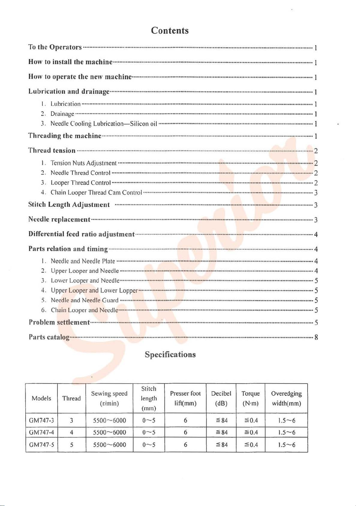
Specifications
Models
GM747-3 3 5500- 6000
Thread
Sewing speed
(r/min)
Stitch
length
(mm)
0-5
Presser foot Decibel Torque
lift(mm) (dB) (N·m)
6
~84
~0.4
Overedging
width(mm)
1.5--6
4
...
....
......
5
8
;;a
GM747-4
GM747-5
4
5
5500-6000
5500-6000
0-5
0--5
6
6
84
~84
~0.4
~0.4
1.5-6
1:5-6
Page 3
To the operator
Thank
you
very
much
for
using our High speed, Straight Needle, Overlock Safety Stitch Machine.
operating
machine.
correct direction
this
machine. please study this book thoroughly. understand the functions
Then
it
ATTENTION:
of
will
help
Because this
motor.
you
to
increase your sewing efficiency
is
an
high speed machine.
How to install the machine
1.
Install
the
enclosed.
IOOmm,and
2. Setting the
3 .
Install
Be
4.
NOTE:
machine according
In
case
of
semi-submerged, the distance between Needle plate top surface
for
fully-submerged
pedal
the
cloth waste chute. thread stand
sure the motor turning direction
The dimensions
is
of
clutch motor
of
motor pulley
about
to
the table
5mm.
to
the
is
How to operate the new machine
Please
run
thereafter
the new machine
the
machine
may
be
operated
in
the ftrst four at 20%less
up
to
left
side
as
parts list.
c.Jockwise.
and
sewing
maximum
cut-out
and
And
speed
speed.
and
quality.
Do
not
run
it
before
filling
diagram, Cushion Rubber
the
pedal
of
the belt can
are
speed
than
presser
shown
maximum.
be
pressed
in
Table I.
foot
Then replace
oil
and
lift
at
inward
and
features
and
making
and
Rest
Table
Top
right ride.
about
the
Before
of
sure
Board
is
about
JOmm.
new
oil
the
the
as
and
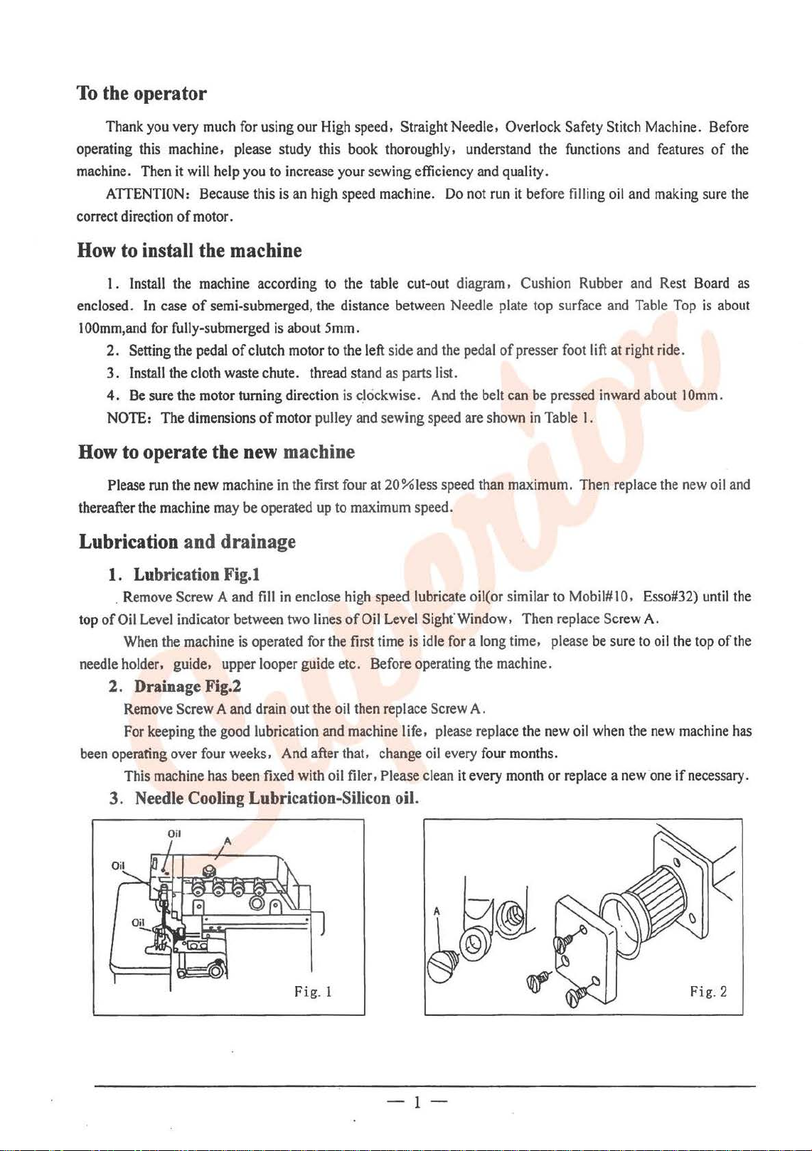
Lubrication and drainage
1. Lubrication Fig.l
.
Remove
top
of
Oil
When
needle
holder. guide, upper looper guide etc. Before operating the machine.
2.
Remove
For
been
operating over
This
3.
Screw A
Level
indicator between
the
machine
Drainage
Screw A and
keeping
machine
Fig.l
the
good
four
has
and
ftll
in
enclose
two
is
operated for the ftrst time
drain
out the
lubrication
weeks,
been
And
ftxed
with
high
lines
of
oil
and
machine
after that, change
oil
ftler
speed lubricate oil( or similar
Oil
Level
is
then
replace
life,
, Please clean
Needle Cooling Lubrication-Silicon oil.
Oil
A
Sight'Window. Then replace Screw A.
idle
for a long
Screw
please
oil
every
A.
replace the
four
it
every
time,
months.
month
to
Mobil# I 0,
please
be
new
oil
when
or replace a
sure
to
the
new ·one
Esso#32)
oil
the
new
machine
if
necessary.
until
top
of
the
the
has
Fig. 1 Fig.2
-1-
Page 4
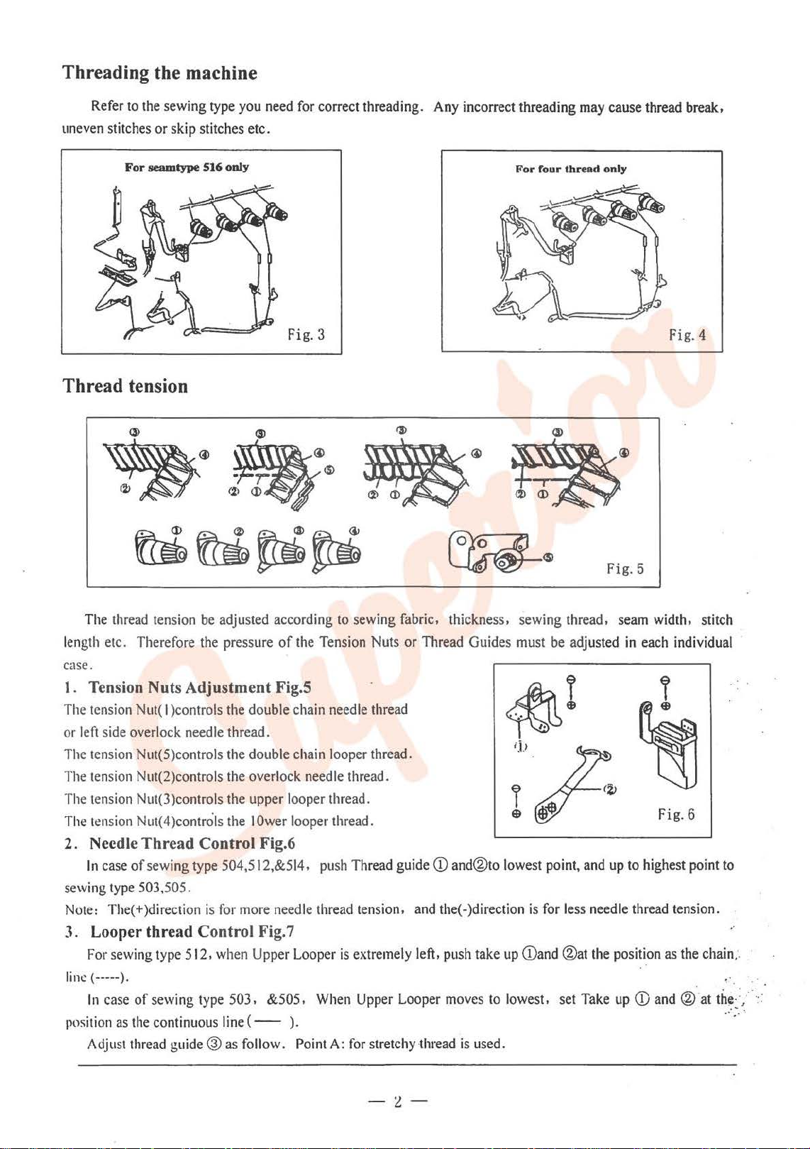
Threading the machine
Refer
to
the
uneven
sewing type
stitches or skip stitches etc.
For
seamtype
516
you
only
Thread tension
need
for
correct threading.
Any
incorrect threading
For
four
may
thread
cause thread break,
only
Fig. 3 Fig.4
The
thread
tension
length etc. Therefore
case.
l.
Tension Nuts Adjustment Fig.S
The
tension
or
left
The
tension Nut(5)controls the double chain looper thread.
The
tension Nut(2)controls
The
tension Nut(3)controls
The
tension
2. Needle
In
sewing
Note:
Nut(
side overlock needle thread.
Nut(
Thread
case
of
sewing
type
503,505.
The(+)direction
be
the
I )controls
4 )controls
Control Fig.6
type
is
adjusted according to sewing fabric, thickness, sewing thread,
pressure
the
the
the
the I Ower
504,512,&514.
for
of
the
Tension Nuts or Thread Guides
double chain
overlock needle thread.
upper looper thread.
more
needle
needle
looper thread.
push
Thread guide
thread tension ,
3. Looper thread Control Fig. 7
For
line ( -----
In
case of sewing
position
Adjust
sewing type 5
).
as
the
thread guide@ as follow.
12,
when Upper Looper
type
503. &505.
continuous line (
--
).
Point
is
When
A:
for
thread
and
extremely left,
Upper
Looper
stretchy thread
must
be
CD
and®to lowest point, and
the(-)direction
push
take
moves
is
used.
is
up
<Dand
to
lowest. set
for
Fig.
5
seam
width. stitch
adjusted
less
®at
Take
in
each individual
Fig.6
up
to
highest point to
needle thread tension. .
the
position as
up
CD
and
the
chain;.
@)"at
th~·:/
..
'- '
-:l-
Page 5
Point
B:
for seaming and blind stitch hemming. Point
Adjust Thread
Point D: for stretchy thread
NOTE: The direction
guide@
as follows.
is
used. PointE: for seaming and blind stitch
is
for more thread
in
sewing seam.
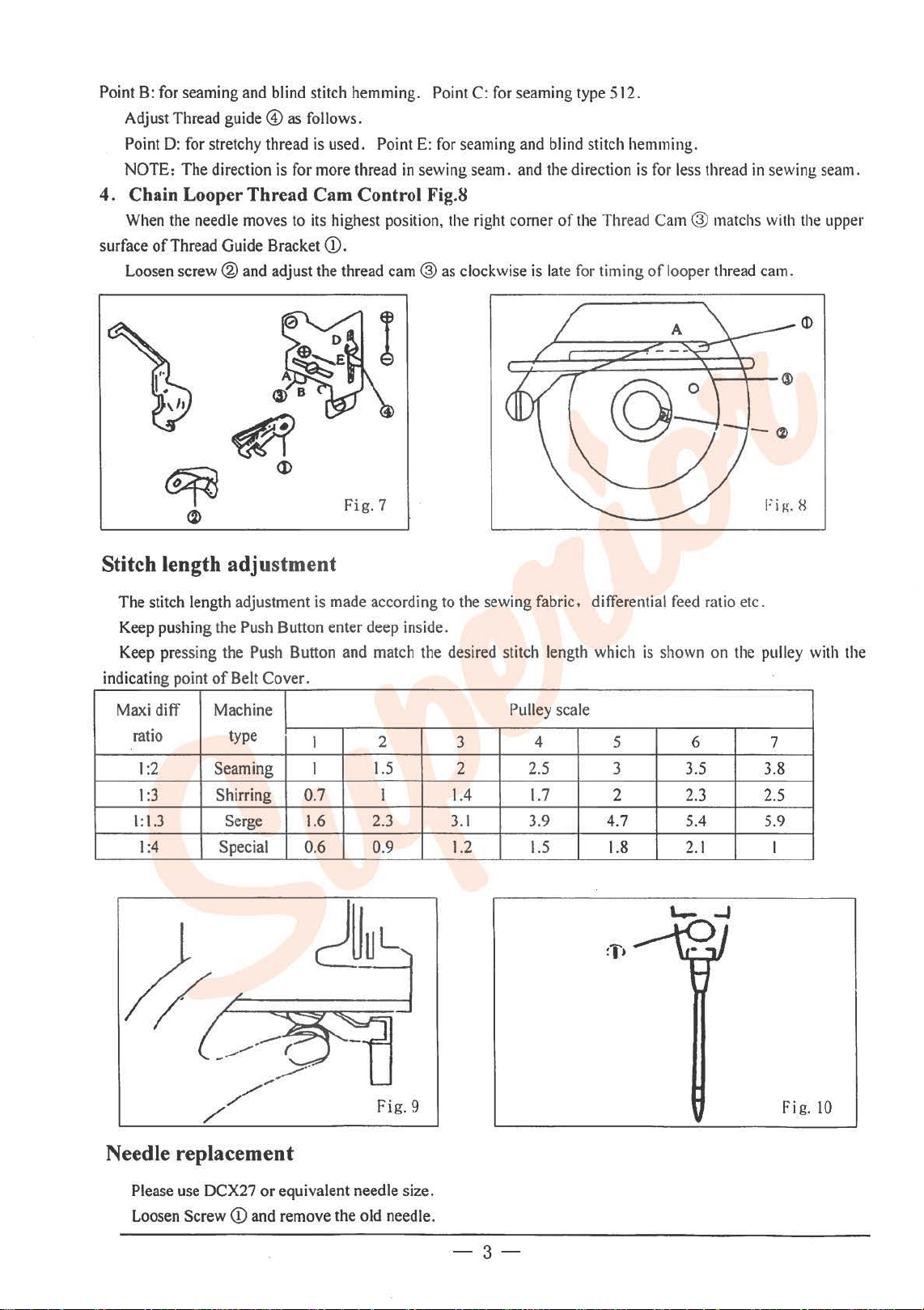
4. Chain Looper Thread Cam Control Fig.S
When
the needle moves to
surface ofThread Guide Bracket Q).
Loosen
screw®
and
its
highest position,
adjust the thread
cam@
the
as
Fig. 7 Fig. H
C:
for
seaming type 512.
right corner
clockwise
and
the direction
of
is
late for
hemm
ing.
is
for
less thread
the
Thread Cam ® matchs
timing
of
looper thread cam.
in
sewing seam.
with
the
upper
Stitch length adjustment
The stitch length adjustment
Keep
pushing the Push Button enter deep inside.
Keep
pressing the Push Button and
indicating point
Maxi
diff Machine
ratio type
1
:2
I :3
1:1.3 Serge
1:4
of
Belt
Cover.
Seaming I
Shirring
Special
is
made according
I
0.7
1.6
0.6 0.9
match
2
1.5
I
2.3
to
the sewing fabric. differential
the desired stitch length which
Pulley scale
3
2 2.5 3
1.4
3.1
1.2 1.5 1.8
4
1.7
3.9
5 6 7
2
4.7
is
shown
feed
3.5
2.3
5.4
2.1
ratio etc.
on
the pulley
3.8
2.5
5.9
I
with
the
Fig. 9
Needle replacement
Please
use
DCX27 or equivalent needle size.
Loosen
Screw
Q)
and
remove the old needle.
-3-
Fig.
10
Page 6
Insert
the needle which long gro0ve
faces
tighten Screw (i).
Differential feed ratio adjustment
you
and
push
it
up
deep into the needle hole until
it
stops
and
The ditlerential teed ratio
when
the
Uthcrcise
Loosen
shrinking
Note:
b~
set
over
I
I
movement
the
fabric
Nut
the
fabric
When
the
of
be
Q)
then turn screw ®
then tighten Nut (D.
the surface
scale
its
Main
shrinked.
ratio can
is
the ratio
feed
of
adjusting level@
be
Scale I 2
1:1.3
-
1:0.7 1:0.9
Ditlere-
I
tHial
Feed
1:2
I
:3
1:0
.7 I :I
1:1
I:
ratio
1:4
I:
1.1
1:1
I
Parts relation and timing
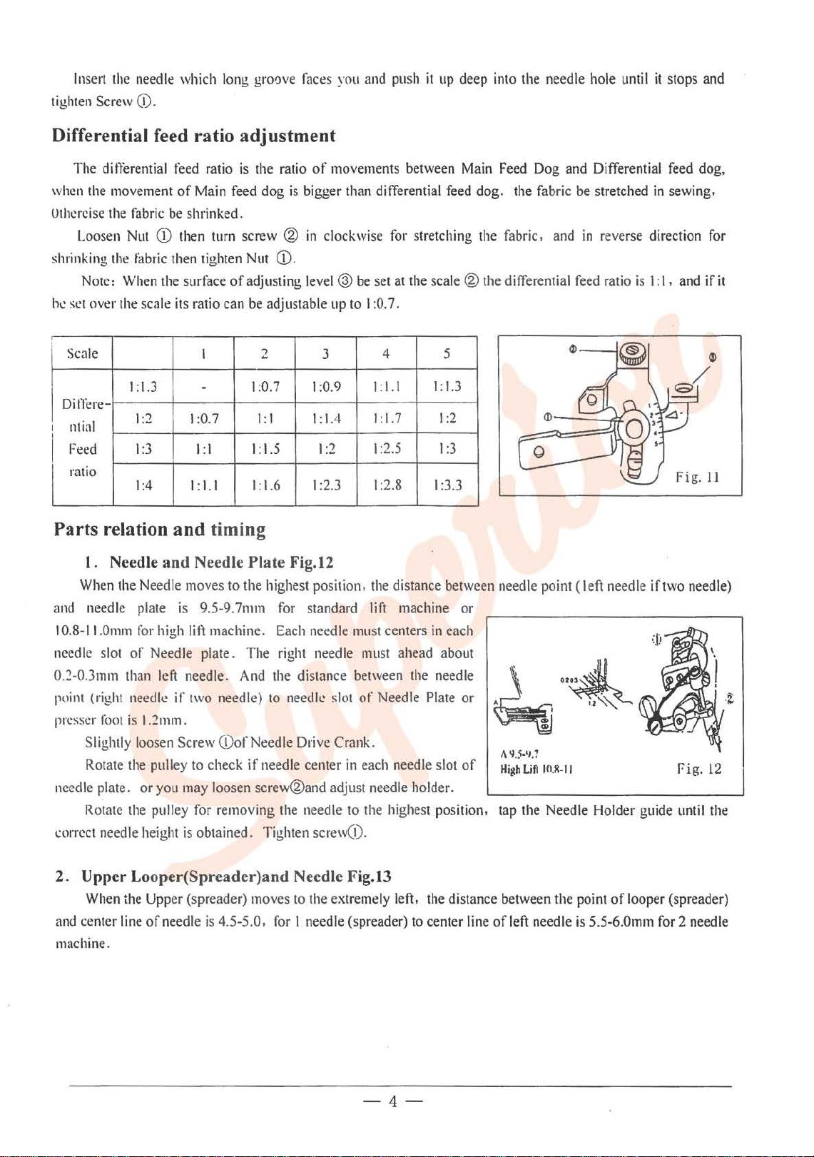
1. Needle and Needle Plate Fig.12
When
the
Needle moves to the highest position.
and
needle plate
10.8-II.Omm
needl
e slot
of
0.::!-0.3mm
point
presser
than left needle.
(right needle if two needle)
foot
is
Slightly loosen Screw
Rotate
the pulley
needle plate. or you
Rotate
~:orrcct
the
needle height
is
9.5-9.7mm
for
high
lift machine.
Needle plate. The right needle must ahead about
And
1.2mm
.
Q)of Needle Drive Crank.
to
check
if
may
loosen screw®and adjust needle holder.
pulley for removing
is
obtained. Tighten screw(!).
of
movements between
dog
is
bigger than differential feed dog. the fabric
in
adjustable
1.5
.6
for
standard
Each
needle
clockwise
up
3
I:
1.4
1:2
I
:2.3
be
to
must
set
I :0.7.
I :I. I
I:
1:2
1:2.8
the
lift
for
stretching the fabric,
at
the
4 5
1.7
.5
distance between needle point (left needle iftwo needle)
machine or
centers
Main
scale®
1:1.3
1:2
I
:3
1:3.3
in
each
the distance between the needle
to
needle slot
needle center
the
needle
of
Needle
in
each
to
the highest position, tap the Needle Holder guide
needl
Plate
e slot
or
of
Feed
Dog and Differential
and
the differential
t\
'15-'1.1
High
Lifl
IOJ~·II
be
stretched
in
reverse direction
feed
ratio
is
feed
in
sewing.
I:
1.
and
Fig.
J7ig.
until
dog,
for
if
ll
12
the
it
2. Upper Looper(Spreader)and Needle Fig.l3
When
the
and
center
Upper (spreader) moves to
line
of
needle
is
4.5-5.0,
the
extremely left, the distance between the point
for
I needle (spreader) to center line
of
left needle
machine.
-4-
of
looper (spreader)
is
5.5-6.0mm for 2 needle
Page 7
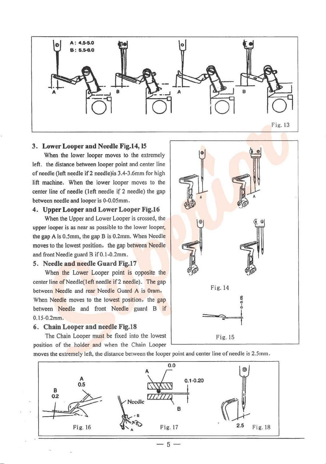
A: 4.5-5.0
8:
5.6-6.0
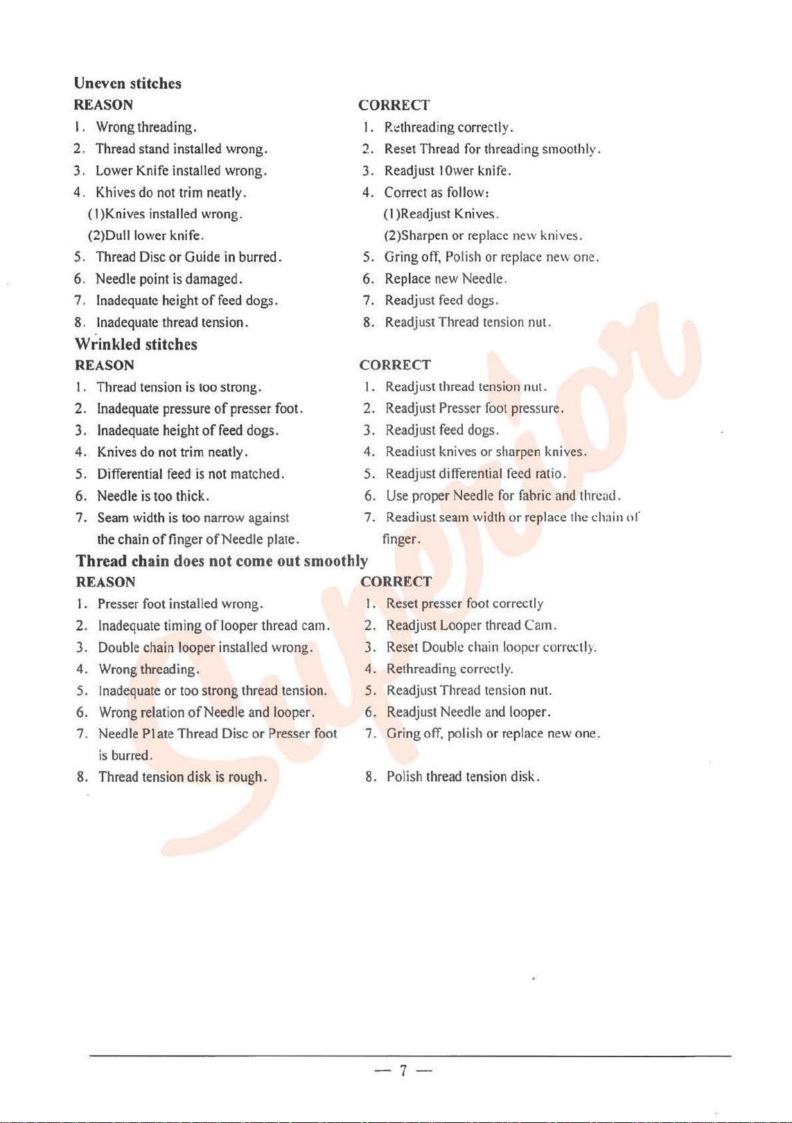
3.
Lower Looper and Needle Fig.14,
When
the
lower
looper
left.
the
distance
of
needle
(left
lift
machine.
center
line
between
4.
upper
the gap A
moves
and
5.
center
between
When
between
0.15-0.2mm.
6.
position
moves
needle
Upper Looper and Lower Looper Fig.16
When
looper
is
to
the
front
Needle
Needle and needle Guard Fig.17
When
line
ofNeedle(Ieft needle
Needle
Needle
Needle
Chain Looper and needle Fig.18
The
Chain
of
the
extremely
needle
When
of
needle
and
the
Upper
is
as
O.Smm,
lowest
the
Lower
moves
the
between
if2
the
(left needle if 2 needle) the
looper
and
near
the
position. the gap
guard
and
rear Needle
to the
and
Looper
holder
left,
moves
looper
needle)is 3.4-3.6mm
lower
is
0-0.0Smm.
Lower
as
possible
gap B
point
looper
Looper
is
0.2mm.
to
to
and
the
between
B if 0.1-0.2mm.
Looper point
lowest
front Needle
must
be
and
when
the distance
is
if2
needle).
Guard A is
position, the
fixed
into
the
between
the
moves
is
lower
When
opposite the
guard
Chain
15
extremely
center
for
to
crossed,
looper,
Needle
Needle
The
Oram,
B if
the
lowest
Looper
the
line
high
the
gap
the
gap
gap
looper
point
and
~
center
Fig.
Fig.
line
14
8
0
I
0
• I
15
of
needle
0
is
2.Smm.
Fig. 13
0.0
A
0.5
Fig.
16
A\
r 0.1..().20
~
ccdlc
f///lZ"\~
-a
~b
A
Fig.
f
17
-5-
2.5
Fig.
18
Page 8

Problem settlement:
Needle
break
REASON
I . Needle installed wrong.
2. Wrong needle size.
3.
Needle is bended.
4.
Wrong relation with Needle Guard.
5.
Wrong relation with looper.
6.
Needle does not center the needle.
Slot
of
Thread
Needle
break
Plate
or
Presser Foot.
REASON
I.
Inferior quality
2. Thread thicker than Needle hole.
3.
Wrong threading.
4.
Thread tension is too strong.
5.
Needle installed wrong.
6. Thread Stand installed wrong.
7. Over heat
(2 )Wrong setting
8.
Thread Disc
9.
Wrong relation
10. Needle . Looper needle Plate and guide
is burred.
of
thread.
ofNeedle:
of
Needle Guard
or
Guide is burred.
of
Needle
(J)NO silicon oil
and
Looper.
Skip stitches
REASON
1. Wrong relation
2.
Wrong threading.
3.
Needle installed wrong.
4. Inadequate thread tension
too strong.
5.
Looper point is damaged.
6.
Needle is bended.
7. Wrong installed needle Guard .
ofNeedle
and Looper.
or
tension
Loosen stitches
REASON
I . Wrong threading
2. Thread is thicker than Needle
hole.
3.
Tension Disc do not press thread
properly.
4.
Needle thread is not 1 ubricated.
5. Wrong setting
Loopers.
ofNeedle
and
CORRECT
1. Reset needle correctly.
2.
Use properly needle for fabric and thread.
3.
Replace new needle.
4.
Readjust Needle guard.
5.
Readjust looper.
6.
Readjust the Needle Plate and Presser Foot.
CORRECT
I. Use good quality thread.
2.
Use proper Needle for fabric and thread.
3.
Rethreading correctly.
4.
Readjust thread tension nut.
5. Reset needle correctly.
6. Reset thread stand for threading smoothly.
7.
(l)FillinSiliconeoil.
(2)Readjust Needle Guard.
8.
Gring
off
polish
or
replace new one.
9. Readjust Needle and Looper.
10. Grind .
off
, polish
or
replace new one.
CORRECT
I.
Readjust Needle and Looper.
2. Rethreading correctly.
3.
Reset Needle correctly.
4.
Readjust Thread Tension Nut.
5. Replace new
6.
Replace new one.
7.
Readjust Needle guard.
one.
CORRECT
I.
Rethreading correctly.
2.
Use proper Needle.
3.
Reset Tension Disc properly.
4.
Fill silicon oil.
5.
Readjust needle and loopers.
Page 9
Uneven stitches
REASON
I.
Wrong
2. Thread stand installed wrong.
Lower
3.
Khives
4.
(I
(2)Dull
5. Thread Disc or Guide
6. Needle point
7.
8. Inadequate thread tension.
threading.
Knife
installed wrong.
do
not
trim
)Knives
Inadequate height
installed wrong.
lower
knife.
is
damaged.
neatly.
in
of
feed dogs.
burred.
CORRECT
Wrinkled stitches
REASON
I . Thread tension
2. Inadequate pressure
3. Inadequate height
Knives
4.
5. Differential
6. Needle
Seam
7.
the
do
is
width
chain
is
too
strong.
of
of
feed
not
trim
neatly.
feed
is
not matched.
too
thick.
is
too narrow against
of
finger
of
Needle plate.
presser foot.
dogs.
Thread chain does not come out smoothly
REASON
I.
Pre
sser
foot
installed wrong.
2. Inadequate timing
3.
Double
4.
Wrong
5.
Inadequate or
6.
Wrong
7. Needle Plate Thread Disc or Presser
is
8.
Thread tension disk
chain looper installed wrong. 3.
threading. 4. Rethreading correctly.
relation ofNeedle
burred.
of
looper thread cam.
too
strong thread tension.
and
is
rough.
looper.
foot
I .
R.:thread
2. Reset Thread
3. Readjust
4. Correct
(I
(2)Sharpen or replace
5. Gring
6. Replace
Readj
7.
8. Readjust Thread tension nut.
ing correctly.
for
threading smoothly.
!Ower
knife.
as
follow
:
)Readjust Knives.
off,
Polish or replace
new
Needle.
ust
feed
dogs.
new
knives.
new
CORRECT
I . Readjust thread tension nut.
2. Readjust
3. Readjust
4. Readiust knives or sharpen knives.
Readjust
5.
Use
6.
7. Readiust
finger.
Presser foot pressure.
feed
dogs.
differential
proper Needle
seam
for
width
feed
ratio.
fabric
and
or replace the chain
CORRECT
Reset
I.
2.
5. Readjust Thread tension
presser
Readjust
Reset
Double
6. Readjust Needle
7.
Gring
off,
8.
Polish thread tension disk.
foot
correctly
Looper thread Cam.
chain looper co
nut.
and
looper.
polish or replace
rrectl
new
one.
thread.
or
y.
one.
-7-
Page 10
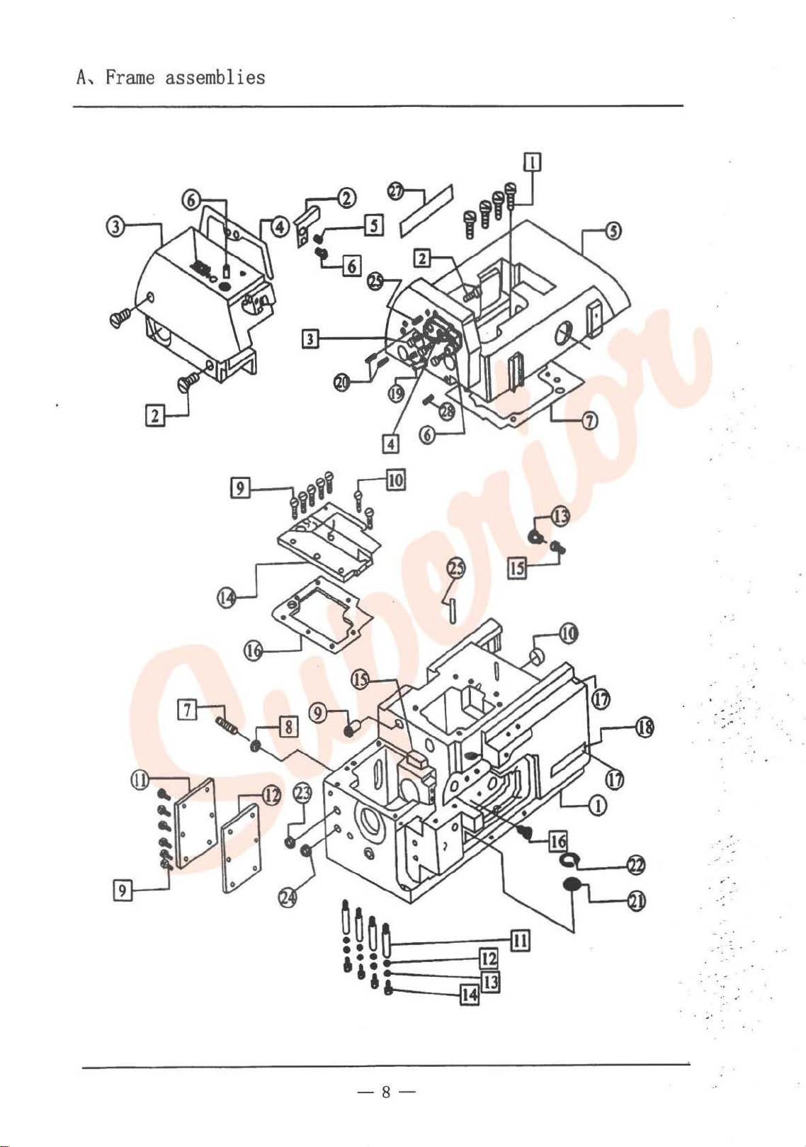
A,
Frame
assemblies
_______
-8-
. . .
_____..
. . .'
. .
.. -
. -·
~
-
...
' ..
~·
-
.
.
·
·~
.,.
. -
~
. .
..
. -
Page 11
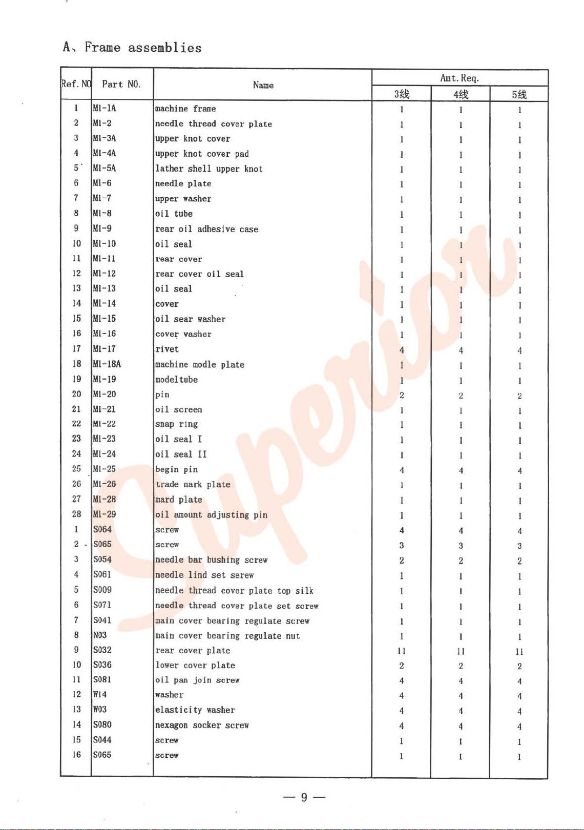
A,
Frame
Ref.NC
1
2
3
4
5'
6
7
8
9
10
11
12
13
14
15
16
17
18
19
20
21
22 Ml-22
23
24
25
26
27
28
1
2
.
3
4
5
6
7
8
9
10
11
12
13
14
15
16
Part
MI-lA
M1-2
Ml-3A
Ml-4A
M1-5A
Ml-6
Ml-7
Ml-8
M1-9
Ml-10
MI-ll
Ml-12
Ml-13
Ml-14
Ml-15
Ml-16
M1-17
M1-18A
M1-19
M1-20
Ml-21
Ml-23
Ml-24
Ml-25
M1-26
M1-28
All-29
S064
S065
S0
54
S061
S009
son
S04l
N03
S032
S036
S081
Wl4
W03
S080
S044
S065
assemblies
NO.
machine
needle thread cover
upper knot cover
upper knot cover
lather
needle
upper washer
oil
rear
oil
rear
rear
oil
cover
oil
cove~
rivet
machine
model
pin
oil
snap ring
oil
oil
begin pin
trade
mard
oil
screw
screw
needle bar bushing screw
needle
needle thread cover
needle thread cover
main
main
rear
lower cover
oil
washer
elasticity
nexagon
screw
screw
frame
shell
plate
tube
oil
adhesive case
seal
cover
cover
seal
sear
washer
washer
modle
tube
screen
seal
I
seal
II
mark
plate
amount
lind
cover bearing regulate screw
cover bearing reg
cover
pan
join
socker screw
Name
plate
pad
upper knot
oil
seal
plate
plate
adjusting pin
set
serew
plate
plate
ulat
plate
plate
screw
washer
top
set
e nut
silk
screw
A.mt.
Req.
3~
1
1
1
4~
I I
I 1
I I
1 I
1 1
1
1
1
I I I
I
1
I I
1
1
I I
1
4
I
1
2
1
1
1
I
I I
1
I I
I
1 I
I I
I I
4
1 I
1
2 2
I
I 1
1 1
1 1
4
1
1 I
1
4
3
2
1
1
I I
1
1 1
11
4
I I
I I
4
3 3
2 2
I I
I I
I
II
2 2
4
4
4
4
I
1
4 4
4
4
4 4
I
I I
5~
I
I
I
1
I
I
I
4
I
1
1
4
I
4
I
I
I
11
2
4
4
I
-9-
Page 12
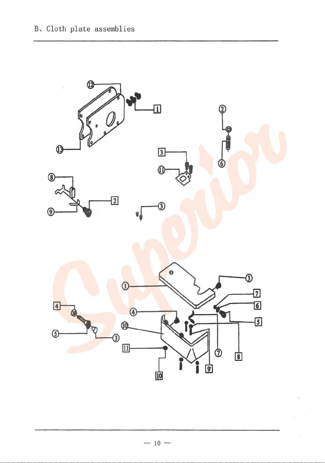
B,
Cloth
8,__...,
plate
assemblies
-10-
Page 13
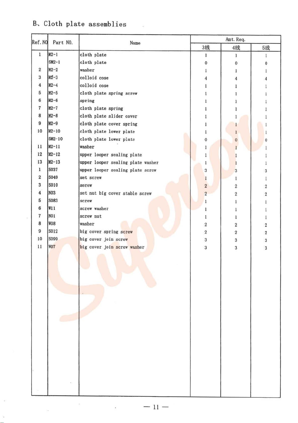
B,
Ref.
2
3
4
5
6
7
8
9
10
11
12
13
1
2
3
4
6
6
7
8
9
10
11
Cloth
NO
M2-l
1
5M2-I
M2-2
111-3
M2-4
M2-5
M2-6
M2-7
M2-8
M2-9
M2-10
5M2-10
M2-11
M2-12
M2-13
S037
S049
SOlO
N03
S083
Wll
N01
W08
S012
S099
W07
plate
Part NO.
assemblies
Name
cloth
plate
cloth
plate
washer
colloid
colloid
cloth
spring
cloth
cloth
cloth
cloth
cloth
washer
upper looper
upper looper
upper looper
set
serew
set
screw
screw washer
screw nut
washer
big cover spring screw
big cover
big cover join screw washer
cose
cose
plate
spring screw
plate
spring
plate
slider
plate
cover spring
plate
lower
plate
lower·
sealing
sealing
sealing
screw
nut big cover
join
screw
cover
plate
plate
plate
plate
plate
stable
screw
washer
screw
Amt.
3~
1
0
1
4
1
1
1
1
1 1
1
1
0
I
1
1
3
I
2
2
1
I I
1
2 2
2
3 3
3
Req.
4~
1
0 0
1
4
1 1
1
1
I 1
1 1
1
0
1 1
1 1
1
3 3
l 1
2 2
2
1
1
2
3
5~
1
1
4
1
1
1
1
0
1
2
1
1
1
2
2
3
3
-11-
Page 14
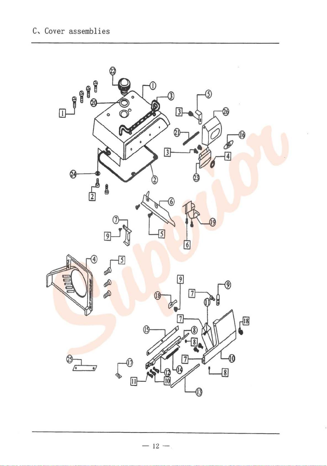
c,
Cover
asse
mblies
=----
-1
2-
Page 15
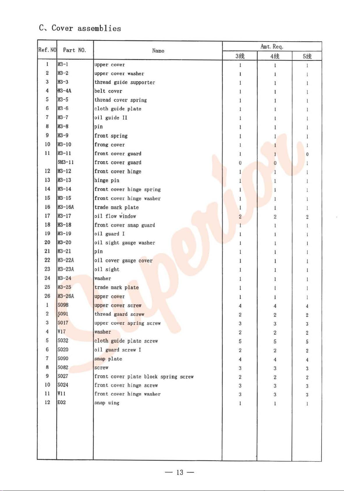
C,
Cover assemblies
Ref.
NC
Part
NO.
1
M3-l
2
M3-2
M3-3
3
4
jM3
-4A
5
M3-5
M3-6
6
7
M3-7
M3-8
8
9
M3-9
10
M3-10
11
M3-11
5M3-ll
12
M3-12
13
M3-13
14
M3-14
M3-15
15
16
M3-16A
17
M3-17
M3-18
18
M3-19
19
20
M3-20
21
M3-21
22
M3-22A
23
M3-23A
24
M3-24
25
M3-25
26
M3-26A
1
S098
2
~091
S017
3
Wl7
4
S032
5
6
S020
S090
7
R
S082
9
S027
10
S024
Wll
11
12
E02
Name
upper cover
upper cover washer
thread guide supporter
belt
cover
thread covet· spring
cloth
guide
plate
oil
guide
II
pin
front
spring
frong cover
front
cover guard
front
cover guard
front
cover hinge
hinge pin
front
cover hinge spring
front
cover hinge washer
trade
mark
plate
oil
flow
window
front
cover snap guard
oil
guard I
oil
sight
gauge
washer
pin
oil
cover
gauge
cover
oil
sight
washer
trade
mark
plate
upper cover
upper cover screw
thread guard screw
upper cover spring screw
washer
cloth
guide
plate
screw
oil
guard screw I
snap
plate
screw
front
cover
plate
block
front
cover hinge screw
front
cover hinge washer
snap uing
spring
screw
Amt.
3~
1 1
I 1
I
I
I I
1 I
1 I
1
1
I
I
0
I
1 1
I I
I
I
2 2
I
1
I
1 I
I I
1
1
1 1
1 1
4
2
3
2
5 5
2
4
3 3
2
3 3
3 3
1 1
Req.
4~
I I
I 1
1
I I
I I
I 0
0 I
1 I
I
1 I
1 1
I 1
1 I
1
1
4
2
3
2
2
4
2
5~
I
I
I
I
I
I
I
I
I
2
I
1
I
I
I
I
4
2
3
2
5
2
4
3
2
:l
3
I
-13-
Page 16
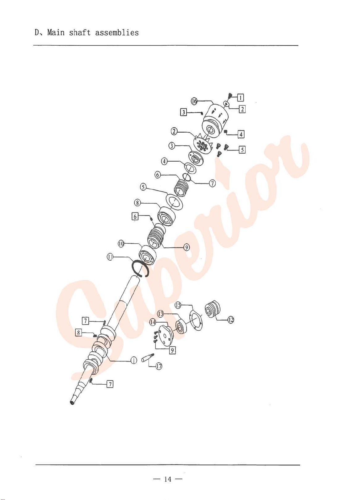
D,
Main
shaft
assembl.
1es
-14-
Page 17

..
D,
Main
!Ref.NC
1
2
3
4
5
6
7
..
8
9
10
11
12
13
14
15
16
17
I
2
3
4
5
6
1
8
9
shaft
Part
NO.
M4-l
M4-2
M4-3
M4-4
M4-5
M4-6
M4-7
M4-8
M4-9
M4-10
M4-ll
M4-12
M4-13
. bearing
M4-14
5M4-14
M4-15
M4-16
5M4-17
S073
W03
S070
S085
S032
S043
S078
S0l9
S022
assemblies
Name
main
shaft
wheel
rear
shaft
bearing cover
rear
shaft
bearing cover
main
shaft
main
shaft
spring
busing
washer
Seal ring
main
shaft
queen
shaft
oil
pump
worm
main
shaft
bearing
shaft
end bushing washer
main
shaft
light
bushing
80200
bearing cover
beari.
ng
cover
bearing cover washer
pulley
bulgy pulley bearing
pulley screw
pulley screw washer
pulley
pulley
set
set
screw
screw
rear shafting bearing cover screw
oil
pump
worm
screw
screw
screw
bearing cover screw
washer
bearing
Amt.
Req.
3~
1
1 I
1
1
1 1 I
1 1
1 1
1
4~
I 1
1
I
1 I
1 I I
1 I I
l
I
l
1 I 0
0
1 I
1
0
1 I
1 1 I
1
1
1
1 I
l
0 I
1 1
0
l I
1 1
3 3
1 I 1
2
1
3
2 2
1
3 3
5~
1
1
1
I
1
I
1
1
0
1
3
I
.·
·
•·
..
~~·~
..
-.~.
0
,-;
••
-15-
Page 18

E,
Needle b
ar
asseml·
1es
-16-
Page 19

E,
Needle bar
Ref.
NO
Part
MS
-1
1
2
&15-2
3
MS-3
4
M5-4
M5-5
5
6
M5
-6
M5-7
7
8
M5-8
9
M5-9
10
M5-10
11
M5-ll
12
M5&1
5-13
13
14
M5-14
15
M5-
16
MS-16
17
MS51115-17
&15-18
18
19
M5-
20
MS-20
21 MS-21
22
MS-22
M5-23
23
24
M5-24
25
M5-25
26
MS-26
27
4M5-27
31115-27
5M5-27
28
M5-58
29
M5-59
I
S0
57
2
S102
3
S055
S043
4
5
S074
S053
6
7
SOOl
8
S006
S012
9
10
S009
I I
E0
1
12
15
17
19
assemlies
NO.
needle bur d
eccentric
needle bar
sn
ap
throat
oil
needle bearing
washer
th
roat
oil
throat
needle driving
seal
needle bar
ap ring
sn
balance block
needle bar flame
throa~
needle bar connecting rod
connecting
washer
throat
needle bar
oil
oi 1
plasties
oil
needle
needle
needle
needle
oil
snap ring screw
hexagon
balance block
frame rock
shaft
screw
screw
screw
screw
screw
snap ring
shaft
shaft
ring
driving crank
wick
ring
cli
p guide pin
wick
bar rock crank
ring
rear
bar
shaft
link
clip
felt
wick
tube
wick
clamp
clamp
clamp
seal
socket screw
shaft
position
Name
riving
guide bushing
frame
ro.:k
bush
ing
back
shaft
bearing
driving copper bearing
shaft
rock
crank
crank
pin
position
set
screw
screw
screw
shaft
Awr..
3~
1 1
1
1
I
1
1
I
I
I I
I
1
I
2
1
2
1
0
I 0
I
I
1
1
I
I 1
I
1
2 2
0
I
0
1
I
4
I 1
2 2
3
2 2
1
1
1
I I
5 5
I
Req.
4~
1 1
1 1
1
I I
I I
1
I I
1
I I
I I
2 2
1 1
2
1 1
I 0
I
I I
1 I
1 I
1 I
1
1
I 0
0
0
I
2
4
3
1
I
1
I
5~
1
I
1
I
1
2
I
I
I
1
I
2
0
1
I
2
4
1
2
3
2
1
1
1
1
5
I
-17-
Page 20

F,
Thread guide assemblies
-
lH
Page 21

F,
Thread guide assemblies
Ref. NO
10*
11
12
13
14
1
2
3
4
5
6
7
8
9
Part
M6-1
M6-2
M6-3A
M6-4
M6-57\
M6-6
M6-7
M6-8A
M6-9
5M6-9
M6-10
M6-ll
M6-12
M6-13
M6-14
NO.
thread tension spring
thread tension screw
thread ·tension nut
thread tension spring
thread tension spring
thread tension
thread tension
thread guide
upper thread take-up
upper thread take-up
oil
box
oil
felt
thread guide
o
11
box
oil
feet
washer
15 M6-15 tension spring
16
M6-16
17
M6-17
18
M6-18
19
M6-19
20
M6-20
21
M6-21
5M6-21
22
M6-22
23
M6-23
4M6-24
24
3M6-24
5M6-24
25
4M6-25
3M6-25
5M6-25
26
M6-26A
27
5&16-27
28
5H6-28
29
5616-29
30
M6-30
5&16-30
31 M6-31
32
M6-32
1
S099
S035
2
S016
3
4
S061
5
SOI5
S033
6
thread
controller
spring
thread
thread
thread
thread
thread
teat
controller
plate
plate
mark
mark
needle guard
thread tension
front
needle guard
front
needle guard
front
needle guard
throat
throat
throat
plate
plate
plate
thread guide
thread guide
needle guard I
needle guide
needle guard barcket
needle guard barcket
snap
plate
snap
plate
screw
throat
front
throat
plate
needle snap screw
plat
thread guide bolder screw
.
oil
box
set
Name
retainer
disc
disc
washer
disc holder
disc guide bushing
positionign rod
barcket
guide
guide
spring
II
washer
screw
barcket screw
screw
house
Amt.
Req.
3~
4~
1 2
3
4 4
3 4
3
4
3 4
6 8
3
2
4 4
2 2
I 1 0
0
0
1 1
I I
I 1
1 1
1
1
1
1
I 1 I
1
I
2
1
1
0
I
2
0
1
0
0
1 I
1 1
2
1 I
1
0
1 I
2
1
0 0
0
1
1 0
0
I 2
0
0
0
0
0
0 0
I
0
1
1
I I
2
I
2
2
1
I 0
0
I
I I
2
1
2
2
I
5~
2
4
4
4
8
I
I
I
I
I
1
I
2
0
I
2
0
1
0
0
I
I
I
1
1
1
1
I
2
1
2
2
I
-19-
Page 22

F,
Ref.
7
8
9
10
11
12
13
14
15
Thread
NO
Part
S072
S005
S023
W07
S017
Sl03
S019
S104
S045
guide assemblies
NO.
oil
box
washer
rear
needle guard screw
needle guard screw
needle guard washer
thread take
snap
plate
snap
plate
snap
plate
screw
set
up
screw
screw I
screw
set
screw
screw
II
Name
Amt.
Req.
3~
1
2 2
1
1 1 1
2 2 2
2 2
1
1 1
2
4~
1 1
1 1
1 1
2
5~
2
2
1
2
-20-
Page 23

G,
Upper
oper assembl '
lo
1es
-21
-
Page 24

G,
Upper
Ref.
NC
I
:t
3
-1
!i
7
ll
!l
10
II M7-II
12
13 M714
Iii
J(i
17
Ill
I!J
20 M7-20
21
22
2:1
24
2:i
:w
27
21! M7-28
2!l
:!()
:n
:12
:l:l M7-
I
2
:1
I
:1
li
7
H
!I
10
Part.
M7-l
M7-2
M7-3
5M7
-3
M7
·4
M7-
G
M7-7
M7-ll
M7
-9
M7-IO
M7-l2
l3
M7-14
M7-15
M7
-Hi
M7-17
M?-18
Mi-
l!l
M7-21
M7-22
M7-23
Ml-24
M7
·2:i
M7-2!i
M7
-27
m29
ll7-:30
m-
:H
iiMi
-
:11
M7
-n
:1:1
SOi:J
SO:lH4
SO!iH
11'1::!
SOO!l
Sl!ll
sn:w
W0-1
so:12
so:n
looper
NO.
looper
looper
thickness
thickness
upper
hig
upper
upper looper
upper
upper
upper
connecting
washer
oil
upper
oi 1 felt
oi 1 felt
oi
lwick
s<:rceu
t'el
thread
upper
oil
oi
1 t.uhe
oi I tuhe
thread
upper
upper looper
shaft.
lower
Loop<:r
IIJ>JH!r
upper
t.h
reading
two
shat't.
SCI'I!\1'
upper
IIJIIWI' I
I
ink
lll'Xfi!(OII
upper
washer
upper
thn
assemblies
link
link
holder
washer
washer
looper
washer
looper
looper
looper
looper
wick
looper
t.
plate
looper
seal
Looper t.hreud
hearing
loopet·
looper
looper
fo
I'
serew
looper
pin st:t
looper
looper
:ad
shaft
shaft
shaft
shaft
shaft
shaft
rod
shaft
shaft
oil
plate
hold
er
snap
shaft
amount
ooper shaft
amount.
regulating
shaft.
guaicl
holder
crank
crank
t.uhe
l.h
t·eacl gn i dt'
shaft.
scrPw
SOtkl!t.
shaft.
shaft. thread
regulating
SPI"P.\1'
Name
rear
foot
oil
seal
cnmk
har
pin
slide
plate
slide
guide
tht·ead
c:oppt'r
heariug
heariug
c:rauk
waslu·
:r
sc:n:w
bashing
bushing
bar
block
har
bracket
plate
plut.e
st·n:w
guide!
platt•
screw
3~
2
2
0
1
I
1
1
1
1
1
I
1
1
l
I
2
I
2
I
I
I
I
2
I
I
I
I
I
2
I
I
0
I
2
I
8
2
I
I
I
I
I
I
2
2
Amt.
Req.
2
2
I
0
I
I
I
I
I
I
l
1
l
l
1
2
I
2
I
I
I
I
2
I
I
I
I
I
2
I
I
I
0
2
I
H
I
I
I
I
I
I
2
2
5~
2
2
0
1
I
1
1
I
1
1
1
1
1
1
I
2
I
2
I
1
I
I
2
I
I
I
I
1
2
I
I
0
l
2
I
8
. 2
1
I
I
I
I
I
2
2
-22-
Page 25

G~
Upper
Ref.NC
11
12
13
14
15
16
17
18
Part
S037
S014
\fOB
S097
S062
S012
S095
S015
looper
NO.
screw
loopet·
looper
upper looper
upper looper
thread holder snap
thread holder snap
upper looper
assemblies
shaft
thread guide screw
shaft
thread guide washer
shaft
thread
shaft
thread
plate
plate
set
screw
Name
plate
plate
sctew
screw
screw
screw
Awt.
Req.
3~
I I
2
2
l I
I I I
I I
1
1
4~
2 2
2 2
I I
I
5~
I
I
I
I
-23-
.
Page 26

H,
Lower
looper assemblies
-24-
Page 27

H,
Lower
Ref.NC
1
2
3
4
5 MS-5
6
7
8
9
10
11 MS-11
12
13
14
1
2
3
4
5
6
7
R
9
10
Part
MS-1
!iMR
-1
MS-2
MS-3
MS-4
MS-6
MS-7
MS-8
M8-9
MS-10
AIS-12
MS-13
5M8-13
MS-14
5&18-14
S036
W04
SI01
S060
W12
W07
S022
S032
S067
SOlS
looper
assemblies
NO.
Lower
looper
washer
lower looper
oil
seal
lower looper
lower
looper
lower looper holder
lower looper crank
lower looper
cop
per washer
thread guide
lower looper thread guide
lower looper 3-tht·ead guide
lower looper
lower looper
lower
looper crank
lower looper crank
lo
wer
looper
elastic
crank screw
lower looper holder screw
lower looper holder washer
lower looper holder washer
lower looper screw
lower looper thread guide screw
crank screw
crank screw
shaft
shaft
front
rear
shaft
shaft
shaft
washer
Name
copp
er
washer
bushing
bushing
washer
screw
bushing
Amt.
3~
I
0
1
I I
I
I
1 I
2
I I
I I
1
1
I
I
0
I
0
I
1
I
1
1
l
I
I
0
0
Req.
4tt
I
0
I
I
I I
2
I
1
I I
1 0
0
I 0
0
I
I I
1
I I
I
I I
1 I
I
0
0
!)~
0
I
I
2
I
I
5
0
I
I
I
I
I
I
I
I
I
2
2
-25-
Page 28

I,
Front lower looper
assemblies
-26-
Page 29

l,
Front lower
Ref.
NO
Part
I
5M9-l
2
5M9-2
3
5M9-3
4
5M9-4
5
5M9-5
6
5M9-6
7
5M9
-7
8
5M9-8
9
5M9-9
10
5M9-IO
11
5M9-11
12
5M9-12
13
5M9-13
II
S005
2
SOI6
3
S060
4
Wl2
5
S028
6
SIOI
7
S04:l
8
S094
9
S093
10
E03
NO.
looper
Front looper
front
looper
front
looper
front
looper crank
regulating
regulating
oil
thread
front
looper
front
looper
frong looper
driving
driving
front
looper
front
looper thread guide screw
front
looper guide
front
loop
front
looper holder screw washer
front
looper crank screw
front
looper crank holder
nexagon
drivi
ng
driving
snap
ring
assemblies
shaft
shaft
plate
plate
shaft
shaft
shaft
lever
crank
slide
er
holder
socket
lever
lever
set
set
set
pin
Name
holder
regulding washer
front
bushing
rear
bushing
block
set
screw
set
screw
set
screw
screw
screw
screw
Amt.
Req.
3~
0 0
0
0
0
0 0
0 0
0
0
0
0
0
0 0 1
0
0
0 0
0
0 0
0
0
0
0
0
0
4~ 5~
0
0 I
0 I
0 2
0 I
0 I
0 I
0 I
0 I
0 1
0 I
0
0 1
0 I
0
0 I
0
I
I
l
2
I
2
2
I
I
-27-
Page 30

J,
Cam
assembli=es~
---------
2
-28-
Page 31

1~
Cam
Ref.NC
I 5
MIO-I
2 5MI0-2
5&110-3
3
4 5M10-4
!i
5MI0-5
5MI0-6
6
i
5MI0-7
5MJ0-8
8
9 5Ml0-9
10
5~110-10
11
5MIO-
!iMI0-12
12
13
5Ml0-13
5MI0-14
14
15
5MI0-15
16 5Ml0-16
17
5MI0-17
18
5MI0-18
5MI0-19
19
20
5MI0-20 tht·ead
21
5Ml0-21
5M10-22
22
23
5MJ0-23
24
5MJ'0-24
25
5MI0-25
26 5Ml0-26
I S002
S009
2
3 S!Ol
:I
Wl2
wor.
ii
li
N02
7
N03
H
S032
9 S003
S017
10
I I
SO:lR
12
S027
I
:1
lVII
14
S020
asse
Part
NO.
ll
mblies
link
bear
bearing
pin
shaft
s
haft
bushing
bushing(left)
oil
seal
cam
thread
thread
holder
washer
stopper
thread
2-thread
rear
thread
thread
thread
holder
holder
holder
presser
bearing
cam
set
crank
erank
crank
crank
thread
thread
thread
thread
thread
thread
washer
threud
snap
crank
(right)
guide
guide
bracket
guide
thread
thread
guide
guide
guide
tension
spool
disc
spool
nut
sna1>
screw
set
screw
washer
adjusting
adjusting
tensiou
t:eusion
guide
guide
guide
gui1le
guide
Name
ring
finger
plate
hook
gu i
de
guide
finger
tube
bushing
tube
tube
clamp
plate
spring
ring
screw
pin
washer
pin
nut
screw
screw
plate
screw
plate
scn~w
fiuger
Sill.
for 2-thread
hook SCl"I:IV
holder
ttlll
screw
sc:rew
Awt..
Req.
3~ 4~
0 0 I
0
0 I
0 0 I
0 0 I
0 0 I
0 0 I
0 0 I
0 0
0 0 I
0 0 I
0 0 I
0
0 2
0 0 I
0
0
0
()
0
()
0 0
0 0 I
0
0 0
0
0
()
0 0 I
0
0
0
0
0
()
0 0 I
0 0
0 0
0 0
0
0
0
0
0
0
0
0
0
0
()
()
0
()
()
()
()
()
II
()
0 II
5~
I
I
I
I
I
2
I
2
I
2
I
2
'L
I
I
I
I
I
I
2
I
I
:I
I
I
-29-
Page 32

K,
Differential
feed assemblies
-30
-
Page 33

K,
Dil'l'erential
. lll'f'.
\0
I
mt
'!.
~II
:l
~II
.(
lll I
,,
~Ill
(i
~Ill
-
~II
'
H
m1
!J
~11
tO
~Ill
~Ill
II
l'l.
~II
1:\
~Ill
1-1
~II
Iii
~Ill-Iii
l(i
~Ill
17
~Ill
IH
~Ill
I
!J
mt··t!J
:w
Mll
'l.l
m1-21
'l.'l.
Mll -
'/.:1
.
\II
'l.l
~Ill
'l.£i
}Ill
'l.ti .\II
'l.i
Mil 'l.i
'l.H
~Ill
'l.!J
Mil
:10
M
:\I
::iMII
SO!l!i
I
'l.
SJOI
:l
SO'l.H
:(
\fl!j
ii
SOl
fi
so:l7
7
SOI'l.
H
so:H
!)
S07!J
10
S0'/.7
II
SO:l2
l'l.
sv<1:1
1:3
SOOH
I.J
SOil
(:j
S040 set·ew
((j
S036
\0.
I'
HI'
I
I
I
'l.
I :\
:(
·
:i
(i
-
I
I
H
!J
I
10
II
I
1'1.
1:1
(.(
I·
I()
Jj
IH
..
:.W
'l.'l.
I ·
'l.:l
'l.·l
..
'l.:i
I
'l.li
'l.H
:w
:!0
II
:!I ('!';)Ilk
reed assemhl1es
st
itdt
lt>llgtlt
spring
oi
I washt•r
st
.i
tch
I ('Ill: I
stitdt
st
st
stitdt
ft•Ptl
l't•t•tl
t't•t•cl
l't•t'd
l't•t'tl
ft•t•tl
rl
Iii
IPIIgtlt
itdt
l<~ngt
i ll'lt
!Pugth
lt•Jiglh rcgu
tit· i \'('
1'<1111
('illll
I iuk
rod
l'l'illlk
i r fp
1'1'111 i al
f'fpn~nt
pill
cl
i J'fp
n·nl i al
oi
I SPill
Sllap
riug
sp
ring
wash1•r
l't!galat
i11g
waslll'r
t'PI'd
1'11111
washt•r
di
l'l'<·n·ut
n•gula
t ing
r<!glllat ittg
Iii t'l't•n•nt
I
i
di
ITt•t·put
d
i
ITt~ n~11
Sllap
riug
wnslwr
waslwr
di
l'l't!l't'lll
SIH'i ng St:rcw
di
fl't~rcut.inl
screw
di
fl't·
'n:tt
eli
ft'et·cutial
st.i
tch
lt:Jtgt.h
fc~~~~~
<:illll
t:am
reed
stitch
length
I'PI:Iat jIll:
It
I'Pgulat i
n•gulat
h rt•gul
t·am
('Hill
1-:l>rilll{
pill
rolling
pill
I iuk I
ial
t:rauk
shal't
hlo1·k
ial
t'l'gttlat
S<:l't!W
spriug
St'l'l'll'
ial
rcgulatiug
!'HOI
uk
ial
I ink St'l't'\1'
I i
al
t•t·auk
St'I'!!W
ial
posit
set
SCI'I'W
t.ial
posi
top
(>OS
i
I.Op
t·eg
ulat.illg
screw
SCI'f!W
\ilttll'
shaft
111:
('ilfll
asm
ing
hlot·k
at i ng
lat
ing
lwa
I'
spring
hlo<·k
pi
a I t' I
i
111:
hPariug
ittJ.:
holdt•r
I iuk I
St'l't'W
ou
SI'I'PW
st·rP.w
Sl:
1'1~
11'
st:n:w
:\mt.
Req
.
3~ 4~ 5~
I I
I
I I
I
I I I
I I I
I
'l.
I I
I I
'!.
2
I
I I
I
I
I
I
I
I
I
I
I
I I
I I
I I
I I
I I
I
I
I I
I I
I
I
I
I
I I I
I
I
I
I
'l.
I
I
I
I
I
I
I I
I
I
'l.
I 0
I I
I I
I I
I I
I
I
I
'l.
I I
0
I
'l.
I
I
'l.
I
I
I
l
I
I
4
I
I
I
I
()
I
'l.
I I
I
'!.
I I
I
I
I
I I
I
4 4
I I
I
I
I I
I
I
2
I
'l.
I
I
I
I
I
I
-31
-
Page 34

L,
Feed
dog
assemblies
-32-
Page 35

L~
Feed
Ref.
NO
1
Ml2-l
2 Ml2-2
3
MI2-3A
Ml2
4
5 Ml2-5
6
Ml2
Ml2
7
Ml2
8
9
All:1
10 MI2--
Ml
11
Ml2-12
12
13
Ml2-13
14
Ml2
Ml2-15
IS
16 Ml2-16
17
Ml2-17
IR
MI2-IR
19
Ml2
20
Ml2
21
M1
22 M12-22
23 M12-23
24
Ml2
25
Ml2
26
Ml2-26
Ml2-27
27
28 Ml2-28
29
Ml2-29
30
Ml2-30
31
Ml2-31
5M12-31
32
Ml2-32
5MI2-32
33
Ml2-33
5M12-33
I
S028
2
soos
3
S024
4
SIOO
5 S029
(j
S006
7
SIOI
8
SOI2 cr ank
9
S069
10
S034
11
S04fi
12
S03l
13
N02
Part
- 4
-6
-7
-8
-9
IO
2-ll
- 14
- 19
-20
2-21
-24
-25
5M12-30
dog
assemblies
NO
.
dog
feed
differential
feed
feed
s n
differential
slide block
differential
slide
feed
feed
feed shaft bushing(righ
feed
washer
feed
feed
diffet·eti
crank
crank slide block
feed
differential
diffet·ential
differential
screw
feed
sealing
adjustable
sealing
feed
feed
differential
differential
assist
assist feed dog
main
main
regulating
feed
screw
main
dog
feed
f
eed
crank
tooth
tooth
screw
feed crank
link
dog
dog
dog
ap
ring
blo
shaft
shaft
regulating
dog
dog h
slide
regulating
o i 1
dog
dog
dog
feed
feed
dog
feed
hloder
dog I i
shaft
sct·ew(left)
slide
rorks
rorks
plate
holder
feed
lift
slide
lift slide
feed
eccentric
feed
ck
ecce
bushing(left)
hold
er link
older
al
feed
block
feed
feed
feed
plate
carrier
connecting
oil
connecting
link
ecentric
link
ecentric
dog
clog
feed
dog
dog
dog
bushing
hushing
dog
screw
link
ft
slide
crank
block
screw
screw
pin
Name
dog
holder
block
block
slide
shaft
slide
ntric shaft
crank
link
bushing
dog
holder 1 ink
cover
crank
dog
holder
dog
holder
dog
holder
connection
ring
seal
rod
shaft
shaft
screw
!Jlo<:k
screw(right.)
cover
shaft
nut.
shaft
block
block
t)
screw
screw
bearing
eccentric
hus
hing
1 ink
link
link
rod
bashing
bushing
bushing
washer
washet
Amt..
R
eq.
3~
4~
I I I
1
I
I
1 I
I
I I
I
1 I
I I
I I
I I
I
I
I
1 I
I I
I
I
I I
I
2 2
1
I
I
1
I
I
I
I
I
2
I
I
0
I
0
I
I I
I
I I
I
I I
1
I I
I
1
I
I
I I
I
I
I
2
I
I
0
I
0
I
0 0
I
0
I
I I
I I
2 2
I
0
I I
2 2
I J
2 2
5
2 2
I
4 4
I
I I
5
I
I
5~
I
I
I
I
I
I
I
I
I
I
2
I
I
I
I
I
I
I
2
I
0
I
()
I
0
I
()
I
I
I
2
2
I
2
5
2
I
4
I
I
-33-
Page 36

M,
Frimming
assemblies
-34-
Page 37

M,
Frimming
Ref.
NC
1
2
3
4
5
6
7
8
9
10
11
12
13
14
15
16
17
18
l
2
3
4
5
6
7
8
9
10
11
Part
M13-1
M13-2
5M13-2
!113-3
Ml3-4
Ml3-5
Ml3-6
Ml3-7
Ml3-8
5Ml3-8
Ml3-9
Ml3-10
Ml3-ll
&113-12
Ml3-13
5Ml3-13
M13-14
Ml3-15
Ml3-16
M13-17
M13-18
S057
SOlO
S043
S074
S046
S025
S036
S033
S045
S022
NO!
assemblies
NO.
upper
knife
driving
upper
knife
crank
upper
knife
crank
crank pin
upper
knife
frame rock
upper
knife
frame
rock
upper
knife
frame
rock
washer
upper
knife
holder
upper
knife
holder
snap
ring
upper
knife
holder pin
upper
knife
washer
lower knife holder
lower knife holder
lower knife holder bushing
lower knife holder
lower
knife
holder
lower knife
lower
knife
holder locking
snapring screw
upper
knife
crank
set
upper
knife
crank pin screw
upper knife conneting link screw
upper
knife
holdet· screw
upper knife screw
lower knife holder locking
lower
knife
holdet· locking
lower
knife
snap
plate
lower
knife
snap
plate
lower
knife
snap
plate
Name
connecting link
shaft
shaft
bushing
shaft
bushing
spring
plate
screw
plate
plate
screw
screw
screw
screw
screw
left
right
Amt.
3~
1
1
0
1
1
I
I I
1
I
0
1
1 I
1
I
I
0
I
1
I
I
1
2
I
1
2
I
I
I
I
I
1
I
Req.
4~
1
1
0
1 1
I I
1 I
I I
1 0
0 I
l 1
1 1
1 I
I
0 I
I I
1
1 I
1 I
1 I
2 2
I
1 1
2
I I
I I
I
I I
I
I
I
5~
I
0
1
1
1
0
I
I
2
I
I
I
I
·-
-35-
Page 38

N,
Presser
foot
assemblies
~
'
-36-
Page 39

N,
Ref.
27
28
29
30
31
32
NC
I
2
3
4
5
6
7
8
9
10
II
12
13
14
15
16
17
18
19
20
21
22
23
24
25
26
I
2
3
4
5
(j
7
8
!)
10
I I
12
13
Presser
Part
NO.
Al14-l
Ml4-2
M14
-3
Ml4-4
Ml4
-5
Ml4-6
M14
-7
M14
-8
M14
-9
M14
-10
Ml4-ll
Ml4-12
Ml4-13
Ml4-14
Ml4-15
Ml4-16
M14-17
M14
-18
&114-19
Ml4-20
5M14-21
M14-22
Ml4
-23
Ml4-24
M14-25
Ml4
-26
Ml4-27
M14-28
MJ4
-29
Ml4-30
5Ml4-31
Ml4-32
S0
59
S030
SOli
SJ6
S004
Sl3
S068
N03
SOlO
SOt.l9
S043
S071
S007
foot
assemblies
presser
presser
presser
presser
presser
presser
lever
presser
presser
foot holder
foot
foot
foot
foot
foot
spring
foot
foot
hook
spring
thread
presser
presser
presser
presser
presser
presser
presser
presser
presser
presser
presser
presser
presser
presser
presser
presser
lifter
presser
presser
presser
cutting
bar
bar
regulating
foot
foot
foot
bar bushing
foot
foot
foot
foot
foot
foot base spring
foot
foot
foot base
presser
form
form
foot
screw
set
screw
presser
presser
foot holclet connecting
foot.
screw
screw
presser
nut
presser
foot
foot crank
pt·esser foot shaft.
screw
thrad
cutting
presser
foot
Name
shaft
bushing
holder pin
holder
shaft
shaft
shaft
bushing
snap ring
crank
lifting
lever
knife
spring
screw
lifting
lifting
lifting
lifting
handle
pin
handle bracket
spring
spring
holder conneting
holder
spring
holder cover
form
foot
lifting
holder
crank
handle pin
screw
sc:rew
screw
snap washer
knife screw
lifting
handle screw
plate
plate
s1:rew
screw
Amt..
Req.
3~
1
1
4;~
I I
0 I
1 1
1 I I
I I I
I I I
I
I
I
I
I
1 I I
I I I
I I
I I
I I
I I
I I
4 4 4
1
1
I 1
1
1
I
I
I
I
1 I I
0
I I I
I
1 I I
1 I
I
()
I I
I I
0 I 0
0 I
0
I 0
I 0
0 0
I I
1 I
I
2 2 2
I
I
I I
I I I
I I
I
3 :!
I
2
I
I I
I I
I
I
I I
2 2
I
5~
0
I
I
I
I
I
I
I
()
0
I
I
I
I
I
I
I
:J
I
-37-
Page 40

0, L
ubrication
assemblies
-38-
Page 41

0,
Lubrication a
Ref.
NO
Part
I
Ml
5- 1
2
Ml
5-2
3 All 5-3
4
M
15-4
5 M15-5
6 Ali 5-6
7 Ml5-7
MIS-8
8
9 M15-9
10 Ml5-10
11
M15-l
l
12 M15-12
13 M15-13
14
Ml5-14
15
Ml5-15
16
All
5-16
17 MIS-
17
18 MIS-18
19 Ml5-19
20
&115-20
21
M1
5-21
22
MIS-22
23
All5-23
24
MIS
-24·
25 Ml5-25
26
Ml5-26
27
M15-27
28
Ml5-28
29
M15-29
30
Mj5-30
31
M15-3l
32
Ml5-32
:!:3
Ml!i- 33
34
AIIS-34
S057
I
2
S24
3
S086
4
S063
5
S052
6
S039
7
S042
8
S037
9
S066
10
S048
II
S065
NO.
oil
oi l
oil
oil pump rotator
oil
oil
oil cleaner
o
il
oil
indicati
o
il tube
oil
oil tube
oi
l tu
lubricate
up
per
lower screen
regulat ing pin
oil
oil
oilshow
oil
oil
self-adhesive
oil
oil
oil
oil
oil
oil
oil
oil
oil
oil
oil
oil
oil
oil
oil
oil
o i 1 p
o
il pump
o
il pum
sse
mbli
es
Name
pump
worm
gear
pump
rotator
pump
rotator shaft
pump cover p
bus
late
hing
cleaner
joi
nt
cleaner
cle
cover
rner cover
ng pl
ate
seal
tube joint
join
t
be
snap r i
ng
bushing
screen
show
bracket
show
cleaner
cleaner
link
guard
pan
pan
washer
paper
dial
seal
pan
magnet
pan
magn
et
cover
screen holder
screen
sight
pump
pump
cleaner
tube
tube
felt
gauge
asm
worm
screw
joint
joint
gear screw
screw
screw
screen screw
scteen cover screw
body
pan
ump
finger
magnet
screw
scre
w
cover screw
screw
ps
asm
screw
ring
Amt..
Req.
3f&
4
f&
1 1
I I
1
1
I
I 1
1 1 I
1 1 I
1 I
I I I
I I I
I
1
1
I 1
1 I 1
I I I
4 4 4
I I 1
l 1 I
I
I I I
I I
I I I
I I 1
1 I 1
I 1 I
I I I
1 I I
I I I
1 I I
l I
I
I I
I I I
1 l I
1 I I
I I
1 I I
1 I I
2
3
l 1 I
2 2
3 3
1 I I
1 I
3
:3
2 2 2
l I I
I I I
I 1 I
l
I I
Sf&
1
I
I
I
1
I
I
I
3
-
39-
Page 42

P,
Feed
snap assemblies
-40-
Page 43

P,
Feed
Ref.
NO
1 Ml6-1
2
3
'I Mlfi
5 Ml6-5
6 Ml6-6
7
8 Ml6-8
9
10
II
12
13
14
15
16
I
2
3
4
5
6
7
8
snap
Part
NO.
Ml6-2
5M16-2
M16-3
··
4
&116-7
5M16
-7
M16
-9
MII
HO
Ml6-ll
&116
-12
Ml6-13
M16-14
~116-15
Ml6-
16
!'iMlfi-lfi
SOlS
W09
S021
S026
Wll
N03
S047
S037
assemblies
oil
seal
needle
needle coo
oil
o i 1 wj
lower o i 1 cover
lower oil
oil
oil
oil
cloth
hinge
oil
hinge pin
hinge spring
snap
snap
snap
snap
snap
washet·
hinge
hinge screw
washer
nut
screw
needle cooler screw
cooler
ler
tube bracker
c:k
box
felt
felt
wick
guide holder
plate
felt
block
plate
plate
bracket
plate
plat
e
late
screw
spring
screw
Name
Amt
3~
I I
I I
0
I
I I
I
I
I
0
I
J
I
I I
I
I
I
I
1
0
I
I
I I
2
2
I
I
3 :I
..
Req.
4iJG
0
I I
I I
I I
I
0
I
I I
I I
I
I
I•
I
I 0
()
I
I I
2
2
I
I
SiX
I
0
J
I
0
I
I
I
I
()
I
I
I
I
I
2
2
I
I
:I
-
4L-
Page 44

Q,
Thread spool assemblies
-42-
Page 45

Q,
Thread
Hef.
NO
I
2
3 Ml7-3
tl
5
6 Ml7-6
7 Ml7-7
R Ml7-8
!J
10
II
12
13
14
l!i
){)
17
IR
l!l
I
2
3
4
5
fi
7
R
!)
10
II
Pan
Ml7-l
Mt7-2
Ml7-4
Ml7-5
Ml7-9
MI7-IO
~117-11
Ml7-12
Ml7-
l3
Ml7-l4
Atl7-15
Ml7-16
Ml7··17
MI7-J8
MI7-J!l
S088
N06
W02
S075
S051
N04
IY16
NOS
W05
SOR7
S089
spool
NO.
assemblies
upper
thread
lower
thread
bushing
long tht·ead
thread
spool
S(lOO}
centering
clamp
spool
thread
thread
thread
thread
thread
thread
thread
thread
rubber
thread
thread
thread
clamp
clamp
nut
lower washer
nut
IIUt
thread
thread
guide
pin
tray
plate
tray
guide
guide
stand
guide
spool
gn
spool
guide
seal
guide
guide
guide
plate
plate
stand
stand
device
ide
columm
columm
spool
hook
cushion
c:onnect.ing
joint.
holder
bar
tray
plate
tray
hook
hook
sct·cw
hook screw
washer
screw
screw
holder
holder
Name
tray· hrac:ket.
har
hnu:kH
brueket.
screw
join
screw
t\1111
.
Rt>q.
:l~t
I I I
I I
I
I I
4
:l I
:!
:I
I
:I
I I
I
I I
I I
I
I
I I
:I
I
4
"
4
:l :I
I
H
:.!
I
"
I
I
:I
tic:
I
·I
I
I
I I
I
I I
I
I I
:l :I
I I
:J
:I
1
I I
H
~
I
:1
I
I
5~1.:
I
I
I
I
"
,,
[j
. )
I
I
I
I
I
:1
:I
:1
:!
H
.,
I
:1
I
I
-43-
Page 46

R,
Plater
row
material
assemblies
-4
4 -
Page 47

R~
Plater
Ref.
NO
I
2
3
4
5
6
7
8
9
10 Ml8-10
I
Part.
MIIH
MIB-:1
MIS-3
MIR-4
M18-5
MI
R- 6
MIH
-7
MIS-8
MIS-9
5076
row
NO.
material
machine head
head
shockproof cusiou
screw
screw
big
washer
plate
link bushing
row
material trough bracket
row
material
row
material
head shockpr
row
materi
assemblies
plate
trough(!)
trough
oof
cushion
al
seat
Nawe
(2)
screw
Arnt..
Req.
3tX
I I
4 4
4 4
12
4 4
I I l
4t~
12
I I I
1
I
I I I
7 7
fi~~
I
'I
'I
12
:J
I
i
.
-45-
Page 48

S,
Accessorles
ass
·
emblies
r
-46-
Page 49

S,
Acc
Hef.NO
I
2 MHl-2
:J
4
5
6 Ml!H1
7
8
9
10
II
12
13
14
15
16
17
18
19
20
21
22
2:1
24
esso
Part
Ml9- l
Ml9-3
Ml
!l-4
M1
9-5
Ml
9-7
Ml9
-8
Ml
9-9
Ml
!l-10
M19-ll
MI!H2
M19-13
Ml9-14
Ml9- 15
Ml9-
16
Ml
!l-17
All!l-
19
Ml9-
20
S009
D
CX27
AIII-I
Al13-6
ries assemblies
NO.
mac
hin
e head
oi
l can
no
tes
oi I
t.unclish
oil
can/50cc
spanner
spanner
spanner
cross
screw <lri ver
cross
screw
eross scr
c:ross serew
screw clr
screw
screw
tweezer
me
tal
JH"esser foot
accessory box
thimble
needle
!)
lower
oil
driver
driv
guide
knife
fi
1
ew
i
ver
er
screw
ter
cover
<!river
driver
driver
hase
Name
chain
:\111
1.
l~t>q
.
,
3~~
I I I
I
I I I
I I I
I I I
I I I
I I I
I I I
I
I
I
I I I
I I
I I J
I I I
I I I
()
I I I
I
I I I
tJ
I
I
,~~
I
I I
I
I I
()
I I
·I I
I I
I
MQ
I
I
I
I
I
..
-47-
Page 50

~
COMPONENTS
~
I~
~
~
FOR
~
f
747
~
MODE
®
~
~
MODE
747-3-
505Ft
-04
747-3-
504Ml
-15
747-3-
504M2
-04
PURPOSE
Front
-concealed
seam
thin-middle-
thick
cloth
Crimpmg
cloth
decoration
and
General
for
trousers piperation
Seam
applicable
of
blouses
hand
kerchiefs
sewing
thin-middle-
thick
cloth
applicable
thin
to
,
to
NO.OF
11IROAT
NO.OF
FEED
Pl.Alt
E784
0438 0674
E934
0438 0912
0440
E800
DOG
0095
hU.!f
PRESSER
-
W.RA1IO
fliDIXXl
H442
H442
H445
FOOT
Pl520-3
Pl520-A
P253E-4
UPPER
NEEDLE
lOOPER
CLAMP
LP26
KGI31-E
KGI31-E
LP26
LP26
KGI31-E
NEEDEl
WAS
HER
KJlOF
KJIOF
KJJOF
BAR
SHAFf SHAFf
KF25-A
KF25-A
~F25
LOWER
LOOPER
KJ09B-E
KJ09B
-E
-A
KJ09B-E
'
NO.OF
NEEDLE
DC27#9
OC27#9
OC27#11
747-4-
514M2
-24
747-5-
516M2
-35
747-
516M2
-55
747ft5·
516X2
-56
General
sewin£
for
thin-middle-t · ck
cloth,
shoulder
armpit
knitti'!f
an
and
chidren
General
women
and
sewing
underwear
clothes
sewing
for
thin-middle-thick
cloth,
applicable
trousers
bed-gown
shirt
General
overalls
and
sewing
General
applicable
board
sewing
very
thick
applicable
blou
shoulder
width
sew
very
thick
seam
or
crotch
with
nresser-bar
for
cloth
to
ses,side
seam
lcm
ing
for
cloth
to
side
inside
2-
to
E919
E982
E986
E870
0440
0095
0489 0502
0502
0489
0490
0502
H445
H497
H500
HSOI
P253E-4
P504-A
P502-A
P960-A
LP26
LP26
LP26
LP38
KG142-E
KGJ53-E
KGI55-E
IKGJ55-E
KJI3F
KJI3F
KJ13F
KJ13F
IKF26-A
KF26-A
KF26-A
KF26-A
KJllB-E
KJJ
18-E
KJIIB-E
KJIIB-E
DC271tll
DC27#14*
DC27#14*
DC27#18*
*'>
-48-
Page 51

SHANGHAI HUIGONG
N0.3
SEWING MACHINE FACTORY
ADD: 1418, Yishan Road, Shanghai, China
' .
Zip Code:
201103
Overseas Business: TEL: 86-21-64853303 FAX: 86-21-64854304
E-mail:highlead@online.sh.cn http://www.highlead.com .cn
The
description
covered
ln
this
manual
is
subject
to
change
for
improvement
of
the
conunodity without notice
2008.2.
Printed
 Loading...