

Page 1
GM288 Series
GM288-3
iiililr
® HIGHLEAD
Purchasing
Copy
Dept
1-Needle, Overedging Industrial
GM288-4
· 2-Needle, Overedging Industrial
GM288-5
Safety Stitch
Industrial
Sewing
Sewing
Sewing Machine
Machine
Machine
INSTRUCTION MANUAL
Page 2
IMPORTANT SAFETY INSTRUCTIONS
Putting sewing systems into operation is prohibited until it has been ascertained that the
sewing systems in which these sewing machines will be built into, have conformed with the
safety regulations in your country. Technical service for those sewing systems is also prohibited.
1.
Observe the basic safety measures, including, but not limited to the following ones,
whenever you use the machine.
2.
Read all the instructions, including, but not limited to this instruction Manual before you use
the machine. In addition, keep this instruction Manual
necessary.
3.
Use the machine after it has been ascertained that it conforms with safety rules/standards
valid in your country.
4.
All safety devices must be in position when the machine is ready for work or in operation.
The operation without specified safety devices is not allowed.
5.
This machine shall be operated by appropriately-trained operators.
6.
For your personal protection, we recommend that you wear safety glasses.
7.
For the following, turn off the power switch or disconnect the power plug
from the receptacle.
1)
Threading needle(s), looper, spreader etc. and replacing bobbin.
2)
For replacing part(s)
needle guard, folder, cloth guide etc.
3)
For repair work.
4) When leaving the working place
5)
When Using clutch motors without applying brake,
stopped totally.
8.
If
you should allow oil, grease, etc. used with the machine and devices to come in contact
with your eyes or skin or swallow any
areas and consult a medical doctor.
9.
Tampering with the 1 ive parts and devices, regardless
prohibited.
10.
Repair, remodeling and adjustment works must only be done by appropriately trained
technicians or specially skilled personnel.
11.
General maintenance and inspection works have to be done by appropriately trained
personnel.
12.
Repair and maintenance works
electric technicians or under the audit and guidance
Whenever you find a failure
13.
Before making repair and maintenance works on the machine equipped with pneumatic
parts such as an air cylinder, the air compressor has to be detached from the machine and the
compressed air supply has
compressor from the machine has to be expelled. Exceptions to this are only adjustments and
performance checks done by appropriately trained technicians or specially skilled personnel.
14.
Periodically clean the machine throughout the period
15.
Grounding the machine is always necessary for the normal operation
machine has to be operated in an environment that is free from strong noise sources such
high-frequency welder.
of
needle, presser foot, throat plate, looper, spreader, feed dog,
or
when the working place is unattended.
of
such liquid
Only spare parts designated by can be used for repairs.
of
electrical components shall be conducted by qualified
of
any
of
electrical components, immediately stop the machine.
to
be cut off. Existing residual air pressure after disconnecting the air
so
that you may read it at anytime when
of
the machine
it
has to be waited until the motor
by
mistake, immediately wash the contacted
of
whether the machine is powered, is
of
specially skilled personnel.
of
use.
of
the machine. The
as
Page 3
16.
An
appropriate power plug has
Power plug has
7.
The machine is only allowed
1
allowed.
18.
Remodel or modify the machine in accordance with the safety rules/standards while taking
all the effective safety measures. Assumes
modification
to
be
connected to a grounded receptacle.
of
the machine.
to
be attached to the machine by electric technicians.
to
be used for the purpose intended. Other used are not
no
responsibility for damage caused by remodeling or
FOR SAFE OPERATION
1.
So
as
to
avoid electric shock hazards,
motor or touch any part inside the electrical box with the power to the machine turned
2.
To
prevent possible personal injury, never operate the machine with the belt cover and the
eye guard removed.
3.
To
protect against possible personal injury resulting from being caught in the motor, use a
is
motor that
4.
To
power supply removed.
5.
During operation, be careful not
to
come close to the hand wheel, V belt and motor so as to prevent possible personal injury that
may occur when your hands/fingers are caught in the machine. Also,
them.
6.
So
cloth cutting knife and the needle when turning the power to machine or while the machine
operation.
7.
To
guard while the machine is in operation.
8.
To
be
sure
9.
So
make sure to tum
10.
In the event
against possible personal injury resulting from abrupt start
11.
So
abrupt start
and the
confirming that the sewing machine will not run even by depressing
the start pedal.
12.
Before inspecting, adjusting or cleaning the machine, threading
the machine head or replacing the needle, so as to protect against
possible personal injury resulting from abrupt start
sure
to
and confirm that the sewing machine will not operate even when
depressing the foot pedal
13.
To
your machine by holding the cloth plate cover by hand. Doing
break resulting in drop hazards.
provided with a motor pulley cover.
avoid electric shock hazards, never operate the machine with the ground wire for the
to
as
to
avoid possible injury to your hands and fingers,
prevent possible injury to your hands and fingers,
avoid electric shock hazards and accidents arising from damaged electrical components,
to
turn OFF the power switch before inserting/detaching the power plug.
as
to
protect against possible personal injury resulting from abrupt start
OFF the power to the machine when you leave your machine.
of
a power failure,
as
to
protect against possible personal injury resulting from
of
the machine, remove the belt cover, motor pulley cover
V belt after turning OFF the power to the machine and
tum OFF the power to the machine
of
the sewing machine.
protect against personal injury resitting from possible drop
do
not open the cover
allow your or any other person's head, hands or fingers
do
not put any
be
sure to turn OFF the power
of
the machine.
of
the machine, be
so
as
to
prevent an accident
so
of
the electrical box
NO.
do
not plaything close
do
not put any
to
of
the machine,
may cause the cover to open or
of
them near the
of
them inside the eye
of
the machine,
the machine to protect
Cloth plate cover
do
not carry
of
is
the
to
in
-2-
Page 4
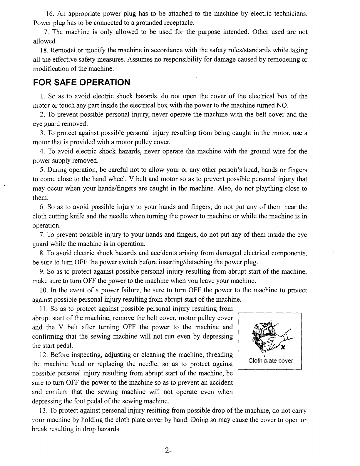
SAFETY
DEVICE
NOTE:
Safety devices herein described may differ m accordance with the destination and
specifications.
Eye guard cover
A cover to prevent the injury to the
eyes, the head or the like due
dispersion
broken needle
~-------------------------------
Finger guard
A cover to prevent the injury due
to the contact
needle.
of
fingers with the
Finger guard
of
to
components such
the
as
the
Safety label
Cautions on safety are
described
I
A cover to prevent the hands, the
fingers and the clothes from being
caught with V belt.
Belt cover
Cloth plate, Cloth plate cover
Covers to prevent the injury to the
hands , the fingers and hair
head, and the damage to the clothes
by
being caught with the
rotating shafts.
of
the
Caution label for the injury to the fingers
Do not allow your hands, fingers, etc.
to come close to the knife to prevent
the injury caused by the knife.
Looper cover
A cover to prevent the injury due
of
to the contact
With the thread take-up lever.
hands and fingers
-3-
Page 5
CONTENTS
I . SPECIFICATIONS
11.
INSTALLATION
1.
INSTALLING THE FRAME
2.
ATTACHING THE BELT COVER
3.
INSTALLING THE PEDALS
Ill.
PREPARATION AND OPERATION
1.
LUBRICATION
2.
CHECKING THE DIRECTION OF ROTATION
3.
THREADING THE MACHINE
4.
ATTACHING NEEDLES
5.
ADJUSTING THE PRESSUER OF THE PRESSER FOOT
ANE REMOVING THE PRESSER FOOT
6.
ADJUSTING THE STITCH LENGTH
7.
ADJUSTING THE DIFFERENTIAL FEED
IV.
MAINTENANCE
1.
ADJUSTING THE KNIVES AND OVEREDGE WIDTH
2.
CLEANING THE MACHINE HEAD
3.
CLEANING
4.
MOTOR PULLEY AND V BELT
5.
DIMENSIONS USED TO ADJUST THE LOOPER
AND THE NEEDLE GUARD
6.
DIMESIONS RELATED TO THE POSITION
OF
THE THREAD TAKE-UP AND THE LOOPER
THREAD
7.
CONVERSION TABLE OF THE NEEDLE NUMBER
CAM
........................................................................
...........................................................................
SUPPORf
.........................................................
...........................................................................
.......................................................
...............................................................
........................................................................
THE
FILTER
(STANDARD ADJUSTMENT)
AND
PUMP
....................................................
.......................................................
PLATE
...................................................
....................................................
...........................................
...............................................
........................................
................................................
NET
......................................
...................................
...................................
........................
.................................
..........................
5
5
5
6
6
6
7
7
7
8
9
9
9
10
1 0
.11
ll
11
11
13
14
-4-
Page 6

1 . SPECIFICATIONS
GM288-3
Sewing speed
(Excluding some subclass models)
Stitch length
Needle gauge
Overedge width
Differential feed ratio Gathering stitch 1:1.9 (Max. 1
Needle
Presser foot lift
Lubricating oil No.32 For special purposes Oil
Noise Workplace-related noise at sewing speed n=5,000 min-1
II.
INSTALLATION
1.
INSTALLING THE FRAME SUPPORT PLATE
(
1)
Semi-sunken type
1)
Attach rubber cushion®to frame support
2)
Attach support plate washer®, support plate bolt spacer@, frame support plateCDand
support plate
to the machine table with support plate bolt A@and
3)
Install waste chute opening(f)on the front side
waste chute(upper)@on the bottom face
4) Install waste chute (lower)®on waste chute(upper)@.
The installation
washer®in
of
the chutes can be adjusted within a length
the written order to the machine table . Then fix the frame support plate
1.0-3.6 mm 1.5-3.6 mm
4.0mm
DCX27
Noise measurement according to DIN 45635-48-A-1.
of
the
table.
GM288-4
I
Max. 6,500 rpm
I
( Standard
Excluding some subclass models
plateCD.
2.0mm
:2.
9) Stretching stitch 1:0.8 (Max. 1 :0.6)
6.5mm
nut®.
of
the upper surface
I
) DC X 1 may be used .
of
of
48 mm.
GM288-5
3.2, 4.8 mm
4.0, 4.8, 6.4 mm
:LPA::::;
the
table,
83
and install
dB(A)
r
b2
r-----1-----.
~~~:;;=~~
3
~/
(
2)
Fully-sunken type
1)
Attach frame support plate joint A@, frame support plate
frame support
2) Fix support plate bolt B@to the machine table .
3)
Put frame support plate joint A@and frame support plate joint B@between support plate
washers®respectively.
Install frame support plate
plateCD.
CD
so that the cloth plate is 5 mm higher than the upper surface
-5-
Table
joint®and
rubber cushion®to
Page 7

ofthe
machine table .
4) Install waste chute stopper
plate.
5)
Install waste chute(upper)(f)on waste chute stopper
®.
plate
6)
Install waste chute(lower)@on waste chute (upper)
(f).
The installation
a length
of
5
48 mm.
of
the chutes can be adjusted within
plate®on
frame support
2. ATTACHING
To
protect against possible personal injury due
of
the Machine,
power
off
and ascertaining that the motor is at rest.
Attach belt coverCDto the machine head .
3.
INSTALLING
To
protect against possible personal injury due to abrupt start
the following work after turning the power
1)
Install starting pedalCDon the left and presser lifter pedal@on the right as seen from the
operator.
2)
Use an S-shaped hook@to connect
the top end
of
presser lifting lever@.
THE
be
sure to start the following work after turning the
THE
BELT
COVER
PEDALS
to
abrupt start
off
and ascertaining that the motor is at rest.
chain®of
the presser lifter pedal to the hole located in
5
3
of
the machine, be sure to start
ill. PREPARATION AND OPERATION
To
avoid malfunction and damage
1)
Before you put the machine into operation for the first time after set-up, clean it
of
the machine, confirm the following:
-6-
Page 8

thoroughly.
2) Remove all dust gathering during transportatfon and oil it well.
3)
Confirm that the voltage has been correctly set.
4) Confirm that the voltage has been correctly connected to the power supply.
5) Never use the machine in the state where the voltage type is different from the designated one.
1.
LUBRICATION
To
protect against possible personal injury due to abrupt
of
start
turning the power off and ascertaining that the motor is at rest.
red marker lines when oil gauge®is observed from the side .
the machine, be sure to start the following work after
1)
Remove oil
2) Pour
3)
N0.32
Supply oil until the oil surface reaches between the two 2
capCD.
for special purposes oil reservoir.
.----6~....-i-..llf'l
Note:
1)
Be careful not to supply oil above the upper red marker
line, or else troubles due to excessive lubrication may result.
of
2) Change oil when one month has passed after the setup
change oil every six months.
3)
Supply oil
oil gauge from the side.
if
the oil surface comes down under the lower marker line when observing the
the sewing machine. Then,
Note:
Apply two or three drops
operating the machine for the first time after set-up or
of
oil
to
the needle bar and upper looper guide portion when
after a long period
2. CHECKING THE DIRECTION OF ROTATION
1)
The correct direction
clockwise when observing the machine from the handwheel side.
Never allow the machine to rotate in the reverse direction.
If
the machine rotates counterclockwise, the oil pump will fail to
function resulting in seizure.
of
rotation
of
the sewing machine is
3. THREADING THE MACHINE
To
protect against possible personal injury due to abrupt start
the following work after turning the power
Thread the machine
as
shown in the figure. (Threading diagram is pasted inside the looper
off
and ascertaining that the motor is at rest.
-7-
of
disuse.
of
the machine, be sure to start
Page 9

cover.)
GM288-4
GM288-5
Note:
Raise looper thread cam thread
guideCD
and perform threading . Return looper
thread cam thread guide
CD
to its home
position and securely fix it to thread guide
spring@.
Intermediate
Thread guide
Note:
Be sure to pass the needle thread for
double chainstitch through the needle
thread take-up lever.
(Pass the needle thread for overlocking
through the thread take-up lever located
outside.)
Note:
When using an untwisted thread such
wooly nylon thread or weak thread,
as
do
not wind it round the intermediate thread
guide.
4. ATTACHING NEEDLES
To
protect against possible personal injury due to abrupt start
the following work after turning the power off and ascertaining that the motor is at rest.
The standard needle is DC
X 27#11 .
You
can also use the DC X 1 needle . In
however, the clearance provided between the needle and the looper may be required to be
If
adjusted.
sewing needs to be carried out with a finely adjusted thread tension , use the DC X 27
needle.
1)
Bring needle clamp(Dup to the highest position .
2) Loosen needle clamp
screw®, and fully insert the needle into the needle clamp hole with the
needle recess facing backward as viewed from the operator's side .
of
the machine, be sure to start
thi~
case,
-8-
Page 10

3)
Tighten needle clamp screw@.
1
GM288-3
5.
ADJUSTING
PRESSER
To
start
of
turning the power
rest.
1)
presser foot adjust
When the adjust screw is turned clockwise, the pressure 3
will increase. When it
pressure will decrease.
2)
lower presser bar lifting lever@.
6.
ADJUSTING
FOOT
protect against possible personal injury due to abrupt
the machine, be sure to start the following work after
Adjust the pressure
To
open presser foot®sideward , raise the needle to the highest position
THE
PRESSURE
off
and ascertaining that the motor is at
of
screweD.
is
turned counterclockwise, the
THE
STITCH
Of'
THE
the presser foot by turning
PRESSER
LENGTH
FOOT
1
GM288-5
AND
REMOVING
of
its stroke and
THE
To
protect against possible personal injury due
to
abrupt start
following work after turning the power
ascertaining that the motor
1)
Slowly turn the hand wheel as you keep
depressing pushbuttonCD, and you will find a point
at which the pushbutton goes in farther .
2)
With the above condition maintained , align the desired scale mark on the handwheel with
mark@on the belt cover. Use the scale mark as reference.
3)
Reset pushbuttonCDafter setting the scale
?.ADJUSTING
To
protect against possible personal injury
due to abrupt
start the following work after turning the power
off
and ascertaining that the motor is at rest.
1)
Loosen differential feed lock
differential feed adjusting lever
stretching stitch or down for gathering stitch .
2)
When you want to move differential feed
adjusting leverCDonly slightly , use differential
of
the machine, be sure to start the
is
at rest.
THE
start
DIFFERENTIAL
of
the machine, be sure to
nut®.
CD
up for
Move
off
and
mark.
FEED
1
_j
-9-
Page 11

feed fine adjustment
3)
When
differential feed ratio
main feed dog and the differential feed dog will be 1:1.
4) The
depending
beyond
IV.
MAINTENANCE
1.
ADJUSTING
To
protect against possible personal injury due to
abrupt start
following
ascertaining that the motor is at rest.
1)
Height
Loosen
lower knifeCDso that its edge is flush with the throat
plate surface .
2) Height
Loosen
that upper knife
to 1
position.
3)
provided by changing the parts
models.
To
the lower knife comes in contact with the upper knife .
mm
Overedge
Overedge widths
(The overedge width will be slightly larger than the knife cut width.)
change the overedge width:
1)
Loosening setscrew@,
2) Loosen
3)
Lower
the scale
maximum
on
the adjustment
"0" are used as reference.
of
the machine, be sure to start the
work
of
the lower knife
setscrew®and
of
the upper knife
setscrew@and
when
width
setscrew@and
the upper knife to its lowest point and loosen setscrew@. Tighten setscrew@when
screw®.
mark
of
THE
after turning the power
@ overlaps lower knifeCDby 0.5
upper
of
is set to "-1 ", the machine will
1 :0.8, and
differential feed ratio for gathering is 1:1.9 (it can be set to 1:2.9
of
when
the internal mechanism
it is set to
KNIVES AND OVEREDGE
off
and
adjust the height
perform adjustment so
knife@
1.6 through 6.4
is at its lowest
mm
are
or
by
using subclass
push
lower knifeCDto the left and fix it .
move upper
knife®as
"0",
of
of
required,
the differential feed ratio between the
the sewing machine). The scale marks
then
perform
WIDTH
fix
it.
stretching stitch with a
4
Note:
1)
Be sure to tighten
2) After the completion
a thread to make sure
setscrew@
of
of
sharpness
before operating machine .
adjustment, make the knives cut
of
the knives.
4) Resharpening the lower knife
When
shown in the figure right.
the lower knife has become dull, resharpen it as
-10-
Page 12

2.
CLEANING
To
protect against possible personal injury due to abrupt start
the following work after turning the power
Clear lint from inside the looper cover and the needle bar and components about one or twice
a
day.
If
not, oil may leak or the sewing material will be soiled.
THE
MACHINE
HEAD
of
the machine, be sure to start
off
and ascertaining that the motor is at rest.
Note:
Do not wipe the coated surface
damage the coated surface.
3. CLEANING
1)
To
use the sewing machine for an extended period
time , clean filterCDand pump net®periodically twice or three
times a year .
the machine components may be seized or worn out
extraordinarily. So, carefully check the filter and pump net.
If
the lubricating oil in the machine is stained, change the
2)
oil also at the time
4.
MOTOR
Number
Revolutions
of
machine
(rpm)
of
Sewing
6,500 120
6,000
5,500 100
5,000 90
4,500 80
THE
If
the filter and pump net are clogged with dusts,
of
PULLEY
Outer V belt (inch) Outer
diameter
motor pulley
(mm)
110
FILTER
cleaning.
AND V BELT
50
of
Semi-sunken Fully-sunken
type
of
the machine head with lacquer thinner. Doing so will
AND PUMP NET
Hz
type
38
36
36
35
35
32
32
32
30 80
30 70 34 30
of
diameter
motor
pulley (mm)
100
95
85
60Hz
V belt (inch)
of
Semi-sunken Fully-sunken
type type
36
35
35
34
32
30
30
30
~
__
j
1)
Use a clutch motor
2)
Use an M type V belt.
3)
Relations among number
belt are as shown in the aforementioned table.
4)
Effective diameter
5.
DIMENSIONS USED
of
1/2 HP (400W).
of
ofthe
handwheel
TO
revolutions
of
sewing machine head is 50.6 mm.
ADJUST
of
sewing machine, motor pulley, and length
THE
LOOPER
GUARD
1)
To
protect against possible personal injury due to abrupt start
start the following work after turning the power
2)
To
avoid possible accidents due to unfamiliarity with the machine, get a maintenance man
of
who has a good knowledge
the machine or serviceman
off
and ascertaining that the motor is at rest.
of
our distributor to adjust the machine
-11-
AND
of
THE
the machine, be sure
NEEDLE
of
V
to
Page 13

or replace any
3)
To
avoid possible personal injury when the machine starts, it has to be ascertained in prior
to the actuation
one another.
of
its parts.
of
the machine that
no
screw are loosened and no components come in contact
Note:
The dimensions given in the table are standard ones to be used to adjust the looper. They are
intended to be used for reference and should be changed more or less in Accordance with the
sewing products and thread to be used.
GM288-3
GM288-305
A
GM288-4
F
G
A
GM288-5~
~
cf$$
A B
GM288-3
GM288-305
GM288-4
GM288-5
GM288-3B
GM288-5-60H 12.6 11.1
GM288-6
11
11
11
11
11
11
10.1
10.1 9.5
B
t
A
c
9.5
l
0.05-0.
D
11.8
11.8
11.8
11.8
10.5
12.8
11.8
Blade
e=ss=
2mm
E F
4.8
4.8
4.8
4.8
4.9
4.9
4.9
p~ln
0.05-0.
4
4
4
4
4
3
4
loopec
lmm
G
1.8
1.8
1.8
1)
Adjust the lower
so
looper
pushed by
this side by the blade point
of
lower lopper in the state
where the blade point
lower looper is aligned with
the center
that the needle is
0.05 to 0.1mm to
of
of
needle.
Push needle to this side.
-12-
Clearance provided between
Needle and blade point
Lower looper
of
CD
Page 14

2)
Then,
and the blade point
adjust traveling needle
of
lower looper should be 0 to 0.05mm in the state where the needle
guardCDso
that the clearance provided between the needle
pushed to this side by traveling needle guardeD.
For the 2-needle overlock machine, adjust both the left and
rig~1t
needles in the same manner.
is
Needle
6.
DIMENSIONS RELATED TO THE POSITION OF THE THREAD TAKE-UP
THE
(1) Position
guard
c1M:288-3i305i4
LOOPER
of
the looper
components
THREAD CAM (STANDARD ADJUSTMENT)
thread
take-up lever
(
'\
1288-3
(,\1288-4
CiM288-5
CM288-305 t
CM288-5-50H
GM288-5-60H
GM288-6
and
the looper
A B c
68 25 44.5
t t t t t
t
t t t
t
t
t t
t
t
t
t
t t t
thread
D E F G
22
t t t
t t
t t
t
t t
GM288-5
guide
37 26 9
24 8
26
t t
10
t
H
26 22
8
27 23.5
9
26
26
30 26.5
t
t t t t
27
8
23.5
I
22
19
AND
J K
12
t
t
15
18.5
12
t t
6
t
•t
6
(2) Position
take-up lever
To
protect against possible personal
injury due to abrupt start
be
sure to start the following work after
turnir:g the power
of
and
the
needle
needle
off
thread
of
the machine,
and ascertaining
that the motor is at rest.
A
(
\12XX-3B
1
68.5 24
Dimensions
when the upper looper
thread
Frame
guide
Throat plate surface
c D E
B
-
ofE
and G are adjustment values
Needle thread guide
F
G H l J
43
is
at its rightmost point.
take-up lever
~J/777?77777?
K
H
10
17
6.8
C11v1288-3B
Note:
The needle thread
take-up lever shall be
positioned at the upper
thread dead point
l
J K
20
23.5
35
-13-
Page 15

C
,:,
Needle
Needle thread
Position at which the lower end
of
thread hole
thread guide
edge line
take-up lever
of
IS
aligned with the
of
gu1ae
the needle
t:Jke-up lever
l::'SX-1
thread 1
~05
GM2R8-4
CiM288-5
GM288-6
o:l
..,
~
Chain looper needle
thread
0
e
00
"""
gmde
13mm
Chain looper needle
thread take-up lever
13
mm
Chain looper
needle thread
take-up lever
Note:
The needle thread take-up lever
shall be
positioned at the lower dead point.
(3)
Adjustment
Throat plate
Make sure that the looper thread cam releases the looper thread when
the needle tip
7.
CONVERSION TABLE
r
value for the looper
Interlock needle
is
positioned
±0.5
mm against the botton face
OF
thread
THE
cam (G!\1288-5)
NEEDLE NUMBER
JAPAN (ORGAN)
~--------------------------
DCX27
DCX27
DCX27
--
DCX27
DCX27
DCX27
DCX27
#9
#11
#14 B-27 Nm90
#16
#18
··----
#19
.,
_______
#21
Thread
of
the throat
plate.
GERMAN (SCHMETZ)
B-27 Nm65
B-27 Nm75
B-27
NmlOO
B-27
NmllO
B-27 Nm120
-
B-27 Nm130
--
--
-14--
Page 16

SHANGHAI HUIGONG SEWING MACHINE
ADD:
1418,
Yishan
Zip
Code:
201103
TEL:
(021)64061284
FAX:
(021)64462799
E-mail: Highlead@online.
http://highlead.
Road,
Shanghai, China
64654014
com.
en
sh.
en
N0.3
FACTORY
 Loading...