

Highlead GL13118-1 User Manual
HIGH
LEAD
GL13118-1
Blindstitch machine
Instruction
Manual
Parts Catalog
SHANGHAI HUIGONG
N0.3
SEWING MACHINE FACTORY
I.
Brief Instruction
2.
Main Specification
3.
Installation
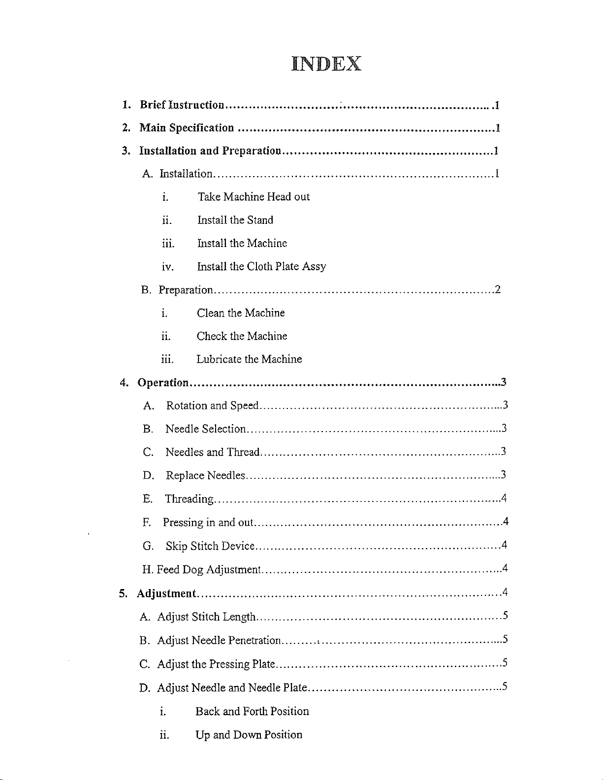
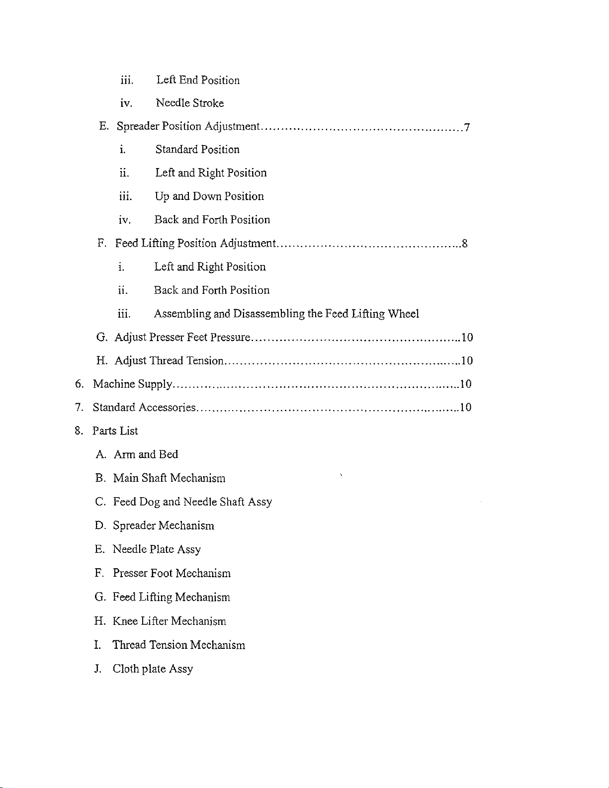
INDEX
............................. ; .......................................
..................................•...............................
and
Preparation
.................•....................................
1
!
1
A. Installation
1. Take Machine Head out
11.
m. Install the Machine
IV. Install the Cloth Plate Assy
B.
Preparation
1.
11.
m. Lubricate the Machine
4.
Operation
A.
B.
C.
........................................................................
Install the Stand
........................................................................
Clean the Machine
Check the Machine
................................................................................
Rotation and Speed
Needle Selection
Needles and Thread
...............................................................
..................................................................
..............................................................
1
2
3
3
3
3
D.
E.
F.
G.
H.
Feed Dog Adjustment..
5.
Adjustment
A.
Adjust Stitch Length
B.
Adjust Needle Penetration
C.
Adjust the Pressing Plate
D.
Adjust Needle and Needle Plate
Replace Needles
Threading
..........................................................................
Pressing in and out..
Skip Stitch Device
..................................................................
.............................................................
..............................................................
...........................................................
.............................................................................
...............................................................
........
..........................................................
1. Back and Forth Position
11. Up and Down Position
·'
...............................................
..................................................
3
.4
.4
.4
.4
.4
5
5
5
5
111.
IV. Needle Stroke
E.
Spreader Position Adjustment
Left End Position
...................................................
7
1.
Standard Position
n. Left and Right Position
111.
1v.
Up and Down Position
Back and Forth Position
F. Feed Lifting Position Adjustment.
1. Left and Right Position
n. Back and Forth Position
111.
G.
Adjust Presser Feet Pressure
H. Adjust Thread Tension
6. Machine Supply
7. Standard Accessories
8.
Parts List
Assembling and Disassembling the Feed Lifting Wheel
............................................................
.........................................................................
...................................................................
..............................................
.....................................................
8
1 0
lO
10
lO
A. Arm and Bed
B.
Main Shaft Mechanism
c.
Feed Dog and Needle Shaft Assy
D.
Spreader Mechanism
E. Needle
F.
Presser Foot Mechanism
G.
Feed Lifting Mechanism
Plate Assy
H. Knee Lifter Mechanism
I. Thread Tension Mechanism
J.
Cloth plate Assy
1.
Briefinstruction
This model is designed with needle bar
mechanism
one arched needle and one spreader. Also it is equipped with regulation mechanism
adjust presser foot pressure, thread tension, stitch length, feed lifting, presser
and feed ratio for blind stitching light
operations, such
It
is requested
for best machine performance.
to
catch thread loop producing Stitch 103 and straight blind stitch seam by
to
medium heavy weight fabrics or sewing
as
trousers cuff, lap, fore pant
to
read this instruction manual carefully before operating the machine,
of
suit, etc.
to
take
up
thread
and
spreader
foot
2. Main Specification
(!)Max. Sewing speed
(2)Max. Stitch length
(3)Feed ratio
(
4)Presser foot lift
(5)Needle
(6)Thread
(7)Motor power
(8)Measurements
(9)Gross weight
2500 r.p.m.
3mm-8mm
1:1
7mm
GLX 1
14.5-7.5 tex cotton
14.8-7.4 tex terylene cotton
270W
510X360
24.5kgs
2:1
NM75-100 (LWX 6T 3#-4#)
X 245
to
left
3. Installation and Preparation
A. Installation
1.
the exposed parts such
Don't dispose
list in order
n. Install the
111.
Take Machine Head out
When taking machine head out
as
thread tension, thread guide etc.
of
any packing material before checking
to
avoid any parts missing.
Stand
a.
First assemble back brace and treadle brace with left and right legs,
then set treadle holders to treadle brace.
b. Install motor onto table.
c.
Set table onto stand with washers and wood screws.
d. Connect motor
position, tighten the nuts for draw bar joint and treadle.
Install the machine
and
treadle lever
of
the packing, be careful not
up
by
draw bars. After adjusting treadle
to
damage
with the packing
a.
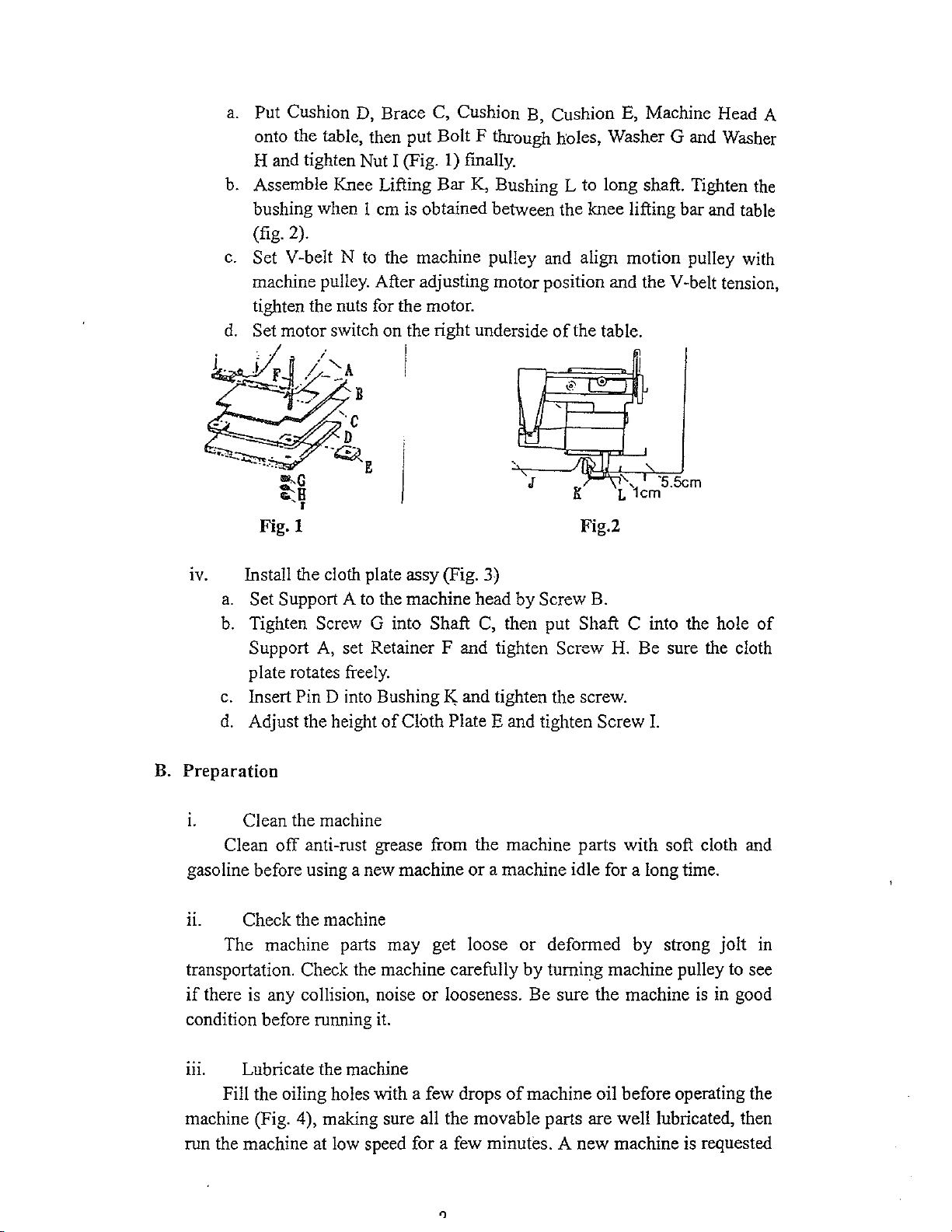
Put Cushion
onto the table, then put Bolt F through holes, Washer G and Washer
H and tighten Nut I (Fig.
b.
Assemble Knee Lifting Bar
bushing when 1 em is obtained between the knee lifting bar and table
(fig. 2).
c.
Set V-belt N
machine pulley. After adjusting motor position and the
tighten the nuts for the motor.
d.
Set motor switch on the right underside
D,
Brace
to
the machine pulley and align motion pulley with
C,
Cushion
1)
B,
Cushion E, Machine Head A
finally.
K,
Bushing L to long shaft. Tighten
V -belt tension,
of
the table.
the
~t~-~:A
-+-~
B
I
'·c
D
--~
E
""G
:--a
'I
Fig. I
IV. Install the cloth plate assy (Fig. 3)
a.
B.
Preparation
Set Support A
b.
Tighten Screw G into Shaft C, then put Shaft C into the hole
Support
plate rotates
c.
Insert Pin D into Bushing
d.
Adjust the height
to
the machine head by Screw
A,
set Retainer F and tighten Screw
freely.
of
Cloth Plate E and tighten Screw I.
,o-
'
'!"""
'
'•
K;
and tighten the screw.
~J
,,_,>'-\1_'-,
Fig.2
["'" l
B.
H.
I
~
I
_,
• '5.5c
L 1cm
Be sure the cloth
m
of
1.
gasoline before using a new machine
n. Check the machine
transportation. Check the machine carefully by turning machine pulley to see
if
condition before
m. Lubricate the machine
machine (Fig. 4), making sure all the movable parts are well lubricated, then
run the machine at
Clean the machine
Clean
The machine parts may get loose or deformed by strong jolt
there
Fill the oiling holes with a few drops
off
anti-rust grease from the machine parts with soft cloth
is
any collision, noise
rum1ing
low
speed for a few minutes. A new machine is requested
it.
or
a machine idle for a long time.
or
looseness. Be sure the machine
of
machine oil before operating the
is
in good
and
in
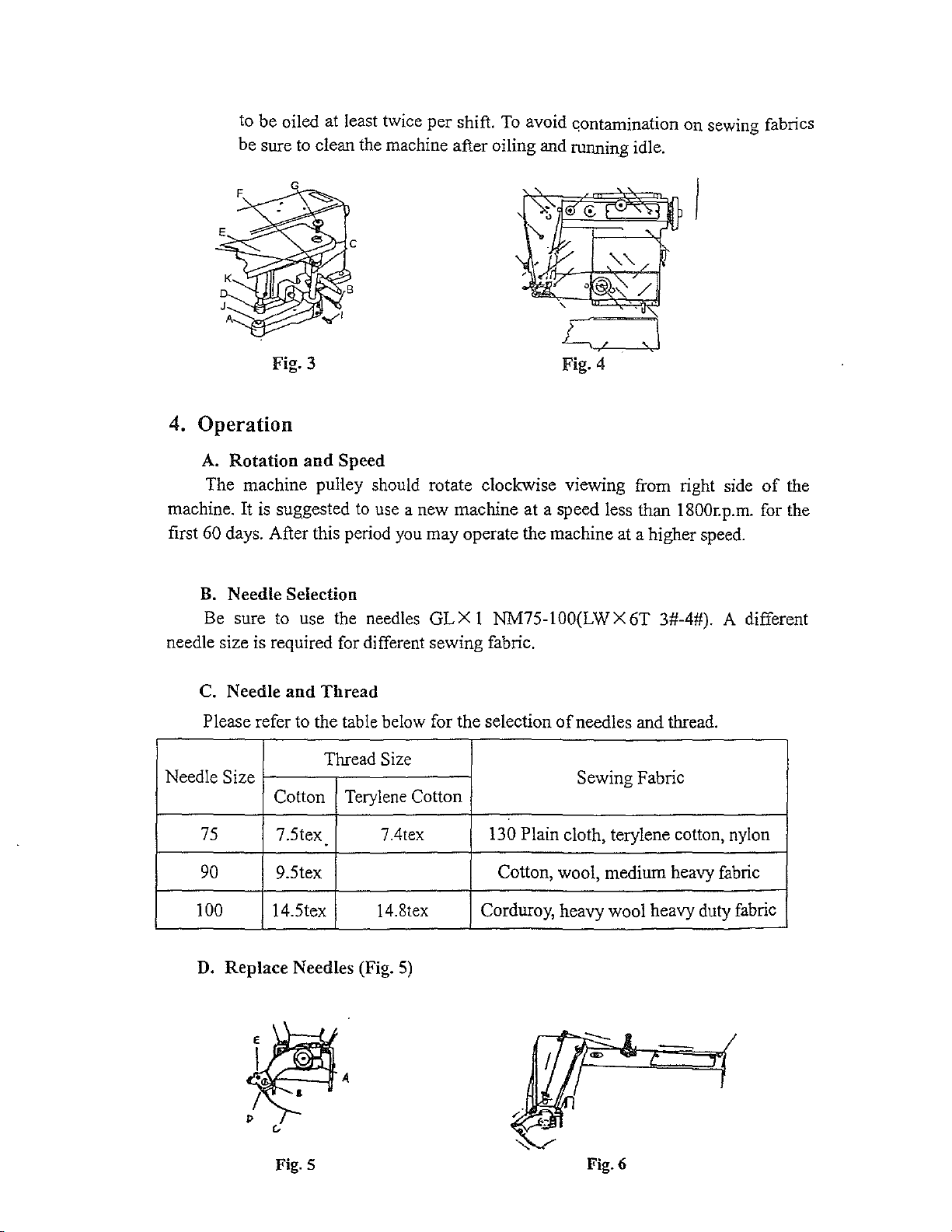
to be oiled at least twice per shift.
be sure to clean the machine after oiling and running idle.
To
avoid c;ontamination on sewing fabrics
C:=J
Fig. 3
4.
Operation
A.
Rotation
The machine pulley should rotate clockwise viewing from right side
machine. It is suggested
first
60 days. After this period you may operate the machine at a higher speed.
and
Speed
to
use a new machine at a speed less than 1800r. p.m. for the
Fig. 4
of
the
B.
Needle Selection
Be sure to use the needles
needle size is required for different sewing fabric.
C. Needle
Please refer to the table below for the selection
Needle Size
75
90
100 14.5tex 14.8tex Corduroy, heavy wool heavy duty fabric
D.
Replace Needles (Fig.
and
Thread
Thread
Cotton
7.5tex 7.4tex 130 Plain cloth, terylene cotton, nylon
9.5tex Cotton, wool, medium heavy fabric
.
Size
Terylene Cotton
GL X 1 NM75-1
5)
OO(LW
of
X 6T 3#-4#). A different
needles and thread.
Sewing Fabric
Fig. 5
-
Fig.6
After turning machine pulley to bring the needle to left end, and adjust the
to
a,
feed lifting dial
one. Make sure the needle shank is
needle plate. Finally tighten Screw B and adjust the feed lifting dial back
the original position. After replacing the needle properly.
needlepoint
sewing performance.
or
loosen Screw B and replace the old needle with a new
in
the needle
the center
is
bent or blunt; you must replace it for proper
of
the left guide slot
If
there
of
is
a bar on
the
to
Threading
E.
Tum the machine pulley
machine
Presser Foot B and Feed Lifting Wheel C, then insert sewing fabric under Needle
Plate
lifter.
back the machine pulley
be taken out easily when lowering the presser foot by knee.
as
shown in the figure.
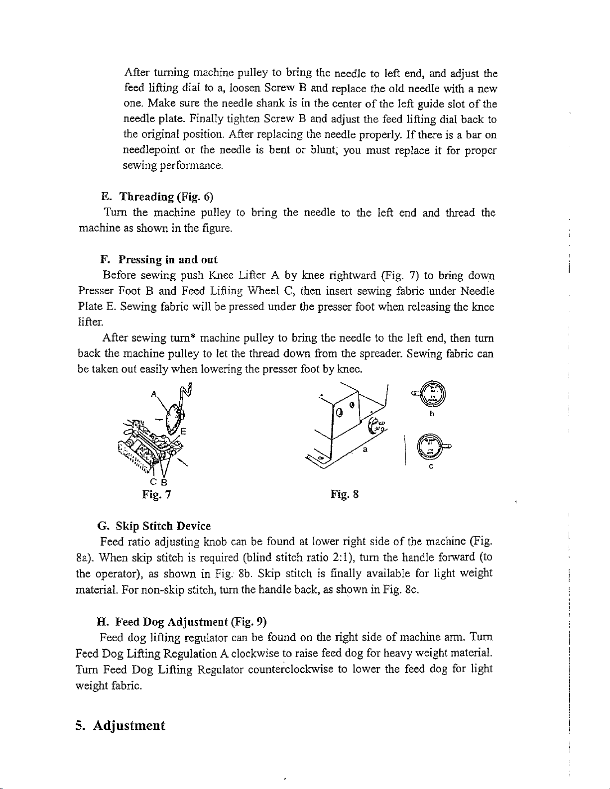
F.
Pressing in
Before sewing push Knee Lifter A
E.
Sewing fabric will be pressed under the presser foot when releasing the knee
After sewing tum* machine pulley to bring the needle to the left end, then tum
Fig. 7
CB
(Fig.
and
6)
to
bring the needle
out
by
knee rightward (Fig.
to
let
the thread down from the spreader. Sewing fabric can
to
the left end and thread the
7)
to bring down
Fig. 8
G.
Skip Stitch Device
at
Feed ratio adjusting knob can be found
8a). When skip stitch is required (blind stitch ratio
Fig.
8b.
the operator), as shown in
material. For non-skip stitch, tum the handle back, as shown in Fig. 8c.
H.
Feed Dog Adjustment (Fig. 9)
Feed dog lifting regulator can be found on the right side
Feed Dog Lifting Regulation A clockwise to raise feed dog for heavy weight material.
Tum Feed Dog Lifting Regulator counterclockwise to lower the feed dog for light
weight fabric.
5.
Adjustment
Skip stitch
lower right side
2:1
),
tum the handle forward (to
is
finally available for light weight
of
the machine (Fig.
of
machine arm. Tum
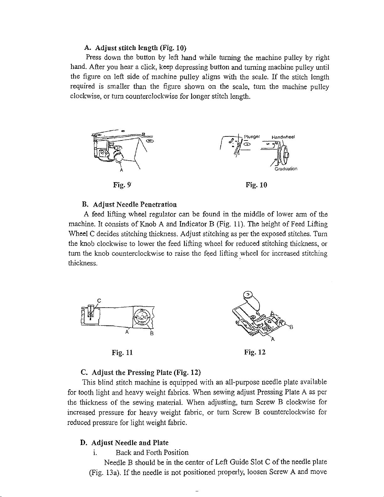
A.
Adjust stitch length (Fig. 10)
Press down the button
hand. After you hear a click, keep depressing button
the figure
required
clockwise, or tum counterclockwise for longer stitch length.
on
left side
is
smaller than the figure shown on the scale, tum the machine pulley
by
left hand while turning the machine pulley by right
and
turning machine pulley until
of
machine pulley aligns with the scale.
If
the stitch length
r~tc;;--~·
Graduation
Fig. 9 Fig. 10
B. Adjust Needle Penetration
A feed lifting wheel regulator can be found in the middle
of
machine. It consists
Wheel C decides stitching thickness. Adjust stitching
the knob clockwise to lower the feed lifting wheel for reduced stitching thickness, or
tum the knob counterclockwise
thickness.
Knob A
and
Indicator B (Fig.
to
raise the feed lifting wheel for increased stitching
11
). The height
as
per the exposed stitches. Tum
of
lower
of
arm
Feed
of
the
Lifting
11
Fig.
C. Adjust the
This blind stitch machine
for tooth light and heavy weight fabrics. When sewing adjust
the thickness
increased pressure for heavy weight fabric, or tum
reduced pressure for light weight fabric.
D.
Adjust Needle
1.
Needle B should be in the center
(Fig. 13a).
Pressing Plate (Fig. 12)
is
equipped with
of
the sewing material. When adjusting, tum Screw B clockwise for
and
Plate
Back and Forth Position
If
the needle
is
not positioned properly, loosen Screw A
an
all-purpose needle plate available
of
Left Guide Slot C
Fig. 12
Pressing Plate A
Screw B counterclod.-wise
of
the needle plate
and
as
move
per
for
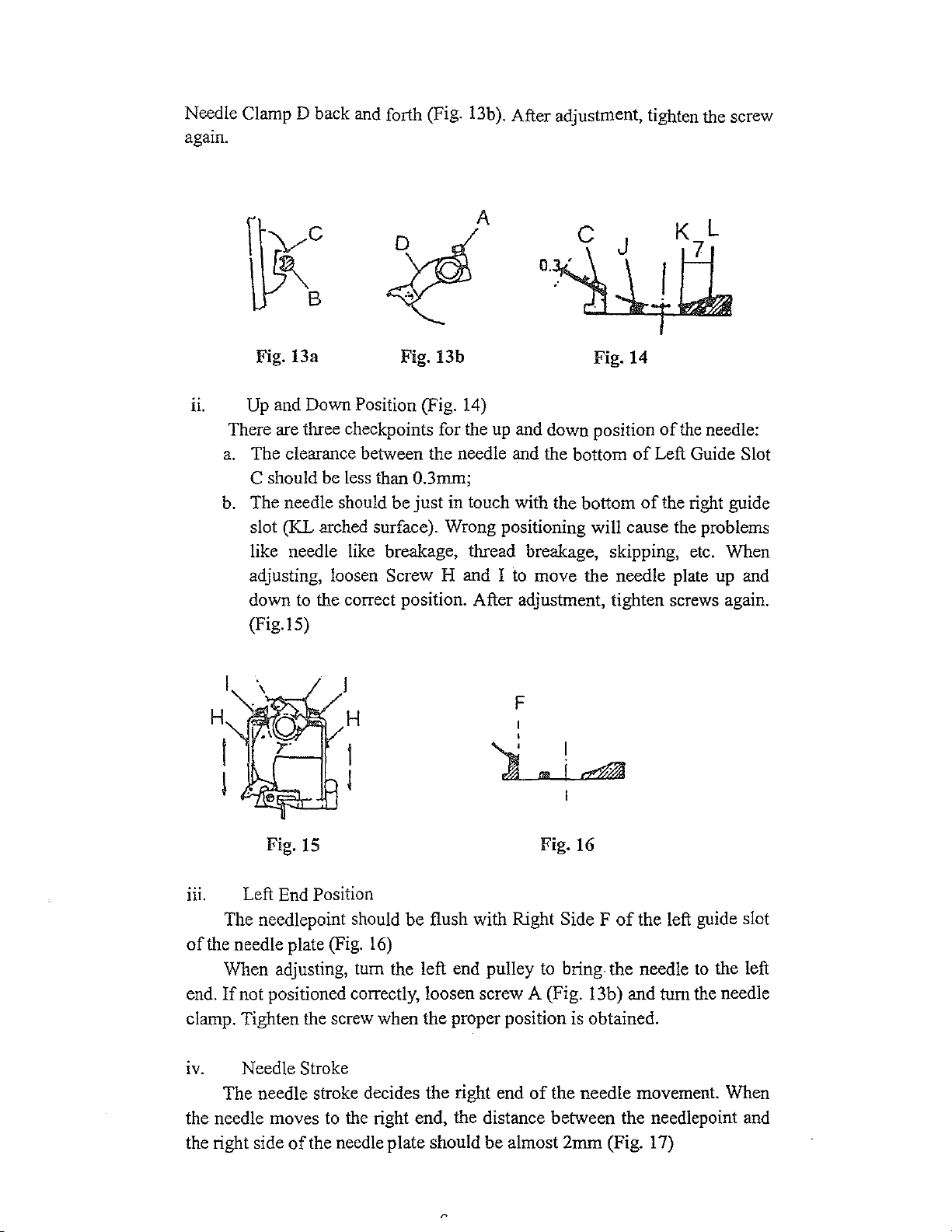
Needle Clamp D back
gam.
a
and
forth (Fig. l3b
).
After adjustment, tighten the screw
A
Fig. 13a
u.
Up
and Down Position (Fig.
There are three checkpoints for the
a.
The clearance between the needle and the bottom
C should be less than 0.3mm;
b.
The needle should be just in touch with the bottom
slot (KL arched surface). Wrong positioning
like needle like breakage, thread breakage, skipping,
adjusting, loosen
down
(Fig. IS)
H
to
the correct position. After adjustment, tighten screws again.
H
Fig. 13b
Screw H and I
I
l
14)
Fig. 14
up
and down position
will cause the problems
to
move the needle plate up and
F
I
•
l
I
..
i~
of
of
Left Guide Slot
of
the right guide
the needle:
etc.
Wben
Fig.
15
nr.
of
end.
clamp. Tighten the screw when the proper position is obtained.
IV. Needle Stroke
the needle moves
the right side
Left End Position
The needlepoint should be flush with Right
the needle plate (Fig.
When adjusting, tum the left end pulley
If
not positioned correctly, loosen screw A (Fig. 13b) and turn the needle
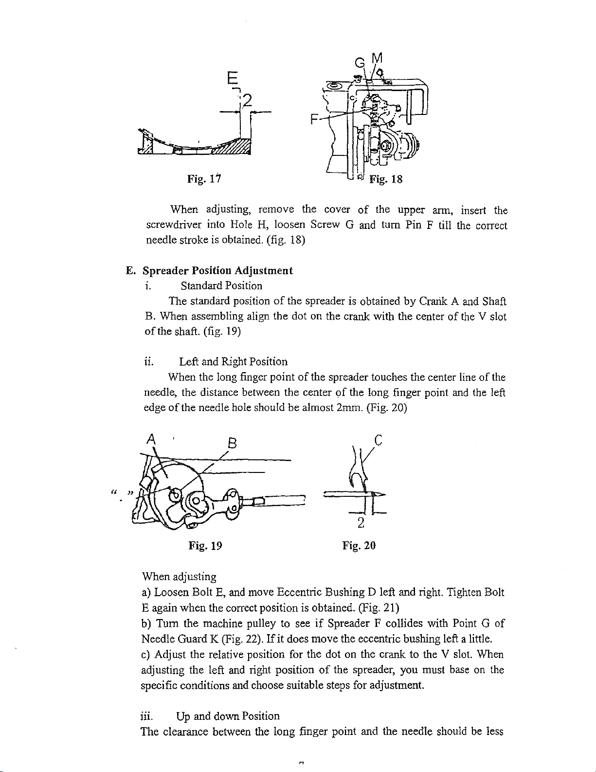
The needle stroke decides the right end
of
the needle plate should be almost 2mm (Fig. 17)
16)
to
the right end, the distance between the needlepoint
Fig. 16
Side F
to
bring the needle
of
the needle movement. Wben
of
the left guide slot
to
the left
and
E
.
j
e
..,
'2_
F
Fig. 17
When adjusting, remove the cover
screwdriver into Hole H, loosen Screw G and turn Pin F till the correct
needle stroke is obtained. (fig. 18)
E.
Spreader
1. Standard Position
B. When assembling align the dot on the crank with the center
of
the shaft. (fig.
11.
needle, the distance between the center
edge
Position
standard position
The
Left and Right Position
When the long finger point
of
the needle hole should be almost 2mm. (Fig. 20)
Adjustment
19)
of
the spreader is obtained
of
the spreader touches the center line
of
A
Fig. 18
of
the upper arm, insert the
by
Crarik A and Shaft
of
the V slot
the long finger point and the left
c
of
the
Fig. 19 Fig. 20
When adjusting
E,
a) Loosen Bolt
E again when the correct position is obtained. (Fig. 21)
b) Turn the machine pulley to see
Needle Guard K (Fig. 22).
c)
Adjust the relative position for the dot on the crarik to the V slot. When
adjusting the left and right position
specific conditions and choose suitable steps for adjustment.
111.
The clearance between the long finger point and the needle should be
Up
and down Position
and move Eccentric Bushing D left and right. Tighten Bolt
if
Spreader F collides with Point G
If
it does move the eccentric bushing left a little.
of
the spreader, you must base on the
2
of
Jess

than 0.05mm when crossing (Fig. 20).
·F
G
Fig. 21
When
a) Loosen
obtained
adjusting
BoltE
with
the spreader
(Fig. 21)
and
at
the
Fig. 23 Fig. 24
b) After adjustment, make
of
opening
tv.
Adjust
a.
spreader C with
Back
and Forth Position
the
back and forth position as follows:
Adjust the position
slot
of
the shaft (Fig. 19).
b. Loosen Nut F and
sure
the
of
Screw
position.
If
the above adjustment still cannot
move
clearance between the front
be
the
spreader slightly
less than 0.5mm.
back
edge
Fig.
22
tum
Eccentric Bushing D till the clearance is
right end.
G
the
needlepoint should
spreader at
the
dot point
come
or
forth for optimum position. Be sure the
of
the
the
left end (Fig. 23)
on
the
H and
tum
to satisfaction, loosen screw K and
spreader sha:ft and Spreader C should
be
in the center
crank in relation to
the
spreader to adjust the
of
the
the
V
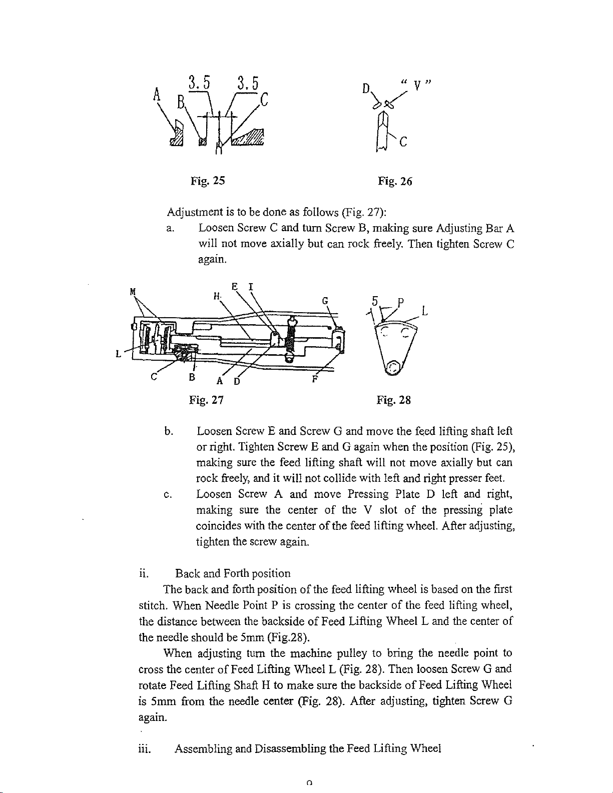
F. Feed Lifting Position Adjustment
1.
the V slot
Left and Right Position
The
center
of
of
Feed Lifting
the
pressing plate (Fig. 25 & 26).
Wheel
R
C should coincide with the center
of
D
"V"
),~
~c
L
Fig. 25
Adjustment is to be done as follows (Fig. 27):
a.
Loosen Screw C and turn Screw B, making sure Adjusting Bar A
will not move axially but can rock freely. Then tighten Screw C
agam.
Fig. 26
L
Fig. 27 Fig. 28
b. Loosen Screw E and Screw G and move the feed lifting shaft left
or
right. Tighten Screw E and G again when the position (Fig. 25),
making sure the feed lifting shaft will not move axially but can
rock freely, and it will not collide with left and right presser feet.
c.
Loosen Screw A and move Pressing Plate D left and right,
of
making sure the center
coincides with the center
tighten the screw again.
the V slot
of
the feed lifting wheel. After adjusting,
of
the pressing plate
11.
stitch. When Needle
the distance between the backside
the needle should be 5mm (Fig.28).
cross the center
rotate Feed Lifting Shaft H to make sure the backside
is
again.
m. Assembling and Disassembling the Feed Lifting Wheel
Back and Forth position
of
The back and forth position
Point P is crossing the center
When adjusting tum the machine pulley to bring the needle point to
of
Feed Lifting Wheel L (Fig. 28). Then loosen Screw G and
5mm
from the needle center (Fig. 28). After adjusting, tighten Screw G
the feed lifting wheel is based on the first
of
Feed Lifting Wheel L and the center
()
of
the feed lifting wheel,
of
Feed Lifting Wheel
of
 Loading...