

Highlead GK31058 User Manual
HIGH
LEAD
GK31058 SERIES
Fiatbed Interlock Stitch High-Speed Sewing Machine
Instruction Manual
Parts
SHANGHAI HUIGONG
N0.3
Catalog
SEWING MACHINE FACTORY

CONTENTS
1,
Introduction----------------------------------------------------------------------------------------------------------------- 1
2,
Mode and Specification--------------------------------------------------------------------------------------------------- 1
3,
Installation------------------------------------------------------------------------------------------------------------------ 1
4,
Sewing Speed and Setting up
5,
Lubrication ----------------------------------------------------------------------------------------------------------------- 2
5-1 Oil to
5-2
5-3 Oil Sight Gauge and Check Procedure
5-4
5-5 Cleaning
6,
6-1
6-2 Threading------------------------------------------------------------------------------------------------------------------ 4
6-3
6-4 Thread Tension------------------------------------------------------------------------------------------------------------4
6-5 Pressure
6-6 Adjusting
6-7 Adjusting
7,
7-1
7-2 Adjusting
7-3 Adjusting
7-4
7-5
7-6 Remove and Fitting
7-7 Relation
7-8 Fitting Angle and Height
7-9 Distance (M) Between Needle and Looper ---------------------------------------------------------------------------- 8
7-10
7-11
7-12 Relative Postioning
7-13 Adjusting
7-14 Adjusting
7-15
7-16 Paralleling
7-17 Fitting
7-18 Fitting
7-19 Fitting
7-20 Adjusting
7-21 Exchange
8,
Parts book---------------------------------------------------------------------------------------------------------------
be
Used-------------------------------------------------------------------------------------------------------------2
Feeding
Exchange
Proper Operation-----------------------------------------------------------------------------------------------------------3
Needles to Be Used, Fitting
Operation
Proper Adjusting
Tension
Adjusting
Positioning
of
of
ofN
ofN
Adjusting
Timing
Height
ofN
of
of
of
of
Oil-------------------------------------------------------------------------------------------------------------2
of
Oil-----------------------------------------------------------------------------------------------------------3
of
Filter and Screen-------------------------------------------------------------------------------------------- 4
of
Spring-out Type Bobbin Thread Guide
Presser Foot and Its Adjustment---------------------------------------------------------------------------5
of
Stitch Length----------------------------------------------------------------------------------------------- 5
of
Differential Feeding--------------------------------------------------------------------------------------6
of
Machine ---------------------------------------------------------------------------------------------6
eedle Thread------------------------------------------------------------------------------------------------ 6
of
Needle Thread Upper Eyelet-----------------------------------------------------------------------------6
of
Ornamental Thread----------------------------------------------------------------------------------------6
of
Looper Thread ---------------------------------------------------------------------------------------------7
of
Looper Thread Take-up Cam---------------------------------------------------------------------------7
of
eedle and stitch plate -------------------------------------------------------------------------------------8
ofN
eedle Bar------------------------------------------------------------------------------------------------8
eedle With Looper Moving Right/Left------------------------------------------------------------------8
of
ofN
eedle Guard(Rear) ------------------------------------------------------------------------------------9
ofN
eedle Guard(Front) -----------------------------------------------------------------------------------9
Feed
Dog
ofF
eed Dog With Stitch Plate ----------------------------------------------------------------------------9
Ornamental Looper and Its Adjusting ------------------------------------------------------------------Ornamental Thread Guide -------------------------------------------------------------------------------- 10
Ornarnental Thread Eyelet ------------------------------------------------------------------------------
of
Swing Scope
of
Upper Shaft Driving Belt -------------------------------------------------------------------------- 10
of
Pulley
---------------------------------------------------------------------------------2
of
Oil Cycling-------------------------------------------------------------- 3
of
Needles; Needle Thread and Needle Device---------------------------------------3
-----------------------------------------------------------------4
Presser Foot and Its Height------------------------------------------------------------------- 7
of
Looper ------------------------------------------------------------------------------------ 8
Needle and Looper in Front/Rear----------------------------------------------------------- 8
-----------------------------------------------------------------------------------------------------9
of
Ornamental Looper-------------------------------------------------------------- 10
10
10
12
1.
Introduction
Model GK31058 Interlock stitch sewing machine is a Special equipment suitable for trades
clothing, and underwear, etc. This series
stitch, loop type interlock stitch, fell interlock stitch, collar and band binding stitch, ornamental stitch which are even,
attractive, decorative, elastic and can be met demands
of
trousers waist, underclothes, underpants, front
be used as different industrial sewing machines
2.
Specifications
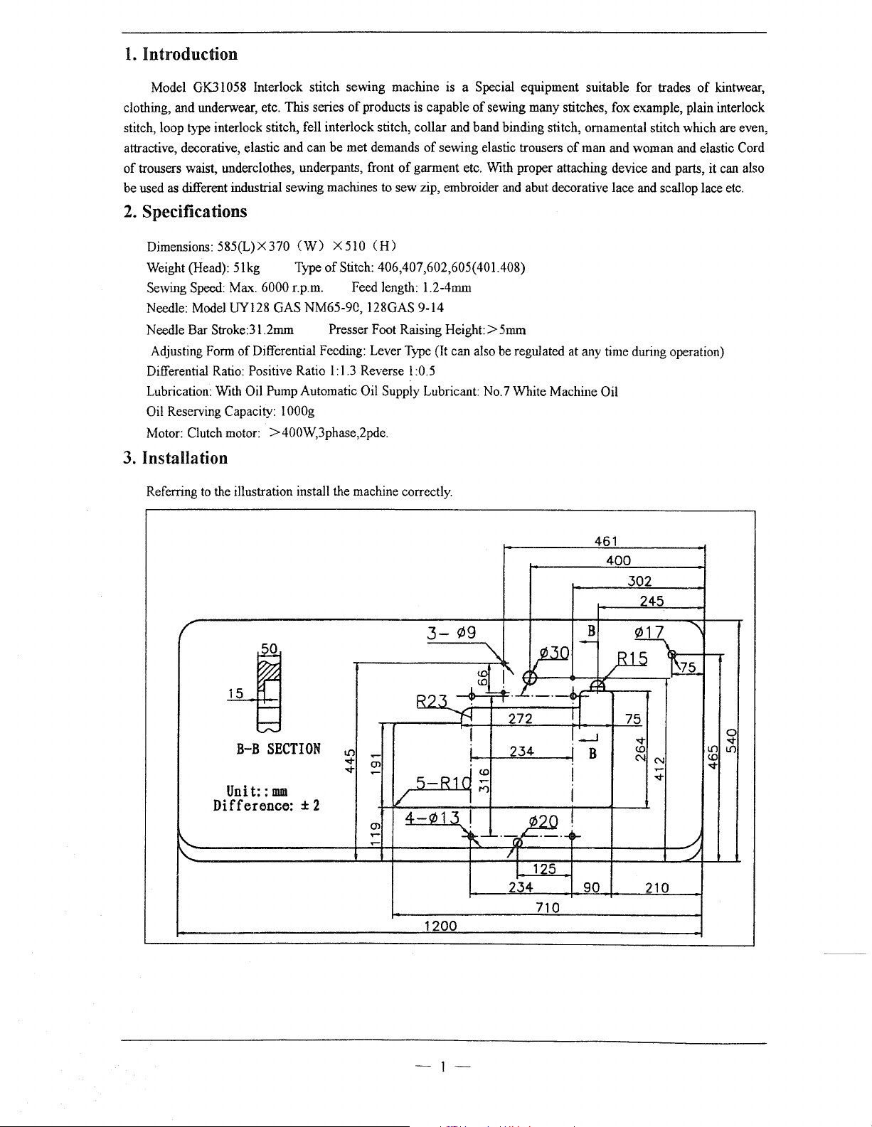
Dimensions:
Weight (Head):
Sewing Speed:
Needle: Model UY128
Needle Bar Stroke:31.2mm Presser Foot Raising
Adjusting Form
Differential Ratio: Positive Ratio l:
Lubrication:
Reserving Capacity: l
Oil
Motor: Clutch motor: >400W,3phase,2pde.
3.
Installation
Referring
585(L)X370
5lkg
Ma""<.
of
Differential Feeding: Lever Type (It can also be regulated at any time during operation)
With
Oil Pump Automatic Oil Supply Lubricant: No.7 White Machine Oil
to
the illustration install the machine correctly.
(W)
Type
6000 r.p.m. Feed length: 1.2-4mm
GAS NM65-90, 128GAS 9-14
OOOg
of
products is capable
of
of
garment etc. With proper attaching device and parts, it can also
to sew zip, embroider and abut decorative lace and scallop lace etc.
X510
(H)
of
Stitch: 406,407,602,605(401.408)
1.3
Reverse l :0.5
of
sewing many stitches, fox example, plain interlock
sewing elastic trousers
Height:>
5mm
of
man and woman and elastic Cord
of
kintwear,
461
400
302
245
3-¢9
'\
-
::;:::::
B-B
SECTION
Unit::mm
Difference: ± 2
.------~
f.U.3_
-===::::ff
5-R1d~
/
m
4-¢13
(l--r-4t-!
~
!i
I
I')
I !
~'-----------------+-~~r+-------~~~~----~_
'
I
1200
~
r-
I
.1._.--w
2 n I
234
..
~0~~------~~~----~--https://manualmachine.com//
/I
I 125
234
710
B
(:~)ill
!.
---l
B
¢17
75
~
L()L()
<!)
..q-
0
..q-
I
I
/
90
210
-1-
4.
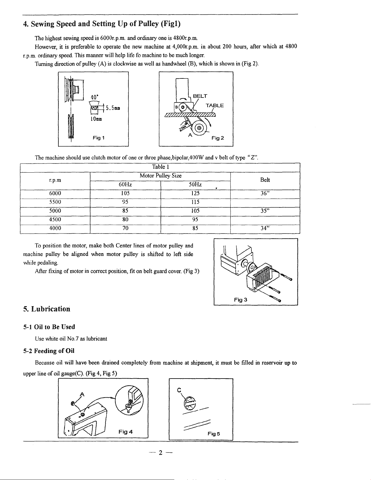
Sewing Speed and Setting Up
The highest sewing speed is 6000r.p.m. and ordinary one is 4800r.p.m.
However, it is preferable to operate the new machine at 4,000r.p.m. in about 200 hours, after which at 4800
r.p.m. ordinary speed. This manner will help life fo machine to be much longer.
of
Turning direction
pulley (A) is clockwise as well as handwheel (B), which is
40'
of
Pulley (Figl)
sho\\11
in (Fig 2).
fJ
~5.5llllll
lOmm
Fig
~
1
The machine should use clutch motor
r.p.m
6000 105
5500 95
5000
4500 80
4000 70
To
position the motor, make both Center lines
machine pulley be aligned when motor pulley is shifted to left side
while pedaling.
of
motor
in
After fixing
5.
Lubrication
5-1
Oil to Be Used
correct position, fit on belt guard cover. (Fig 3)
of
one or three phase,bipolar,400W and v belt
Table I
Motor Pulley Size
60Hz
85
of
motor pulley and
50Hz
125
115
105
95
85
.
of
type
"Z".
Belt
36"
35"
34"
Use white oil No.7 as lubricant
5-2 Feeding
Because oil will have been drained completely from machine at shipment, it must be filled in reservoir up to
upper line
of
Oil
of
oil gauge(C). (Fig 4, Fig
5)
-2-
~
FigS
5-3 Oil Sight Gauge
and
Check
Procedure
of
Oil Cycling.
Check Oil sight gauge everyday before operation and replenish oil
Looking through
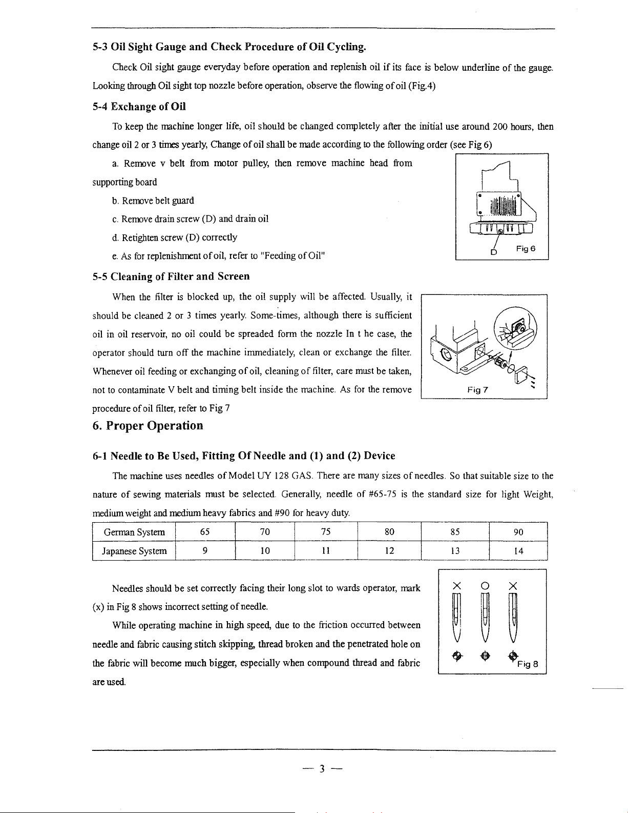
5-4 Exchange
To
keep the machine longer life, oil should be changed completely after the initial use around 200 hours, then
change oil 2 or 3
a.
Remove v belt from motor pulley, then remove machine head from
supporting board
b.
Remove belt guard
c.
Remove drain screw (D) and drain oil
d.
Retighten screw (D) correctly
e.
As
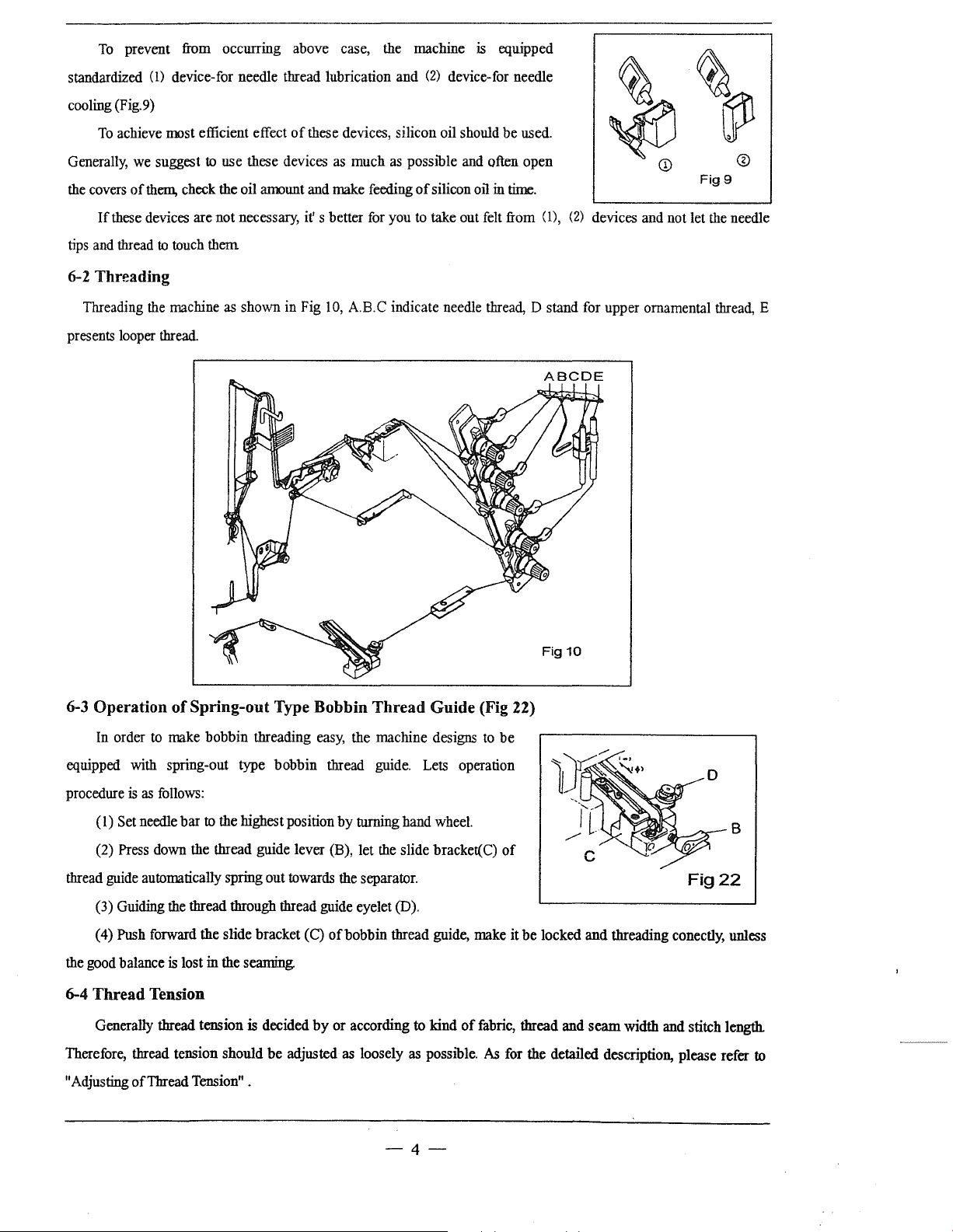
5-5 Cleaning
When the filter
should be cleaned 2 or 3 times yearly. Some-times, although there
oil in oil reservoir, no oil could
operator should turn off the machine immediately, clean or exchange the filter.
Oil sight top nozzle before operation, observe the flowing
of
Oil
times
for
replenishment
of
Filter
yearly, Change
of
and
is
blocked up, the oil supply will
of
oil shall be made according
oil, refer
to
"Feeding
Screen
be
spreaded form the nozzle
of
Oil"
be
affected. Usually, it
In
if
its face is below underline
of
oil (Fig.4)
to
the following order (see Fig 6)
is
sufficient
t he case, the
r-------------~
of
the gauge.
Whenever oil feeding or exchanging
not
to
contaminate V belt and timing belt inside the machine.
procedure
6.
6-1
nature
medium weight and medium heavy fabrics and
Japanese System
(x) in Fig 8 shows incorrect setting
needle and fabric causing stitch skipping,
the fabric will become much bigger, especially when compound thread and fabric
of
oil
filter,
refer
to
Proper Operation
Needle to
The machine uses needles
of
German System
Needles should
While operating machine in high speed, due to the friction occurred between
Be
Used,
Fitting
sewing materials must
65
9
be
set correctly facing their long slot to wards operator, mark
of
oil, cleaning
Fig 7
Of
Needle
of
Model UY 128 GAS. There are many sizes
be
selected. Generally, needle
70
10
of
needle.
thread broken and the penetrated hole
#90
of
filter, care must be taken,
As
for
and
(1)
and
(2) Device
for
heavy duty.
75
11
--.
the remove
of
#65-75
of
is
the standard size for light Weight,
80
12
on
needles.
So
that suitable size
85
13
90
14
to
the
are used.
-3--
To
prevent
from
occurring above case,
the
machine
is
equipped
standardized
cooling (Fig.9)
To
Generally,
the
covers
If
tips
and
(l)
device-for needle thread lubrication and (2) device-for needle
achieve most efficient effect
we
suggest
of
them,
check
these devices are not necessary,
thread
to
touch
6-2 Threading
Threading
presents
looper
the
thread.
machine
to
use these devices
the oil amount
them
as
shown in Fig
of
these devices, silicon oil should be
as
much
as
and
make feeding
it's
better
for
10,
A.B.C indicate needle
possible
you
and
of
silicon oil in
to
take out
used.
often open
time.
felt
from (1), (2) devices
thread,
D stand
ABC
for
DE
Fig9
and
not let
upper ornamental
the
needle
thread,
E
6-3 Operation
In
order
equipped with spring-out type bobbin thread
procedure
(I)
Set
(2)
Press
thread
guide
(3) Guiding
(4)
Push
the
good
balance
6-4
Thread
Generally thread tension
Therefore, thread tension should be adjusted
"Adjusting ofThread
of
Spring-out Type Bobbin
to
make
bobbin threading
is
as
follows:
needle bar
down
automatically spring out towards
forward the slide bracket
to
the
highest position by turning hand
the thread guide lever
the
thread through thread guide eyelet
is
lost in the seaming.
Tension
is
decided
Tension"
.
easy,
the
(B),
the
(C)
of
bobbin thread guide, make it be locked and threading conectly, unless
by
or according
as
Thread
machine designs
guide.
let
the
separator.
loosely
Guide (Fig 22)
Lets
slide bracket(
(D).
to
kind
as
possible.
-4-
operation
wheel.
of
to
be
C)
of
fabric,
thread and seam width
As
for
the detailed description, please refer
Fig22
and
stitch length.
B
to
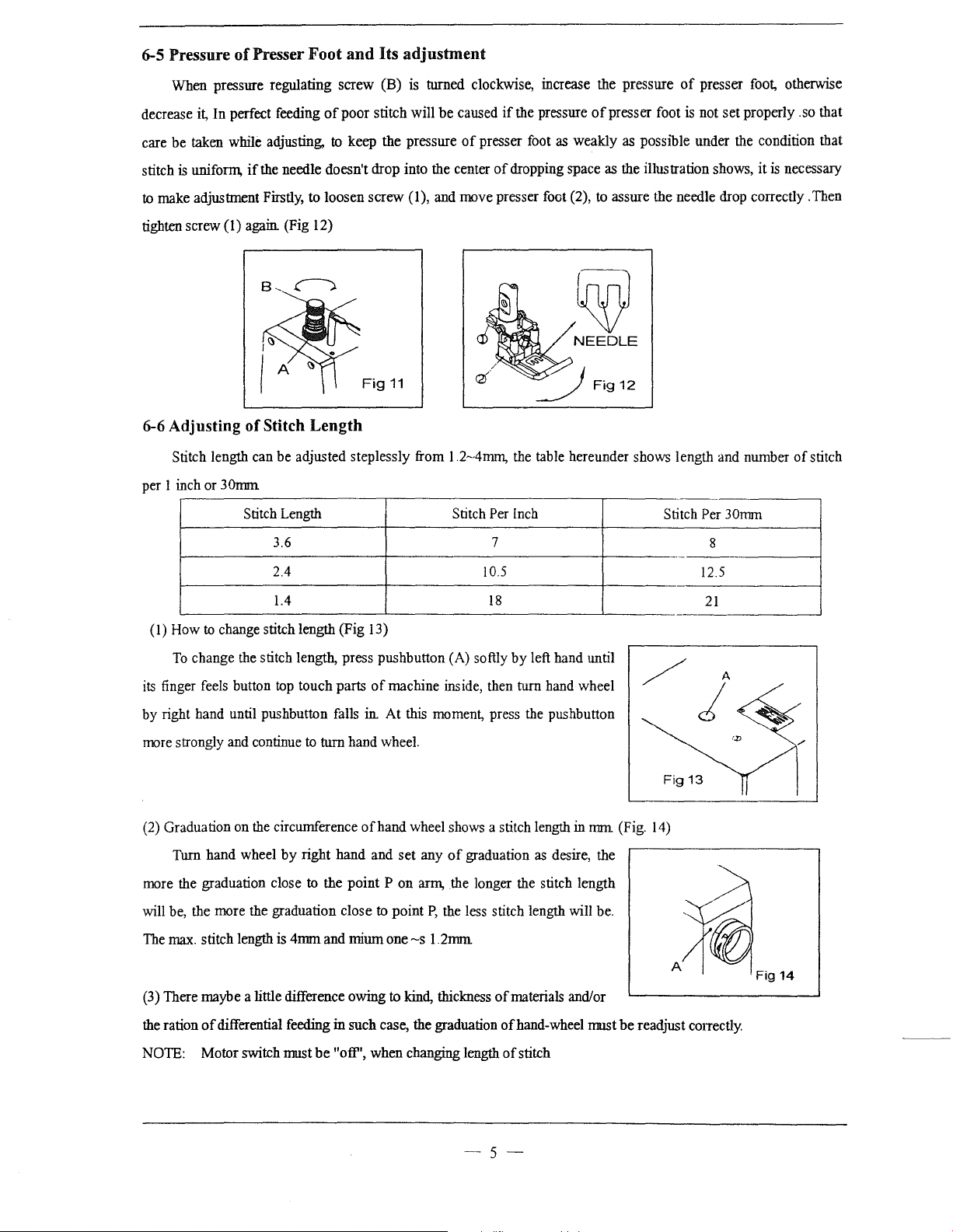
6-5 Pressure
of
Presser Foot
and
Its
adjustment
When pressure regulating
decrease it, In perfect feeding
be
care
stitch
to make adjustment Firstly, to loosen
tighten screw
taken while adjusting,
is
unifonn,
if
the needle doesn't drop into the center
(I)
again. (Fig 12)
screw
ofpoor
to
keep the pressure
6-6 Adjusting of Stitch Length
Stitch length can
per I inch or
30nnn
be
adjusted steplessly from
Stitch Length Stitch Per Inch
(B)
is
turned clockwise, increase the pressure
stitch will
screw
Fig
11
be
caused
if
the pressure
of
presser foot as weakly as possible under the condition that
of
dropping space as the illustration shows,
(1), and move presser foot (2), to assure the needle drop correctly .Then
1.2~4mm,
the table hereunder shows length and number
of
presser foot
NEEDLE
of
presser foot, otherwise
is
not
set
Stitch
Per 30mm
properly .so that
it
is
necessary
of
stitch
3.6 7
2.4 10.5
1.4
(I)
How
to
change stitch length (Fig 13)
To
change the stitch length, press pushbutton (A) softly
of
its finger feels button top touch parts
by
right hand until pushbutton falls in.
more strongly and continue to turn hand wheel.
(2) Graduation on the circumference
Turn
hand
wheel
by
right
hand
more the graduation close to the
will be, the more the graduation close to point
The max. stitch length is
4mm
and miurn one
machine inside, then turn hand wheel
At
this
ofhand
point P on
wheel shows a stitch length in
and
set
~s
18
by
left hand until
moment, press the pushbutton
any
of
graduation as desire, the
arm,
the longer the stitch length
P,
the less stitch length will be.
1.2nnn
nnn
/ A
Fig
(Fig. 14)
8
12.5
21
j
13
(3) There maybe a little difference owing to kind, thickness
of
the ration
NOTE: Motor switch nrust
differential feeding
in
such case, the graduation
be
"oft'',
when
changing length
of
materials and/or
of
hand-wheel nrust
of
stitch
-5-
be
readjust conectly.
6-7 Adjusting
of
the Differential Feed Ratio
The differential Feed Ratio
1:
l.3(Fig. 15)
To
adjust the ratio, loosen the
To
stretch the cloth, move the indicator (1) upward;
To
gather the cloth, move the indicator (1)
7.
Proper
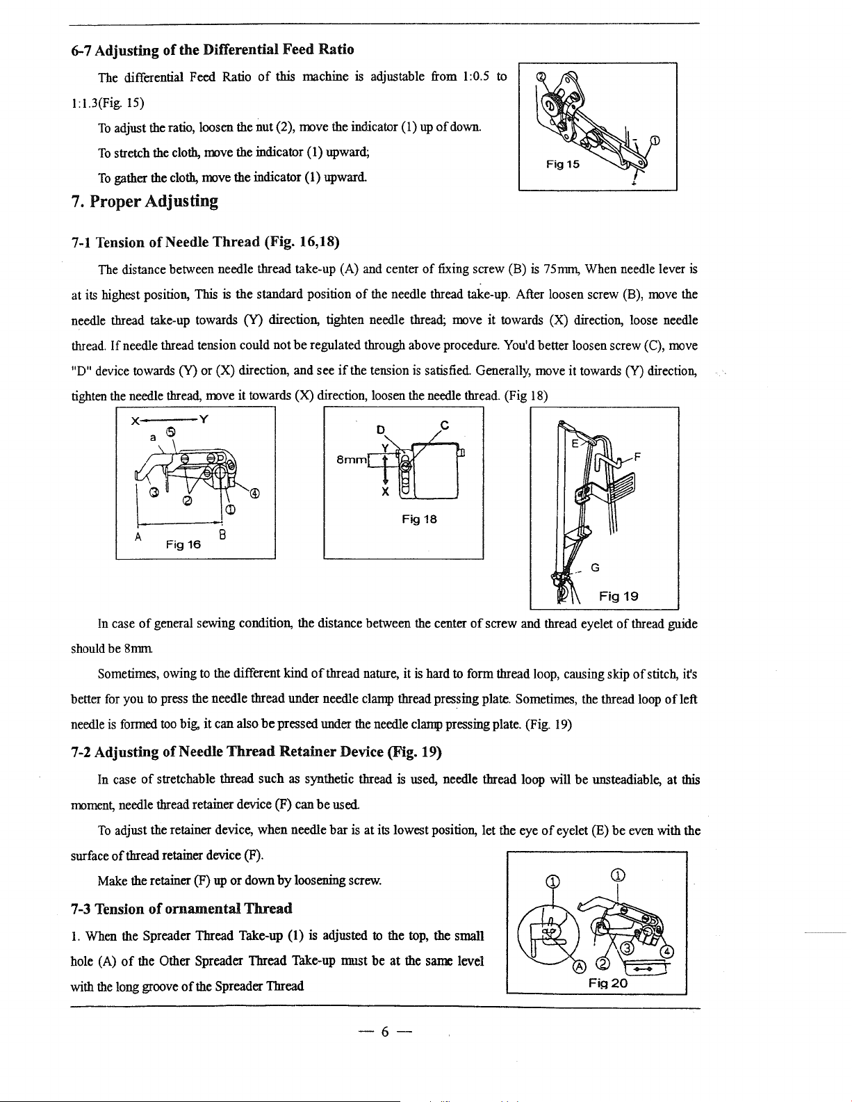
7-1
Tension
The distance between needle thread take-up (A) and center
at
its
highest position,
needle thread take-up towards
thread.
"D" device towards (Y)
tighten the needle thread, move it towards
Adjusting
of
Needle
If
needle thread tension could
Thread
This
or
of
this machine is adjustable from 1:0.5 to
nut
(2), move the indicator (
upward
(Fig. 16,18)
is
the
standard position
(Y) direction, tighten needle thread; move
not
be
regulated through above procedure. You'd better loosen screw (C), move
(X) direction, and
(X) direction, loosen the needle thread. (Fig 18)
see
of
if
the tension
Bmmcf(]
l)
up
of
down.
of
fixing
screw
(B) is 75nnn,
the needle thread take-up. After loosen screw (B), move the
it
towards (X) direction, loose needle
is
satisfied. Generally, move it towards (Y) direction,
When
needle lever
is
.----------------.
In
case
of
general sewing condition, the distance between the center
should
be
8rrnn
Sometimes, owing to the different kind
better for
needle
7-2 Adjusting ofNeedle
moment, needle thread retainer device (F)
surface
7-3 Tension
you
to press the needle thread under needle clamp thread pressing plate. Sometimes, the thread loop
is
formed too big,
In case
To
Make the retainer (F) up
of
stretchable thread
adjust the retainer device,
of
thread retainer device (F).
of
it
can
ornamental
also
be
Thread
such
when
or
down
Thread
pressed under the needle clamp pressing plate. (Fig. 19)
Retainer
by
Fig18
of
screw
and thread eyelet
of
thread nature, it
is
hard to form thread loop, causing skip
Device (Fig. 19)
as synthetic thread is used, needle thread loop will
can
be
used
needle
bar
is
at
its lowest position,
loosening screw.
let
the eye
of
eyelet (E)
of
be
unsteadiable,
be
thread guide
of
stitch, it's
ofleft
at
this
even with the
1.
When the Spreader Thread Take-up (1) is adjusted to the top, the small
of
hole (A)
with the long groove
the Other Spreader Thread Take-up nrust
of
the Spreader Thread
be
at
the same level
-6-
2.
To
adjust, loosen Screw (3) and (4), and move the Spreader Thread Take-up (2)
screw again. (Fig 20)
up
or down, and then tighten
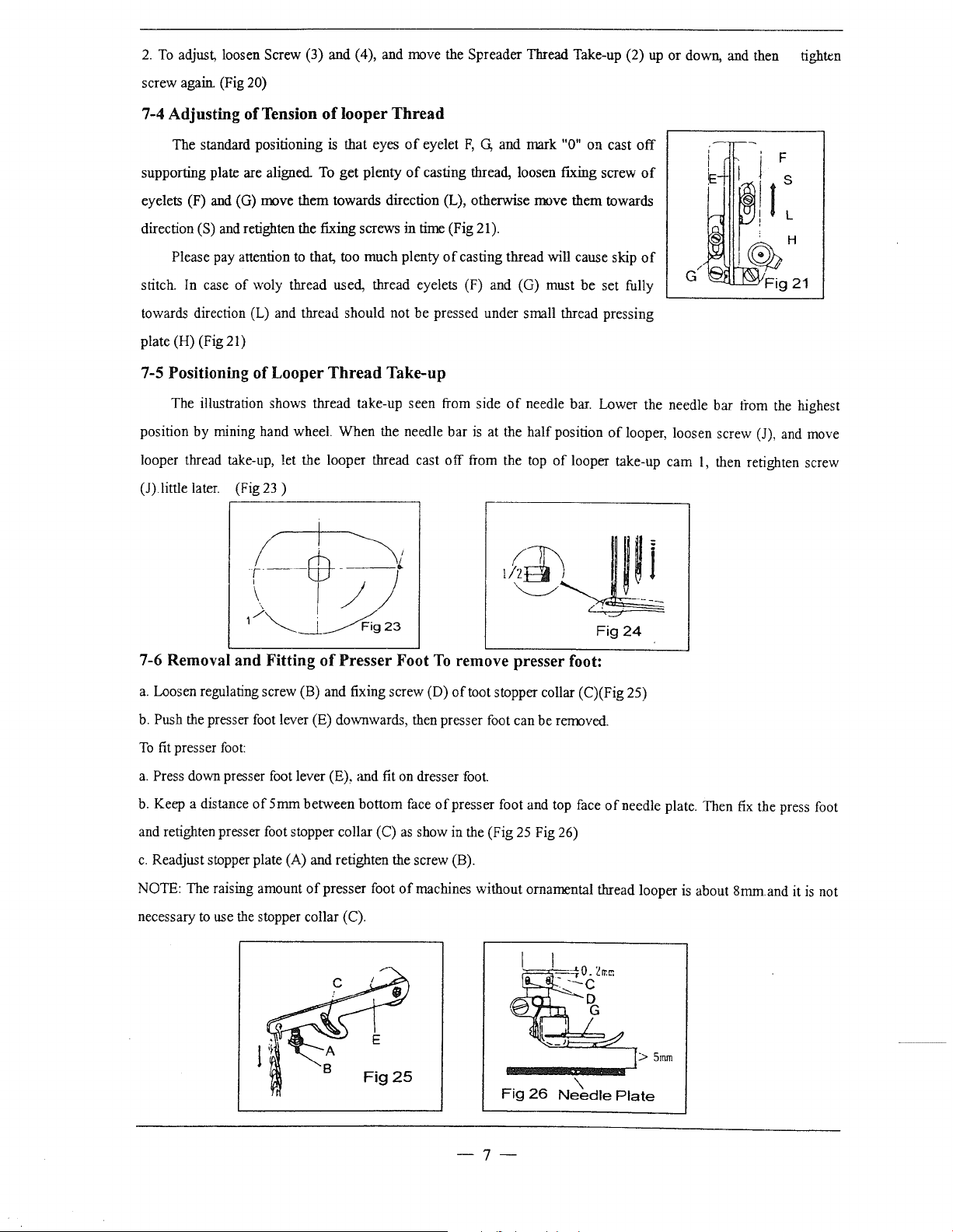
7-4 Adjusting of Tension
The standard positioning
supporting plate are aligned
eyelets (F) and (G) move them towards direction (L), otherwise move them towards
direction (S) and retighten the fixing screws in
Please pay attention to that, too much plenty
stitch. In case
towards direction (L) and
plate (H) (Fig 21)
of
woly thread used, thread eyelets (F) and (G) must be set fully
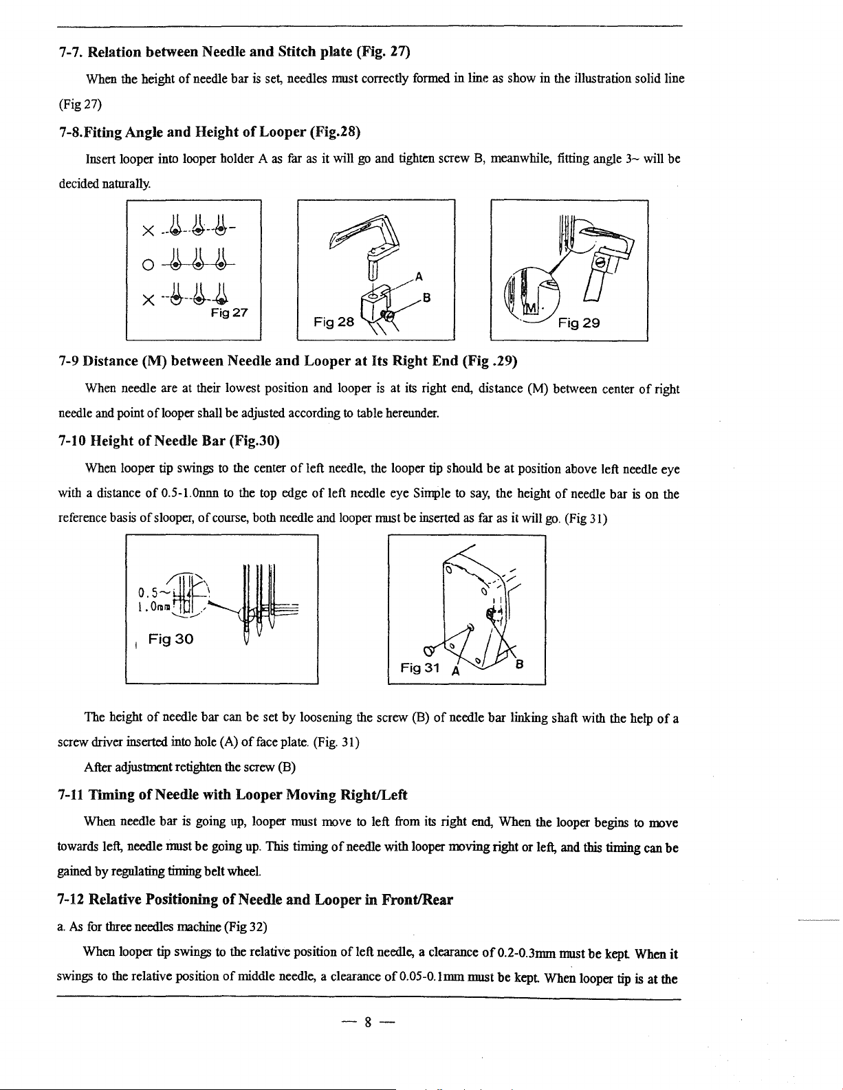
7-5 Positioning of Looper
The illustration shows thread take-up seen from side
position by mining hand wheel. When the needle
looper thread take-up, let the looper thread cast
(J).little later. (Fig
23)
of
looper
is
To
get plenty
thread should not be pressed under small thread pressing
Thread
that eyes
Take-up
Thread
of
eyelet
F,
G,
and mark "0" on cast
of
casting thread, loosen fixing screw
time
(Fig 21).
of
casting thread will cause skip
of
needle bar. Lower the needle bar from
bar
is
at the half position
off
from the top
of
off
of
of
of
looper, loosen screw (J), and move
looper take-up cam
.---------------------,
~
r--ffi-----L
the
1,
then retighten screw
highest
\ ( / )
1
/~__i_A23
7-6 Removal and Fitting
a.
Loosen regulating screw (B) and fixing screw (D)
b.
Push the presser
To
fit
presser
a.
Press down presser foot lever (E), and fit on dresser
b.
Keep a distance
and retighten presser foot stopper collar (C)
c.
Readjust stopper plate (A) and retighten the screw (B).
NOTE: The raising amount
necessary
to
foot
foot:
of5mm
use
the
stopper collar (C).
of
Presser Foot
lever (E) downwards, then presser
between bottom face
of
presser foot
To
ofpresser
as
show in the (Fig
of
machines without ornamental thread looper
Fig24
remove presser foot:
of
toot stopper collar (C)(Fig 25)
foot
can be removed.
foot.
foot and top face
25
Fig 26)
ofneedle
plate. Then
is
about 8mm.and it
fix
the press foot
is
not
Fig25
Fig
26
Needle
-7-
'\
>
Plate
5mm
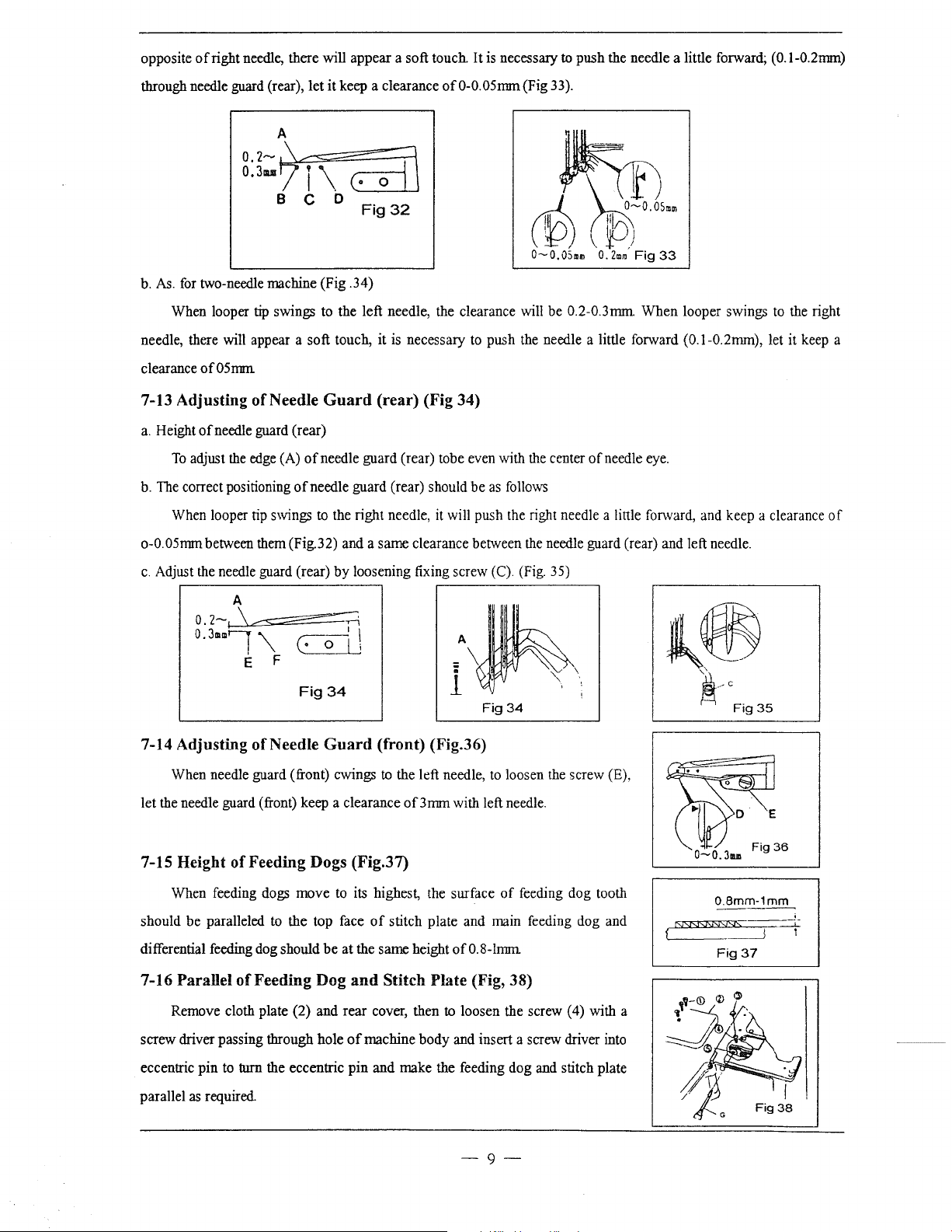
7-7. Relation between Needle
and
Stitch plate (Fig. 27)
When the height
(Fig 27)
7-S.Fiting Angle and Height
Insert looper into looper holder A
decided naturally.
of
needle
bar
is set, needles must correctly formed in line
of
Looper (Fig.28)
as
far
as
X
--~--~--~-
as
show in the illustration solid line
it
will go and tighten screw B, meanwhile, fitting angle 3-will
0~
X
--~--~-J.\
7-9 Distance (M) between Needle
When needle are at their lowest position and looper is at its right end, distance (M) between center
needle and point oflooper shall
7-10 Height ofNeedle
When looper tip swings to the center
Fig27
be
adjusted according
Bar
(Fig.30)
and
Looper
of
left needle, the looper tip should
at
Its Right
to
table hereunder.
End
(Fig .29)
be
at
position above left needle eye
of
be
right
of
with a distance
reference basis
The height
screw driver inserted into hole (A)
After adjustment retighten the screw (B)
7-11
Timing ofNeedle with Looper Moving Right/Left
When needle
towards left, needle must
gained
by
regulating
0.5-l.Onnn to the top edge
of
slooper,
o
s-·
1.0111111·1
1
Fig30
of
of
course, both needle and looper nrust
4.
'
_,......__.
1~
\
-.....:..::----
needle
bar
is going up, looper must move
be
timing
~
bar
can
be
of
going up.
belt wheel.
set
face plate. (Fig. 31)
This
of
left needle eye Simple to say, the height
-
by
loosening the screw (B)
timing
of
of
needle
be
inserted
to
left from its right end,
needle with looper moving right or left, and
of
as
needle
far as it will
bar
When
go.
(Fig 31)
linking shaft with the help
the looper begins to move
bar
this
timing can
is on the
of
be
a
7-12 Relative Positioning
a.
As
for three needles machine (Fig 32)
When
looper tip swings to the relative position
swings to the relative position
of
Needle
of
middle needle, a clearance
and
Looper
of
in
Front/Rear
left needle, a clearance
of0.05-0.lnnn
must
of
0.2-0.3nnn must
be
-8-
be
kept When it
kept When looper tip is
at
the
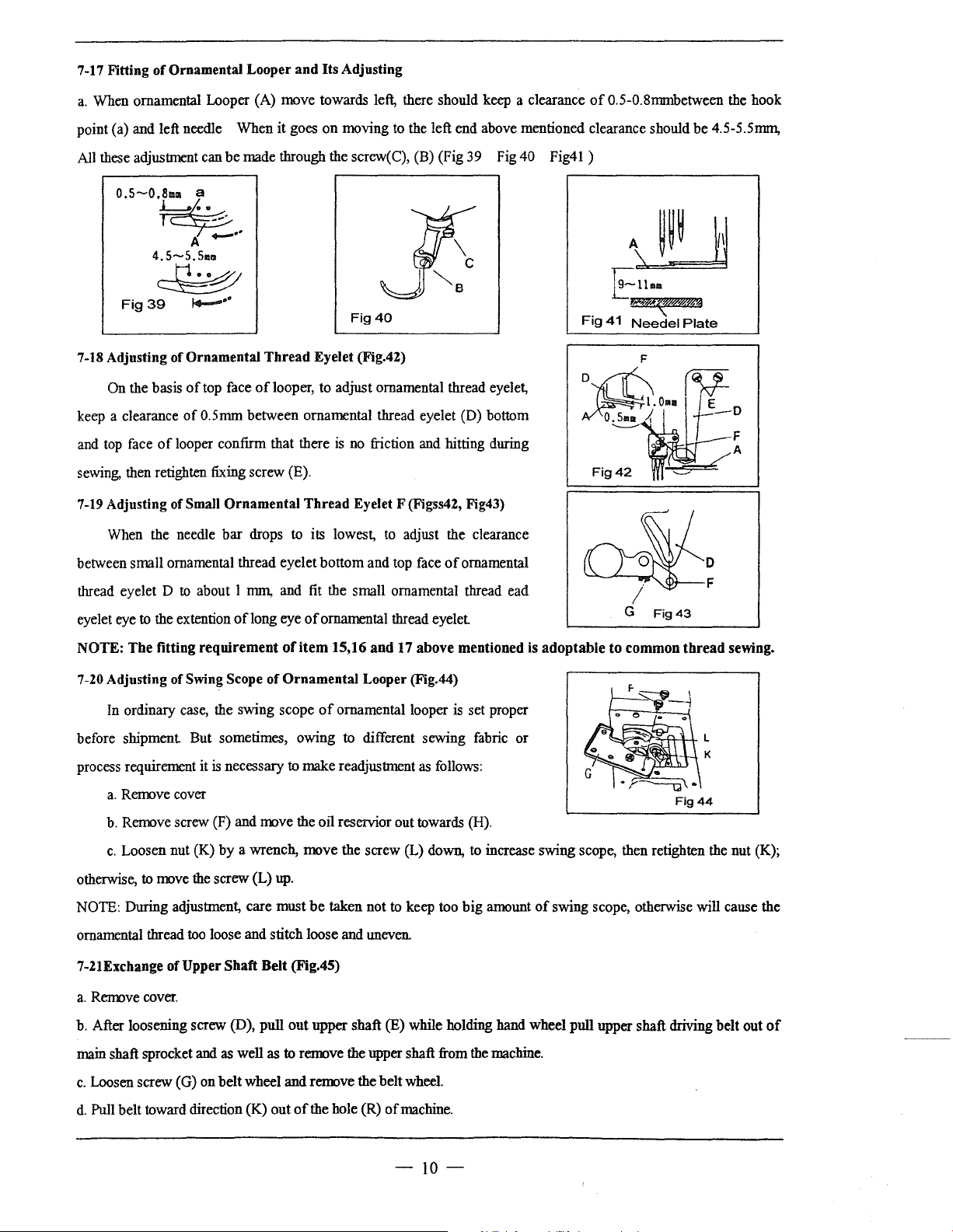
opposite
of
right needle, there will appear a soft touch.
It
is necessary to push the needle a little forward; (O.l-0.2nnn)
through needle guard (rear),
let
it keep a clearance
Fig32
of
0-0.05nnn (Fig 33).
~1)
\
\Lo.osu
~
) \
0-0.0Su
b.
As.
for two-needle machine (Fig .34)
When looper
needle, there will appear a soft touch, it is necessary to push the needle a little forward
clearance
of05mm
7-13 Adjusting of Needle
a.
Height
of
To
adjust the edge (A)
b. The correct positioning
When looper tip swings
tip
swings to the left needle, the clearance will
needle guard (rear)
of
of
needle guard (rear) should
be
Guard
needle guard (rear) tobe even with the center
to the right needle, it will push the right needle a little forward, and keep a clearance
(rear) (Fig 34)
be
as follows
!l-<J
0.2mro
0.2-0.3nnn.
of
needle eye.
Fig
When
33
looper swings to the right
(O.l-0.2rnm), let it keep a
of
o-0.05rmn between them (Fig.32) and a same clearance between the needle guard (rear) and left needle.
c.
Adjust the needle guard (rear)
7-14 Adjusting of Needle
When needle guard (front) cwings to the left needle, to loosen the screw (E),
let the needle guard (front) keep a clearance
7-15 Height
When feeding dogs
should
differential feeding dog should
7-16 Parallel
of
Feeding Dogs (Fig.37)
be
paralleled to the top face
of
Feeding Dog
by
loosening fixing screw (C). (Fig. 35)
Fig34
Guard
move
be
(front) (Fig.36)
of3nnn
to its highest, the surface
of
stitch plate and main feeding dog and
at the same height
and
Stitch Plate (Fig, 38)
- \
A~
: \
1 :
Fig34
with left needle.
of
feeding dog tooth
of0.8-lrrnn
k~
,,
~.-cFig35
0.8mm-1mm
NSNSJSN9%
L----__j
Fig37
;
--L
,
Remove cloth plate (2) and
screw driver passing through hole
eccentric
parallel as required.
pin
to turn the eccentric
rear
cover, then to loosen the screw (4) with a
of
machine
pin
body
and insert a screw driver into
and
make the feeding dog and stitch plate
-9-
7-17 Fitting of Ornamental Looper and Its Adjusting
a.
When ornamental Looper (A) move towards left, there should keep a clearance
of
0.5-0.Smmbetween the hook
point (a) and left needle When it goes on moving
All these adjustment can
o.s-0.~8mm
4.5-S.Sam
a
A
be
made through the screw(C), (B) (Fig 39 Fig 40
,
-··
~
Fig39
7-18 Adjusting of Ornamental Thread Eyelet (Fig.42)
On the basis
keep a clearance
top
and
sewing, then retighten
7-19
between small ornamental thread eyelet bottom and top face
face
Adjusting of Small Ornamental Thread Eyelet F (Figss42, Fig43)
When the needle bar drops
~+---··
of
top face oflooper, to adjust ornamental thread eyelet,
of
0.5mm between ornamental thread eyelet (D) bottom
of
looper confirm that there
fixing screw (E).
to
its lowest,
is
to
the left end above mentioned clearance should be 4.5-5.5mm,
11(
J"BC
Fig40
no
friction and hitting during
to
adjust the clearance
of
ornamental
Fig41)
Fig
A~
~llaa
!t!B~i%ik§
41
Needel
Plate
to
thread eyelet D
eyelet eye
NOTE:
7-20 Adjusting of Swing Scope of Ornamental Looper (Fig.44)
before shipment But sometimes, owing to different sewing fabric or
process requirement it
otherwise,
NOTE: During adjustment, care must
ornamental thread
7-21Exchange of Upper
a.
Remove cover.
b. After loosening screw (D), pull out upper shaft (E) while holding hand wheel pull
to
The
In
ordinary case, the swing scope
a.
Remove cover
b.
Remove screw (F) and move the oil reservior out towards (H).
c.
Loosen nut (K) by a wrench, move the screw (L) down,
to
about I nnn, and
the extention
fitting
move the screw (L)
oflong
requirement
is
necessary
too
loose and stitch loose and uneven.
Shaft Belt (Fig.45)
fit
the small ornamental thread ead
eye
of
ornamental thread eyelet
of
item
15,16
of
ornamental looper
to
make readjustment
up.
be
taken not
and
17 above mentioned
is
as
follows:
to
keep too big amount
is
adoptable to common
set proper
to
increase swing scope, then retighten the nut (K);
of
swing scope, otherwise will cause the
Fig44
upper
shaft driving belt out
thread
sewing.
of
main shaft sprocket
c.
Loosen screw (G) on belt wheel and remove the belt wheel.
d.
Pull belt toward direction (K) out
and
as
well as
to
remove the upper shaft from
of
the hole (R)
of
machine.
tb.e
machine.
-10-
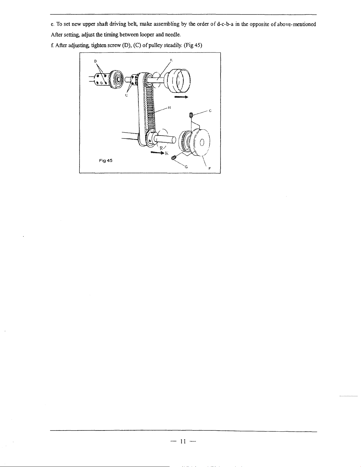
e.
To
set new upper shaft driving belt, make assembling
by
the order
of
d-e-b-a in the opposite
of
above-mentioned
After setting, adjust the
( After adjusting, tighten screw (D), (C)
D
timing
between looper and needle.
of
pulley steadily. (Fig 45)
-
11-
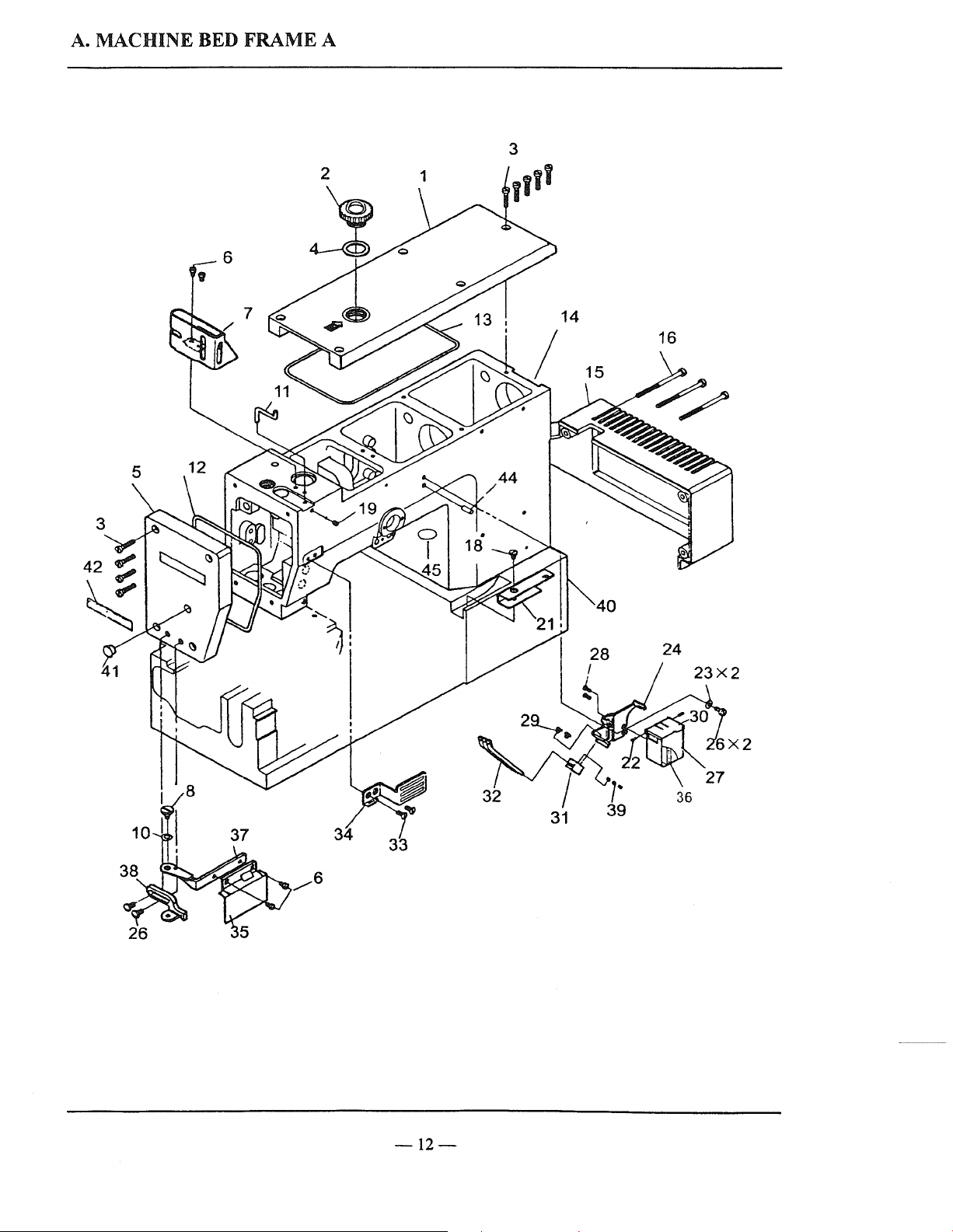
A.
MACHINE BED FRAME A
5
2 1
~
-12-
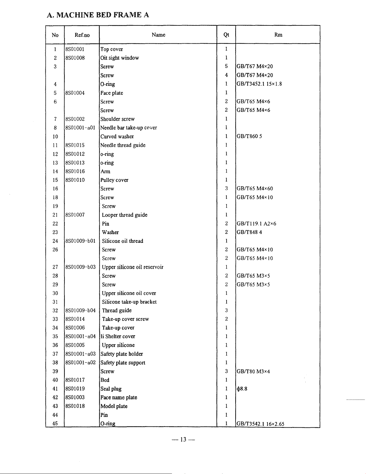
A.
MACHINE BED FRAME A
Ref
No
8S01001
1
8S01008 Oit sight window
2
3
4
8S01004
5
6 Screw
7 8S01002 Shoulder screw
8S01001-a01
8
10
8S01015
11
8S01012 o-ring
12
8S01013
13
8S01016
14
8S01010
15
16
18
19
8S01007
21
22
23
8S01009-b01
24
26
8S01009-b03
27
28
29
30
31
8S01009-b04
32
8S01014 Take-up cover screw 2
33
8S01006
34
8S01001-a04
35
36
8S01005 Upper silicone 1
8S01001-a03
37
8S01001-a02
38
39 Screw
40 8S01017
41
8S01019
8S01003
42
8S01018
43
44
45
no
Top cover
Screw
Screw
0-ring
Face plate
Screw
Needle bar take-up
Curved washer
Needle thread guide
o-ring
Ann
Pulley cover
Screw
Screw
Screw
Looper thread guide
Pin
Washer
Silicone oil thread
Screw
Screw
Upper
Screw
Screw
Upper
Silicone take-up bracket 1
Thread guide 3
Take-up cover
Ii Shelter cover
Safety plate holder
Safety plate support
Bed
Seal plug
Face name plate
Model plate
Pin
0-ring
silicone oil reservoir
silicone oil cover 1
Name
C<'ver
Qt
1
1
GBff67
5
4
GBff67
1 GBff3452.1
1
GBff65
2
2 GB/T65 M4x6
1
1
GBff860
1
1
1
1
1
1
3
GBff65 M4x60
1
GB/T65 M4x
1
1
2
GB/Tll9.1
2
GBff848
1
2 GB/T65
2 GB/T65 M4x I
1
2 GB/T65 M3x5
2 GB/T65 M3x5
1
1
1
1
3
GBff80
1
1
1}18.8
1
1
1
1
GB/T3542.1 16x2.65
M4x20
M4x20
M4x6
5
A2x6
4
M4x10
M3x4
Rm
I5xl.8
10
0
-13-
 Loading...