

Highlead GK3088-2 User Manual

HIGH
LEAD
GK3088-2
2-Needle,Feed-off-the-arm Double Chainstitcher Machine
Instruction Manual
Parts
SHANGHAI
HUIGONG
N0.3
Catalog
SEWING
MACHINE
FACTORY
HIGH
LEAD
GK3088-2
2-Needle,Feed-off-the-arm Double Chainstitcher Machine
Instruction Manual
Parts
SHANGHAI
HUIGONG
N0.3
Catalog
SEWING
MACHINE
FACTORY

-----CONTENTS-----
1. PRECAUTIONS BEFORE STARTING OPERATION-------------------------------------------------- 1
1) Safety precautions------------------------------------------------------------------------------------------ 1
2) Precaution before Starting
3) Precaution for Operating Conditions------------------------------------------------------------------- 1
2.
SPECIFICATIONS--------------------------------------------------------------------------------------------- 2
3.
SETTING
4.
LUBRICATION------------------------------------------------------------------------------------------------- 3
5.
ATTACHING A NEEDLE ------------------------------------------------------------------------------------- 3
6.
THREADING
7.
THREAD TENTION ------------------------------------------------------------------------------------------- 5
8.
ADJUSTING
9.
ADJUSTING
10. HEIGHT OF
11.
TIMING
UP
THE
THE
THE
THE
THE
TO
RELEASE
SEWING
MACHINE HEAD--------------------------------------------------------------------- 4
STITCH LENGTH--------------------------------------------------------------------- 5
LOOPER
FEED DOG------------------------------------------------------------------------------- 6
Oper~tion
------------------------------------------------------------------ 1
MACHINE------------------------------------------------------------------ 2
CAM ------------------------------------------------------------------------- 6
THE
NEEDLE THREAD TENTION----------------------------------------- 7
12.
ADJUSTING
13.
MOTOR PULLEY
PARTS
CATALOG --------------------------------------------------------------------------------------------------- 8
THE
INTERMEDIATE THREAD GUIDE----------------------------------------------- 7
AND
BELT------------------------------------------------------------------------------- 7
1.
PRECAUTIONS BEFORE STARTING OPERATION
1)
Safety precautions
(
1)
When turning the power on, keep your hands and fingers away from the area around/under the needle
and the area around the pulley.
Power must be turned off when the machine
(2)
off
(3) The power must be turned
adjusting the machine, or when replacing.
(4) Avoid placing fingers, hairs bars etc. nears the pulley,
is
the machine
Do
(5)
(6)
2)
Precaution before Starting Operation
(I)
(2)
(3) When a new sewing machine
(4) Verify the voltage and (single or three) phase with those given on the motor nameplate.
not insert fingers into the thread take-up cover, .under/round the needle, or pulley when the
machine
If
a belt cover, finger guard, and/or eye guard are installed, do not operate the machine without these
safety devices.
Never operate the machine unless it has been properly lubricated.
If
a drop oiler lubricates the machine, never operate the machine before lubricating.
power on.(the pulley should rotate counterclockwise when viewed from the pulley.)
operation. Injury could result.
is
in
operation.
before tilting the machine head, installing or removing the "V" belt,
is
first turned on, verify the rotational direction
is
not used,.
"V" belt, bobbin winder pulley, or motor when
of
the pulley with the
3) Precaution for Operating Conditions
(1) Avoid using the machine at abnormally high temperature
lower). otherwise, machine failure may result.
Avoid
(2)
(3) Avoid using the machine in areas where too much electrical noise, resulted from the high-frequency
(4) For the first month after the installation ofyour machine, run it at a lower speed (approx.
using the machine in dusty conditions.
is
welder and others,
generated.
(3s·c
or higher) or low temperature (5.Cor
3,300rpm)
-I-
2.
SPECIFICATIONS
Application
Number
Sewing speed
Needle
Height
Stitch length
Needle gauge 4.8,
Circumference
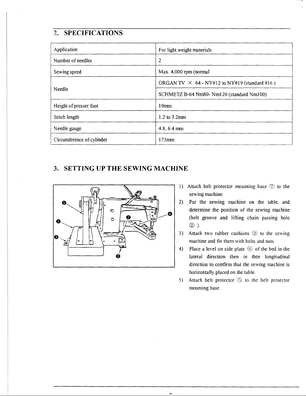
3. SETTING UP
of
needles 2
of
presser foot
of
cylinder 173mm
THE
SEWING MACHINE
For light weight materials
Max.
ORGAN TV X
SCHMETZ B-64
IOmm
1.2
4,000 rpm (normal
64-
NY#l2
Nm80-
to
3.2mm
6.4mm
I) Attach belt protector mounting base (j)
sewing machine.
Put the sewing machine on the table, and
2) .
determine the position
(belt groove and lifting chain passing hole
®
).
3) Attach two rubber cushions @
machine and
Place a level on side plate
4)
lateral direction then m
direction to confirm that the sewing machine
horizontally placed on the table.
5) Attach belt protector
mounting base.
to
NY#l9
Nml20
(standard NmlOO)
fix
them with bolts and nuts.
(standard
of
@
to
#16)
to
the
the sewing machine
to
the sewing
@)
of
the bed
thee longitudinal
the belt protector
in
the
is
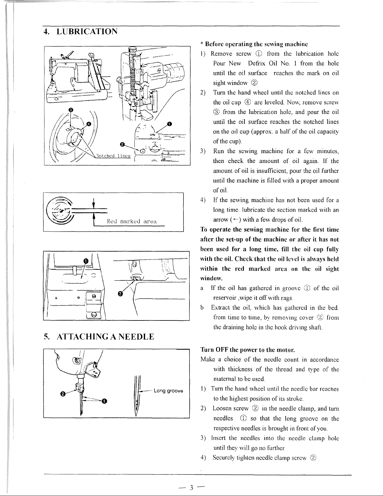
4.
LUBRICATION
5.
ATTACHING A
t
!(cJ
rnarkuJ
area
1-/
NEEDLE
*
Before
I) Remove screw
2) Tum the hand wheel until the notched lines on
3) Run the sewing machine for a few minutes,
4)
To
after
been used
with
within
window.
a
b Extract the oil, which has gathered in the bed.
operating
Pour New Defrix Oil
until the oil surface reaches the mark on oil
sight window
the oil cup
@ from the lubrication hole, and pour the oil
until the oil surface reaches the notched lines
on the oil cup (approx. a
of
the cup).
then check the amount
amount
until the machine
of
If
long time. lubricate the section marked with an
arrow (
operate
the
the
If
reservoir ,wipe it
from time to time, by removing cover
the draining hole
of
oil.
the sewing machine has not been used for a
.._) with a few drops
the
set-up
for
oil.
Check
the
red
the oil has gathered in groove
the
sewing
CD
@
@ are leveled. Now, remove screw
oil
is
insuftlcient, pour the oil further
is
sewing
of
a long
machine
the
machine
time,
that
marked
off
in
the hook driving shaft.
machine
from the lubrication hole
No.
1 from the hole
half
of
the oil capacity
of
oil again.
filled with a proper amount
of
oil.
for
the
or
after
till
the
oil cup full)'
the
oil level
area
on
is
the
CD
with rags.
If
tirst
time
it has not
always held
oil sight
of
the oil
(?:)
from
the
Turn
OFF
Make a choice
vvith
maternal
~-
Loog
gmo"
--
I) Tum the hand wheel until the needle bar
to
the highest position
2) Loosen screw
needles
respective needles
3) Insert the needles into the needle clamp hole
until they
4) Securely tighten needle clamp scre\v
3-
the
power
of
thickness
to
be used.
CD
\vill go
to
the
motor.
the needle count in accordance
of
the thread and type
of
its stroke.
of
the
reaches
@ in the needle clamp, and tum
so that the long groove on the
is
no
brought
further
in
front
of
@
you.
6.
THREADING THE MACHINE HEAD
Rignt-hand
"""'
'"'j"
Left-hand
needle thread
Rtght·hand
needle
thread
~~
~~
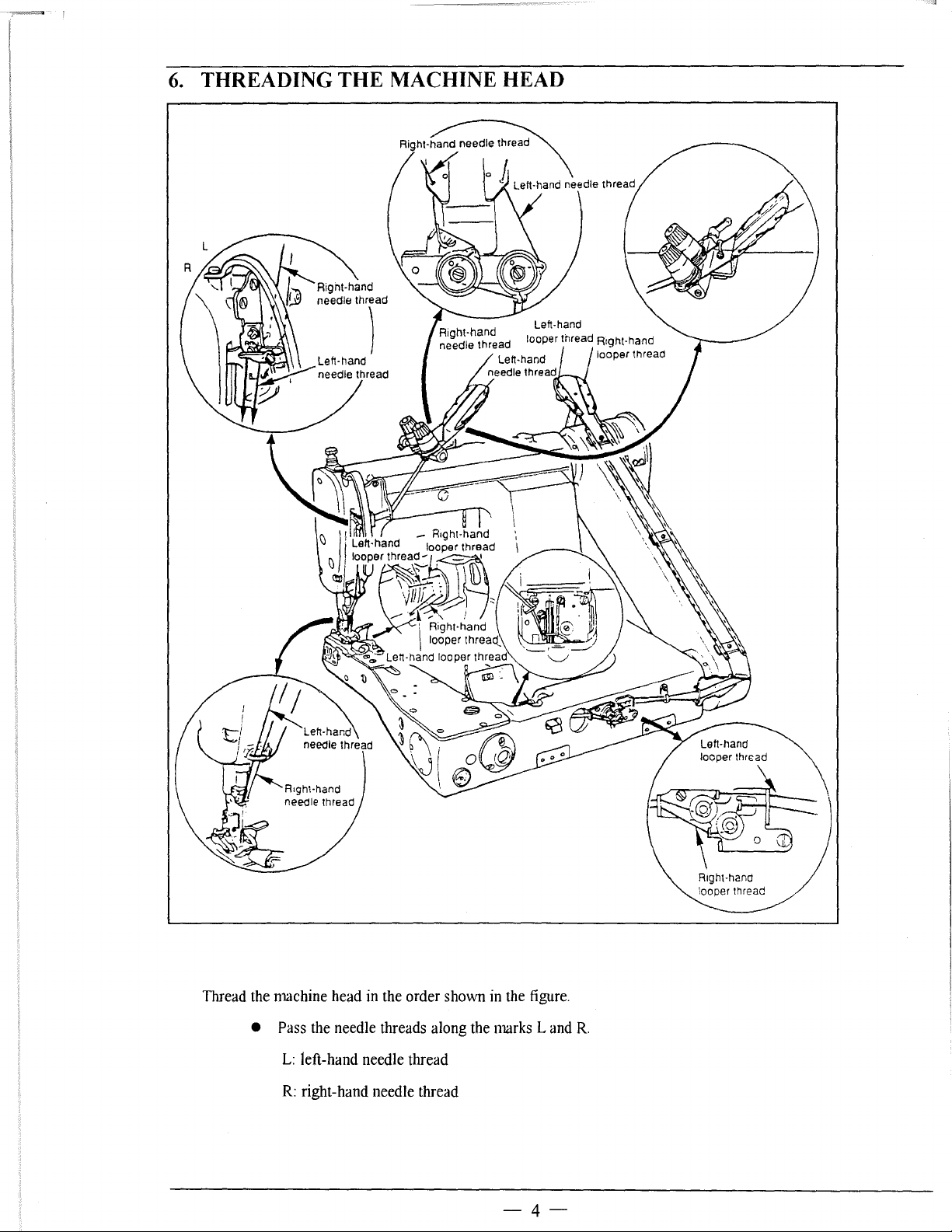
Thread the machine head in the order shown in the figure.
• Pass the needle threads along the marks L and
L:
left-hand needle thread
R:
right-hand needle thread
-4-
R.
7.
THREAD TENTION
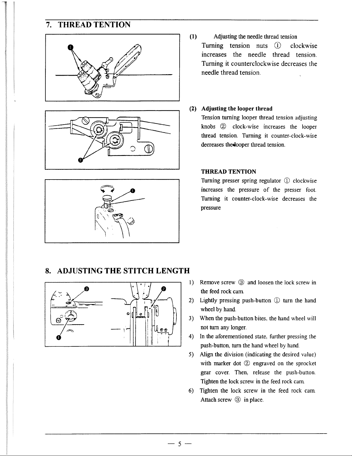
(1) Adjusting the needle thread tension
Turning tension nuts
increases the needle thread tension.
Turning it counterclockwise decreases the
needle thread tension.
(2) Adjusting the looper thread
Tension turning looper thread tension adjusting
knobs
thread tension. Turning it counter-clock-wise
decreases
THREAD TENTION
Turning presser spring regulator
increases the pressure
Turning
pressure
® clock-wise increases the looper
thetlooper thread tension.
it
counter-clock-wise decreases the
CD
clockwise
CD
clockwise
of
the presser foot.
8.
ADJUSTING THE STITCH LENGTH
-~~
1) Remove screw ® and loosen the lock screw in
by
cam
hand.
CD
turn the hand
® engraved on the sprocket
cam
cam
the feed rock
2) Lightly pressing push-button
wheel
3) When the push-button bites, the hand wheel will
turn any longer.
not
4) In the aforementioned state, further pressing the
push-button, tum the hand wheel by hand.
5) Align the division (indicating the desired value)
with marker dot
gear cover. Then, release the push-button.
Tighten the lock screw in the feed rock
6) Tighten the lock screw in the feed rock
Attach screw ® in place.
-5-
I 0
®
Lock
screw~
CID
9.
ADJUSTING
10.
HEIGHT
11
(Jj)
~
~
~I
@,
0
THE
OF
THE FEED DOG
LOOPER
CAM
Caution
the
Never press
machine
sewing
Never
Loosen screw
that
returning
projected
I) Adjusting the thread guide
is
machine
operate
it draws
to its home position
the
cam. Adjust the top end
the marker line. The standard position
thread guide is obtained by adjusting the top
end
of
located this side.
screw
(:;£)
guide to the center marker line.
is
not necessary to re-adjust the looper thread
cam timing.
push-button
in operation. Be sure to operate the
after
tightening
the
machine with screw 0 removed.
®,
and
adjust
the
thread
most.
the thread guide to the marker line
If
cotton thread
and adjust the top end
while the sewing
the
looper cam
when
the
looper starts
after
of
the looper
of
the
tl1read
is
of
At
lock screw.
used. loosen
this time,
CD
so
it has
tlu·ead
guide to
of
the
the thread
it
0.
1-lmm
~r
Throat plate
_;_l;T<-;;-...-_-=--E'=-
"
~~
(~Higher
~Lower
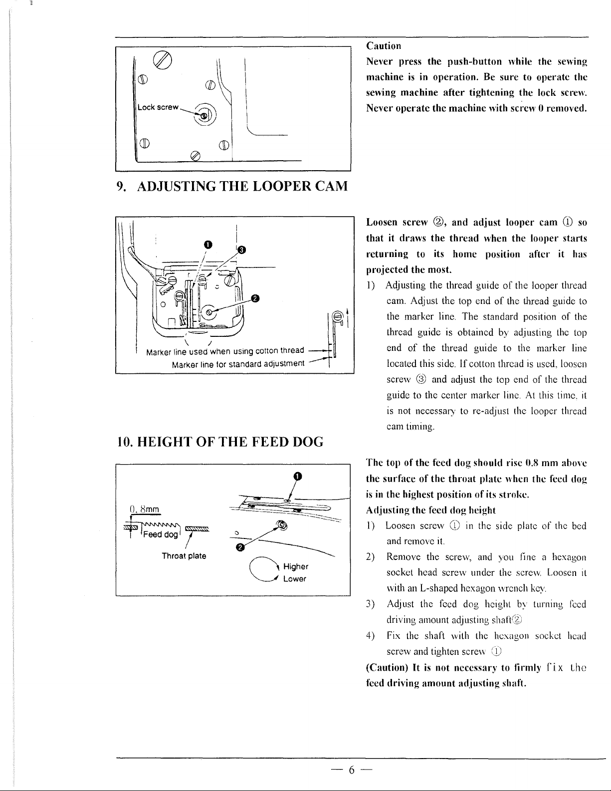
The
top of
the
feed dog should rise 0.8 mm
the
surface
is
in
the highest position
Adjusting
1)
Loosen screw
and remove
2) Remove the screw, and you fine a hexagon
socket head screw under the screw. Loosen
vvith
3) Adjust the feed dog height by turning
driving amount adjusting shaft@
4) Fix the shaft with the hexagon socket head
screw and tighten screw
(Caution)
feed driving
of
the
throat
the
feed dog height
CD
it.
an
L-shapcd hexagon wrench
plate
of
its stroke.
in
the side plate
CD
It
is
not necessary to tirmly
amount
adjusting shaft.
when the feed dog
key.
of
the bed
f'
i x Lhc
abow
feed
it
-6-
 Loading...