

Page 1
Purchasing
Copy
Dept
HIGH
HIGH
GK22018
SPEED CYLINDRICAL BED
CHAIN
Instruction
LEAD
SERIES
STITCHER
Manual
INTERLOCK
Parts
SHANGHAI
HUIGONG
N0.3
Catalog
SEWING
MACHINE
FACTORY
Page 2

Page 3
CONTENTS
1 ,
In
traduction----------------------------------------------------------------------------------------------------------------- 1
, Mode and Specification --------------------------------------------------------------------------------------------------- 1
2
,
Ins
ta
3
4,
, Lubrication -----------------------------------------------------------------------------------------------------------------2
5
5-1
5-2 Feeding
5-3
5-4
5-5
6
, Proper Operation----------------------------------------------------------------------------------------------------------- 3
6-1
6-2
6-3
6-4 Thread
6-5
6-6 Adjusting
6-7 Adjusting
7,
7 -I Tension
7-2
7-3
7-4 Adjusting
7-5
7-6 Remove and Fitting
7-7 Relation
7-8
7-9
7-10 Adjusting
7
7-12 Relative Postioning ofNeedle and Looper
7-1
7-14 Adjusting o
7-15 Height
7-16 Paralleling
7-17 Fitting
7-18 Fitting
7-19 Fitting
7-20 Adjusting
7-21
8 , Parts book -----------------------------------------------------------------------------------------------------------------
lla tion ------------------------------------------------------------------------------------------------------------------ 1
Sewing Speed and Setting up
Oil
to
be Used------------------------------------------------------------------------------------------------------------- 2
of
Oil-------------------------------------------------------------------------------------------------------------2
Oil Sight Gauge and Check Procedure
Ex
change
Cleaning
Needles
Threading ------------------------------------------------------------------------------------------------------------------4
Operation
Pressure
Proper Adjusting
Adjusting ofNeedle Thread Upper Eyelet----------------------------------------------------------------------------- 6
Adjusting
Positioning
Fitting Angle and Height
Distance (M) Between Needle and Looper ----------------------------------------------------------------------------8
-II
Timing
3 Adjusting o
Exchange
of
Oil-----------------------------------------------------------------------------------------------------------3
of
Filter and Screen--------------------------------------------------------------------------------------------4
to
Be Used, Fitting
of
Spring-out Type Bobbin Thread Guide -----------------------------------------------------------------4
Tens
ion ------------------------------------------------------------------------------------------------------------4
of
Presser Foot and Its Adjustment--------------------------------------------------------------------------- 5
of
Stitch Length -----------------------------------------------------------------------------------------------5
of
Differential Feeding--------------------------------------------------------------------------------------- 6
of
Machine--------------------------------------------------------------------------------------------- 6
ofN
eedle Thread------------------------------------------------------------------------------------------------ 6
of
Ornamental Thread---------------------------------------------------------------------------------------- 6
of
Looper Thread --------------------------------------------------------------------------------------------- 7
of
Looper Thread Take-up Cam--------------------------------------------------------------------------- 7
of
ofN
eedle and stitch plate ------------------------------------------------------------------------------------- 8
ofN
eedle Bar------------------------------------------------------------------------------------------------ 8
ofN
eedle With Looper Moving Right/Left------------------------------------------------------------------ 8
fN
eedle Guard( Rear) ------------------------------------------------------------------------------------ 9
fN
eedle Guard(Front) ----------------------------------------------------------------------------------- 9
of
Feed Dog----------------------------------------------------------------------------------------------------- 9
ofF
eed Dog With Stitch Plate---------------------------------------------------------------------------- 9
of
Ornamental Looper and Its Adjusting-------------------------------------------------------------------
of
Ornamental Thread Guide--------------------------------------------------------------------------------
of
Ornamental Thread Eyelet ------------------------------------------------------------------------------
of
Swing Scope
of
Upper Shaft Driving Belt -----------------------------------------------------------------------------
of
Pulley --------------------------------------------------------------------------------- 2
of
Oil Cycling-------------------------------------------------------------- 3
ofN
eedles; Needle Thread and Needle Device--------------------------------------- 3
Presser Foot and
of
Looper ------------------------------------------------------------------------------------ 8
of
Ornamental Looper-----------------------------------------------------------------
Its
Height------------------------------------------------------------------- 7
in
Front/Rear----------------------------------------------------------- 8
10
10
10
10
10
12
Page 4

Page 5

1.
Introduction
Model GK31 058 Interlock stitch sewing machine
clothing, and underwear, etc. This series
stitch, loop type interlock stitch, fell interlock stitch, collar and band binding stitch, ornamental stitch which are even,
attractive, decorative, elastic and can
of
trousers waist, underclothes, underpants, front
be used
2.
as
different industrial sewing machines
Specifications
Dimensions:
Weight (Head):
Sewing Speed: Max. 6000 r.p.m Feed length: 1.2-4mm
Needle: Model UY128 GAS NM65-90, 128GAS 9-14
Needle Bar Stroke:31.2mm
Adjusting Form
Differential Ratio: Positive Ratio 1:1.3 Reverse 1 :0.5
Lubrication: With Oil Pump Automatic Oil Supply Lubricant: No.7 White Machine Oil
Oil Reserving Capacity: 1
Motor: Clutch motor: >400W,3phase,2pde.
585(L)X370
51
kg Type
of
Differential Feeding: Lever Type (It can also
(W)
OOOg
of
products is capable
be
met demands
of
to
sew zip, embroider and abut decorative lace and scallop lace etc.
X510
of
Presser Foot Raising
(H)
Stitch: 406,407,602,605( 401.408)
is
a Special equipment suitable for trades
of
sewing many stitches, fox example, plain interlock
of
sewing elastic trousers
garment etc. With proper attaching device and parts, it can also
Height:>
5mm
be
regulated
of
man and woman and elastic Cord
at
any time during operation)
of
kintwear,
3. Installation
Referring
l\...
to
the illustration install the machine correctly.
~
15
~
-
c;::::
B-B
SECTION
Unit::mm
Difference: ± 2
1.{')
'<t
'<t
.-
Ol
.-
V l n I
4-¢13
Ol
.-
.-
I
i
234
5-R1d~
I I
'\'
-=<~-l.....t~S
1200
·-·-4~
125
234
710
461
I___)
i B
I
.
90
400
302
245
'<t
<0
N N
210
-}-
Page 6
4. Sewing Speed
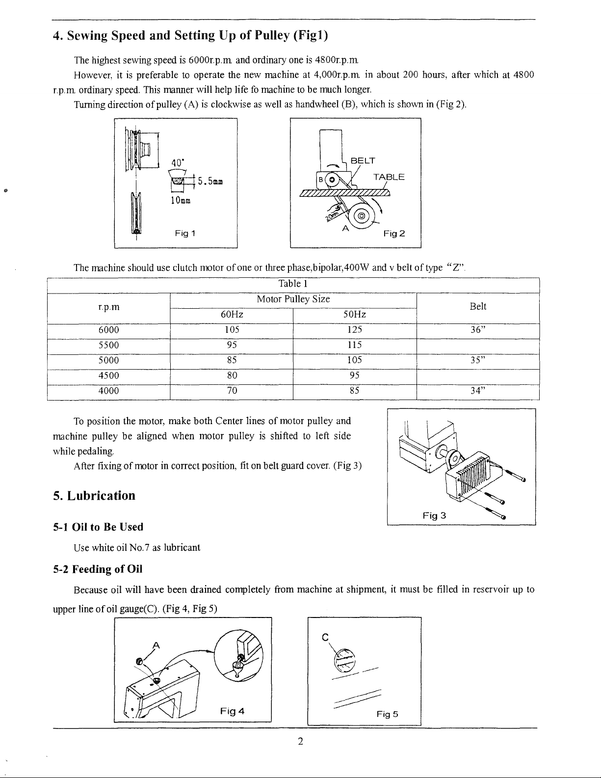
The highest sewing speed is 6000r.p.m and ordinary one is 4800r.p.m
However, it
r.p.m ordinary speed. This manner will help life
Turning direction
and
Setting Up
is
preferable to operate the new machine at 4,000r.p.m in about 200 hours, after which at 4800
of
pulley (A)
is
of
clockwise
Pulley
fo
machine
as
well
(Figl)
to
be
as
handwheel (B), which
much longer.
is
shown in (Fig 2).
..
fJ
40"
~5.5m.m
lOmm
~
The machine should use clutch motor
r.p.m
6000
5500
5000
4500
4000
To
position the motor, make
machine pulley
while pedaling.
After fixing
be
aligned when motor pulley
of
motor in correct position, fit on belt guard cover. (Fig 3)
Fig
1
both
of
one or three phase,bipolar,400W and v belt
Table 1
Motor Pulley Size
60Hz 50Hz
105
95
85
80
70
Center lines
of
motor pulley and
is
shifted
to
left side
125
115
105
95
85
of
type
"Z".
Belt
36"
35"
34"
5.
Lubrication
5-1
Oil to Be Used
Use white oil No.7 as lubricant
5-2 Feeding
Because oil will have been drained completely from machine at shipment, it must
upper line
of
Oil
of
oil gauge( C). (Fig
4,
Fig 5)
~
2
Fig
Fig
3
be
filled in reservoir
5
up
to
Page 7
5-3 Oil Sight
Gauge
and
Check
Procedure
of
Oil
Cycling.
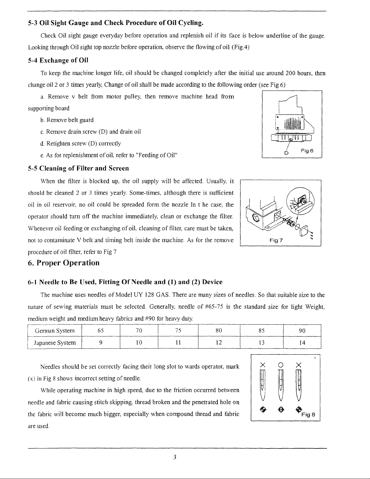
Check Oil sight gauge everyday before operation and replenish oil
Looking through Oil sight top nozzle before operation, observe the flowing
5-4 Exchange
To
keep the machine longer life, oil should
change oil 2 or 3 times yearly, Change
a.
Remove v belt from motor pulley, then remove machine head
supporting board
b.
Remove belt guard
c.
Remove drain screw (D) and drain oil
d.
Retighten screw (D) correctly
e.
As
5-5 Cleaning
When the filter
should be cleaned 2 or 3 times yearly Some-times, although there
oil
in
oil
of
Oil
for replenishment
of
Filter
is
blocked
reservoir,
no
oil could
of
and
be
changed completely after
of
oil, refer
oil shall
to
be
"Feeding
made according
of
Oil"
Screen
up,
the oil supply will
be
spreaded form the nozzle In t he case, the
be
affected. Usually,
to
the following order (see Fig
is
sufficient
if
its face
of
oil (Fig.4)
the
from
is
below underline
initial use around 200 hours, then
.--------------.
it
6)
of
the gauge.
operator should turn
Whenever oil feeding or exchanging
not
to
contanrinate V belt and rinring belt inside the machine.
procedure
6.
6-1
nCJture
medium weight
Genmm System
JCJpanese
(x)
needle and fabric causing stitch skipping, thread broken and the penetrated hole
of
oil filter, refer
Proper
Operation
Needle to Be Used,
The machine uses needles
of
sewing
System 9
Needles should
in
Fig 8 shows incorrect setting
While operating machine in high speed, due to the friction occurred between
off
the machine immediately, clean or exchange the filter.
of
oil, cleaning
to
Fig 7
Fitting
materiCJls
CJnd
medium heavy fabrics and #90 for heavy duty
be
must
65
set correctly facing their long slot
Of
Needle
of
Model UY 128 GAS. There are many sizes
be
selected. Generally, needle
70
10
of
needle.
of
and
(1)
filter, care must be taken,
As
for the remove
and
(2) Device
of
#65-75
75
11
to
wards operator, mark
is
80
12
Fig 7
of
needles.
the standard size for light Weight,
So
that suitable size
85
13
90
14
X 0 X
on
~ ~
~
...
to
the
the fabric will become much bigger, especially when compound thread and fabric
are used.
3
~Fig
8
Page 8
To
prevent from occurring above case, the machine
(l)
standardized
cooling (Fig.9)
To
achieve most efficient effect
Generally, we suggest
the,covers
If
these devices are not necessary,
tips
and thread
device-for needle thread lubrication and (2) device-for needle
of
them, check the oil amount and make feeding
to
touch them
6-2 Threading
to
use these devices
is
equipped
of
these devices, silicon oil should be used.
as
much
as
possible and often open
of
silicon oil in time.
it's
better for you
to
take out felt from
~ ~
~w
CD
Fig
(l),
(2) devices and not let the needle
0
9
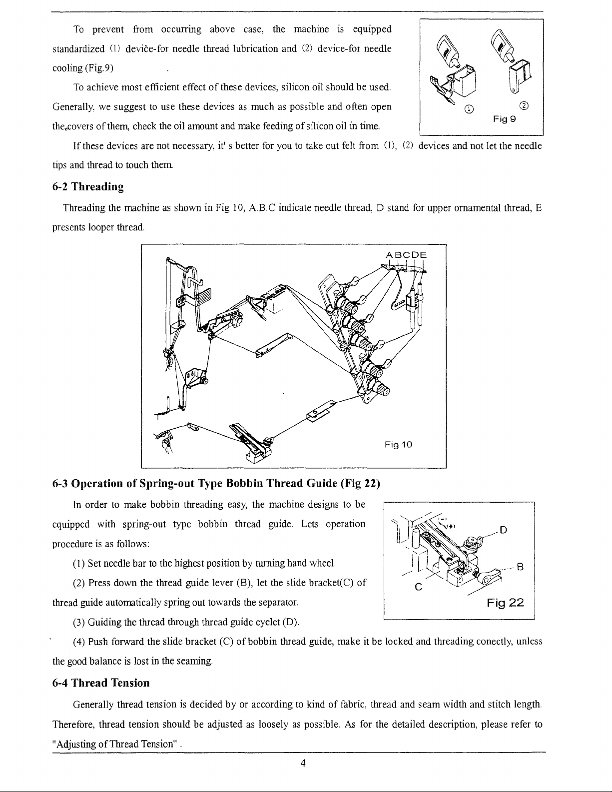
Threading the machine
presents looper thread.
6-3 Operation
of
as
shown in Fig
10,
A
B.
C indicate needle thread, D stand for upper ornamental thread, E
Spring-out Type Bobbin Thread Guide (Fig 22)
ABC
Fig
DE
10
In
order
to
make bobbin threading easy, the machine designs
equipped with spring-out type bobbin thread guide. Lets operation
procedure
thread guide automatically spring out towards the separator.
the good balance
is
as
follows:
1)
Set needle bar
(
Press down the thread guide lever (B), let the slide bracket(C)
(2)
(3) Guiding the thread through thread guide eyelet (D).
(
4)
Push forward the slide bracket (C)
to
the highest position by turning hand wheel.
is
lost in the seaming.
of
bobbin thread guide, make it be locked and threading conectly, unless
to
be
of
6-4 Thread Tension
Generally thread tension is decided
Therefore, thread tension should be adjusted
"Adjusting
of
Thread Tension".
by
or according
as
loosely
to
kind
as
possible.
4
of
fabric, thread and seam width and stitch length.
As
for the detailed description, please refer
Fig22
to
Page 9
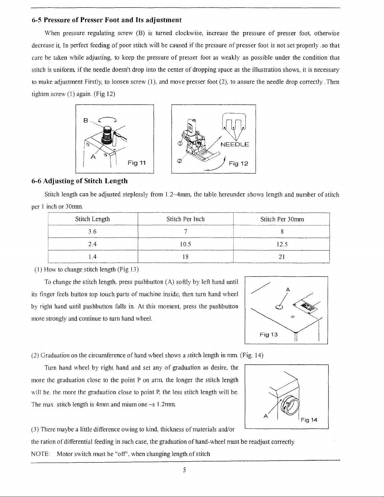
6-5 Pressure
of
Presser Foot and Its adjustment
When pressure regulating screw (B)
it,
decrease
care be taken while adjusting,
stitch
to
make adjustment Firstly, to loosen screw
tighten screw (1) again. (Fig 12)
6-6 Adjusting
per 1 inch or
In perfect feeding
is
uniform,
Stitch length can
if
the needle doesn't drop into the center
of
Stitch Length
30nnn
be
of
poor
to
keep the pressure
Fig
adjusted steplessly from
is
turned clockwise, increase the pressure
stitch will
(1
), and move presser foot (2), to
11
be
caused
1.2~4mm,
if
the pressure
of
presser foot as weakly
of
dropping space as
the table hereunder shows length and number
of
of
presser
assure
foot is not set properly .so that
as
possible under the condition that
the
illustration shows, it
the needle drop correctly . Then
[~
NEEDLE
presser foot, otherwise
is
necessary
of
stitch
Stitch Length
~
(I)
How
to
change stitch length (Fig 13)
To
change the stitch length, press pushbutton (A) softly
its finger feels button top touch parts
by right hand until pushbutton falls
more strongly and continue
(2) Graduation
Tum hand wheel
more the graduation close
will be. the more the graduation close
3.6
2.4
1.4
to
on
the circumference
by
right hand and set any
to
tum hand wheel.
ofhand
the point P on arm, the longer the stitch length
Stitch
Per Inch
7
10.5
18
by
left hand until
of
machine inside, then turn hand wheel
in.
At this moment, press the pushbutton
wheel shows a stitch length in
of
to
point
graduation
P,
the less stitch length will be.
as
desire, the
mm
Stitch
/ A
Fig
(Fig. 14)
Per 30mm
8
12.5
21
j
13
is
4mm
The max. stitch length
(3) There maybe a little difference owing
the ration
NOTE: Motor switch must
of
differential feeding in such case, the graduation ofhand-wheel must
and mium one
be
"off', when changing length
~s
1.2mm
to
kind, thickness
of
materials and/or
of
stitch
5
A
be
readjust correctly.
Page 10
6-7 Adjusting
of
the
Differential Feed Ratio
The differential Feed Ratio
1:1.3(Fig. 15)
To
adjust the ratio, loosen the nut (2), move the indicator (1)
To
stretch the cloth, move the indicator (1) upward;
To
gather the cloth, move the indicator (1) upward.
7.
Proper
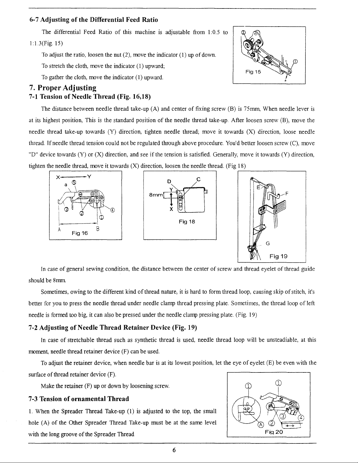
7-1
Tension
The distance between needle thread take-up (A) and center
at its highest position, This is the standard position
needle thread take-up towards (Y) direction, tighten needle thread; move it towards (X) direction, loose needle
thread.
"D" device towards (Y) or (X) direction, and see
tighten the needle thread, move it towards (X) direction, loosen the needle thread. (Fig 18)
Adjusting
of
Needle
If
needle thread tension could not be regulated through above procedure. You'd better loosen screw (C), move
Thread
of
this machine is adjustable from 1:0.5 to
up
of
down.
(Fig. 16,18)
of
fixing screw (B) is 75mrn, When needle lever
of
the needle thread take-up. After loosen screw (B), move the
if
the tension is satisfied. Generally, move
it
towards (Y) direction,
is
.------------------,
X y
a
6:
D
c
~®
i
1 °
' '
A
Fig
In
case
of
general sewing condition, the distance between the center
should be 8nnn
Sometimes, owing to the different kind
better
for
you
to
press the needle thread under needle clamp thread pressing plate. Sometimes, the thread loop
needle
is
formed
7-2 Adjusting
In case
moment, needle thread retainer device (F) can
To
adjust the retainer device, when needle
surface
of
too
of
of
stretchable thread such
thread retainer device (F).
__
!
1m
8
16
big, it can also
Needle
Thread
be
pressed under the needle clamp pressing plate. (Fig. 19)
Retainer
as
X
Fig
of
thread nature, it is hard
Device (Fig. 19)
synthetic thread
be
used.
bar
is
is
at its lowest position, let the eye
18
of
screw and thread eyelet
to
form thread loop, causing skip
used, needle thread loop will
of
eyelet (E)
G
Fig
19
of
thread guide
of
stitch, it's
be
unsteadiable, at this
be
even with the
of
left
Make the retainer (F) up or down by loosening screw.
7-3 Tension
1.
When the Spreader Thread Take-up (1)
hole (A)
with the long groove
of
ornamental
of
the Other Spreader Thread Take-up must
of
the Spreader Thread
Thread
is
adjusted
to
the top, the small
be
at the same level
6
Page 11
2.
To
adjust, loosen Screw (3) and ( 4), and move the Spreader Thread Take-up (2) up or down, and then tighten
screw again. (Fig
7-4 Adjusting
The standard positioning is that eyes
supporting plate are aligned.
eyelets (F) and (G) move them towards direction (L), otherwise move them towards
direction (S) and retighten the fixing screws in time (Fig 21).
Please pay attention to that, too much plenty
stitch. In case
towards direction (L) and thread should not
plate (H) (Fig 21)
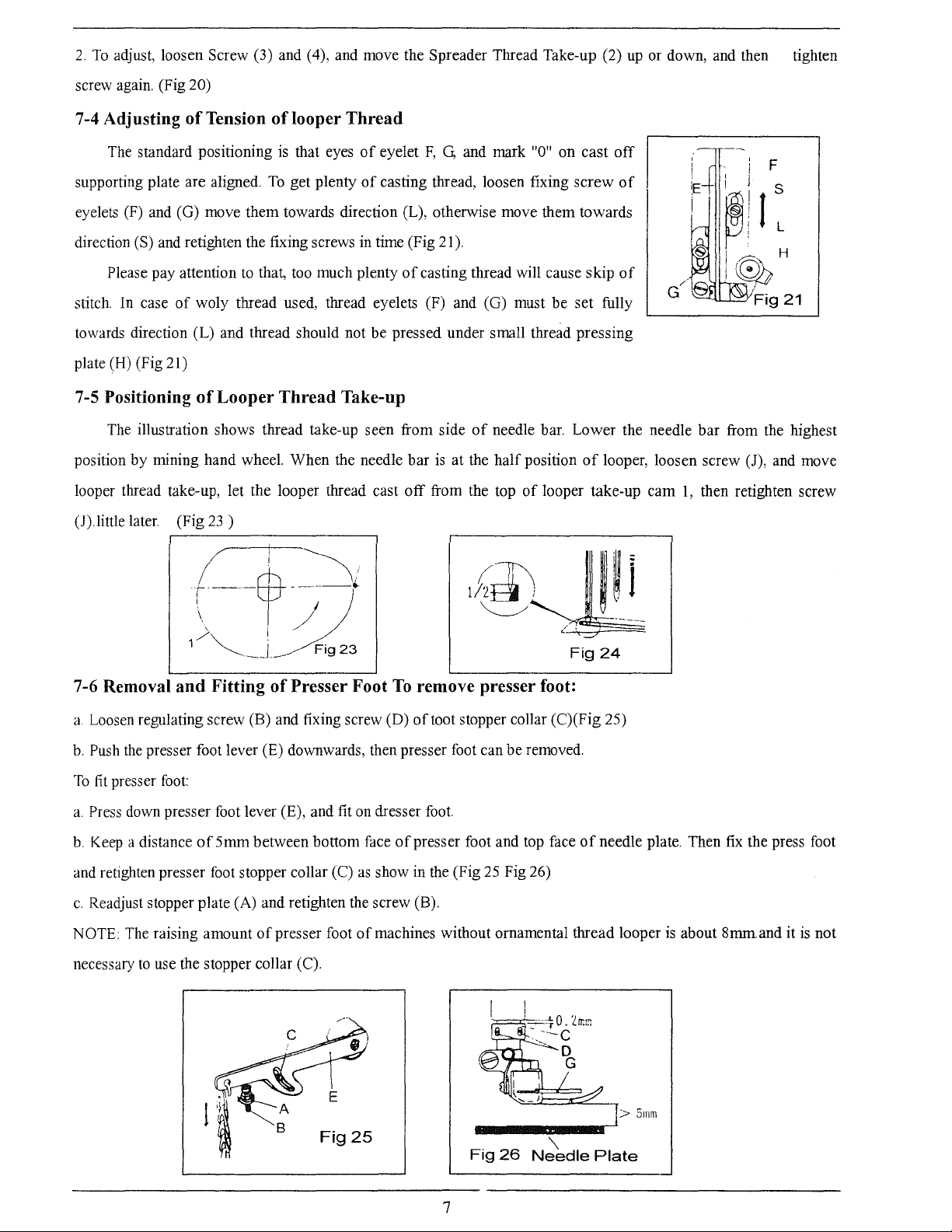
7-5 Positioning
The illustration shows thread take-up seen from side
position
looper thread take-up, let the looper thread cast
(J).little later. (Fig
by
20)
of
Tension
of
woly thread used, thread eyelets (F) and (G) must
of
Looper
mining hand wheel. When the needle
23
of
looper
To
get plenty
Thread
)
Thread
of
eyelet
F,
G,
of
casting thread, loosen fixing
of
casting thread will cause skip
be
pressed under small thread pressing
Take-up
bar
is
at the
off
from the top
and mark "0" on
of
needle bar. Lower the needle
half
position
of
cast
off
screw
be
set fully
of
looper, loosen screw (J), and move
looper take-up
of
of
cam
F
bar
from the highest
1,
then retighten screw
( i
r----ffi--
\ i /
\
1
/~
7-6 Removal
a.
Loosen regulating screw (B) and fixing screw (D)
b.
Push
the
To
fit
presser
a.
Press down presser foot lever (E), and fit on dresser foot.
b.
Keep a distance
and retighten presser foot stopper collar (C)
c.
Readjust stopper plate (A) and retighten the screw (B).
NOTE: The raising amount
necessary
and
presser foot lever (E) downwards, then presser foot can
foot:
of5mm
to
use the stopper collar (C).
_j
Fitting
between bottom face
of
~;
____
(
I~
__
_-
Fig
23
of
Presser Foot
as
show in the (Fig
presser foot
of
machines without ornamental thread looper
To
of
~@;~
<
"="
Fig24
remove presser foot:
of
toot stopper collar (C)(Fig 25)
be
removed.
presser foot and top face
25
Fig 26)
of
needle plate. Then fix the press foot
is
about 8mrn.and it
is
not
Fig25
Fig
26
\
Needle
7
>
Plate
5mm
Page 12
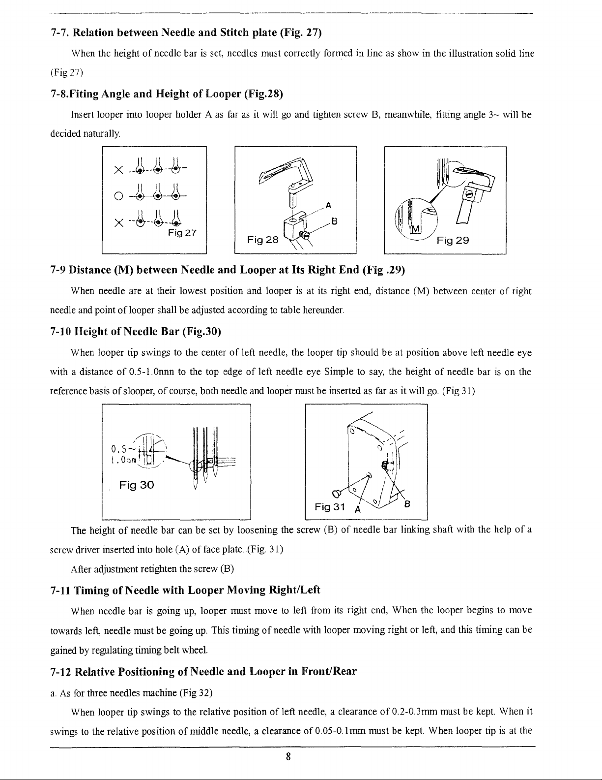
7-7. Relation between Needle
and
Stitch
plate
(Fig. 27)
When the height
(Fig 27)
7-8.Fiting Angle
Insert looper into looper holder A
decided naturally.
of
needle bar
and
Height
X
--~--4--~-
is
set, needles must correctly formed in hne
of
Looper (Fig.28)
as
far
as
it will go and tighten screw
~
0
~
~
~
. FA
X--~--~-~
Fig27
Fig28~
7-9 Distance (M) between Needle
When needle are at their lowest position and looper is at
needle and point oflooper shall be adjusted according
7-10 Height
ofNeedle
Bar
(Fig.30)
and
Looper
at
Its Right
to
table hereunder.
as
show in the illustration solid line
B,
meanwhile, fitting angle
8
End
(Fig .29)
its
right end, distance (M) between center
3~
will be
of
right
When looper tip swings
of
with a distance
reference basis
The height
screw driver inserted into hole (A)
After adjustment retighten the screw (B)
7-11
Timing
When needle bar
towards left, needle must
0.5-l.Onnn
of
slooper,
,
Fig30
of
needle bar can be set by loosening the screw (B)
of
Needle with
to
the center
to
of
course, both needle and looper must be inserted as far
is
going up, looper must move
be
going
of
left needle, the looper tip should
the top edge
of
face plate. (Fig. 31)
Looper
up.
This timing
of
Moving Right/Left
be
at position above left needle eye
left needle eye Simple to
to
left from its right end, When the looper begins
of
needle with looper moving right or left, and this timing can
say,
the height
as
it will
of
needle bar linking shaft with the help
of
go.
(Fig 31)
needle bar
is
to
on the
of
move
be
a
gained by regulating timing belt wheel.
7-12 Relative Positioning
a.
As
for
three needles machine (Fig 32)
When looper tip swings
swings
to
the relative position
of
Needle
to
the relative position
of
middle needle, a clearance
and
Looper
in
Front/Rear
of
left needle, a clearance
of
0.05-0.1 mm must
8
of
0.2-0.3mm must be kept. When
be
kept
When looper tip
is
it
at the
Page 13
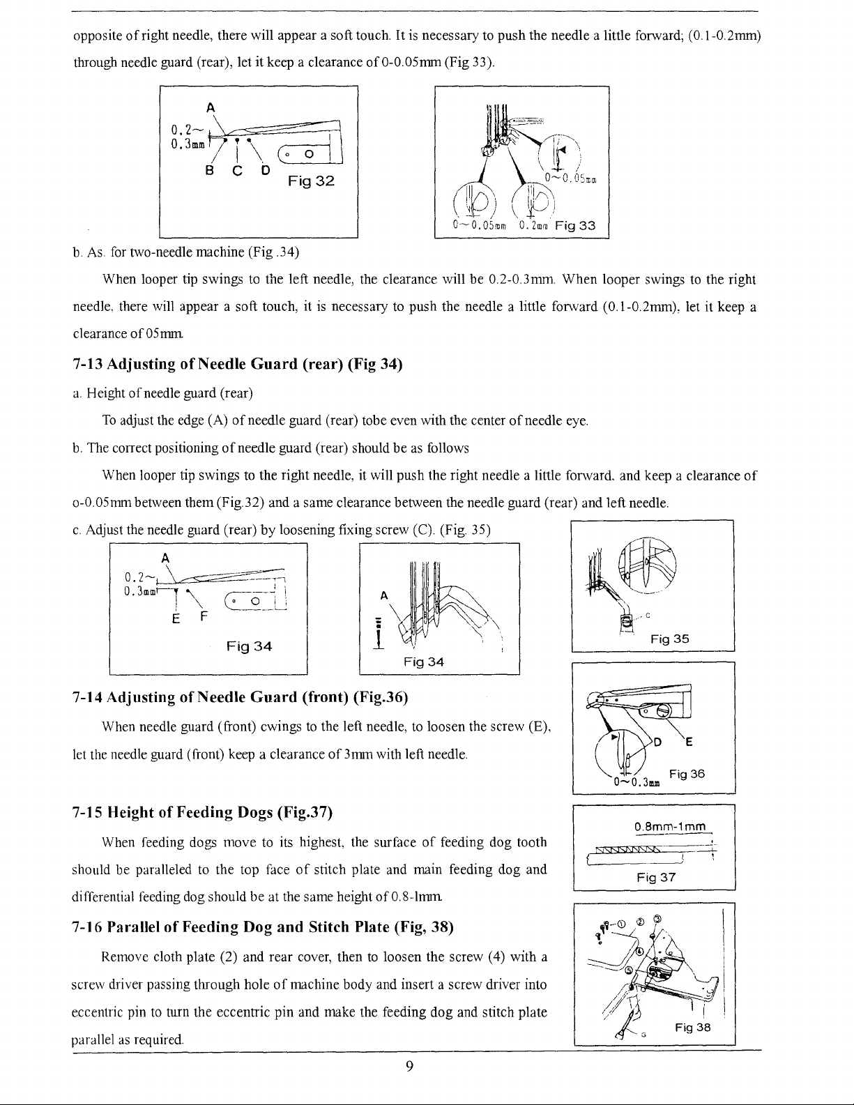
opposite
of
right needle, there will appear a soft touch.
It
is necessary to push the needle a little forward; (O.l-0.2mm)
through needle guard (rear), let it keep a clearance
A
of
0-0.05mm (Fig 33).
u:7f\7~ll
B C 0
b.
As
for
two-needle machine (Fig .34)
When looper tip swings to the left needle, the clearance will be 0.2-0.3mm. When looper swings
needle, there will appear a soft touch, it is necessary to push the needle a little forward (O.l-0.2mm), let it keep a
clearance
7-13 Adjusting
a.
Height
b.
The correct positioning
of05mm
ofNeedle
of
needle guard (rear)
To
adjust the edge (A)
of
of
needle guard (rear) should
Fig32
Guard (rear) (Fig 34)
needle guard (rear) tobe even with the center
be
as
follows
of
needle eye.
to
the right
When looper tip swings to the right needle, it will push the right needle a little forward, and keep a clearance
o-0.05nnn between them (Fig.32) and a same clearance between the needle guard (rear) and left needle.
c.
Adjust the needle guard (rear)
by
loosening fixing screw (C). (Fig. 35)
~~
Fig34
7-14 Adjusting
When needle guard (front) cwings
let the needle guard (front) keep a clearance
7-15 Height
When feeding dogs move to its highest, the surface
should be paralleled to the top face
differential feeding dog should
of
Needle Guard (front) (Fig.36)
to
the left needle,
of
Feeding Dogs (Fig.37)
of
stitch plate and main feeding dog and
be
at the same height ofO.S-lmm
of
3mm with left needle.
AJII~i
- \
- u
.
1
~
' '
Fig34
to
loosen the screw (E),
of
.
.
'\
~.
·,
feeding dog tooth
~.c
NSNSJSNSJSf>
L-----_j
Fig
O.Bmm-1mm
--
Fig
37
35
of
'
--L
~
7-16 Parallel
Remove cloth plate (2) and rear cover, then
screw driver passing through hole
eccentric pin
parallel
as
of
Feeding Dog and Stitch Plate (Fig, 38)
to
loosen the screw ( 4) with a
of
machine body and insert a screw driver into
to
turn the eccentric pin and make the feeding dog and stitch plate
required
9
Page 14
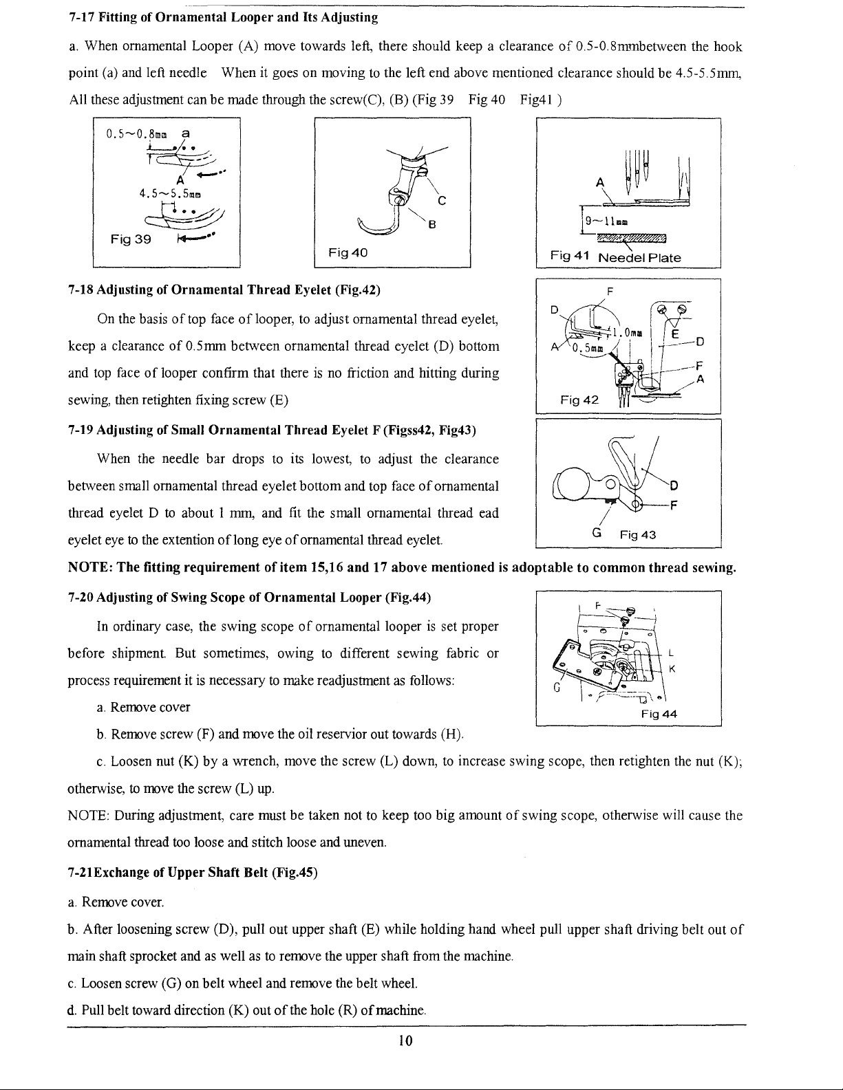
7-17 Fitting of Ornamental Looper and Its Adjusting
a.
When ornamental Looper (A) move towards left, there should keep a clearance
to
point (a) and left needle When it goes on moving
be
All these adjustment can
0.5~0.~
r~..--
A
4.5~5.51!lm
made through the screw( C), (B) (Fig
-··
the left end above mentioned clearance should be 4.5-5.5mm,
39
Fig 40 Fig41 )
of
0.5-0.Smmbetween the hook
A~
~
Fig
39
7-18 Adjusting of Ornamental
On the basis
keep a clearance
and top face
sewing, then retighten fixing screw (E)
7-19 Adjusting of Small
When the needle bar drops
between small ornamental thread eyelet bottom and top face
thread eyelet D
eyelet eye
NOTE:
7-20 Adjusting of Swing Scope of Ornamental Looper (Fig.44)
to
The
f.f-""
Fig40
Thread
of
top face oflooper,
of
0.5mm between ornamental thread eyelet (D) bottom
of
looper confirm that there
Ornamental Thread Eyelet F (Figss42, Fig43)
to
about 1 mm, and fit the small ornamental thread ead
the extention
fitting
oflong
requirement
Eyelet (Fig.42)
to
adjust ornamental thread eyelet,
is
no friction and hitting during
to
its lowest,
eye
of
ornamental thread eyelet.
of
item
15,16
and
to
adjust the clearance
17 above mentioned is
of
ornamental
Fig
D I
Fig
adoptable
E~llmm
*NM((W&&%'%1
41
Needel
Ll.O,u!
42
to common
F
'--'
Fig43
Plate
~
/E_~
0
/...-A
D
thread
sewing.
In
ordinary case, the swing scope
before shipment. But sometimes, owing
is
process requirement it
a.
Remove cover
b.
Remove screw (F) and move the oil reservior out towards (H).
c.
Loosen nut (K)
otherwise,
NOTE: During adjustment, care must
ornamental thread
7-21Exchange of
a.
Remove cover.
b. After loosening screw (D), pull out upper shaft (E) while holding hand wheel pull upper shaft driving belt out
main shaft sprocket and
c.
Loosen screw (G) on belt wheel and remove the belt wheel.
d.
Pull belt toward direction (K) out
to
move the screw (L)
Upper Shaft Belt (Fig.45)
necessary
by
a wrench, move the screw (L) down,
too
loose and stitch loose and uneven.
as
well
as
of
ornamental looper
to
different sewing fabric or
to
make readjustment
up.
be
taken not
to
remove the upper shaft from the machine.
of
the hole (R)
to
keep too big amount
of
machine.
as
follows:
is
set proper
to
increase swing scope, then retighten the nut (K);
Fig44
of
swing scope, otherwise will cause the
of
10
Page 15
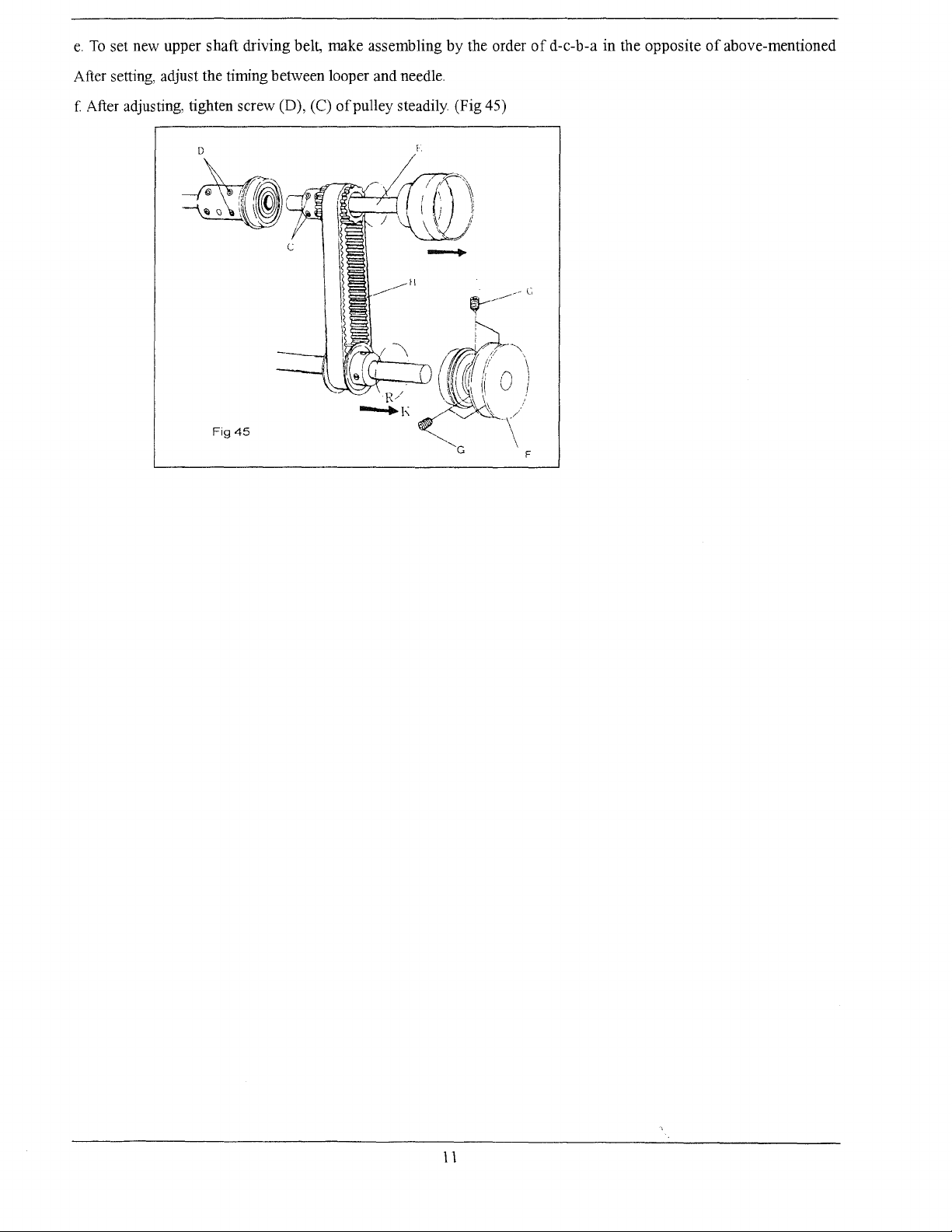
e.
To
set new upper shaft driving belt, make assembling
After setting, adjust the timing between looper and needle.
by
the order
of
d-e-b-a in the opposite
of
above-mentioned
f After adjusting, tighten screw (D), (C)
0
of
pulley steadily (Fig 45)
11
Page 16
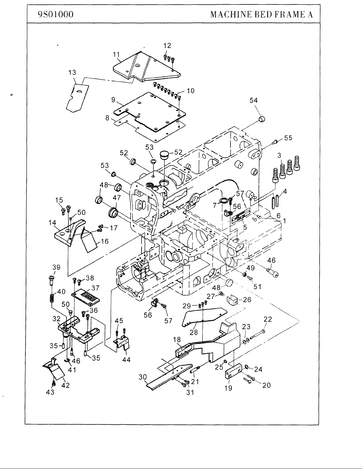
9S01000
13
53
"'
MACHINE
BED
FRAME
55
A
43
Page 17
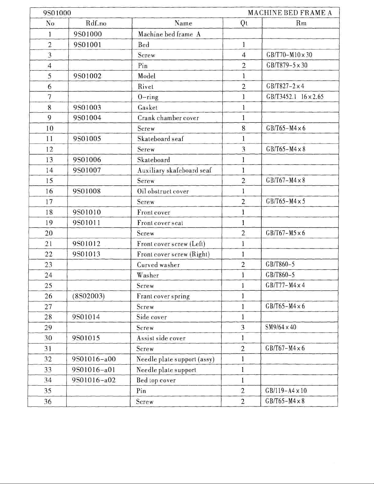
9S01000
No
Rdf.no
Name Qt
MACHINE BED FRAME A
Rm
Machine bed frame A
Screw 4
Pin 2
Model 1
Rivet
0-ring
Gasket 1
Crank chamber cover
7
9
4
5
6
8
1
2
3
9S01000
9S01001 Bed
9S01002
9S01003
9S01004
10 Screw 8
11
12
13
14
15
16
17
9S01005
9S01006
9S01007
9S01008
Skateboard seaf 1
Screw
Skateboard
Auxiliary skafeboard seaf 1
Screw
Oil obstruct cover
Screw
2
2
2
1
1
3
1
1
1
GB/T70-M10x30
GB/T879-5 X 30
GB/T827-2
GB/T3452.1
X 4
16x2.65
GB/T65-M4x6
GB/T65-M4x
GB/T67-M4
8
X 8
GB/T65-M4x5
18
19
20
21
22
23
9S01010
9S01011 Front cover seat
9S01012
9S01013
Front cover 1
Screw 2
Front cover screw
(Left)
Front cover screw (Right)
Curved washer
24 Washer 1
25
26
(8S02003) Franl cover spring 1
Screw
27 Screw 1
Sirle
28
29
30
31
32
33
34
35
36
9S01014
9501015
9501016-aOO Needle plate support (assy) 1
9S01016-a01
9S01016-a02
cover
Screw 3
Assist side cover 1
Screw 2
Needle plate support 1
Bed
Lop
cover
Pin
Screw 2
2
1
1
2
1
1
1
1
GB/T67-M5
X 6
GB/T860-5
GB/T860-5
GB/T77-M4x
GB/T65-M4x
SM9/64 X 40
GB/T67-M4x6
GB/119-A4x
10
GB/T65-M4x
4
6
8
Page 18

9501000
No Rdf.no
37
38
39
40
'9501017
(8510032)
9501018
9501019
41
42
9S01020-b00
43
44
9501021
45
46
47
48
9S01022
9501023
9S01024
49
50
(8510030)
51
52
53
54
(8S03009)
(8S0400
(8503001)
55
56
(8513004)
57
1)
Name Qt
Needle plate
Screw 2
Feed regulating pushbutt
Pushbutton spring
"E"ring
Oil protector plate
Screw
Stuff Obstruct cover
Screw
Screw
Seal plug
Seal plug
Nut
Cushiow rubber
2
2
1
3
1
2
Screw 1
2
2
2
Rivet
1
2
2
MACHINE BED
1
SM9/64 X 40
1
1
1
GB/T896-3.5
1
1
GB/T65-M4x4
1
GB/T68-M3
M4
<(>29.5
<f>20.1x7
GB/T6172-M4
GB/T65-M4x
<(>19
<(>7.5
<!>
10.8
GB/T827-2
GB/T67-M4
X 9
FRAME
Rm
X 9
X 6
16
X 8
X 5
A
Page 19

9S02000
47
1
44
-,
MACHINE
BED
FRAME B
r\?
45
48,~
~
I
:
I
5
15
19
I
1
13
i -
~/v
~
3
30
7~
Page 20

9S02000
No
Rdf.no Name
MACHINE BED FRAME B
Qt
Rm
1
2
9S02000
9S02001
3
4
9S02002
5
6 9S02003
7
8
9
10
9S02004
9S02005
9S02006
II
12
9S02007
I3
I4
9S02008
I5
I6
I7
9S02009
9S020IO
I8
I9
9S020II
20
Machine
Dust
proof
Screw
Pulley
Screw
Side
cover
Screw
Gasket
Side
cover
Side
cover
Screw
Side
cover
Screw
Smail
sewing
Screw
Side
cover
Oil
obstruct
Screw
Silicon
Screw
bed
plate
cover
seat
pin
upper
spring
oil
guide
frame
desk
cover
plate
rack
B
1
3
1
3
1
4
1
1
1
I
1
2
1
2
I
I
I
1
I
GB/T67-M4
X 5
GB/T67-M4 X 50
GB/T65-M4x
GB/T77-M4
GB/T67-M3
GB/T65-M4
GB/T65-M4
GB/T65-M4
10
x 5
X 5
X 5
X 5
X 8
2I
22
23
24
25
26
27
28
29
30
31
32
33
34
35
36
9S020I2
9S020I3-a00
9S02013-a01
9S020I4
9S020I5
9S02016
9S02017
(
8Sl4019)
(
8S14020)
(8S14021)
(
8S14022)
Silicon
Seal
plug
Lower
Lower
Lower
Screw
Screw
Oil
reservoir
Oil
reservoir
Screw
Washer
Press
plank
Screw
Magnet
Screw
Washer
oil
felt
silicone
silicone
silicone
oil
oil
oil
gasket
reservoir
reservoir
cover
inlaid
2
2
4
4
2
I
I
1
1
1
1
1
1
1
1
1
<!>2.5
GB/T65-M4
X 8
SM3/8 X 28
GB/T67-M4x
10
GB/T70-M8 X 25
GB/T848-8-140HV
Page 21

9S02000
No
37
38
39
40
41
42
43
44
45
46
47
48
49
50
51
52
53
54
55
56
57
58
59
60
61
62
63
64
65
66
67
68
69
70
71
Rdf.no Name
Spring washer
il
tube
9S02018
0
Screw
Oil
9S02019
( 9S02022)
9S02020
(8S01001)
(8S01
008)
sight gauge
Screw
Series
Top
cover
sight
Oit
plafe
Screw
Face plate
Screw
Screw
Screw
(8S01
002)
(8SOJ001-a01)
Shoulder
Needle bar take-up cover
Curved washer
(8S01015)
(8S01012)
(8S01
013)
(8S01016)
Needle thread
0-ring
0-ring
Arm
Pin
Washer
(8S01
009-h01) Silicone
Screw
Screw
(
8SO
1009-h03)
Upper
silicone oil reservoir
Screw
Silicone Lake-up bracket
(
8SO 1 009(8S01014)
(8S01
(8S01001-a04)
(8S01001-a03)
(8S0100I-a02)
006)
b04)
Thread guide
Take-up cover screw
Take-up cover
Shelter
Safety
Safety
cover
plate holder
plate support
Screw
(8S01019)
Seal
plug
Screw
Pin
part.i
tion plank
window
screw
oil
thread
guicle
MACHINE BED FRAME B
Qt
2
2
FB/T859-8
1
GB/T67-M4
Rm
X 5
1
1
M4
1
1
1
5
4
2
2
2
GB/T67-M4 X 20
GB/T67-M4 X 20
GB/T3452.1-15x
GB/T65-M4 X 20
GB/T65-M4 X 20
1.8
1
1
1
GB860-87-5
1
1
1
I
2
1
GB119-86
A2x6
GB848-85-4
1
2
2
GB65-M4 X 10
GB65-M4x10
I
2
2
GB67-M3
GB67-M3
X 5
X 5
3
2
1
I
1
I
3
1
1
1
GB80-M3
<!>
8.8
GB80-M4
X 4
X 6
Page 22

8S08000
UPPER SHAFT MECHANISM
/
/ 6
\
15
///
/
I
I
I
L
I
24
Page 23

8S08000
No
1
2
3
4
5
6
7
8
9
10
11
12
13
14
15
16
17
18
I9
20
21
22
23
24
25
26
Rdf.no
8S08001-a00
8S08001-a03
8S08001-a02
8S08002
8S08004
8S06018
8S08006
8S08012
8S08007-c00
8S08009
8S08005
8S08003-b00
8S080I1
8S080IO-d00
(9S03002)
Mction
Screw
Screw
Bsll
Upper
Screw
Upper
Balance
Screw
Joint
Screw
Upper
Ball
Upper
0-ring
Sqrocket
Take-up
Connecting
Screw
Upper
Hand
Washer
Screw
Screw
Screw
Timing
assem
bearing
shoft
shoft(front)
weight(upper)
shaft
bearing
shaft
ball
shaft(rear)
wheel(assy)
belt
Name
bly(assy)
front
middle
middle
wheel(lower)
rod(assy)
bushing
crank
UPPER
Qt
1
2
2
2
1
4
1
1
2
(1)
2
I
2
2
4
1
1
I
4
1
1
1
I
12
1
( 1 )
SHAFT
MECHANISM
Rm
GB/T67-M5X
M6X0.75X
600422
GB/T78-M6X
GB77-85-M5
M6X0.75X
620422
12
12
20X42X12
8
X5
15
20X47X
GB/T3452.1-36.5 X I.
GB/T70-M4X
14
GB/T95-5
GB/T67-M5X
14
GB/T77-M6X5
GB/T77-M6X
8
220XL-075
14
8
Page 24

8S09000
NEEDLE
SPREADER
THREAD
MECHANISM
I
21
23
012
Page 25

8Sll000
No
37
Rdf.no
8S11026
Screw
Name
PRESSER FOOT MECHANISM
Qt
3
SM11/64"X
Hexagon
Rm
40X5-
socket2
38
39
40
41
42
43
44
45
46
47
8S11030
8S
11031
8S11032
8Sl1025
8S
11
034-fOO
Screw
lifter
lever
Screw
Lever
Lever
Nut
Screw
Lever
Screw
Washer
seat
seat bushing
stop
2
2
1
1
1
1
1
1
1
1
SM11/64"X40X
Hexagon
GB/T5781-MSX20
GB/T6170-M5
GB/T70-MSX
GB/T65-M4X
GB/T848-10
12.5-
10
10
Page 26

8Sl2000
THREAD TENSION
\
20
MECHANISM
18
\
/('~
14
/~
16
(1)~
4
( 1 )
1
Page 27

8S12000
No
1
2
3
4
5
6 8512006
7
8512001-aOO
8512002
8512003
8512008
8512005
8512007
8 8512019
9
10
11
12
13
14
15
8512020
8512021
8512011
8512009
8512012
8512014
8512004
16
17
18
8512010
8512013
19
20
21
22
23
8512016
24 8512015
25
26
8512017
8512018
27
28
Rdf.no
Name
Post
nut
(assy)
Spring
Tension
Tension
Screw
bushing
spring
post
stud
Felt
Tension
Thread
Thread
dise
guide
eyelet
Latch
Thread
Tension
Tension
guide
dise
post
Repositioning
Cup
Screw
Tension
dise
Pin
Screw
Screw
Screw
Washer
Collar
Lever
Splashier
oil
Crank
Screw
Pin
collar
plate
pine
separtor
support
spring
eyelet
pipe
THREAD
Qt
5
5
5
5
5
5
10
I
2
2
5
1
I
I
5
2 GBff65-M4 X 8
5
1
2
2 GBff65-M4 X 5
1
I
I
I
I
I
I
I
TENSION
cpl
x3,
GBff65-M4
GBff65-M4
GBff97.1-8
GBff70-M5 X
GBff119-D5 X
MECHANISM
Rm
cp0.6x2
X 8
X
16
16
18
Page 28

9S03000
MAIN
SHAFT
22
AND
LOOPER
THREAD
MECHANISM
4
29
61
62
63
64
35
65
45
41
Page 29

9S03000
No
1
Rdf.no Name
Main
9S03000
shaft
and
looper
MAIN
thread
SHAFT
mechanism
AND
LOOPER
Qt
THREAD
MECHANISM
Rm
2
3
9S03001-a00
9S03001-a01
Sprocket wheel
Sprocket wheel
asm
4 Screw 1
5
6
7
8
9
10
11
12
9S03001-a02
9S03002
9S03003
9S03004
9S03005
9S03006
Ward slice
Upper Sprocket wheel
Screw 4
Timing belt
Balance weight
Screw
Lower shaft (Right) 1
Joint
13 Screw 2
14
15
9S03007 Lower shaft
16 9S03008
17
9S03009
18 9S03010 Oil wick
Screw 2
(Left)
Oil wick (Left)
Oil wick (Short)
(Long)
19 9S03011 Oil wick (Short)
20
21
22
23
24
25
26
9S03012
9S03013
9S02014-b00
9S02014-b01
9S02014-b02
9S02014-b03
Lower bushing (Center)
Large
ward
plate
Screw
Pulley wheel (assy)
Pulley wheel
Sprocket wheel
Sprocket wheel
key
1
1
2
1
1
1
2
1
1
1
5
2
1
1
1
2
1
1
1
1
GB/T80-
M6
GB/T80-M6
220XL-075
GB/T80-M5
GB/T80-M5
GB/T80-M5
4>2x3
4>2x
60
4>
2 X
15
GB/T67-M4
X 5
X 5
X 5
X 4
X 5
X 6
27
28
29
30
31
32
9S02014-h04
9S03015
9S03016-c00
9S03016-e01
9S03016-c02
Screw
Screw
Timing belt
Sprocket wheel (assy) 1
Cam
sproeket_wheel
Ward slice
33 Screw
34
35
36
9S03017
9S03018
9S03019
Cam
shaft
Wasket 2
Ball bearing
2
2
1
1
1
1
1
1
M6
GB/T80-M6
GB/T80-M5
6200ZE
4>30 X 4>
X 6
X 6
10
X 9
Page 30

9503000
No
MAIN
Rdf.no Name
SHAFT
AND
LOOPER
Qt
THREAD
MECHANISM
Rm
37 9S03020
38 9S03021
39
40
41
42
43
44
45
46
9S02022
( 8S07005)
9S03023
9S03024-d00
9S03024-d01
9S03024-d02
9S03025
9S03026
47 9S03027
48
49 9S03028
50
51
52
( 8S13005)
(8S13010)
53
54
55
56
57
58
(8S09010-c03)
(8S090 1 O-c04)
(8S090 1 O-c05)
(8S090 1 O-c02)
59
60
61
9S03029-e00
62 9S03029-e01
63
64
9S03029-e02
9S03029-e03
65
66
9S03030
67
68
( 9S05016)
69
70 (8S060
11-eOO)
71
72
0-ring
Cam
bushing
Collar
Screw
Lower thread guide
Left thread bracket
Thread guide pad guide
Lower
Screw
Wasket
Adjusting thread plate
Screw
Lock
Screw
Right thread guide
Left thread guide
Wasket
Screw
Screw
Nut
Tension spring
Tension disc
Screket
Wasket
Looper thread
Looper thread
PartiLing collar
Cam
Screw
Small
Screw
Oil Seal
Screw
Worm
Ball bearing
0-ring
thread bracket
spring
cam
cam
disc bushing
Guard
asm
(assy)
disc
2
2
1
2
1
1
2
1
1
2
1
2
1
1
1
1
2
2
1
1
2
1
1
1
1
1
1
1
1
1
1
1
1
1
1
cj>28.7 X cj>
SM1/8x44
M4
(GB/T955-6)
GB/T65-M4
GB/T65-M4
GB/T848-2.5
GB/T65-M2.5
GB/T67-M4
GB/T848-4
GB/T80-M5
GB/T67-M4
GB78-85-M6
6200ZZ
GB/T80-M6
1.3
X 4
X 4
X 8
X 6
X 6
20 X 52 X 15
X 5
X 4
x 6
Page 31

8S09000 NEEDLE SPREADER THREAD MECHANISM
No
1
2
3
4
5
6
7
8
9
10
1 1
12
13
14
15
16
17
18
19
20
21
22
23
Rdf.no
8S09004
8S09005
8S09006
8S09007
8S09008-b00
8S09002
8S09003
8S09001-a02
8S09001-a01
8S09001-a03
8S09010-c06
8S090
10-cO
8S09010-c03
8S09010-c02
8S09010-c05
8S09010-c04
8S09009
Driving
Rear
Collar
Front
Oil
seal
Thread
Screw
Thread
Washer
Screw
Washer
Screw
Thread
Thread
Bracket
Top
cover
Supplementary
1
Tension
Tension
Tension
Nut
Scrlew
Thread
bushing
Name
shaft
bushing
set
(assy)
guide
guide
take-up
take-up
thread
post
disc
spring
guide
guide
thread
guide
Qt
1
1
1
1
2
1
5
1
1
1
4
4
1
1
1
1
1
1
2
1
1
I
1
Rm
GB/T65-M4X6
GB/T93-5
GB/T70-
:\15 X 16
GB/T97.1-4
GB/T65-M4X
10
SM9/64"X40
GB/T65-M4X6
'
Page 32

8S10000
4
\.
NEEDLE
BAR
MECHANISM
/
16
19
/
\
22
\
24
52
\
2
Q
"---56
I
31
38
Page 33

8SIOOOO
No
1
2
3
4
5
6
7
8
9
10
11
12
13
14
15
16
17
18
19
20
21
22
23
24
25
26
27
28
29
30
31
32
33
34
35
36
37
Rdf.no
8S
10011
8S10025
8S10003
8S10006
8S10007
8S10009
8S10010
8S10008
8SI0002
8S10023
8S10014
8S10038
8S10012
Driving shaft 1
Catch 1
Driving shaft bushing(left) 1
Screw
Oil wick
Screw
Screw
Adjusting lever
Driving
Collar
Screw
Screw
Nut
Washer
Rocking arm
Rocking
Screw
Thread
Needle
Crankshaft
Name
shaft bushing( right)
pin
guide
bar
8Sl0005 Connecting rod
8S10004
8S10027
8S10024
8S10022
8SI 0039
8S10028
8SI0029
8S10036
8S10034
Eccenting cam
Spreader
Oil seal
0-ring
Collar
Screw
Screw
Screw
Oil wick
Spieader
Spieader
Screw
Needle
Thread
Needle
Needle clamp
bushing
holder
guide
clamp eyelet
NEEDLE
Qt
2
1
1
1
I
1
I
1
2
1
1
1
1
2
2
1
1
1
1
1
1
I
1
2
1
1
1
1
1
1
3
1
1
1
BAR
MECHANISM
Rm
GB/T119-D5X14
GB/T80-M6X6
¢3X
15
GB/T67-M3
GB/T77-M5
M6
0.75X
X6
X4
15
GB/T6170-M5
GB/T95-5
GB/T65-M4X10
GB/T3452.1-10.6X
GB/T80-M4X4
SMII/64"
40X
10.5
GB/T70-M5X12
¢3X
15
SMI/8"44X4
UYI28GAS-11
4.8,5.6,6.4
1.8
Page 34

8S10000
NEEDLE
BAR
MECHANISM
No
38
39
40
41
42
43
44
45
46
47
48
49
50
51
52
53
54
55
56
57
58
Rdf.no
8S10019
8S10018
8S10017
8S10016
8S10035
8S10021-a00
8S10020
8S10040
8S10046
8Sl0044
8Sl0042
8S10043-b00
8Sl0045
8S10013
8S10015
8S10026
ScrewApring
Latch
Thread
Screw
"E"ing
Oil
Needle
Needle
Needle
Connecting
Connecting
Needle
Needle
Oil
Screw
Needle
Ncrew
Sponge
Screw
Washer
guide
ring
bar
bar
bar
bdaring(assy)
bdearing
wick
plate
bar
Name
bushing
bracket
bushing(upper)
rod
rod
guide
(lower)
pin
washer
Qt
1
1
1
1
4
1
1
1
1
1
1
1
1
1
1
3
1
1
1
2
1
Rm
SMl/8"44-(1.58)
Hexagon
GB/T895.1-12
Kt8X
GB/T65-M4Xl2
GB/T65-M4X5
GB/T77-M5X5
GB/T861.2-3
socket1.58
12X
12
Page 35

8S11000
1
PRESSER
FOOT
MECHANISM
8
__
.-12
I
13""~
I
22
Page 36

8SIIOOO
PRESSER
FOOT
MECHANISM
1---·
No
IO
11
12
13
14
15
I6
I7
18
19
20
21
22
23
24
25
26
27
28
29
30
31
32
33
34
35
36
6
7
8
9
2
3
4
5
1
Rdf.no Name
8S
11001
8S
11002
8S
11
004-aOO
8Sll
005
8S11012
8S11003
8S11006
8S11011
8S110IO
8S11008
8S11009
8S1I013-h00
8S11014
8S11015
8S
I1
007
8S11016
8S1I017-cOI
8S
11017
-cOO
8S110I8-d00
8S11019
8SI1020
8S1I021
8S
11022
8SII023
8SI1029
8S
I1
024
8S
11
033
-eOO
8S
11
033
-e02
8S11028
8S11027
Adjusting
Lock
nut
Presser
Screw
Pin
Shouider
Outer
Presser
Lifter
Screw
Screw
Inner
Oil
Presser
Oil
Collar
Screw
Presser
Finger
Screw
Presser
Screw
Lifter
Pin
Spring
Collar
Screw
Rubber
Caller
Washer
Lifter
Lever
Interrupt
Screw
Correcting
Shouider
spring
link
spring
protector
seal
guard
shaft
lever
Screw
bar
guide
Screw
bar
clamp
ring
bar
bushing
bar
foot
complete(assy)
(assy)
washer
lump
plate
Screw
(assy)
Qt
1
1
1
1
1
2
1
1
I
2
1
1
1
1
I
I
2
1
1
I
1
1
1
1
1
1
2
2
I
2
2
1
1
1
I
2
Rm
M16XI
MI6XJ
SMI
J/64"X40
GB/T879-3X
SM3/16"X32
GB/T65-M4X20
GB/T70-M5X8
SM/8"
X 44-( I
Hexagon
SM9/64" X 40X8
GB/T65-M3X6
GB/T879-4X
SM9/64"X
GB/T97.
SMI
1/64"X40X8
SMII/64"X40
12
.58)
socketl.58
16
40X6
I -4
Page 37

9S03000
No
MAIN
SHAFT
AND
LOOPER
Rdf.no Name Qt
THREAD
MECHANISM
Rm
73
74
75
76
77
78
79
Screw
9S03031 Lower shaft bearing (Right)
0-ring
8S06014-h00
Lower shaft bearing (Rear)
Ball bearing
Thrust coller
Screw
4
1
2
1
2
1
1
GB/T80-M6
6004ZZ
X 5
20 X 42 X 12
GB/T4352.1-31.5 X 1.8
6304ZZ
GB/T80-M6
20 X 42 X 12
X 5
Page 38

9S04000
36
i
~
33
'
LOOPER
\
MECHANISM
26
-
11
9
~
~10
'
24
41
47
50
47
Page 39

9S04000
No
Rdf.no
Name
Qt
LOOPER
MECHANISM
Rm
5
6
7
8
9
IO
11
12
13
I4
15
16
17
18
I9
20
2I
22
23
24
25
26
27
28
29
30
31
32
33
34
35
36
2
3
4
1
9S04000
9S04001
9S04002
9S04003
9S04004
9S04005
9S04006
9S04007
9S04008
9S04009
9S04010
9S040
11
9S04012
9S040I2
9S04013
9S04014
9S04015
9S040I6
9S04017
9S04018
9S04019
Looper mechanism
Looper
Screw
Looper Seat
Screw
Gasket
Looper seat shaft
Bushing
Screw
Looper thread eyelet
Screw
Oil pipe
Oil wick
Washer
Looper front
rear
rocker
Slider holder
Screw
Slider
Screw
Screw gasket
Reduce gasket
Reduce
Reduce gasket
washer
holder
Screw
Bushing
Screw
Pin
Pin
Screw
Washer
Nut
Washer
Looper rocker
connecting
Needle bearing
Eccentric
Screw
roc
2
2
2
1
1
1
1
I
1
1
1
1
1
1
1
1
1
1
1
1
1
1
1
1
1
1
I
1
1
1
I
1
1
1
1
GB/T70-M4x
10
GB/T80-M6x6
GB/T67-M4x
GB/T879-
<j>
3 X
50
<P
5
4 X
GB/T67-M4 X 12
GB/T80-M4
GB/T67-M4x
X 4
12
GB/T80-M6x6
GB/T879-
<P
1.5
GB/T67-M5 X 30
GB/T6175-M5
GB/T972-5
26 X 30 X 12.5
GB/T80-M5
X 5
14
X 4
Page 40

9504000
No
Rdf.no
Name
Qt
LOOPER
MECHANISM
Rm
37
38
39
40
41
42
43
44
45
46
47
48
49
50
51
52
53
9504020
9504021
9S04022
9S04023
8S06006-b01
9S04024
9S04025
9S04026
9S04027
9S04028
9504029
9504030
9504028
( 9SOI
024)
Looper Connecting rod
Screw (upper)
Oil splasher
Screw (Lower)
"U" Guide fork
Screw
Looper ball crank
Screw
Looper rocker bar
Screw
Thrust roller bearing
Thrust plate
Looper shaft
Front bushing
Rear bushing
Oil wick
Oil plug
2
2
2
3
2
1
1
1
1
1
1
1
1
1
1
1
1
GB/T67-M3
GB/T70-M6x
X 6
0.75 x 10
GB/T70-M6 X 0.75 X 14
<j>4x
100
<j>20.1x7
Page 41

9S05000
DIFFERENTIAL
CONTROL
4
MACHANISM
~8
20 I ' 15
'I / /
!::J
~·
"""',
~'
/
J,
it19
(.,/
~
21
4>r
//
...
,,
/<
\J
-u-
16
-23
/
.
:v//13
/
/h/~
,'
_______
/
--·
/~
/
~r
14/
~
2
7
~~
~~
"
:e/
~//-
/J;q
--9
.··
-
is
1
>
4
44
47
~
46
Page 42

9S05000
No
Rdf.no
Name
DIFFERENTIAL CONTROL MACHANISM
Qt
Rm
1
2
3
4
5
6
7
8
9
10
I 1
12
13
I4
15
16
17
18
19
20
21
22
23
24
25
26
27
28
29
30
9S05000
9S05001
9S05002
9S05003
9S05004
9S05005
9S05006
9S05007
9S05008
9S05028
9S05009
9S050IO
9S05011
9S05012
9S05013
9S05014
9S05015
9S05016
9S05017
9S05018
9S05019
Differential control machanism
Differential feeddog
eccentric
Screw
Needle
Differential feed
bearing
link
"E"ring
Pin
Differential
feed
link
(Lever)
Screw
Differential feed
link
(short)
Pin
Differential
feed
crank
Screw
"E"ring
Connecting
Differential
rod guide
regulating
seat
Screw
Return
spring
Pin
Screw pin
Regulating
plate
Screw
Pin
Bushing
0-ring
Oil seal
set
Screw
Regulating
seat shaft
Washer
Differential
regulating
3
1
1
2
1
1
1
1
2
2
2
2
2
1
1
1
1
1
1
I
I
I
1
1
1
1
1
I
I
GB/T77-M5
X 6
25 X 29 X 10
GB/T894.1-25
GB/T80-M4
X 5
GB/T65-M5 X 12
GB/T80-M5
GB/T67-M4
GB/T879-3
X 5
X 6
X 4
GB/T3452.1-15 X 2.65
GB/T77-M6
X 8
31
32
33
34
35
36
9S05020-a00
9S05020-a01
9S05020-a02
8S04012-b00
(
8S04013)
Differential
Differential
Washer
Screw
Nut
Screw
regulating
regulating
craduations(assy)
craduations
2
2
1
1
1
1
GB/T67-M4x
12
Page 43

9S05000
No
37
38
39
40
41
42
43
44
45
46
47
48
49
50
51
Rdf.no
(
8S040
9S05021
9S05022
9S05023
9S05024
9S05025
9S05026
9S05027
14)
Conical
Feed
spring
lift (Large)
Pin
Screw
Raise
Feed
crank
Screw
Screw
bushing
Nut
Screw (Lever)
Pin
Screw
Nut
Screw
Washer
Conical
spring
DIFFERENTIAL CONTROL MACHAl\ISM
Name Qt
washer
1
1
1
1
1
2
1
1
1
1
1
1
2
2
washer
1
Rm
GB/T80-M4
GB/T77-M5
GB/Tl19-D4 X 12
GB/T77-M3
GB/T67-M4x
GB/T97.1-4-140HV
X 5
x 5
X 6
10
Page 44

9S06000
FEED
REGVJIATING
58/'~
_/~-57
#-60
-59
MECHANISM
31
56
,19
/
50
18
Q-72
10
12
\
\
Page 45

9S06000
No
1
2
3
Rdf.no
9S06000
9S06001
9S06002
4
5 9S06003
6
9S06004
7
8
9
10
9S06005
11
12
13
14
15
9S06006
9S06007
9S06008
9S06009
16
17
18
19
9S06010
9S06011
20
21
22
9S06012
9S06013
23
24
25
26
27
28
9S06014
9S06015
9S06016
9S060I7
9S060I8
29
30
9S06019
3I
32
33
34
35
36
37
38
9S06020
9S06021
9S06022
9S06023
9S06024
9S06025
9S06026
Name
Feed
regvjiating
Right
Bushing
raise
collar
bushing
Screw
Left
raise
bushing
Raise
shaft
Oil wick
plug
Seal
Short oil wick
Feed
lift
block
Oil wick
Bushing
(Right)
Collar
Bushing
Differential
(Left)
feed shaft
Oil wick
Oil wick (short)
Differential
felL
Oil
small
Pin
Adjusting
eccentric
Lever Screw
Washer
Differential
Differential
Feed
dog key
feed
feed
Screw
Feed
bar
guide
Screw
Feed
bar
guide
Screw
Main feed
bar
Main feed dog
Feed
bar
guide
Feed
bar
black
Feed
small
link
Screw
Feed
small
link
mechanism
(Front)
link
bar
dog
(Lower)
(Left)
(Right)
(Rear)
bushing
FEED
REGVJIA TING MECHANISM
Qt
I
Rm
3
4
GB/T80-M5
X 4
1
I
I
<I>
2 X
320
1
I
<1>2 X 10
1
1
<1>2 X 15
1
1
I
1
2
2
<1>2 X 320
<1>2 X 10
1
1
2
GB/TI
19-AI X 5
1
1
2
1
SMII/64" x40x
GB/T97
.1-4-I
40HV
19
1
2
2
SM9/64" X 40
I
2
GB/T67-M4 X 10
1
2
GB/T77-M6
X 8
1
1
I
I
I
I
1
SM
I l/64 X
40
X I 7
Page 46

9S06000
No
Rdf.no Name
FEED
REGVJIATING
Qt
MECHANISM
Rm
39
40
41
9S06027
9S06028-a00
9S06028-a01
42
43 (
44
45
46
47
48
49
9S06028-b00
9S06028-b01
9S06028-b02
9S06028-c00
9S06028-c01
50
51
52
9S06028-b03
9S06028-b04
(
8S05009)
8S05008)
(
8S05007)
Oil felt
Feed
Regulator
Screw
Screw
Screw
Feed
Pin
Feed
Feed
Feed regulating eccentrc
Pin
Spring washer
Spring washer
53 Screw
54
55
9S06028-b05
Feed regulating restrict plafe
Res !ric t plafe pin
56 Screw
57
58
59
60
61
62
63
64
65
66
67
68
69
70
71
72
73
74
75
9S06029
9S06030
9S06031
9S06032
9S06033
9S06034
9S06035
9S06036
9S06037
9S06038
9S06039
Needle guard eccentrc (Front)
Screw
Needle guard forked (Front)
Screw
Needle guard forked (Rear)
Screw
Washer
Needle guard holder (Rear)
Needle· guard lover (Rear)
Screw
Needle guard (Rear)
Screw
Needle guard holder (Front)
Needle guard (Front)
Pin
Screw
Oil wick
Front shaft
Needle guard shaft
eccentric
eccentric
(assy)
(Small assy)
eccentric
regulating eccentrc (assy)
presser
2
1
1
1
1
1
1
1
1
1
1
2
1
1
1
1
2
1
1
I
1
2
1
1
1
1
2
1
1
1
1
1
1
1
1
1
1
M3x3
GB/T119-D2
SM3/32 X 56
GB/T879-Dl.5
SM9/64 X 40
GB/T77-M5
SM9/64 X 40 X 12
SM9/64 X 40 X 12
GB/T848-6-300HV
GB/T80-M4
SM9/64 X 40
GB/T80-M4
_<j)
3 X
15
X 9
X 4
x4
X 6
X 5
X 4
X 6
X 4
Page 47

8S14000
35
'\
9
/t'%'F
51
LUBRICATION
4
50
49
'JO
lf2
MECHANISM
/11
,..,..---1
_.,..---14
47
/
46
13
-~
\
20
43
Page 48

8S14000
No
1
2
3
4
5
6
7
8
9
10
11
12
13
14
15
16
17
18
19
20
21
22
23
24
25
26
27
28
29
30
31
32
33
34
35
36
37
Rdf.no
8S14005-c07
8S14005-c06
8S14005-c04
8S
14005-cOl
8S14005-c05
8S14005-c08
8S14005-c03
(9S02018)
8S14023
8S14005-c02
8S
14021
8S14022
8S14019
8S
14020
8S14014
8S
14013
8S14012
8S14010
8S14009-e00
8S14008
8S14001-a02
8S14007
8S14025
8S14024
8S14002
8S14003
Pump
Pump
Pump
Pump
Screw
Screw
Worm
Screw
Bracket
Screw
Pump
Oil
Screw
Pump
Screw
Press
Magnet
Screw
Washer
Screw
Joint
Clamp
Oil
Screw
Nut
Screw
Qil
0-ring
Oil
Screw
Oil
Oil
Screw
Pipe
Ring fer
Oil
Latch
inner
gear
shaft
cover
body
tube
body
plank
tube
filter
filter
tube
guard
felt
gear
wheel
1
partition
2
spring
set (assy)
cap
press
hole
Name
plank
plank
LUBRICATION
MECHANISM
Qt
1
1
1
1
2 GB/T70-M4 X 42
2
1
2
1
2
1
( 1 )
( 2 )
1
2
1
1
1
1
3
5
7
1
3
1
1
1
1
I
3
2
1
1
1
( 1 )
1
1
GB/T70-M4X42
GB/T70-M4
GB/T80-M4X4
GB/T70-M6X 12
GB/T67-M4X5
GB/T65-M4X
SM3/8"X28
SM1/4"X40
¢6
X 1
X480
GB/T65-M4X
GB/T6170-M4
M10X 1
GB/T3452.1-38.7 X 2.65
GB/T65-M4X
GB/T77-M4X
¢8X1
GB/T895.1-16
Rm
X 25
10
6
16
16
Page 49

8Sl4000
No
38
39
40
41
42
43
44 8S14004-h02
45
46
47
48
49
50
51
52
Rdf.no
8S
14006-
8S14011-f00
8S14004-b00
8S14015
8S14001-a00
8S14026
8S14115-c09
8S14005-cl0
(
8503012)
9502019)
(
dOO
Name
Oil distributor(assy)
Oil tube
Non-return valve(assy)
Oil nozzle for
worm
gear(assy)
Oil tube
Screw
Nut
Looper oil distributor(assy)
Oil tube
Oil pipe
Looper oil tube
Latch
Oil filter screen
Oil filter
Oil sight Gauge
LUBRICATION
Qt
1
1
1
1
1
1
1
1
1
1 <j>4X0.5X80
1
1
1
( 1 )
( 1 )
<!>
6X 1 X340
<!>
6X 1 X340
SM1/4"X40
SM1/4"X40
<j>6X1X35
<j>6X 1 X260
GB73-85-M8X4
MECHANISM
Rm
Page 50

9S07000
SPECIAL
TABLE
COMPONENTS
-
---
.....--
---
.....--
.....--
---
-
-~
--
5~t
4-----
3------
0
0
0
0
Page 51

9S07000
No
Rdf.no
Name
SPECIAL
Qt
TABLE
COMPO!\El\TS
Rm
1
2
3
4
5
6
7
8
9
10
11
12
9S07000
9S07001
9S07002
(8S15004)
(8S15002)
Special table components
Oil reservoir screw
Oil reservoir nul
Spring washer
Washer
Pulley cover
Tapping screw
Block chain guard
Tapping screw
Vibration-proof rubber pad
Table
"L"machine stand (assy)
4
4
4
4
4
1
3
1
2
1
M8
M8GB/T41-M8
GB/T93-8
GB/T96-8
GB/T845-ST4.8 X 13
GB/T845-ST4.8 X 13
I
I
I
:
'
I
I
I
I
'
Page 52

8S15000
TABLE COMPONENTS
Page 53

8Sl5000
TABLE
COMPONENTS
No
I
2
3
4
5
6
7
8
9
IO
11
Rdf.no
8SI5003
(9SI500I)
8SI5004
8SI5002
8SI500I
Name
Serew
serew
Supporting
Block
Nut
Aam
rubber
Duter
Vibration-proof
Screw
Table
"L"
board
chain
guard
cushion
washer
machine
rubber
stand
pad
(assy)
Qt
4
4
2
I
4
4
12
4
2
1
I
Rm
GB/TI4-M8X
GB/TI4-
GB/T96-8
GB/T70-M5X8
1200X
XM8
540 X 50
80
Page 54

9S08000
5
PACKAGE
COMPONENTS
2
J
7
Page 55

9508000
No
1
2
3
4
5
6
7
8
Rdf.no
9508001
9508002
9508003
9508004
9508005
Name
Machines head packing
Machines head accessories
Top
cover
Bottom bracket
End pad
Guard against pad (Front)
Guard against bracket (Rear)
Box
lining
box
box
PACKAGECOMPONENT5
Qt
I
1
GK008
GK008
Rm
1
1
1
I
1
1
Gk008
Page 56

8Sl6000
MACHINE
HEAD
ACCESSORIES
-----
1 0
4 5
/ I 6
~
3
15
~2
14
/,
Page 57

8S16000
MACHII\E
HEAD
ACCESSORIES
No
1
2
3
4
5
6
7
8
9
10
11
12
13
14
15
I6
17
I8
Rdf.no
8S16001
8S16002
8SI6003
8S16005
8S16006
Operation
Oil
funnel
Oil
reservoir
Double-head
Double-head
Double-head
Screw
Screw
Thread
manual
driver
driver
tweezers
Chain
Allen
wrench
Oil
filter
8S
14009-eOO
8S16007
Arm
set
cover
Needles
8S16008
Small
Silicone
oiler
oiler
Peddle
8S16004 Allen wrench
Name
wrench 1
wrench
wrench
Qt
I
I
I
I
I
1
I
I
I
6
I
I
IO
I
I
I
2
Rm
1
OOOml
6(mm)
7 ( mm)
8 ( mm)
I10 ( mm)
200 ( mm)
90mm
950mm
1.5,2,2.5,3,4,5,(mm)
LTI28GAS-70-75
( 128GAS-#10-11)
50ml
1116"(1.588)
Hexzgonl.588
Page 58

Page 59

Page 60

SHANGHAI
HUIGONG
N0.3
SEWING MACHINE FACTORY
ADD: 1418,
Yishan
Road,
Shanghai,
China
Zip Code: 201103
Overseas
Business:
E-mail:highlead@online.sh.cn
The
description
TEL:
covered
86-21-64853303 FAX: 86-21-64854304
http://www.highlead.com.cn
in
this
manual
is
subject
to
change
for
improvement
of
the
comnHHlity
without
2004.2.
notice
Printed
 Loading...