

Page 1
..
Purchasing
HIGHLEAD
GG0068
-1
Dept
Copy
High-Speed,1-Needle,Lockstitch, Zigzag Stitching Machine
In struction Manual
Pa
rt
s
Catal
og
•
SHANGHAI HUIGONG
N0.3
SEWING
MACHINE FACTORY
Page 2

CONTENTS
CONTENTS •••••••••••••••••••••••••••••••••••••••••••••••••••••••••••••••••••••••••••••••••••••••••••••••••••••••••••••••••••••• 1
1,
PRECAUTIONS
2,
MAIN SPECIFICATIONS
3,
PREPARATION AND LUBRICATION ••••••••••••••••••••••••••••••••••••••••••••••••••••.••••••••••••••••••••••••••• 2
4,
REPLACE NEEDLES
5,
WINDING
6,
THREADING
.._
ADJUSTING
7
8,
ADJUSTING
9,
ADJUSTING
10
...
ADJUSTING
11,
ADJUSTING
12
...
ADJUAT
THE
THE
THE
THE
THE
BEFORE
BOBBIN
THE
MACHINE
STITCH
HEIGHT
PRESSURE
THE
THE
BOBBINTHREADTENSION
ZIGZAG
STARTING
..................................................................................................
••••••••••••••••••••••••••••••••••••••••••••••••••••••••••••••••••••••••••••••••••••••••••••••••••••••••••••••••••.••••••••••••••••••
THREAD
LENGTH
OF
THREAD
WIDTH
•••••••••••••.....•••••••.••••••••••••••••••.•.•.•••••••••••••..•.•••••••••••••••.•....•.•••••••••.••...•••••
HEAD
THE
OF
THE
TENSION
••••••••••.•.••••....••.••..•••••••••••••••••••••.•......••••••••••••.•..•••••.••......••.•••.....••••••••••••••
OPERATION
••••••••.••..••••••••••••••••••••••••••••••••••••••••••••••••.•••••••••••••.•...•..•••••••••••••••••••.•
.••••••••••••••••••••.•••••••••••••••••••••••••••••••••••••.••.•••••••••••••••••.....••••••••••••••••..••
PRESSER
PRESSER
.•.•••...•....•.•••••••••••.•.•.........••••••••••••..••••••••••••••••••••••••••.•••••••••••
..... , .......................................................
3
3
4
5
....................................................................................... 5
FOOT
................................................................
......................................................
5
5
6
6
2
2
13,
ADJUSTING
14
...
ATTACHING/REMOVINGTHEHOOK
15
...
ADJUST
16
...
ADJUSTING
17,
ADJUSTING
18,
ADJUSTING
19
...
CHANGEOVER
20,
PLACING A BOBBIN
PARTS CATALOG .•...•...•..•..••••••••••••••.••••.••.••••••••••.•.•••••••••.•..•..••.•.•••••••.••••••••••....•.•••••••.••. 10
THE
THE
HEIGHT
THE
THE
DENSER
POSITION
OF
NEEDLE
AMOUNT
OF
STANDARD
INTO
STITCHING
OF
FEED
THE
NEEDLE BAR
TO
HOOK
OF
OIL
ZIGZAG
THE
BOBBIN
.............................................................................................. 7
.•.•.••••••••••••••••••••••••••••••••••••••••••••••••••••••••••••••••••••••••••••.•••••••••••••
DOG
•.•.••••••••••••••••••••••••.••..••••••••••••••••••••••••••••••••••.••••••••.•••••.•••••••••••
••••••••••••••...••••••••••••••••••.•..•..••••••••....••••••••••••••.•.••••••••••••••
TIMING
IN
THE
AND
THE
NEEDLE
HOOK
.•••..•••••••••••••••••••••••••••..••••••••.••••••.•••••••••••••.•...•.•..•••••.•.•••.••••••
CASE
............................................................................ 8
................................................................................... 9
GUARD
.............................. 8
7
7
8
9
-1
Page 3
1.
PRECAUTIONS
1)
Safety Precautions
(I)
When turning the power on, keep your hands and fingers away from the area around/under the needle
and the area around the balance wheel.
(2) Power must be turned
(3) Power must be turned
the machine,
(4) Avoid placing fingers, hairs, bars etc., near the balance wheel,
or motor when the machine
(5) Do not insert fingers into the thread take-up cover, under/around the needle,
machine
If a belt cover, finger guard, eye guard are installed, do not operate the machine without these safety
(6)
devices.
2) Precautions before Starting Operation:
(I)
If the machine's oil pan has an oil sump, never operate the machine before filling it.
(2) If the machine
(3) When a new sewing machine is first turned ·on, verify the rotational direction
the power on. (The balance wheel should rotate counter-clockwise when viewed from the balance wheel)
(4)
Verify
is
in
the voltage and (single
BEFORE
off
when the machine
off
when tilting the machine head, installing or removing the
or
when replacing.
operation.
is
lubricated by a drop oiler, never operate the machine before lubricating.
STARTING
is
is
in operation.
or
three) phase with those given on the machine nameplate.
OPERATION
not in use,
or
when the operator leaves the seat.
"V"
belt, bobbin winder balance wheel,
or
of
balance wheel when the
"V"
belt, adjusting
the balance wheel with
3)
Precautions for Operating Conditions:
(I)
Avoid using the machine at abnormally high temperature (
lower) .
(2) Avoid using the machine in dusty conditions.
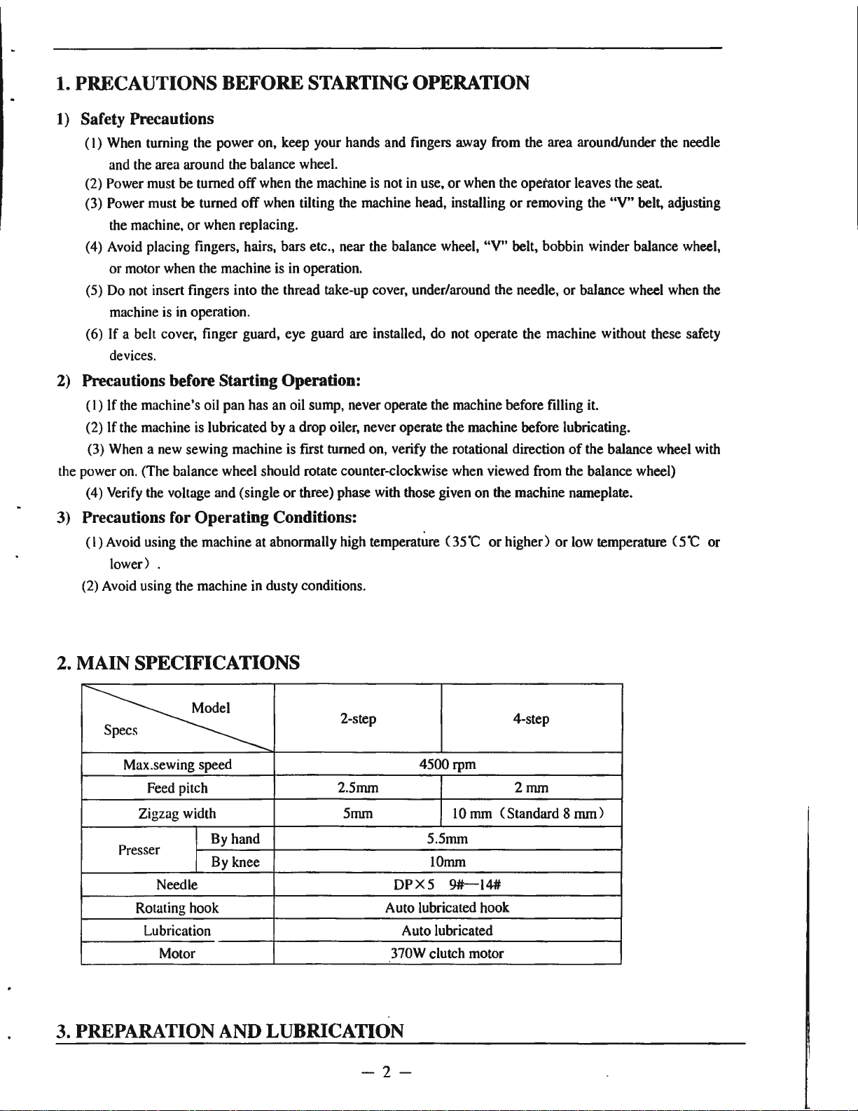
2.
MAIN
SPECIFICATIONS
s
~
Max.sewing speed
Feed pitch
Zigzag width 5mm
By
Presser
Needle
Rotating hook Auto lubricated hook
Lubrication Auto lubricated
Motor 370W clutch motor
hand 5.5mm
By knee 10mm
2-step
2.5mm
4500rpm
DPX5
35"C
or
higher)
10 mm ( Standard 8
9#-14#
or
4-step
2mm
low temperature (
mm)
s·c
or
3.
PREPARATION
AND
LUBRICATION
-2-
Page 4
1)
Cleaning the machine
Before leaving the factory, the machine
parts are coated with rust-preventive grease,
be
which may
dust during storage and shipment. This grease
be
must
2) Examination
strict inspection and test before leaving the
factory, the machine parts may
deformed after long distance transportation with
jolt. A thorough examination must be performed
after cleaning the machine. Turn the balance
wheel
parts collision, uneven resistance or abnormal
noise. If these exist, adjustment must
accordingly before run-in operation.
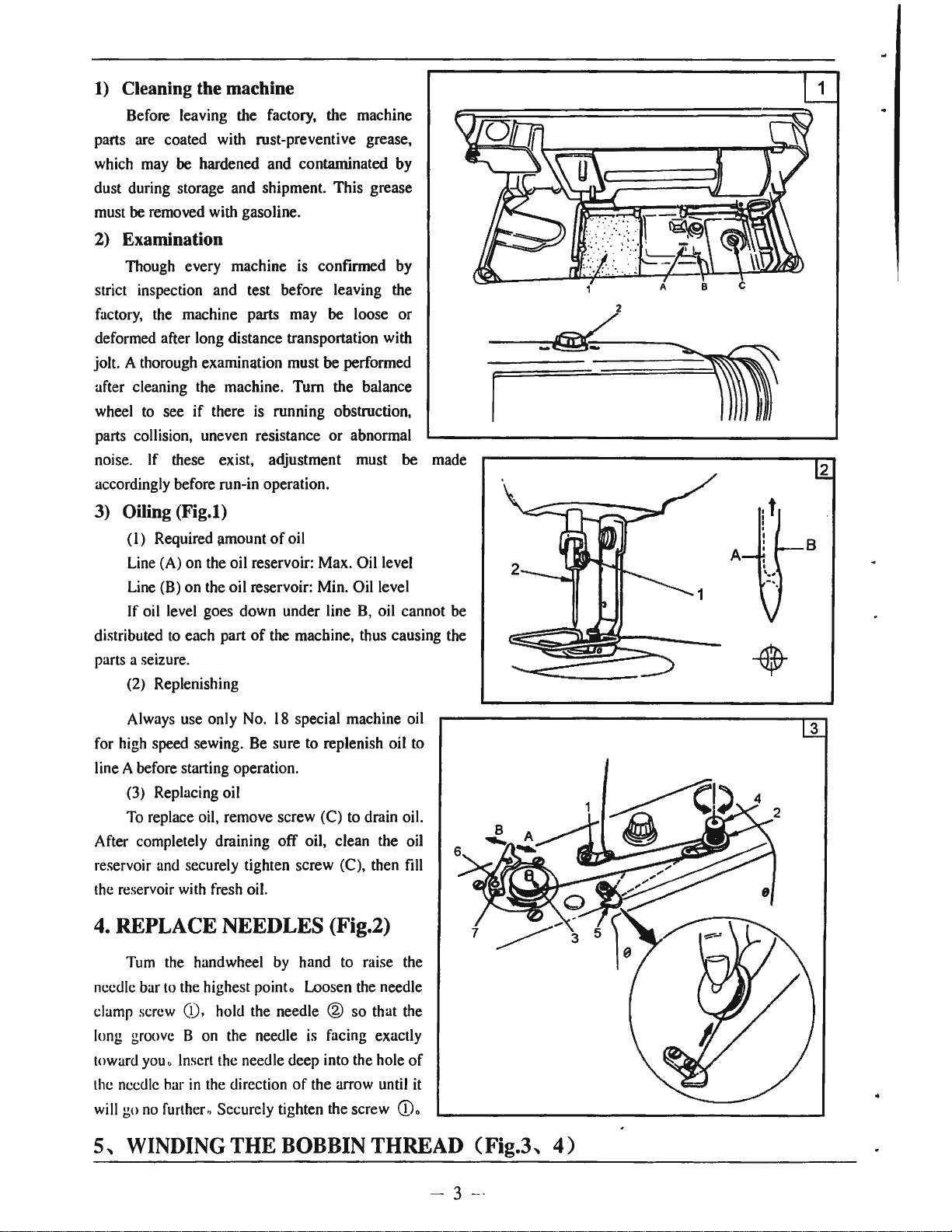
3) Oiling (Fig.I)
removed with gasoline.
Though every machine is confirmed by
to
(I)
Line (A) on the oil reservoir: Max. Oil level
Line (B) on the oil reservoir: Min. Oil level
If oil level goes down under line
distributed
parts a seizure.
(2) Replenishing
hardened and contaminated by
see
if
there is running obstruction,
Required amount
to
each part
of
oil
of
the machine, thus causing the
be
loose or
be
B,
oil cannot be
made
A
,t
I
!
I
I
I
I
I
,.,
2
B
18
Always use only No.
for high speed sewing. Be sure to replenish oil to
line A before starting operation.
(3) Replacing oil
To
replace oil, remove screw (C) to drain oil.
After completely draining off oil, clean the oil
reservoir and securely tighten screw (C), then fill
the reservoir with fresh oil.
4.
REPLACE
Tum the handwheel by hand to raise the
needle bar
damp
long groove B on the needle is facing exactly
toward
the needle har
will go
5,
to
screw (!), hold the needle ® s·o that the
you
" Insert the needle deep into the hole
no
further., Securely tighten the screw (i).
WINDING
NEEDLES
the highest point. Loosen the needle
in
the direction
THE
special machine oil
(Fig.2)
of
the arrow until it
BOBBIN
THREAD
of
. (Fig.3,
3
4)
- 3 -
Page 5
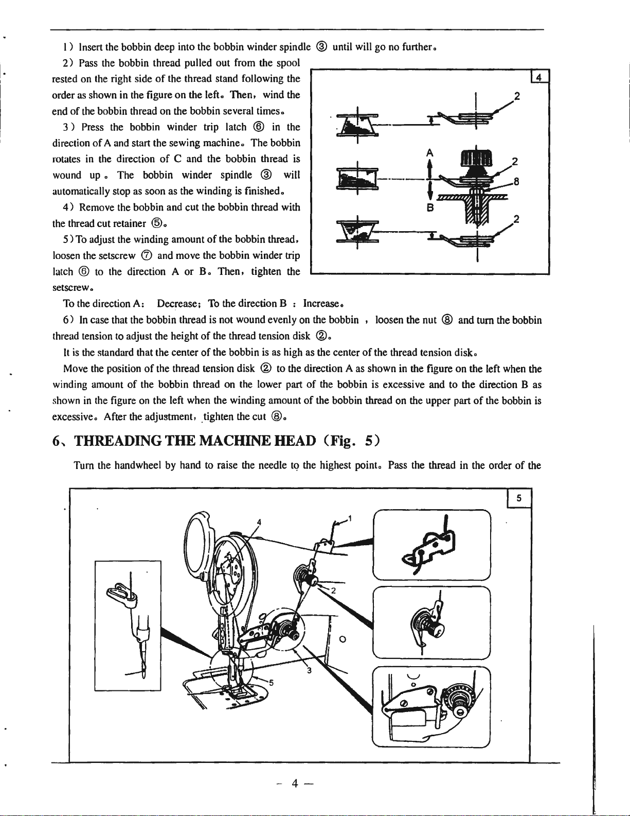
I ) Insert the bobbin deep into the bobbin winder spindle @ until will
2)
Pass the bobbin thread pulled out from the spool
rested on the right side
order as shown in the figure on the left. Then, wind the
end
of
the bobbin thread on the bobbin several times.
3 ) Press the bobbin winder trip latch @ in the
direction
rotates
wound up • The bobbin winder spindle @ will
automatically stop as soon as the winding is finished.
the thread cut retainer
loosen the setscrew
latch @ to the direction A
setscrew.
thread tension to adjust the height
winding amount
shown
excessive. After the adjustment, _tighten the cut
of
A and start the sewing machine. The bobbin
in
the direction
4)
Remove the bobbin and cut the bobbin thread with
5)
To adjust the winding amount
To the direction A: Decrease; To the direction B : Increase.
6)
In
case that the bobbin thread is not wound evenly on the bobbin , loosen the nut ® and turn the bobbin
It
is
the standard that the center
Move the position
in
the figure on the left when the winding amount
of
the thread stand following the
of
C and the bobbin thread
is
®·
of
the bobbin thread,
(J)
and move the bobbin winder trip
or
B.
Then, tighten the
of
the thread tension disk
of
the bobbin is as high as the center
of
the thread tension disk @ to the direction A as shown in the figure on the left when the
of
the bobbin thread on the lower part
®·
of
the bobbin is excessive and to the direction B as
of
the bobbin thread on the upper part
®·
go
no further.
of
the thread tension
disk.
of
the bobbin is
4
6,
THREADING THE MACHINE HEAD (Fig.
Turn the handwheel by hand to raise the needle tq the highest point. Pass the thread in the order
5)
of
the
- 4 -
Page 6
numbers
as
illustrated.
7
..
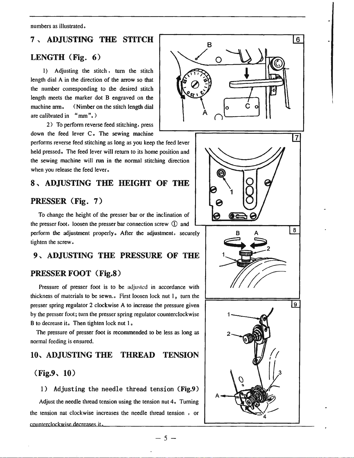
ADJUSTING THE STITCH
"mm".
6)
)
7)
of
the arrow so that
in
the normal stitching direction
OF
THE
LENGTH (Fig.
I) Adjusting the stitch , turn the stitch
in
length dial A
the number corresponding to the desired stitch
length meets the marker dot B engraved on the
machine arm. (Nimber on the stitch length dial
are calibrated
2)
down the feed lever C • The sewing machine
performs reverse feed stitching as long as you keep the feed lever
held pressed. The feed lever will return to its home position and
the sewing machine will run
you
when
the direction
in
To
perform reverse feed stitching, press
release the feed lever.
8.. ADJUSTING THE HEIGHT
PRESSER (Fig.
0
A ("')
0
'-------
6
C o
7
To change the height
the presser foot, loosen the presser bar connection screw
perform the adjustment properly. After the adjustment, securely
tighten
the
screw.
9,
ADJUSTING THE PRESSURE
of
the presser bar or the inclination of
CD
OF
and
THE
PRESSER FOOT (Fig.8)
Pressure of presser foot
thickness of materials to
presser spring regulator 2 clockwise A
by
the presser foot; turn the presser spring regulator counterclockwise
to
decrease
B
The pressure
normal feeding
it.
Then tighten lock nut
of
presser foot is recommended
is
ensured.
is
to be adjusted
be
sewn.. First loosen lock nut l , turn the
to
increase the pressure given
I.
in
accordance with
to
be less as long as
10, ADJUSTING THE THREAD TENSION
(Fig.9,
10)
8
9
1) Adjusting the needle thread tension (Fig.9)
Adjust the needle thread tension using the tension nut
the tension nat clockwise increases the needle thread tension , or
crn,atecclackwise
decreases
iln
4.
Turning
-5-
Page 7
10
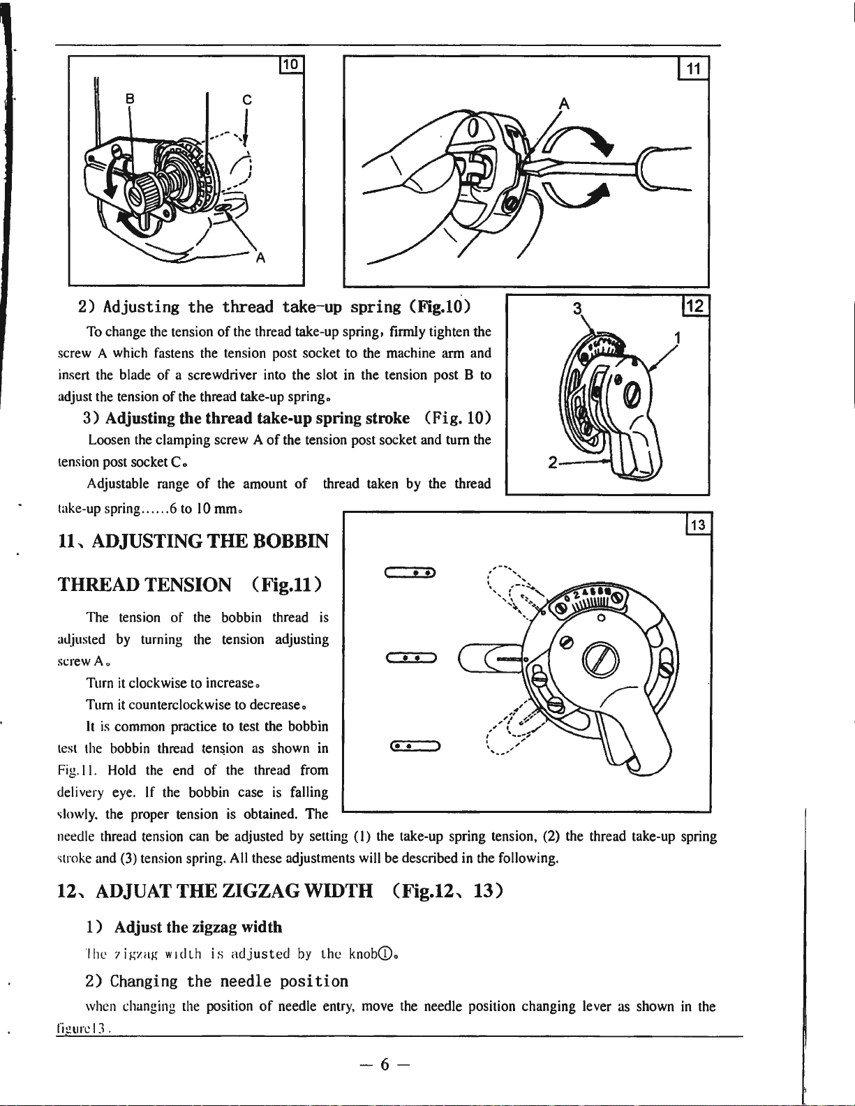
2) Adjusting the thread take-up spring (Fig.IO)
To change the tension
screw A which fastens the tension post socket to the machine arm and
insert the blade
adjust the tension
3)
Adjusting the thread take-up spring stroke (Fig. 10)
Loosen the clamping screw A
tension post socket
Adjustable range
take-up spring
of
a screwdriver into the slot in the tension post B to
of
C.
......
6 to
of
the thread take-up spring, firmly tighten the
the thread take-up
of
of
the amount
IO
mm.
spring.
the tension post socket and
of
thread taken by the thread
tum
the
11, ADJUSTING THE BOBBIN
c •
• •
<•
•>
• >
THREAD TENSION (Fig.11)
The tension
adjusted by turning the tension adjusting
A.
screw
Turn
it
clockwise to increase.
it
Turn
test the bobbin thread
Fig. I I. Hold the end
delivery eye. If the bobbin case is falling
slowly. the proper tension is obtained.
needle thread tension can be adjusted by setting
stroke and
counterclockwise to decrease.
It
is
common practice to test the bobbin
(3) tension spring. All these adjustments will be described in the following.
of
the bobbin thread
ten&ion
of
as shown in
the thread from
is
The
(I)
the take-up spring tension, (2) the thread take-up spring
12
13
12,
ADJUAT
THE ZIGZAG WIDTH (Fig.12,
13)
1 ) Adjust the zigzag width
The
7 i g
:rng width
2)
Changing
when changing the position
l'i!.?.ure
I J"
is
adjusted
the needle
of
by
the
knob(D.
position
needle entry, move the needle position changing lever as shown in the
-6-
Page 8

13, ADJUSTING THE DENSER STITClllNG
(Fig.14)
14
Stitch
This
feature
I ) If you turn the dial with the feed lever held pressed down, the
feed lever will move. Adjust the stitch length for denser stitching
the graduation which meets the top surface
reference:
2)
stitch length. "+2"means "normal feed stitch length is 2mm" and "-2"
means "reverse feed stitch length is
Advert: The graduations on the dial are mere reference. So adjust
the denser stitching while actually observing the finished seam.
length
is
used
Turn the dial
can
in
be
for
the
reduced
fastening
"+"
at
the
star
or
end
of
stitch.
of
the feed lever as
direction to reduce the reverse feed
2mm".
sewing.
talcing
14, ATTACHING I REMOVING THE HOOK
(Fig.15)
When
you
replace the sewing hook, remove it
procedures:
I ) Turn the handwheel until the needle reaches to its highest
position :
2)
Remove the needle, presser foot, throat
plate, feed dog and bobbin case from the machine:
3 ) Remove the setscrew I and take out the
bobbi"n
sewing hook.
the sewing hook. Advert: At this time, make sure
that top end A
is
Never
case positioning finger 2:
4)
Loosen the two screws 4 and remove the
Reverse the above procedures when inserting
of
the bobbin case positioning finger
aligned with line
let
A protrude from line B.
B.
as shown in the figure 15.
in
the following
15
4
16
15,
ADJUST THE POSITION OF
FEED
link
1.2mm.
DOG
To
adjust
I ) Loosen the screw I and turn the feed driving
pin
2 using a screwdriver:
2 ) The standard height
(Fig.16)
the
height
of
the
feed
of
the feed dog
dog
is
t=
--,
-~----~
-7-
Page 9
Inclination
it
so that
16,
center
and feed dog:
throat plate
and adjust so that a height difference
provided between the lowest end
·surface
becomes horizontal when it rises above tha top surface
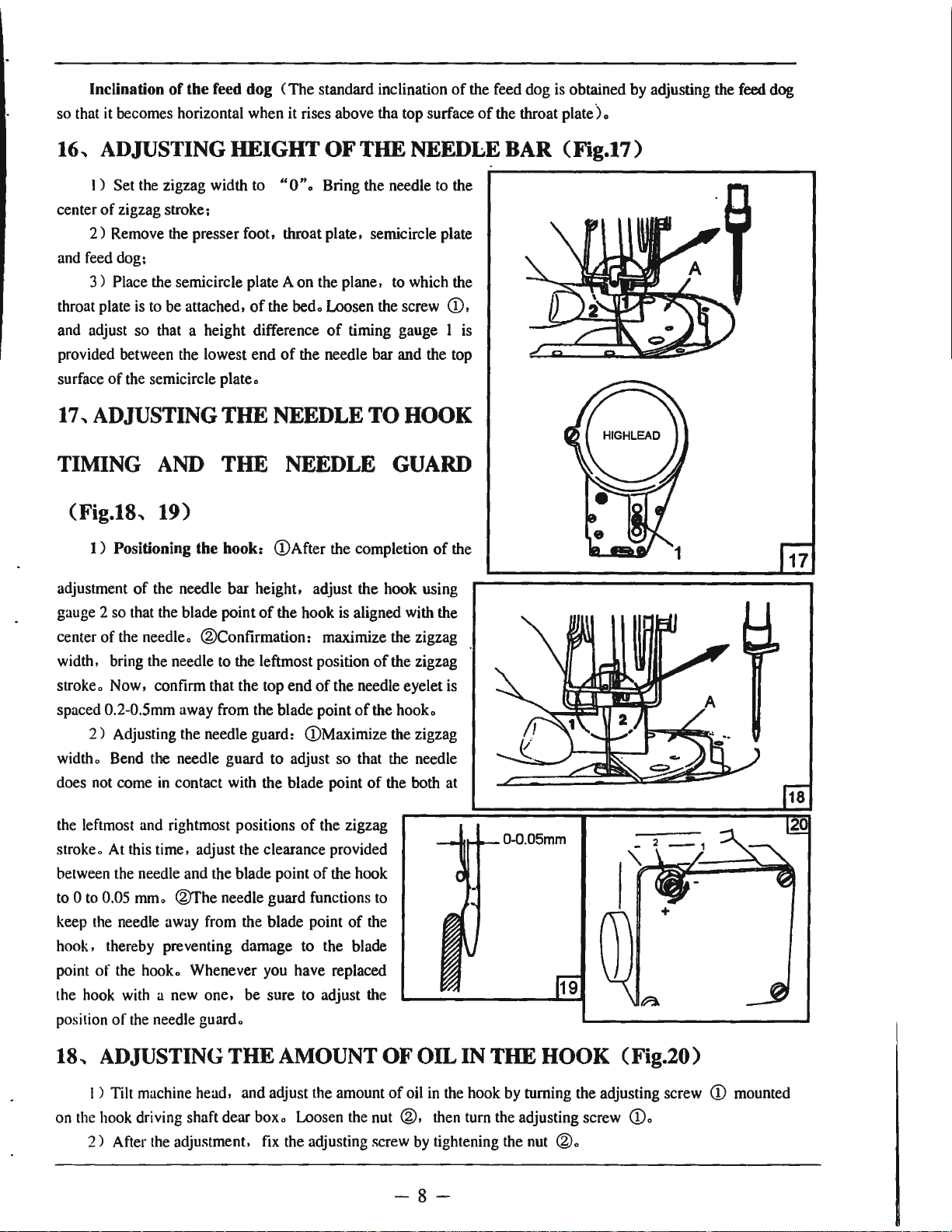
ADJUSTING HEIGHT OF THE NEEDLE BAR (Fig.17)
I)
Set the zigzag width to
of
zigzag stroke;
2)
Remove the presser foot, throat plate, semicircle plate
3)
Place the semicircle plate A on the plane, to which the
of
of
the feed dog
is
to be attached,
the semicircle plate.
of
(The
standard inclination
"O".
Bring the needle to the
the
bed.
Loosen the screw
of
timing gauge l
of
the needle bar and the top
of
the feed dog
of
the throat
CD,
is
17, ADJUSTING THE NEEDLE TO HOOK
TIMING AND THE NEEDLE GUARD
is
obtained by adjusting the feed dog
plate).
(Fig.18,
1 ) Positioning the hook: (!)After the completion
adjustment
gauge 2 so that the blade point
of
center
width, bring the needle to the leftmost position
stroke o Now, confirm that the top end
spaced 0.2-0.5mm away from the blade point
2)
Adjusting the needle guard: (!)Maximize the zigzag
widtho Bend the needle guard to adjust so that the needle
does not come
the leftmost and rightmost positions
strokeo At this time, adjust the clearance provided
between the needle and the blade point
to
Oto 0.05
keep the needle away from the blade point
hook, thereby preventing damage to the blade
point
of
the hook with a new one, be sure to adjust the
position
of
19)
of
of
the needle bar height, adjust the hook using
of
the hook
the needle. ®Confirmation: maximize the zigzag
in
contact with the blade point
mmo
@The needle guard functions
the hooko Whenever you have replaced
the needle guardo
is
aligned with the
of
the needle eyelet
of
of
of
the zigzag
of
the hook
of
the
of
the zigzag
the hooko
the both at
to
is
the
r
+
18,
ADJUSTING THE AMOUNT OF OIL IN THE HOOK (Fig.20)
I ) Tilt machine head, and adjust the amount
on the hook driving shaft dear boxo Loosen the nut
2)
After the adjustment, fix the adjusting screw by tightening the nut
of
oil in the hook by turning the adjusting screw
®,
then tum the adjusting screw (D.
®o
-8-
CD
mounted
Page 10
19, CHANGEOVER OF STANDARD ZIGZAG (Fig.21)
I)
Turn handwheel by hand to bring needle to its lowest position;
2)
Pull changeover lever l toward this side and pull out lock pin 2 from positioning hole 3;
3)
Turn changeover lever 1 while pulling it and adjust it to zigzag mark 4 you desire, At this time ,
securely place lock pin 2 in positioning hole 3 and set it;
4)
When changeover lever l cannot be turned, perform again the work
turning the handwheel by one turn
Caution: Never operate the sewing machine in the state that lock pin 2 is not placed
of
( on the way
changeover). It will cause the trouble
060°
).
Perform repeatedly until changeover work can be completed.
of
the sewing machine a
of
steps
I)
to
in
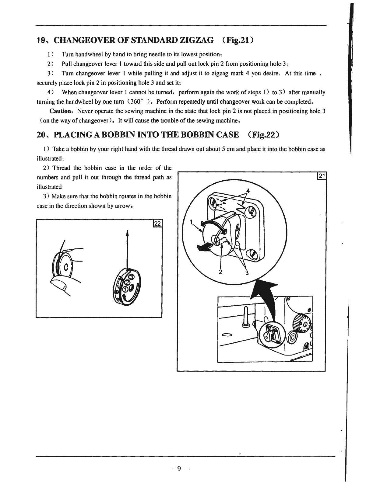
20, PLACING A BOBBIN INTO THE BOBBIN CASE (Fig.22)
3)
after manually
positioning hole 3
1 ) Take a bobbin by your right hand with the thread drawn out about 5 cm and place it into the bobbin case
illustrated:
2)
Thread the bobbin case
it
numbers and pull
illustrated:
3)
Make sure that the bobbin rotates in the bobbin
in
case
the direction shown by arrow.
out through the thread path as
in
the order
of
the
22
as
21
- 9 -
Page 11
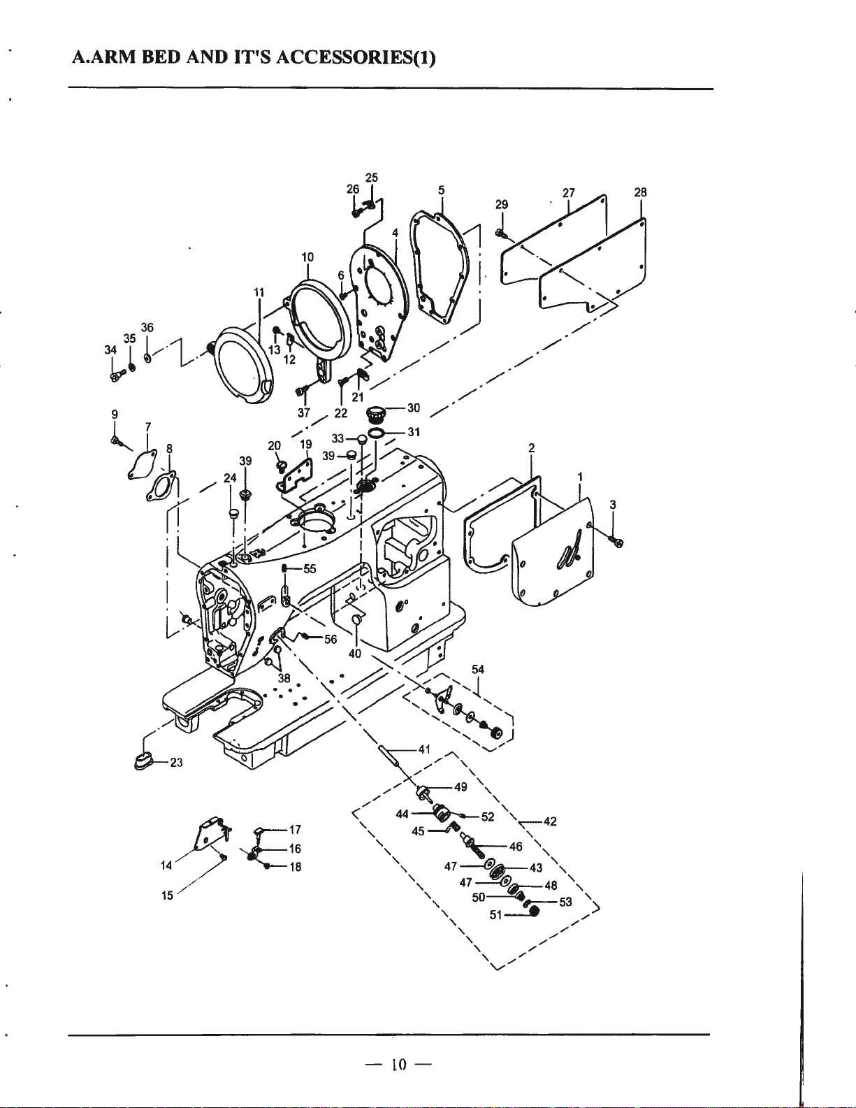
A.ARM BED AND IT'S ACCESSORIES(t)
-
10-
Page 12
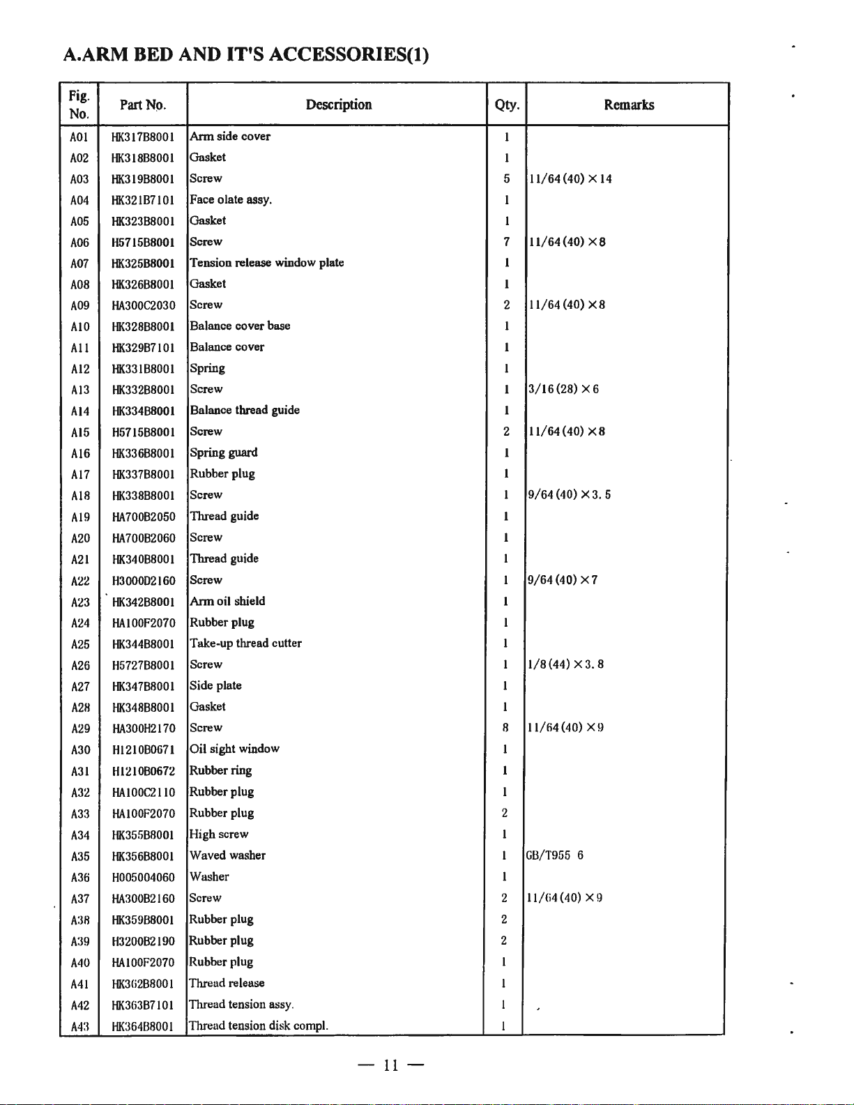
A.ARM BED AND IT'S ACCESSORIES(t)
Fig.
No.
AO!
A02
A03
A04
A05
A06
A07
A08
A09
AIO
All
Al2
Al3
Al4
Al5
Al6
Al7
AIR
Al9
A20
A21
A22
A23
A24
A25
A26
A27
A211
A29
A30
A31
A32
A33
A34
A35
A36
A37
A:!8
A:!9
A40
Ml
A42
A4:l
Part
N9.
HK317B8001
HK.318B8001
HK.319B8001
HK321B7101
HK.323B8001
H5715B8001
HK.325B8001
HK.326B8001
HA300C2030
HK328B8001
HK329B7101
HK331B8001
HK332B8001
HK334B8001
H5715B8001
HK336B8001
HK337B8001
HK338B8001
HA70082050
HA700B2060
HK340B8001
H3000D2160
HK342B8001
HAIOOF2070
HK344B8001
H5727B8001
HK347B8001
HK348B8001
HA300H2170
Hl210B0671
Hl210B0672
HAIOOC2110
HAIOOF2070
HK355B8001
HK356B8001
H005004060
HA300B2160
HK35988001
H3200B2190
HAIOOF2070
HK3G2B8001
HK363B7101
HK36488001
Description
Arm
side cover
Gasket
Screw
Face olate assy.
Gasket
Screw
Tension release window plate
Gasket
Screw
Balance cover base
Balance cover
Spring
Screw
Balance thread guide
Screw
Spring guard
Rubber plug
Screw
Thread guide
Screw I
Thread guide
Screw
Arm
oil shield
Rubber plug
Take-up thread cutter
Screw
Side plate
Gasket
Screw 8
Qty.
Oil sight window
Rubber ring
Rubber plug
Rubber plug
High screw I
Waved washer
Washer
Screw
Rubber plug
Rubber plug 2
Rubber plug
Thread release
Thread tension ass
Thread tension disk compl.
y.
I
I
11/64
5
I
I
7
11/64
I
I
11/64 (40) X 8
2
I
I
I
3/16(28)
I
I
11/64(40)
2
I
I
9/64
I
I
I
9/64
I
I
I
I
1/8
I
I
I
11/64
I
I
I
2
I
GB/T955
I
ll/Ci4 (40) X 9
2
2
I
I
I
I
(40) X
(40) X 8
X6
X8
(40) X 3. 5
(40) X 7
(44) X 3. 8
(40) X 9
6
Remarks
14
-
11
-
Page 13

A.ARM BED AND IT'S ACCESSORIES(t)
Fig.
No.
A44
A45
A46
A47
A48
A49
A50
A51
A52
A53
A54
A55
A56
Part
No.
HK33BB8001
HAI
15B0706
HAI
15B0701
HK368B8001
HA310B0702
HK33CB7101
HAI
15B0703
HAI
15B0702
HA711B0681
HAll5B7010
HK33HB7101
HA100B2110
HA300B2080
Description
Thread
Take-up spring
Screw
Felt
Tension disc holder
Tension release pin assy.
Tension spring
Tension nut
Screw
Rotating stopper
Pre-tension controller assy.
Screw
Screw
tension
rod assy.
Qty.
1
I
I
2
I
I
1
1
1
I
1
1
1
9/64
15/64
(40) X
(28)
Remarks
4.
5
X6.
5
-
12
-
Page 14

B.ARM BED
AND
IT'S
ACCESSORIES(2)
-
13
-
Page 15

B.ARM BED AND IT'S ACCESSORIES(2)
Fig.
No.
BO!
B02
B03
B04
B05
B06
B07
BOB
B09
BIO
Bil
Bl2 H200000360
Bl3
Bl4
Bl5
B16
Bl7
BIS
Bl9
820
B21
822
823
B24
825
826
827
828
82~)
B30
B:Jl
8:J2
8:
8:!4
IHfi
B:
l{:17
B:l8
IH!l
IWl
B,J I
Bl2
B•I
HK374B8001
HA300B2160
HK376B7101
HK377B8001
HK37BB8001
HK380B8001
HAI00B2060
HK383B8001
HK384B7101
HK388B8001
HK38988001
HA300B2190
HK359B8001
HK391B7101
HA30082160
HK395B8001
HK397B8001
HK398B7101
HK399B7101
HK30BB7101
HK30EB8001
HK30FB8001
HK33AB8001
H6720N8001
HAI00H2150
H6721N8001
H3200B2100
Hfi722N8001
H7214J8001
H733ID8001
H6717N8001
l3
H6724N8001
H0070!3050
H4:II050050
114:l
l!i
HK:l l GB800
I-IK31HB8001
Hfi312D8001
HJ(:! I JB800
HK:!
IICi7iifiB8001
1-1Ci7
:l
Part
No.
I 030040
I JB800 I
Ci2B800
Description Qty.
Support plate
Screw
Helical gear box cover assy.
Helical
gear
box
cover
Bed screw stud
Connecting screw
Screw
Bed plate
Bed slide assy.
Oil shield plate
Oil shield rubber
Screw
Screw 4
Rubber plug 1
Helical bevel gear box cover assy.
Screw 3
Nylon cap 1
Needle plate 1
Bobbin device assy. I
Bobbin fitting basis assy. 1
Bobbin brace assy. 1
Bobbin shaft 1
Bobbin cam shaft I
Bobbin cam
Bobbin lever
Screw 1
Adjust plate 1
Scrw
Washer
Bobbin winder wheel
Rubber ring 1
.
Cushion I
Spring
E-ring
Screw
Screw 2
Gasket 1
J..
Bobbin winder wheel
Screw
Tirrentl guide 1
I
Screw 1
Tirread cutter 1
Screw 2
I
I
2
1
1
2
1
4
1
1
1
1
2
I
I
1
1
2
1
I
2
1
I
2
11/64(40)
11/64
(40)
11/64
(40)
11/64
(40)
(40)
11/64
M5X5
M3X4
1/4
(40)
11/64
(40)
Remarks
XI0
X 9
X5
X4. 5
X9
X6
X5
-14-
Page 16

B.ARM BED AND IT'S ACCESSORIES(?)
Fig.
No
844
845
B46
847
B48
849
850
851
Part No.
.
HK32AB7101
HA71080671
HK33IB8001
HA11280693
H420680661
HK31188001
H5729F8001
H3107G0662
Description
Bobbin thread tension assy.
Bobbin thread nut
Bobbin thread soring 1
Bobbin winder thread disc
Bobbin thread screw 1
Thread guide 1
Nut 1
Screw 3
Qty.
2
Remarks
1
1
11/64 (40)
-
15
-
Page 17

C. UP SHAFT MECHANISM
- 16 _ .
Page 18

C.UP SHAFT MECHANISM
Fig.
No.
COi
CO2
C03
C04
cos
C06
C07
COB
C09
CI0
Cl!
Cl2
C13
C14
Ci5
Ci6
Cl7
ClB
C
C20
C21
C22
C23
C24
C25
C26
C27
C28
C29
C30
C3I
C32
C:
C34
C
35
C36
C37 HK341C8001
C38
C39
C:
40
(4
C42
C43
i9
13
1
Part
No.
HK305CB00I
HK307C8001
HAI
11
IE204
028018
HK309C7101
HK310CB00I
H3205J0662
HA307C0662
HK312C8001
HA306D0066
HK314C8001
HA307C0662
HK316C8001
H2405D0664
HK317C8001
HK318CII001
HK320C8001
HK322CII001
HK323C8001
HK325C7101
HK329C8001
HK330C7101
HAI00C2020
-HAI00C2020
HA100C2070
HA705C0662
HA307C0662
H4100B2180
HA105D0066
HK333C7101
HA104C0655
HK
336C
8001
HK337CII00I
HK338CII00I
HK339C8001
HK340C8001
HAI00C2170
H3211
ID604
HA300B2160
HA300C2030
HK343C7101
HK344C8001
Description Qty. Remarks
Up
shaft I
Oil adjust pin
Oil wick
Rubber ring
lbrust
collar assy.
Pushing I
Bearing
Screw
Oil seal coller
Oil seal I
Sprocket (up) I
Screw
Hand wheel
Screw 2
Balance l
Up
shaft
bushing(left)
Up
shaft
bushing(middle)
Counterweight l
Counterweight plate l
Take-up counterweight assy.
Timing belt
Needle bar crank
Screw l
Screw I
Screw
Rubber ring
Screw 2
Screw 3
lbrust
collar assy. l
Needle bar crank assy. l
Bearing
Needle bar connection
Thread rack
Needle b
Needle bar connection
Needle bar connection
Needle
Screw I
Screw
Screw
Screw 2
Needle bar yoke assy.
Needle bar yoke l
ar
guid
e l
guide
2 I
I
I
I
I
I
6204ZNR
1/4(40)
2
I
l/4(40)X6
2
I
15/64
l
l
l
l
I
15/64
15/64
l
l
9/64
l
l
l
l
l
DPX5 10#
l
1/8
9/64
l
I 1/64 (40) X
2
l 1/64 (40) X 8
l
X6
(211) X 14
(28)
(28)
(40) X
(44) X
4.
(40) X 8. 5
8.
5
10
X
X
10
10
6
-
17
-
Page 19

C.UP SHAFT MECHANISM
Fig.
No
C44
C45
C46
C47
C48
C49
C50
C51
C52
C53
C54
C56
C57
Part
.
HK345C8001
HK346C8001
HK347C8001
HK349C8001
HK350C8001
HK352C8001
HC04050019
HK354C8001
HK355C8001
HA100B2110
HK358C8001
HD409H8001
No.
40200
Description
Shaft
Shaft bushing (up)
Shaft bushing (down)
Spring pin
Shaft bushing (left)
Guide pin
Screw
O-ring
Needle bar yoke presser
Shaft bushing (ringht)
Screw
Screw
Bearing
Qty.
I
I
I
1
I
I
I
1
I
1
1 11/64 (40) X
9/32 (28) X
1
1
Remarks
5.
5
6.
3
18
Page 20

D.NEEDLE VIBRATOR & ADJUSTMENT COMPONENTS(l)
49
~
{}-24
~
20
~55
-
19
-
Page 21

D.NEEDLE VIBRATOR & ADJUSTMENT COMPONENTS(t)
Fig
No
DOI
002
D03
D04
005
006
D07
008
009
D10
011
D12
01:1
D14
D15
DJG
017
DIil
Ol!l
D20
1)21
1)22
02
:1
D24
()2!i
1)2(;
027
()211
02!1
n:
10
IJ:11
D:l2
0:
1:1
IJ:14
l):l!i
IJ:Hi
1):17
IJ:lll
11:1!)
()'(()
D•I I
ll-1:l
II
1:1
.
Part
.
HK304D7101
HK305D8001
HK306D8001
HK307D7101
HK308D8001
HA104G0012
HK31
HK312D8001
HK313D7101
H3207F0672
HA7311CC06
HK317D8001
HK318D8001
H421l050040
HK320D8001
HK322D8001
HK324D8001
H428050060
H3210F0682
HK32fiDll001
H421l050040
HK328Dll001
HAIOOF2070
11007009100
HK332D7101
HK:133D1100
H0070
1-10070 l :lOfiO
HC
HK3:HD8001
HJ<:l38Dll001
HK3
HIC140Dll001
HK34!Dll001
1-12,io
HK:M
HK:
HE!l2!)1)1l00
I
UtM!JDllOO
I IK:1 I
I
lK:!:lCDllOO
l
lK:15201100
lK:1:i:IDllOO
I
No.
ID8001
J :!040
0404001!>
:l!
>D710
,1 r 003,i
:lDllOO
l4
IDllOOJ
!IBllOO
Drive link assy.
Drive link
Shall
Shall connection assy.
Shall connection
Screw
Link 1
Pin 1
Collar 1
Screw
Screw
Pin 1
Needle driving rod
Screw
Shall
Needle cam
Needle driving
Screw
Screw
Shall 1
Screw
Bushing 2
Plug 1
C-ring
Change over basis assy. 1
Roller I
I
E-ring 4 2
E-ring 5
Rubber ring I
Spring
Change over slide shall l
Change over lever assy. I
I
Change over lever
Pin
Screw
Change over basis
I
Gasket I
Screw 4
I
Needle cam
1
Screw
I
Rubber plug
I
Needle cam shall
I
Needle cam roller
I
ann
Description Qty.
ann
I
1
1
1
1
3/16(28) X 12
1
70. 1
8. 5
X6. 5
M5 X 14
11/64 (40) X
2
9/64(40)
2
1
M5X4
2
1
1
1
M5X6
2
GB/T
1
M5X4
4
'
1
2
·I
l
l
9/64
I
1
1
3 l
l
2
2
(40) X 8. 5
I/64
(40) X
14
Remarks
-
20-
Page 22

D.NEEDLE VIBRATOR & ADJUSTMENT COMPONENTS(t)
Fig
.
Part
No
044
045
046
047
048
049
050
051
052
053
054
055
056
057
058
059
060
061
062
.
HK35508001
HK35608001
HAIOOC2190
HA307C0662
HK35908001
HK36008001
..
HK36108001
HK36208001
HK36408001
HK36508001
HK36608001
H4707I8001
HC04070019
HK36907101
HK371D7101
HA34110308
HA10500662
HA108C0663
H007009100
No.
Worm
wheel
shaft
Worm
wheel
Screw
Screw
Worm
Rubber plug
Camshaft
Bushing
Drive link guide 1
Pin
Drive link guide 2
Screw
O-ring
Thrust collar assy.(back)
Thrust collar assy.(front)
Screw
Screw l
Screw l
Snap spring 1
Description Qty.
1
1
3 11/64
4
1
1
1
1
1
1
l
1
1
l
1
1
(40) X 10
1/4(40) X6
1/4(40) X6. 5
(28)
15/64
1/4(40) X4
l/4(40)X7
X 7
Remarks
-
21
-
Page 23

E.NEEDLE VIBRATOR & ADJUSTMENT COMPONENTS(2)
0
0
rhr-
..
-5fi-
~
(~J~,,,,,......
\ 46 I
\ I
\
___
-
22-
/
ll-··
------
............
...,
45
__
J
·
41
47
r·
"l
'
.-J
51
"f@
24
Page 24

E.NEEDLE VIDRA T
OR
& ADJUSTMENT COMPONENTS(2)
Fig.
No.
EOI
E02
E03
E04
E05
E06
E07
E08
E09
EIO
Ell
E12
El3
El4
El5
El6
El7
EIS
El9
E20
E21
E22
E23
E24
E25
E26
E27
E28
E29
E30
E31
E32
E33
E34
E35
E36
E37
E38
E39
E40
E41
E42
E43
Part
No.
HK373D7101
HK374D7101
HK377D8001
HK378D8001
HK385D7101
HK386D8001
H42'('040050
HK388D7101
HK389D8001
HK390D8001
H3406C8001
HK39ID8001
HK392D8001
HK393D7101
HK394D8001
HK395D8001
HK396D8001
HA104J6510
HK398D8001
HK399D8001
HK30AD8001
HA104C0659
HK30CD8001
HK30DD8001
H007009100
HK30FD8001
HA104J6510
HK30HD7101
H007013020
HK318D8001
HK31CD8001
HK31DD7101
H007013040
HE01040
HK31HD8001
HK31ID8001
HK31JD8001
HK32AD8001
HK328D8001
HK32CD8001
HK32ED8001
HK391D8001
H32481BC21
Description
Scale plate assy.
Scale mounting base assy.
Scale plate 1
Screw 2
Adjusting pick-up assy.
Adjusting pick-up
Screw 2
Lever assy. 1
Lever 1
Screw
Washer 2
Nut 2
Knob 1
Base assy.
Needle position adjusting base 1
Highe screw 1
Waved washer 1
Nut
Base mounting plate 1
Arm
Shaft 1
Screw
Washer
Waved washer
Snap ring
Shaft 2
Nut
Stopper assy. 1
E-ring
Nut 1
Nut stopper
Lever assy. 1
E-ring
Hand
stop
crank
shaft
ball
ct>
4
Spring
Oil shield
Screw
Packing
Roller
Adjusting pick-up screw
Knob
Nut
Screw
Qty.
2
2
1
1
(44)
1/8
1
1
M4X5
9/64
2
(40)
3.
7X7.5X0.8
1
12.
8. 5X
15/64
1
I
1
9/64(40) X6
3
3
10.
2X
3
10.5Xl4.5X0.3
1
1
15/64(28)
1
1
1
1
1
I
I
9/64(40)
1
1
1
1
I
9/64
(40)
X 2. 5
(28)
18XO
X 3. 5
5XO.
. 5
X5
X (i
Remarks
3
-
23
-
Page 25

E.NEEDLE VIBRATOR & ADJUSTMENT COMPONENTS(2)
Fig.
No.
E44
E45
E46
E47
E4H
E49
E50
E51
E52
Part
No.
H3406C8001
HK32FD7101
HK32GD8001
HK32HD8001
HK32IDB00I
HA30082160
H2404I0034
HK338D8001
H7353G8001
Washer
Lever
assy.
Lever
Key
Spring
Screw
Screw
Screw
Washer 1
Description
Qty.
2
1
1
1
1
4
1
1
1
11/64
9/64
3/16
10.
2X 18X 1
Remarks
(40) X 10
(40)
X8. 5
(32)
X6. 5
- 24 -
Page 26

F.PRESSER FOOT MECHANISM
20
,-L-1
:
21-i
I I
I I
I
122~
l:_
_____
23
J
l
27
I
26
24
0 /
<
t}--14
33
25
16
~
[__..
~
-0---L
____-- I I
I O I
I I
I I
I I
I I
I I
I I
I I
I
______
__
_ I
I
I
I
I
I
I
I
L
_____
30
J
-
25
-
Page 27

F.PRESSER FOOT MECHANISM
Fig.
No.
FOi
F02
F03
F04
F05
F0!i
F07
FOB
F09
FI0
Fil
Fl2
Fl3
Fl4
Fl5
Fl6
Fl7
FIR
Fl!l
F20
F2l
F22
F23
F24
F2fi
F26
F27
F2R
F2!l
r:10
F31
F:12
F:l:l
F:M
r:1ri
F:lli
P.art
No.
HK304E7101
HK312E7101
HK313E8001
HA300H2080
HK316E8001
HK317E8001
HK318E8001
HK319E8001
HK320E8001
HK32IE7101
HK322E8001
HK323E8001
HK324E8001
HK325E8001
HA107H0662
H3200E2010
HK328E7101
HK329E8001
HAI l 1G0683
H5404F7101
H5405F8001
H5406F8001
HAIO0H2120
IID511Q8001
HK335E8001
HN705FR001
HA:3008217
HK339E8001
HK340E8001
HK342E8001
HK343E800l
H3200E2020
li4!ll 4
H0070130!i0
HK346Ell001
HA305E0662
0
IH00
Description Qty.
Presser foot assy.
Hand lifter cam comp!.
Hand lifter cam
O-ring
Lifting lever
Screw
Lifting lever link (left)
Screw
Lifting lever connecting rod
Litling lever link (right) assy.
Lifting lever link (right)
Screw
Spring
Swivel
Hinge screw
Presser bar
Presser bar guide bracket assy.
Presser bar guide bracket
Screw
Presser spring regulator assy.
Presser spring regulator
Nut
Presser guide bar
Spring
Bushing
Hand lefter
Screw
Lifting lever gasket
Hinge screw
Connecting rod, vertical
Screw
Screw
Nut 1
1
Snap ring 2
Screw
Screw
1
1
1
1
1
1
1
2
1
1
1
l
1
1
1
l
1
1
11/64
1
1
1
1
1
1
1
1
11/64
1
1
1
1
3/
16
1
1
1
1
(32)
1/8
(44)
3/16
(28)
15/64(28)
15/64 (28) X 4. 5
Remarks
(40) X 12
(40) X 10
-
26
-
Page 28

G.STITCH
LENGTH
REGULATOR MECHANISM
24
l 23
19
'~
27
-
27
-
Page 29

G.STITCH LENGTH REGULATOR MECHANISM
Fig.
No.
GOl
G02
G03
G04
G05
G06
G07
GOH
G09
GIO
GI
Gl2
Gl3
Gl4
Gl5
G
(;(7
GIB
Gl9
G20
G21
G2:l
G2'.l
G:l4
1:2
G:l!i
HK305F8001
HK338D8001
HK306F8001
HK307F7101
HK309F7101
HA104G0012
HK312F8001
HK313F7101
HK314F8001
H6039G8001
HK315F8001
I
HK331F8001
HK319F8001
HK316F8001
HA300C2030
ICi
HK317F8001
HK318F8001
HK30DD8001
HK320F8001
HK321F8001
HK322F8001
HA109F0674
HAIOOF2080
HAIOOF2090
r,
HK326F8001
HK327F8001
Part No.
G27 H4!Jl418001
G28
HK329F8001
(;'.,!!)
HK330P8001
G:IO
HK33:lF8001
c;:31
HK333F8001
c::1:l
HK:l:l4F800
c:3:1
HK335F8001
c;:34
HK3:l6F8001
G:15
HK338F8001
i;
:w
I
c::l7
IA I 04GOO
HK:l40F7
l:l
IO
Description
Lever
Screw
Shaft
Thrust
colter assy.
Condense stopper
Screw
Feed driving
Knobassy.
Knob
Screw
Adjusting screw
Screw
Adjusting screw
Stopper
Screw
Adusting bushing
Stopper dial plate
Waved
washer 1
Feed dial
Screw
Adjusting screw
O-ring 1
Pin
Spring
Link
Screw 2
Nut
Pin
Scale plate
Spring
suspension I 1
Torsion
Spring suspension 2
I
Slipper 1
Screw
Feed variable arm
Screw
Bushing assy.
I
spring
arm
adjuster
base
assy.
Qty.
1
3/16(32) X6. 5
1
1
1
1
3/16(28) X 12
2
1
1
1
11/64 (40) X 3. 5
1
I
4 3/16(28) X6
1
1
11/64
1
(40) X 8
1
I
10.5Xl4.5X0.3
1
1 3/16(28) X
1
GB1235
14X2. 4
1
1
1
I
1
1
1
1
1
1
3/16(28) X
I
1
Remarks
18
12
-
28-
Page 30

H.
FEED
MECHANISM COMPONENTS
28
1
17
43~
40
44~
8
-
29
-
Page 31

ff.FEED MECHANISM COMPONENTS
Fig.
No
HO!
H02
H03
H04
HOS
H06
H07
HOR
HO!l
HIO
HI!
H
1-113
Hl4
Hlfi
HlCi
1-117
HI
H19
H20
1121
1122
112:1
H21I
112fi
112(i
11
H2H
112!)
11:!0
11:11
ll:l2
11:1:1
11:14
11:l
ll:lli
11:17 HK:1:l4G
11:!/l
11:1!1
IMO I IK:1:lHGHOO
1
14
IM
II
.
12
H
27
!i
1
2
1:1
Part No.
HK305G8001
HK306G8001
H491418001
HK307G8001
HAIOOE2150
H720918001
HK310G8001
HA305E0662
HK31
IG800l
HK312G8001
HK3l3G7101
HE929D800l
HK316G8001
H3221
IG205
HK3l7G8001
HK3l8G8001
HK319G8001
HK320G8001
HK321G8001
HA104GOOl2
H007013035
HK322G7101
HK:123G800
HA:I07C0662
I
IA I 08C06Ci3
HEIO(iF8001
HK:124G800
H20l0JOOfili
HK:12fiGROOI
HK321iG800
I-IK3
27G
ROO
HA
:l4 I ID:l08
HK330GHOOI
HK331G8001
HK:1:12G800I
Hltl:l:IGHOO
HOO
IIK
:l:HiG
HOO
l11\:l04G0Cifili
IIK
:1:l!
lGHOO
IIA700F2l00
HK:1-IOGHOO
Description
Feed reversal link
Hinge screw
Nut 2
Tension spring back
Screw l
Spring
Feed base l
Screw
Felt
Link
Balance weight comp!. l
Screw
Feed dog
Screw
Shatl
Feed rocker
Spacer
Link shaft
Screw 2
Screw
E-ring
Collar assy. 1
Collar
I
Screw 2
Screw
Screw 2
Screw 2
I
Nut
Shall
Bushing (letl) l
I
Bushing (right)
I
Screw
Eccentric
Rod
Side disc plate l
Bearing
I
Connecting rod
I
Feed rocker shatl crmtk
I
Screw
Fe
I
Plate (!ell)
I
Screw 4
Stopp
I
cam
ed
driving rocker 1
er
plate
Qty.
l
2
3/
l
11/64
l
15/64
l
l
l
11/64
2
l
2
l
1
2
l
3/16(28)X9
4
3/16(28) X 14
3. 5
1
l
1/4(40)
2
9/32
2
l
I
15/64
l
l
l
K22X26X
l
l
l
3/16(
l
l
11/64
l
16
(28)
(40) X 10
(28) X 4. 5
(40) X 7. 5
1/8
(40) X
l/4(40)X7
X8
l/8(44)X6
(28)
(28) X 7
28) X 15.
(40) X 8. 5
Remarks
6.
3
. 4
10
(NTN)
-
:30
-
Page 32

ff.FEED
MECHANISM
COMPONENTS
Fig.
No.
H44
H45
H46
H47
H48
H49
H50
H51
H52
Part
No
.
H2400l2080
HK342G8001
HK343G8001
HK344G8001
HK346G8001
HK347G8001
HK348G8001
HK349G8001
HA100E2150
Description
Screw
Plate (right)
Shaft
Bushing
Feed variable
Feed driving rocker block
Pin
Reverse feed limiter
Screw l
ann
Qty.
11/64(40) X7
1
l
1
l
1
2
l
1
11/64
Remarks
(40) X 11
-
31
-
Page 33

I.LOWER
SHAFf
MECHANISM
12--{i
~~
_ft ..
-<l/
17
18
--~
~~
-
32
-
Page 34

I.LOWER SHAFT MECHANISM
Fig.
No.
IOI
I02
I03
I04
I05
I06
I07
I08
I09
110
Ill
112
113
114
115
116
117
118
119
120
121
122
123
124
125
126
127
128
129
130
131
Part
No.
HK304H7101
HK308H8001
HK309H8001
HK310H8001
HA3411D308
HK312H8001
HK313H8001
..
HE106F8001
HK314H8001
HA300C2030
i-lA34 l lD308
HAI08C0663
HK315H8001
HA104E0011
HAll
llEI04
HAll
llE204
HK319H8001
HK320H8001
HK321H8001
HK322H8001
HK324H8001
HK325H8001
HK326H8001
HK327H8001
HK328H8001
HK329H7101
HK331H8001
HK333H8001
HK334H7101
HK335H8001
HA307C0662
Description Qty. Remarks
Hook comp!.
Hook shaft
Hook shaft bushing
Hook shaft bushing
Screw
Bushing cap
Gasket
Screw
Inner hook stopper
Screw
Screw
Screw
Bearing
Oil seal screw assy.
Oil seal screw
Oil wick
Gear
Gear
Bobbin case assy.
Bobbin
Bushing l
Helical gear
..
Helical gear
Bushing l
Shaft l
Hook driving shaft l
Bushing l
Bushing
Sprocket assy.
Sprocket
Screw
DP2-57(3LP2R)
l
l
l
l
15/64
l
l
l
1/8(44) X6
2
l
11/64
l
15/64
4
1/4(40) X8
8
l
9.
525 X 22.
l
l
l
l
l
225-24169
l
225-96704
l
l
l
l
l
I
1/4(40)
2
(28)
(40)
(28)
X 7
X 9
X 7
225
X7
-
33
-
Page 35

J.OIL LUBRICATION MECHANISM
50
~51
~
, I
) :
·4
1
-
34
-
Page 36

J.OIL LUBRICATION MECHANISM
Fig.
No.
JOI
J02
J03
J04
J05
J06
J07
JOB
J09
JlO
Jll
Jl2
J13
J14
J15
J16
Jl7
Jl8
Jl9
J20
J21
·
J22
J23
J24
J26
J27
J28
J29
J30
J31
J32
J33
J34
J35
J36
J37
J38
J39
J40
J41
J42
J43
J44
Part
No.
HK304l7101
HK30918001
HK31018001
H3000D2030
HK31118001
HK313l8001
HA300C2030
HK314l7101
HK315l8001
HK316l8001
HK31718001
HK319B8001
HK380B8001
HK319l8001
HK320l8001
H200000360
HK32118001
HA3411D308
HK32218001
HK323l8001
HK32418001
HA105D0662
HK325l7101
HK32618001
HK32918001
HA104J6510
HK33018001
HK33118001
HK33218001
HK33418001
HK335l8001
HC04060019
HA100E2150
HK340l7101
HK34218001
HK343l8001
HA700M0070
HK35318001
!{1{35417101
HK355l8001
HK35618001
HK31918002
HK319l8003
Description Qty. Remarks
Oil supplypipe assy.
Oil supplypipe
Distributor
Screw 1
Connecting screw
Felt presser
Screw
Oil tank assy.
Gasket
Oil tank
Oil tube
Screw
Connecting screw
Oil tube
Oil felt guide
Screw 1
Bushing
Screw 1
Shaft 1
Pump
driving gear
Pump
driving gear
$crew 4
Thrust collar assy. 1
Thrust collar
Screw
Nut
Plunger thrust plate
Spring
Plunger
Screw
Spring
0-ring
Screw
Lubricating oil pump assy.
Rubber joint
Rubber joint l
Cable band
Oil wick
Oil regulating valve assy. 1
Oil regulating valve l
Wiper link joint 1
Oil tube
Oil tube
l
1
1
3
1
2
1
1
1
1
2
1
1
1
1
1
1
1
1
1
1
1
1
1
1
1
2
l
1
I
l
l
l
11/64
(40) X 4.
11/64
(40)
11/64
(40) X 14
11/64(40)
15/64
(28)
1/4(40)
X4
•
5
X 8
.
X7
X 7
•
-
35
-
Page 37

J.OIL LUBRICATION MECHANISM
..
Fig.
No.
J45
J46
J47
J48
J49
J50
J51
J52
Part
No.
HK35918001
H5729F8001
H3406C8001
HK319B8001
HA300C2030
H5733F8001
HK364l8001
HK365l7101
Description Qty. ·
Oil adjusting screw
Nut
Washer
Screw
Screw
Screw
Oil shield
Felt assy. l
l
11/64 (40)
l
2
11/64 (40) X
l
11/64(40) XB
I
11/64 (40) X 8
l
l
Remarks
14
•
•
- 36 -
Page 38

K.ACCESSORIES
r------------7
•
1
I
22
23
21
:o.q
! -.. ,
I
I
L--------~~
,,,,,,
/
(
I
l..
'
'
45
°'
.
~
24
/
/
/./
///
......
......
26
1
I • u I ,
I
r !
25
..._J,,,,
~:;,,,
~
/
' /
,,,,
30
20 ~;----~~----L
,,,,,,,/
/
1
32
'-.._
33
V
____
_
\ij\
?
47
36...-a,
35--fil
34
~
~
~
28
27
~::
~:
/-41
- 37 -
Page 39

K.ACCESSORIES
•
Fig
.
No.
KOi
K02
K03
K05
K06
K07
KOH
K09
KIO
Kil
Kl2
Kl3
Kl4
Kl5
Klfi
Kl7
Kl8
Kl!)
K20
K21
K22
K2
:l
K24
K2!i
K2!i
K27
K28
K2!1
!O
K:
K:
ll
K:12
K:l
:l
K:l4
K:
l!i
:w
K
K:l7
:l
l!
K
K:l!l
K40
K-
11
1
12
K
1
K
1:1 HA:
K11,1
Part
No
.
HK304J7101
HA104J0655
HK306J8001
HA104J0658
HA106J0663
HA300J2160
HK308J8001
HK309J8001
HA104J0653
HA104J0652
HA104J6510
HA104J0659
HA110D0672
HA300J2180
H007013090
HK310J8001
HAI06J0661
HA100J2120
HAI06J0066
HA106J0665
HA106J0668
HA106J0662
IIAI
06J0666
HAI06J0667
HA200J2030
HK341C8001
HK322H8001
HK:ll4J8001
HA313.l7101
HA30082l!i0
Hl!O(i045250
50
HAI
!OJ0070
HAIOOJ2090
HAIOOJ2100
HBOI020
HB01030
liA300J2070
HA300J2200
HA300J2210
HD!iO(iS800
I
I05EOCi(i2
IIA:IOOJ:l
170
Description
Oil reservoir assy.
Oil reservoir gasket
Oil reservoir gasket
Connecting rot.
Bracket
Knee press rod
Spring
Rubber pluge
Rubber ring
Screw
Nut
Screw
Screw
Screw
E-ring
Tinuninggaug
Knee press lifter rod
Magnet
Knee press plate assy.
Knee press plate
Knee press plate cover
Knee ligter plate rod
Knee press plate holder
Screw
lbread
stand assy.
Needle
Bobbin
Belt cover
Belt cover assy.
Screw
Wood screw
Washer
Hinge with rubber cushion
Head cushion(large)
Head cushion(small)
Hexagon socket screw key 2mm
Hexagon socket screw key
Screw driv
Screw driver (M)
Screw driver (S) 1
Collar
Screw
Oil tank I
er
(L)
3mm
Qty.
1
1
730
1
210
1
1
I
1
1
l
1 5/16 "
(28) X 10
2
2
1
2
1
l
1
1
1
1
1
1
I
1
1
DPX5
4
10#
3
I
I
3 11/64(40) X
4.
5X25
2
2
<1>5
2
2
2
1
1
1
I
1
15/64(28) X4. 5
2
Remarks
10
.
-
38
-
Page 40

K.ACCESSORIES
Fig.
No.
K45
K47
Part
No.
HK317J8001
HAIOOJ2180
Oil reservoir base
Head cover
Description Qty.
I
I
Remarks
•
"
. -
39
-
 Loading...