

Page 1
.,
..
HIGH
LEAD
GG0028-L
Customer
Copy
Service
I
SINGLE NEEDLE FLAT BED ZIGZAG INDUSTRAIAL
SEWING MACHINE
Instruction Manual
Parts
Catalog
SHANGHAI HUIGONG
N0.3
SEWING MACHINE FACTORY
Page 2
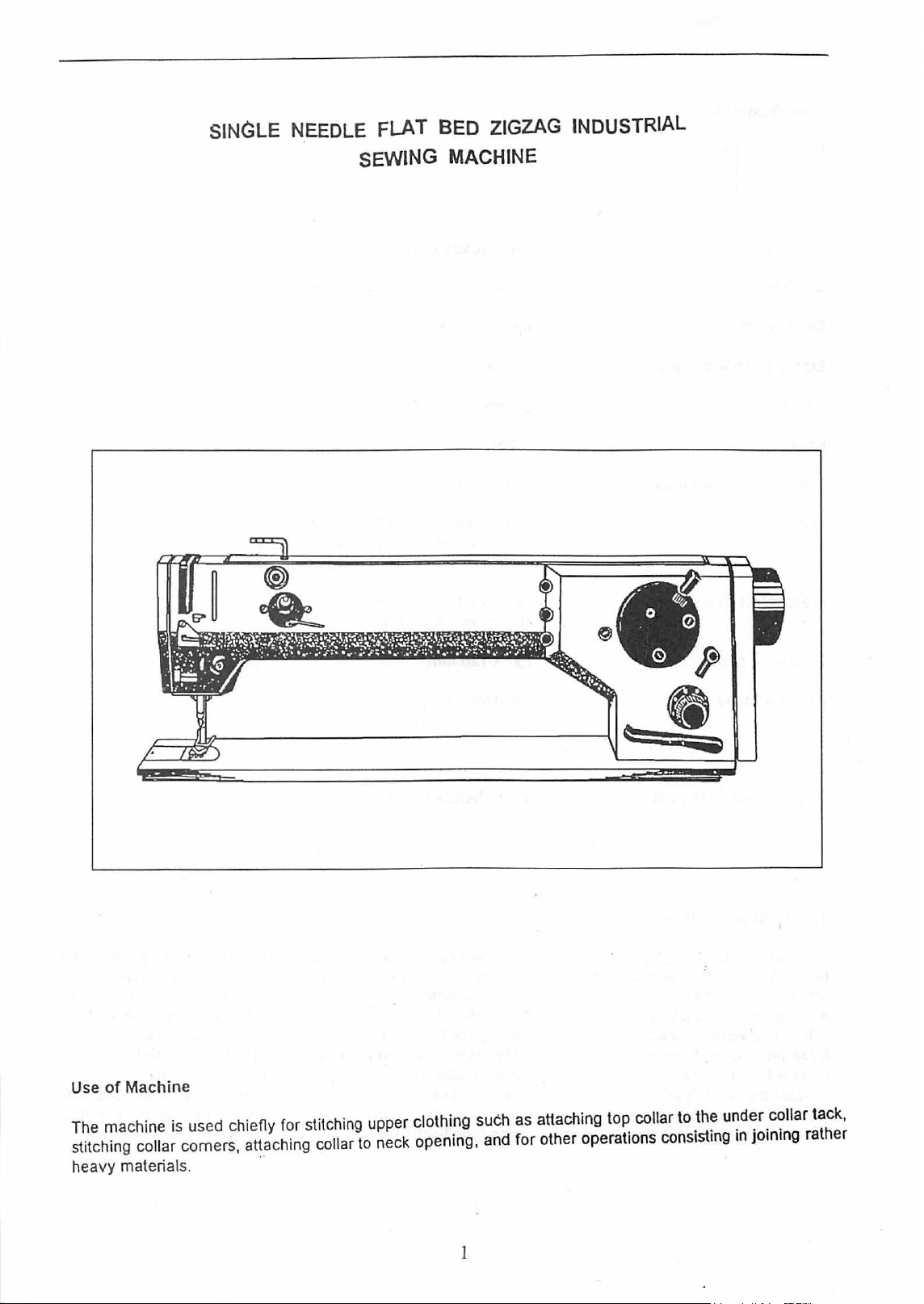
SINGLE NEEDLE FLAT BED ZIGZAG INDUSTRIAL
SEWING
MACHINE
Use
of
Mach
ine
The machine is used chiefiy for stitching upper clothing such as attaching top collar to the under collar tack,
stitching
heavy materials.
collar comers, attaching collar to neck opening, and for other operations consisting
..
1
in
joining rather
Page 3
Specifications
Machine
Stitch type
Stitch length
Stitch windth
Zigzag stitch width position
Needle
Hook
Thickness of
Threads
Presser foot stroke
speed
sewn
n:taterial
2200tpm
two-thread zigzag lockstitch
up
to 5
mm.
up
to
10
median
Schmelz
forward
mm
134-
35
and
Nos.
110-
R251
up
to 8
mm
cotton threads: 14,5 tex x
+ synthetic threads:
8
mm
with
10
mm
.witt\
hand
knee
PES
lever
lever
reverse
130
3-
25
tex x 1 x 2
25
tex x 1 x 3
35,5 tex·x 3
Clear
work
space
fMachine
+With synthetic threads,
Technical description
The
hook.
to
the
with
1.
It
for setting the stitch length
presser
increased
automatic lubrication of the
with
stand
be
sure
adequately
machine GG0028-L
situated
direction
a gear
is
adapted
a screw attachment for fixing a suspension-type lighting
foot.
strain
in
the
of
feed
ratio
of 2
for forward
by a hand
are
bed
seated
to
plate
of
sewn
1.
lever
is
designed
and
equipped
work.
And
from
and
reverse
and
stitch
or
by
in
antifriction bearings. The machine
hook.
In
750 x 120
standard steel profile
to
reduce
as
a flat-bed zigzag two-thread lockstitch
with
positive bobbin
The
drive
is
transmitted, from
the
upper shaft
sewing,
width.The
the
its
and
the
rever-Se
left-side treadle. The most important
basic
version.
mm
stand
the
machine
to
the
lower
front part ofthe machine
stitching is
the
machine
..
case
the
one,
has
speed.
opening,
lower
by
endless
actuated
a group
is
supplied
sewing
rotates
shaft
to
the
belt
column
by a hand
parts
of
wick
lubrication
without
machine.
in a plane
hook,
with
holds
lever,
mechanisms
lighting.
perpendicular
by
a gear ratio
control elements
the
and
but
The
rotary
gearwheels
of 1 to
lifting of
subject
separate
it
is
frtted
the
to
2
Page 4

Machine Equipments and
their
Use
Ordering No.
791
522
522
522
522
522 794 222
The Equipments are
124 027
791149
791
995 014 00
792112
35
001
00
010 00
01
0 00
Name
Stitching set - throat plate with needle aperture 1.8 mm;
needle Schmetz
Overedging equipment
Plug for the
Built-in
Suspension-type lighting
supplied on special order only.
hole overedging operations
fridional bobbin winder
of
work area
134-
35"No. 120
3
Page 5
I.
INST~UCTIONS
A.
GENERACINSTRUCTIONS
FOR SERVICING OF MACHINE
1. Read the instructions
2. During transport and while unpacking the machine, proceed
marks on the packing.
3. Report any damage which may have occurred during transport
forwarding agents at once.
report any discrepancies to
4. Having transported the machine to its work
Make sure that no machine part has become loose and that its mechanism is free
5.
Lubricate the machine daily!
Before lubrication. always check whether the lubrication places are clean. It is advisable to lubricate
frequentJy in
strain should be lubricated several times a day
6. Clean the machine
material. During the cleaning,
7.
Once a week, during through cleaning, carefully check the whole machine to see that no parts are
damaged and that
immediately.
be dismantled, thoroughly cleaned. all individual pieces and parts
and faulty
small quantities. Those parts
Once a year. a general overhaul
or
worn
of
the manual carefully and adhere to them.
in
accordance with the instructions and
to
the railway authorities
Immediately after unpacking, check the contents against the order and
us.
We
cannot recognise delayed claims.
site, remove the preserving grease coating and all dirt.
of
any foreign bodies.
of
the machine which are subjected to increased friction
as
needed. Top up the oil tank
daily, especially the parts which become choked by impurities from the sewn
carefully check that the machine parts have not become loose.
all machin.e machanisms operate correctly. Any faults ascertained must
-out
pieces repaired
or
replaced.
sho.uld
be carried out, i.e., the whole machine should
of
electrical equipment inspected,
ofthe
hook as needed.
be
or
to the
repaired
or
8.
Adhere to the safety
operation. Do
9.
Electrical equipment
electrotechnical and safety regulations.
plugging in that all switches are off. Never try to repair any defects
yourself but
10.
We
cannot assume any responsiblity
riot
call in
reg~lations.
remove covers
of
the machine should be kept in a good and safe state in accordance with the
an
expert electrician.
Never clean the machine or repair defects while the machine is in
or
other safety devices.
If
the machine is provided with a plug always make sure before
for
faults resulting from non-observance
of
the electrical equipment by
of
these instructions.
4
Page 6
B.
PACKING,
1.
2.
3.
4.
UNPACKING,
Packing
The
severe climate
Unpacking
When
arrived
authorities or to
to
prevent
and
To set the machine on stand
After
seated
stand
To
Fix
is
designed
of
me)chine
machine
of
taking
in
good
damage
report
any
the
machine
properly, a gap
plate
on
set and
the
fix
machine
as a stable
head
over
the
CLEANING
is
seated
conditions).
machine
the
machine
order.
Report
the
foiWarding
to
machine
discrepancy
has
been
of
approximately
whole
the machine
using
the
unit
of its
levelling
in a separate
immediately,
brought
with
AND
LUBRICATION
case,
from
the
railway
any
damage
agents
parts.
Futher check
to
cireumference.
foot
the
stand
which
immediately.
as
its
work
1.5
mm
oft
he
stand
requiring
the
authorities
we
cannot
site,
will
OF
stand
has
occurred
Unpacking
the
accessories
consider
set
it
on
appear
fitted
with
no
fixing
MACHINE
either
in
or
in
the
during
should
belated
the
rubber
between
adjusting
to
the
crating
works
the
be
of the
washers
the
bed
screw.
floor.
or
in a separate
ascertain
transport
carried
machine
daims.
of
plate
Otherwise,
whether
to
out
carefully
against
the
stand.
and
the
case
the
the
rim
the
machine
(for
it
has
railway
so
as
order
When
of
the
5.
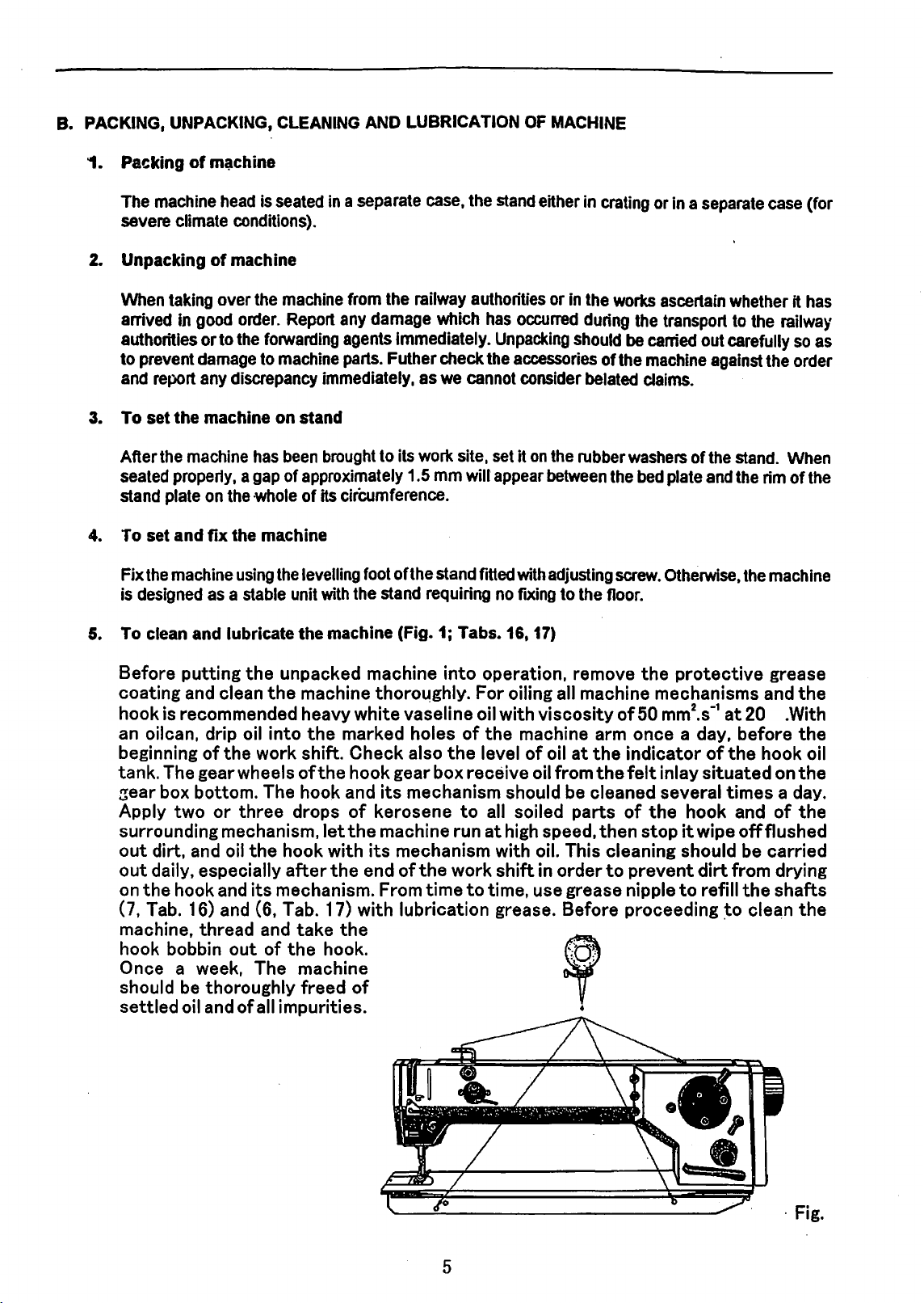
To clean and lubricate the machine (Fig. 1; Tabs. 16,
Before putting
coating and clean
hook is recommended heavy white
an oilcan. drip
beginning
tank. The
zear
box bottom. The hook and
Apply two
surrounding mechanism,
out
dirt, and
out
daily, especially
on
the
hook and
of
the
gear
or
oil
the
unpacked machine into operation, remove
the
machine thoroqghly. For oiling
vase
line
oil
into
the
marked holes
work shift.
wheels
three
the
of
drops
hook with
after
its
mechanism. From time
the
let
the
Check
hook
of
the
also
the
gear
box
its
mechanism should be
kerosene
machine run
its
mechanism with oil. This cleaning should
end
of
the
work
(7, Tab. 16) and (6, Tab. 17) with lubrication
machine,
hook bobbin
thread
out
and
of
take
the
the
hook.
Once a week, The machine
should be thoroughly
settled
oil
and
of
all
impurities.
freed
of
oil
with viscosity
of
the
machine arm
level
of
receive
to
all
soiled
at
high
shift
to
time.
grease.
17)
the
all
machine
of
50
once
oil
at
the
indicator
oil
from
the
felt
cleaned
speed,
in
order
use
grease
parts
of
then
to
prevent
nipple
the
stop
Before proceeding
@
1
•
protective
mechanisms
mm2.s
_,at
and
20 .With
a day, before
of
the
hook
inlay
situated
several
times
hook and
it wipe off flushed
be
dirt
from drying
to
refill
the
~o
cle~n
grease
the
the
oil
on
the
a day.
of
the
carried
shafts
the
5
·Fig.
Page 7
WarninJJ
Before proceeding to clean and lubricate the machine,
switch and hold your feet away from the machine stand treadles in order to avoid accidental
machine start by treadle actuation.
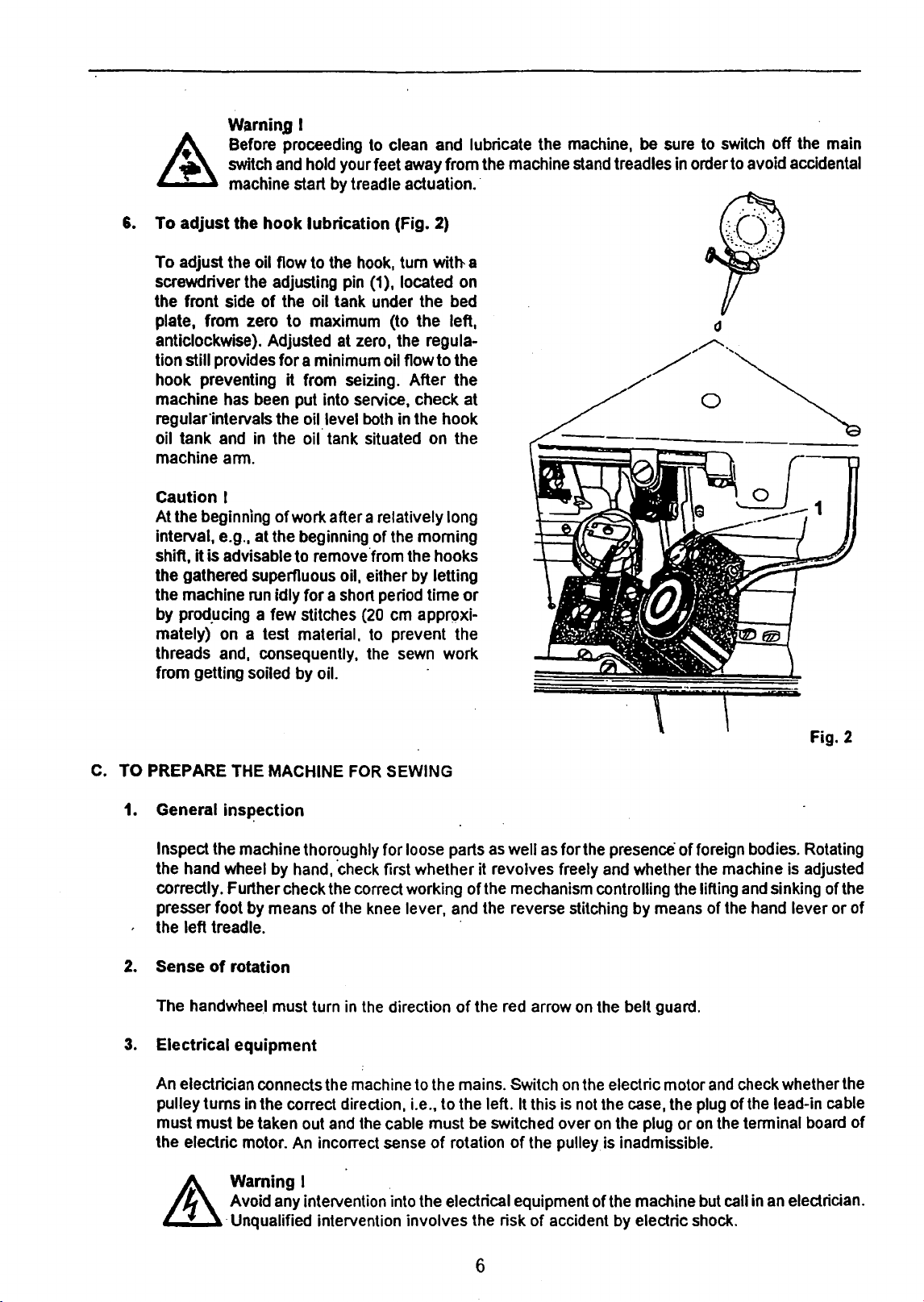
6.
To
adjust
To
adjust the oil flow to the hook, tum
screwdriver the adjusting pin
the front side
plate,
anticlockwise). Adjusted at zero, the regula-
tion
hook preventing
machine has been put into service, check at
regular-intervals the oil level both in the hook
oil tank and in the
machine ann.
the
from
zero
still provides
I ·
hook
lubrication
of
the oil tank under the bed
to
maximum (to
for
a minimum oil flow to the
it
from seizing.
oil· tank situated on the
(Fig. 2)
(1
), located on
with
the
After
left,
the
a
be
sure to switch
·
off
the main
Caution
At
interval, e.g., at the beginning
shift,
the gathered superfluous
the machine run idly
by prod.ucing a few stitches (20 em apprQxi-
mately) on a test material, to prevent the
threads and,
from getting soiled by oil.
C.
TO PREPARE THE MACHINE
I
the beginning
it
is advisable to remove.from the hooks
of
consequently, the sewn work
1. General insJ.!ection
Inspect the machine thoroughly for loose parts
the hand wheel by hand,
correctly. Further check the correct working
presser foot by means
the left treadle. ·
work after a relatively long
of
the morning
oil, either by letting
for
a short period time
FOR
SEWING
·check first whether it revolves freely and whether the machine is adjusted
of
the knee lever, and the reverse stitching by means of the hand lever or
or
as
well as for the presence
of
the mechanism controlling the lifting and sinking
of
foreign bodies. Rotating
Fig. 2
of
the
of
2.
Sense
The handwhee.l must turn in the direction
3.
Electrical equipment
An electrician connects the machine to the mains. Switch
pulley turns
must must
the electric motor. An incorrect sense
of
rotation
be
of
the red arrow on the belt guard.
in
the correct direction, i.e.,
taken out and the cable must be switched over
to
the left. It this is not the case, the plug
of
rotation
of
the pulley is inadmissible.
on
the electric motor
Warning I .
Avoid any intervention into the electrical equipment
·Unqualified intervention involves the risk
of
accident by electric shock.
6
and
check whether the
of
the lead-in cable
on
the plug or
of
the machine but call in an electrician.
on
the tenninal board
of
Page 8
7
4.
V-belt
The
of
power with losses reduced to minimum.
middle
will
increases both the power consumption and the wear
follows:
the lower belt guard the sheet piece fixed by screws to
falling out the groove
electromotor, fix
insert
correct tension, and mount the upper
and
its
tension
V-belt can
be
its holder after the loosening
part between the hand wheel and
yield some
Tilt
it
into the hand wheel groove. Lift the machine to its operational position, check the V-belt for
20
the machine head, screw out the screws (4), remove the upper belt guard (1), and from
(Fig.
3)
easily tensioned by means
of
two screws. The correct belt tension ensures transmission
To
the
mm sideways. Excessive tension
of
the pulley, remove the V-belt, mount a new one onto the pulley
it
by attaching back the sheet piece, pass it between the tank
belt guard.
1
I
4
...
Fig. 3
of
the electromotor that can be displaced in the guiding
check the tension
pulley;
if
the belt tension is correct, the pressed-on part
of
the V-belt reduces the machine output and
of
bearings. To remove the V-belt, ·proceed
the, stand plate and protecting the V-belt from
of
the V-belt, depress
it
lightly in the
and
stand plate, and
of
of
full
as
the
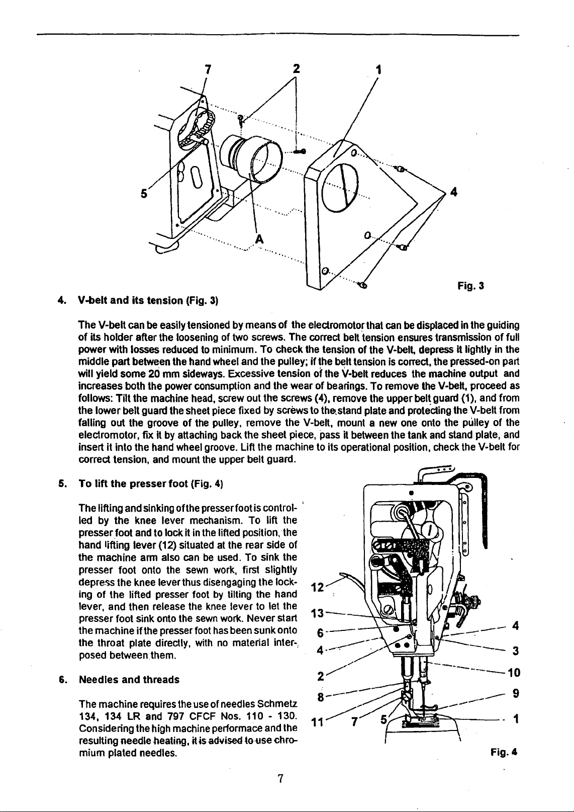
5.
To
lift
the
presser
The lifting and sinking ofthe presser foot is control- '
led by
presser.foot and to lock it
hand lifting lever (12) situated at the rear side
the machine arm also can
presser foot onto the
depress the knee lever thus disengaging the lock-
ing
lever, and then release the
presser foot sink onto the
the machine
the throat plate directly, with
posed between.them.
6.
Needles
The machine requires the use
134, 134
Considering the high machine performaee and the
resulting needle
mium plated needles.
the
knee lever mechanism. To lift the
of
the lifted presser foot
if
and
LR
foot
(Fig.
4)
in
the lifted position,·the
be
used. To sink the
sewn
work,
first
by
tilting the hand
knee
lever to let the
sewn
work. Never start
the presser foot
threads
and 797 CFCF Nos. 110 - 130.
-heating, it
has
been sunk onto
no
material inter-;
of
needles Schmelz
~s
advised to-use chro-
of
slightly
12
2
11
Fig.
4
7
Page 9
The
size of
ear.lt is
the needle ear
the beginning of stitching after
the
thickness of
excessive strain (impacts
by
friction
correct needle
stitches. Only high-class threads should
S-twist threads
thread.
the
needle ear
threads, the
7.
To insert the needle (Fig.
the
m~edle
advisabl~
but
between
course
should
A
coarse
reduces
sewing
depends
to
choose
·helping
sewn
work.
the
needle
follwed
be
thread or
speed
the
a rather thin needle, just permitting
to prevent the upper
A needle too thin
at
the
used
one
machine performance
should
4)
on
the size of
the
previous thread trimming.
needle punches into the
and
the
sewn
by
irregular formation ofthe
for the needle. white
which
has
be
reduced accordingly,
the
thread,
thread
with
work, etc.}
be
used.
Especially suitable
to overcome
and
since
from
respect.to
work,
and
upper
both
S-twist
considerable
incerases
it
must
pass
freely through
the
free
passage
being
threaded
The
needle
the
thickness of
upper
thread
exposed
to
to
the
thread
loops
are
conical
and
Z-twist
resistance
its trouble incidence. With synthetic
prevent
the
ofthe thread
out
of
the
needl~
size
should
sewn
tension, heat
risk of deviations
and
thread
threads
be
work
resulting
cross--wound
is suitable
when
passing
from melting.
adequate
is
the
needle
through
ear
subject
generated
from
the
in
skipped
bobbins.
as
lower
through
at
to
to
To facilitate
toward
between
of
the needle bar
directed
I
the
needle shaft
screw.
the centre ofthe
but choose it
switch and
stand treadles
chine start
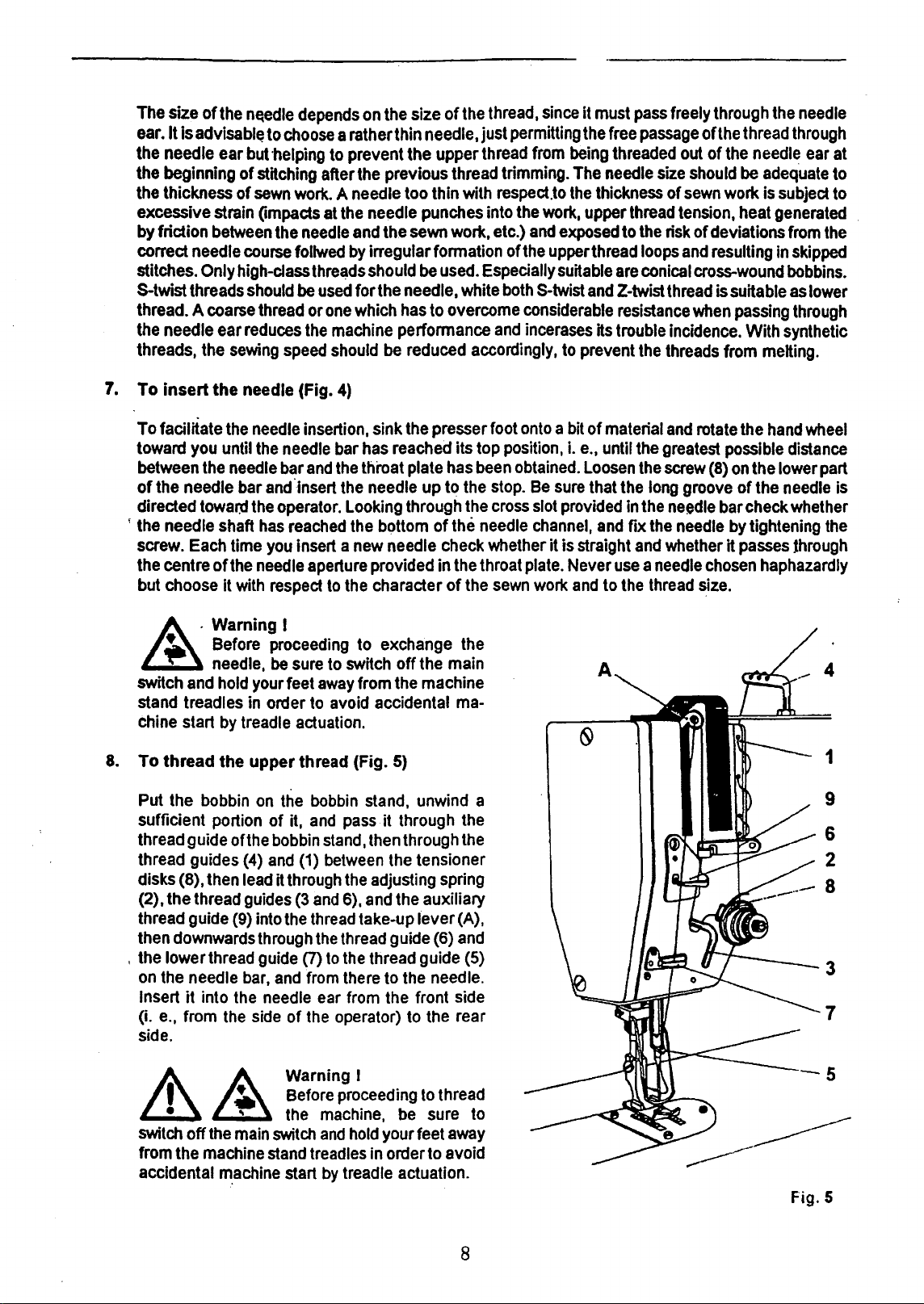
8.
To thread the upper thread (Fig.
Put
the
sufficient portion of
thread guide ofthe
thread guides
disks (8), then
(2), the thread
thread guide
then downwards
, the lower thread
on
the needle
Insert
(i.
e.,
side.
you
until
the
towar:d
Each
Warning I
Before
needle,
hold
by
bobbin
it into
from
the
the
needle
the
needle
the
has
time
needle
with
your feet
in
treadle
on
(4)
lead
guides
(9)
into
through
guide
bar,
the
side
insertion, sink
needle
bar
and
and
·insert
operator.
reached
you
insert a
aperture provided in
respect
proceeding
be
sure
order
to
actuation.
the
bobbin
it,
and
bobbin
and
(1)
it
through
(3
and
the
thread
(7)
and
from
needle
of
the
the
bar
has
reached its top position, i.e., until the greatest
the
throat plate
the
needle
Looking through the
the
bottom of
new
needle
to
the
character
to exchange the
to
switch
away
avoid accidental
pass
stand,
between
the
6),
the
thread
to
the
there
ear
from
operator)
off the main
from
the
5)
stand, unwind a
it through
then
through
the
tensioner
adjusting spring
and
the auxiliary
take-up
thread guide
l·ever
guide (6)
to
the
the
front side
to
presser foot
has
been
up
to
the
the
needle
check
whether it is straight
the
throat
of
the
machine
ma-
the
the
(A),
and
(5)
needle.
the
rear
onto a bit
obtained.
stop.
cross
sewn
Be
sure
slot
provided
channel,
plate.
Never
work
of material
Loosen
that the
and
use a needle
and
to
the
the
in
fix
and
long
the
the
thread
and
rotate
possible
screw
(8}
on
groove of the
needle
whether it
needle
chosen
size.
bar
by
the
hand
wheel
distance
the lower
check whether
tightening
passes
haphazardly
part
needle
the
through
4
1
9
6
2
3
7
is
Warning!
..
&~
switch
off
the
main
from the machine
accidental
~achine
Before proceeding
"
the
switch
stand
treadles
start
machine,
and
hold
by
treadle actuation.
be
your feet
in
order
to
thread
sure
to
to
away
avoid
8
Fig. 5
Page 10
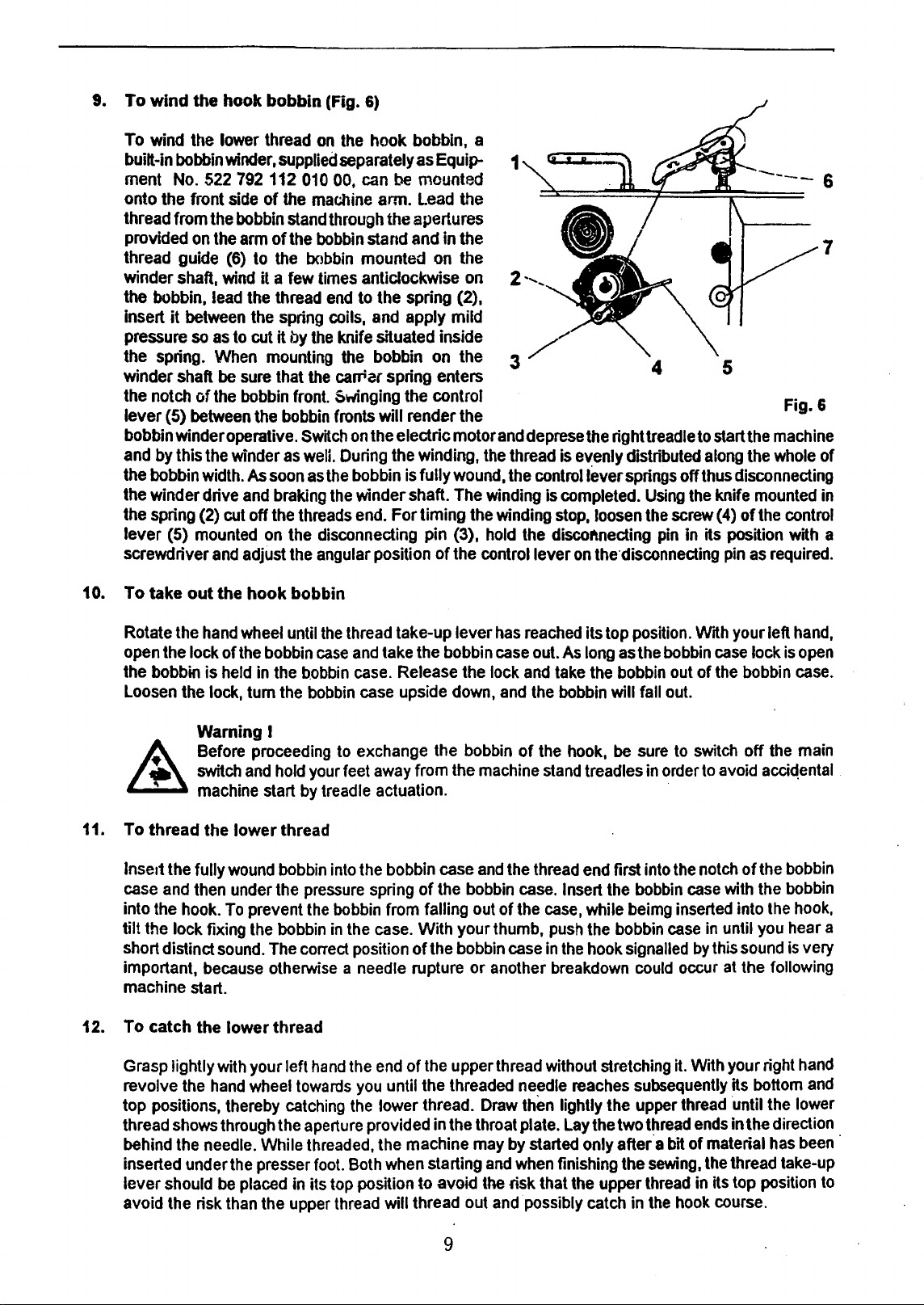
9.
To
wind
the hook bobbin (Fig.
To
wind
the
lower thread
built-in
ment
onto the front
thread from
provided
thread guide
winder
the bobbin, lead
insert
pressure so
the spring.
winder shaft
the notch of
lever (5)
bobbin winder operative.
and
the bobbin
the winder drive
the spring
lever (5)
screwdriver
bobbin
No.
it
by
shaft,
this
winder,
522 792 112 010 00,
the
on
the
(6}
wind
between
as
When
be
the
between
the
width.
(2}
cut
mounted
and
side
of
bobbin
arm
to
it a
the
the
to
cut
sure
bobbin
the
winder
As
and
off
on
adjust
6)
on
the
hook bobbin, a
supplied
the
stand
of
the
the
few
thread
spring coils,
it
by
mounting
that
bobbin
as
soon
braking
the
the disconnecting pin (3),
the
separately
can
machine
through the apertures
bobbin
bobbin
times
the
the
front. Swinging the control
Switch
welL
as
threads
angular position of the control lever
stand and in the
mounted on the
anticlockwise
end
to
knife situated inside
the bobbin
carriar spring enters
fronts will render the
on
During
the
bobbin
the
winder shaft. The
end.
as
be
mounted
arm.
Lead
the spring
and
apply mild
the
electric motor
the winding,
is
fully
For timing
Equip- 1
the
on
(2},
on
the 3
and
the
wound.
winding
the
winding
hold
2
deprese
thread
the
controiiEwer
the discoftnecting
the
right
is
evenly distributed
is
completed.
stop,
loosen
on
the'disconneding
4 5
treadle
springs
Using
the
pin
Fig. 6
to
start
the
machine
along
the
whole
off thus disconnecting
the
knife
mounted
screw
( 4) of
the
control
in
its position with a
pin
as
required.
7
of
in
10. To take
Rotate the
open
the bobbin is
Loosen
11. To thread the lower thread
Insert the fully
case
into
tilt the lock fixing
short distind
important,
machine start.
12. To catch the
out
hand
the lock of
the
lock, tum
Warning I
Before
switch
machine
and
then
the
hook.
because
the hook bobbin
wheel
until
the
the
bobbin
held
in
proceeding
and
start
wound
under the
To
prevent
the
sound.
lower thread
case
the
bobbin
the
bobbin
hold
your
by
treadle actuation. ·
bobbin
pressure
the
bobbin
The
correct
otherwise a needle
thread
to
feet
into
bobbin
in
take-up lever
and
take
case.
case
exchange the
away
the
bobbin
spring
from falling
the
case.
position of the
has
the
bobbin
Release
upside
from
case
of
the
With your thumb,
rupture or another
the
down,
bobbin
the
machine
and
bobbin
out
bobbin
case
lock
and
the
of
case
reached
out.
and
take
the
bobbin
of
the
stand
thread
case.
the
case,
push
in
breakdown
its top position.
As
long
as
the
bobbin
will fall
hook,
be
treadles
end
first into
Insert
the
while
beimg
the
bobbin
the
hook
signalled
the
bobbin
out
out.
sure
to
in
order
the
bobbin
case
could
Wrth
case
of
the
switch
to
avoid
notch
case
with
inserted
in
until
by
this
occur
at
your left
bobbin
off
of
into
sound
the following
hand,
lock
is
open
case.
the
main
acciqental
the
bobbin
the
bobbin
the
hook,
you
hear a
is
very
.
Grasp
revolve
top positions, thereby
thread
behind the
inserted under
lever should
avoid the risk
lightly
the
shows
needle.
with
hand
through
the
be
placed
than
your left
wheel
towards
catching
the
While
presser
in its
the
upper
hand
the
you
the
aperture
threaded,
foot.
Both
top
position to avoid
thread
end
of
the
upper thread without stretching it. With your right
until the threaded
lower thread.
provided
the machine
in
the
when
starting
will thread out
needle
Draw
thEm
throat plate.
may
by
started only after a
and
when
the
risk that
and
possibly
reaches
lightly the upper
Lay
finishing the
the
9
the two
upper
catch
subsequently
thread
thread
thread
in
bit
of material
sewing,
the
hook
ends
the
in
Hs
course.
hand
its
bottom
·until
in
the direction
thread take-up
top position
the
has
and
lower
been
to
·
Page 11
13.
Sewing-
Insert
gradually depressing the right treadle.
by
with the treadle has reached its lowest position.
is disengaged,
the material but guide it only. By pulling
it
in
collisions
machine
it, and cut the
To
Having
or
four
per
lubrication.
machine
II
..
INSTRUCTIONS
work
P.roper
the
material
case
of
of
stop,
observe:
put the
weeks. when the machine is running-in, increase its speed gradually from about 3 000 stitches
min. and check carefully its running. Throughout this time. pay'special attention
even
to
be sewn under the presser foot and switch on the electro motor. Start the machine
The
sewing speed increases up
By
releasing the treadle, the clutch
the
electromotor braked, and
a collisions with the edge
this kind burr the needle aperture which, in its
set
the needle
two
threads with scissors.
new
machine in use do not charge
By
keeping to these rules you will obtain a long service
at
its full perfonnance.
FOR
ADJUSTMENT
to
its top position,
OF
the
machine stopped. During the sewing, avoid pulling
the
material, you. bend the needle with the risk
of
the
needle aperture provided
lift
the presser foot, remove the sewn
After
that.
the
machine
it
fully from the very beginning. During
MACHINE
MECHANISMS
to
the
in
the throat plate. Repeated
tum,
causes thread ruptures.
is
ready
for
stitching
life
and perfect precision
maximum
ofthe
electromotor
of
work
from
another
the
to
the
obtained
breaking
After
machine
under
seam.
first
of
the
two
the
This
section
adjustments. requiring more time, should be carried out by a
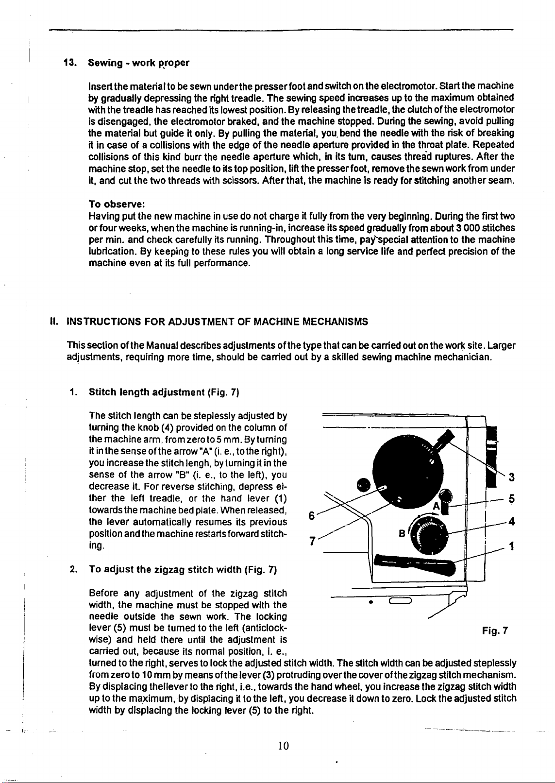
1.
Stitch
The stitch length can be steplessly adjusted by
turning the knob
the
it in the sense
you increase the stitch lengh,
sense
decrease
ther
towards the machine bed plate. When released,
the
position and the machine restarts forward stitch-
in g.
2.
To
Before any adjustment
width,
needle outside the sewn work. The locking
lever
wise) and held there until the adjustment is
carried out. because its normal position, i. e.,
turned
from
By
up
width
ofthe
Manual describes adjustments
length
adjustment
(4) provided
machine
arm, from zero to 5 mm. By turning
ofthe
arrow "A" (i.e.,
of
the arrow "B"
it. For reverse stitching, depress ei-
the
left
treadle, or the hand
lever
automatically resumes its previous
adjust
displacing
to
the
zigzag
t~e
machine must be stopped with the
(5)
must
be turned
to
the
right, serves to lock the adjusted stitch width. The stitch width can
zero
to
1 0
mm
by means
thelleverto
the
ma_ximum, by displacing it
by
displacing the locking
(Fig.
7)
on
the column
to
the right),
by
turning it in the
(i.
e.,
to
the left), you
lever
stitch
width
(Fig. 7)
of
the zigzag stitch
to
the left (anticlock-
of
the
lever
(3) protruding
the right, i.e., towards
to
the
lever
(5)
to
of
the type that can be carried out on the work site. Larger
of
(1)
6
7
over
the
hand wheel, you increase the zigzag stitch width
left, you decrease it down
the
right.
skilled sewing machine mechanician.
•
Fig.
be
adjusted steplessly
the
cover
oft
he zigzag stitch mechanism.
to
zero. Lock the adjusted stitch
3
5
4
1
7
10
------
-~----
Page 12
3.
Thread tension adjustment
The
tension
the middle layer ofthe
to the
thread tension,
By
turning
consequently.
inversely .lfthe
thread
of stitching.
of
right, i.e.,
the
the
tension
the
upper
clockwise,
use
screw
tension
lower
by
means
sewn
the
screw
to
thread
and
the
lower thread
material. To adjust the upper
to
increase the tension,
the
of
of
situated
right
the
lower thread that
tension
the
tensioner
you
has
in
increase
the
been
nut
must
middle
the
originally
will
be
or
part
pressure
passes
adjusted
be
sufficient,
so
Interrelated that
thread
inversely,
of
between
tension,
to
ttle
pressure
of
the
the
correctly'
as a rule,
the
tum
decrease
spring
spring
on
spring
and
the
to
resorte
stitch
binding
the
tensioner nut either
it.
To
adjust
the lower
on
the
bobbin
the
bobbin
the
bobbin
adjustment
the
case
.case
oft
he
desired
place
case.
and,
•.
and
upper
quality
in
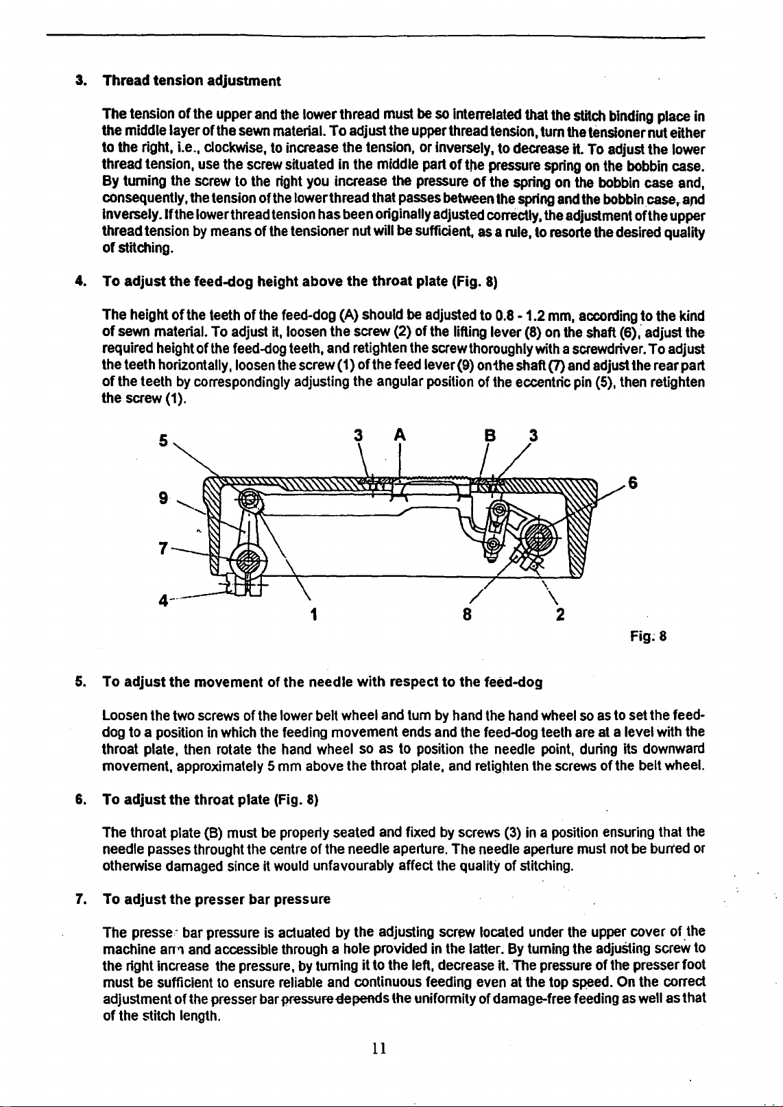
4. To adjust the feed-dog height above the throat plate (Fig.
The
height of
of
sewn
required
the
teeth horizontally,
the
teeth
of
screw
the
the
material.
height of
by
correspondingly
(1}.
teeth
To
adjust
the
feed-dog
of
the
loosen
feed-dog
it,
loosen
teeth,
the
screw
adjusting
(A)
the
and
(1) of
should
screw
(2) of
retighten
the
feed
the
angular
be
adjusted
the
the
screw
lever (9)
position
lifting lever (8)
thoroughly
5
9
7
4
1
8
8)
to
0.8 - 1.2
on
the shaft (7)
of
the
eccentric
mm,
according
on
the
shaft (6); adjust
with a screwdriver.
and
adjust
the
pin
(5),
then
6
Fig~
to the
To
adjust
rear part
retighten
8
kind
the
5.
To adjust the movement of the needle with respect
Loosen
dog
throat plate,
movement, approximately 5
6.
To adjust the throat plate (Fig.
The
needle
otherwise
7.
To adjust the presser bar pressure
The
machine
the right
must
adjustment of
of
the
to a position
throat
plate
passes
damaged
presse,-
arr'l
increase
be
sufficient
the
stitch
two
then
throught
bar
and
the
length.
screws
in
which
rotate
(B)
must
since
pressure
accessible
the
to
ensure
presser
of
the
lower
the
feeding
the
hand
mm
be
property
the
centre
it
would
is
actuated
through a hole
pressure,
reliable
bar
pr~ssur~-depends
belt
wheel
movement
wheel
above
8)
of
unfavourably affect
by
turning
the
seated
the
needle
by
the
and
continuous
so
throat
provided
it
to
11
to
and
tum
by
hand
ends
and
as
to
position
plate,
and
and
fixed
by
aperture.
adjusting
the left,
the uniformity of
The
the
screw
in
the
decrease
feeding
the feed-dog
the
hand
the
feed-dog
the
needle
retighten
screws
needle
quality of
located
latter.
even
the
(3)
in a position
aperture
stitching.
under
By
turning
it. The
at
the
damage-free
wheel
so
teeth
are
point,
during
screws
must
the
the
pressure
top
speed.
feeding
as
to
set
at
a level
its
of
the
ensuring
not
be
upper
cover of.the
adjuSting
of
the
presser foot
On
as
the
feed-
with
the
downward
belt
wheel.
that
the
burred
screw
the
correct
well
as
that
or
to
Page 13
8.
To
adjust
The hook must be so interrelated with the needle that at the moment when the hook point begins to
take
hook point, at
is not adequate
screw (6)
plate.
9.
To
adjust
up
in
height
the
upper
th~
maximum stitch width and in the left position
to
of
the carrier (13)
the·hook
the
needle
thread loop, the upper edge
this requirement, loosen the respective screws, remove the front plate, loosen the
course
bar
of
the needle
(Fig.
bar
4)
of
the needle ear is approximately 0.6
oft
he needle
(1
0), adjust the needle
bar
correctly, and mount the front
bar.lfthe
mm
needle bar height
under the
Adjust the stitch width to zero and tum the hand wheel towards you until the needle
bottom position and reascends by 2.8
axis, and the distance between the needle and hook must be
the throat plate, loosen the screws, adjust the angular position
the screws, and mount the throat plate.
10.
To
adjust
After
a gap
11.
To
adjust
If
the machine is adjusted correctly the feed-dog describes
reverse stitching. The adjustable eccentric is positioned by means
shaft
adjustable
Tt•e
eccentric
height adjustment
eccentricity
dog holder with the feed-dog to the centre
the screw(4)
the middle
the
hook
holder
the hook course adjustment, loosen the fixing screw and adjust the hook holder(2) so as
of
approximately
the
elliptical
a~d
commands the length
one, commands the corre,:;t interrelation between the
stationary eccentric is secured by two screws located in its collar. The eccentricity
!s constant so that the height
of
the feed-dog teeth. The adjustment should be carried out
of
the adjustable eccentric equals zero (so that
of
the lever(9) on the feed shaft (7). Ensure that the feed-dog reaches its top height about
of
the feed-dog movement.
(Fig.
0.
7 mm between the holder lug and the bottom
path
of
+ 0.2 mm. In this position the hook point must lie in the needle
0.1
mm
or
less.
of
the hook on the hook shaft, retighten
2)
of
the
feed-dog
of
feeding. Another eccentric, stationary and situated in front
of
the height
movement
of
of
the slot provided in the throat plate, having first loosened
(Fig.
8)
an
elliptical path both with forward and with
of
a pin in the aperture
major
and the minor axe
the ellipse remains the same regardless
no
feeding takes place) adjust the feed-
bar
reaches its
If
it is not the case remove
to
obtain
the inner part
as
of
the hook.
ofthe
of
the ellipse.
oft
he stationary
follows: When the
lower
of
the
of
the
12.
To
adjust
Loosen the screw
regulation knob to its zero position, adjust the traversable sleeve
position corresponding to zero, retighten the screw
equally long at forward and reverse stitching.
13. To
adjust
During the stitching, the gap between the sides
and the hook holder (7) is positively periodically opened by means
eccentric (6) to facilitate the movement
situated on the hook box at the end
holder and the recess provided
i.e.,
Screw out first the four screws (3)
inlay
by the pin (4) with the opening lever and adjust a gap
and the
opening
required to let
the
length
the
hook
the axial play between the
ou,t
of
it.
For
lower
~urface
lever
so as to produce a gap
the
of
feeding
of
the lever
opening
adjustment, loosen the screw (1) fixing the position
of
the hook by tapping lightly on the opening lever. At the same time, set the
thread pass. Having adjusted the opening lever. retighten the screw (1).
on
the pin
(Fig.
of
in
the inner part
Jug
of
of
the hook box cover(9), remove the cover, and take the lubrication
of
of
the reverse stitching hand.'lever, set the stitch length
of
9)
of
the groove provided
of
upper thread when leaving the hook. The eccentric is
the lower shaft. Adjust
of
the hook, and simultaneously, the opening lever,
the opening
0.5
mm
lever
of
between the recess
12
of
the adjustable eccentric to a
the lever, and check whether the feeding is
in
the inner part of the hook
of
the opening
first
the gap between the lug
and the face
0.8 mm between the lug
of
the inner part
of
the bobbin case (5) contacted
of
the inner part and the hook holder
lever
(8) and of
of
the hook
of
the hook.
of
the opening lever
Page 14
Before
remove
opening
carried
sewn
eccentric (6)
lower shaft
inner part of
moment
across
and
correct
hook
proaches
around
thread.
on
move
adjustment
insert the lubrication inlay,
cover of
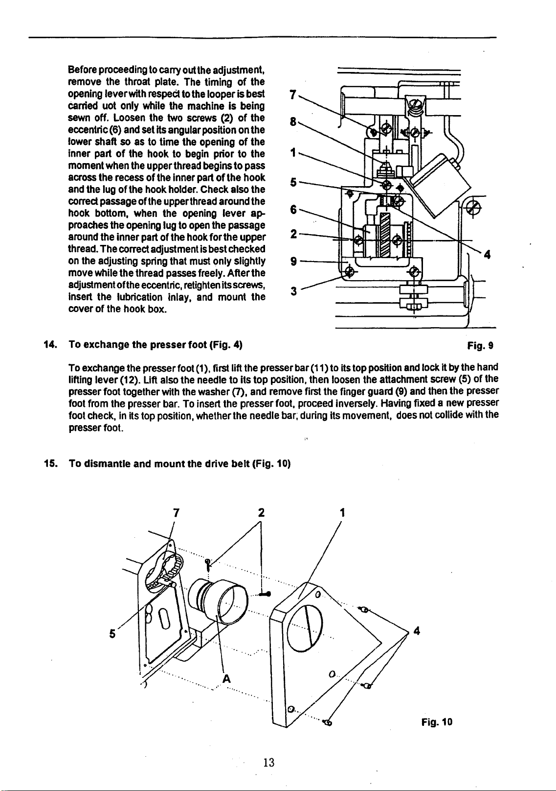
14.
To exchange the presser foot (Fig.
proceeding
the
lever
uot
off.
when
the
the
lug
passage
bottom,
the
The
the
adjusting
while
the
throat
with
only
Loosen
and
so
as
the
the
recess
of
the
when
the
opening
inner
correct
the
thread
ofthe
hook
to
cany
plate.
respeCt
while
the
the
two
set
Hs
angular
to
time
hook
upper
of
the
hook
holder.
ofthe
upper
the
lug
part
of
the
adjustment
spring
that
passes
eccentric,
box.
to
thread
inner
out
the
The
timing of
to
the
machine
screws
position
the
opening
begin
begins
part
Check
thread
opening
to
open
hook
is
must
freely.
retighten
and
adjustment,
the
looper is
prior to the
of the hook
the
for the upper
best
only slightly
Is
being
(2) of
on
of
to
also
around
lever
passage
checked
After
its
screws,
mount
4)
best
the
the
the
pass
the
the
ap-
the
the
7
8
1
5
6
2
9
3
Fig. 9
To
exchange
lifting lever (12). Lift
presser
foot
from
foot
check,
presser
15.
To dismantle and mount the drive belt (Fig.
the
presser
foot together
the
presser
in
its
top
foot.
foot (1), first lift
also
the
with
the
bar.
To
insert
position,
whether
needle
washer
to
(7),
the
the
the
presser
its top
and
presser
needle
bar
position.
remove
foot,
proceed
bar;
10)
(11)
then
first
during
to
its
loosen
the
finger
inversely.
its
movement,
top
the
position
guard
and
lock it
attachment
(9)
and
Having
fixed a new
does
not
4
screw
then
collide
by
(5}
the
the
hand
of
presser
presser
with
the
the
13
Fig.10
Page 15
Screw out the three screws
onto the suppoting
tbe two screws
Pass the drive belt (7) through the aperture thus created in the machine ann, set it
wheels,
screw
the upper shaft,
its operational position, i.e., into
and
(2), considered
.pin
(2),
and
mount the complete
when
(4),
remove the belt guad (1) from the machine ann, tilt
situated
remove the hand wheel from the machine arm and from
in
tightened. Retighten the screws (2) of the
the
on
the bed plate, take the V-belt out of the
hand
sense
of rotation of the
the
rim of the stand plate,
wheel back
on
the upper shaft
hand
wheel, comes to sit
hand
and
mount the belt
hand
in
such
wheel, tilt the machine
the
wheel
the
a position that the first
on
the
guard.
machine
groove, loosen
upper shaft (5).
on
small surface of
the
two
back
head
belt
to
16. To
17. To
adjust
(Fig.
Adjust the zigzag stitch
reaches
longitudinally
work) screw out the two
3).
and
machine
screws
To observe:
When tightening the adjustment screws
completely but leave a minimum play between ihem
the transverse movement of
Absence
damages to the needle bar mechanism.
adjust
(Tabs.1,
Adjust the zigzag stitch
reaches its bottom position.
the transverse
the cover
part. Then loosen
holder (4)
the plug. Check the needle
between the needle
adjusted at zero, the needle
wheel rotation.
adjusted
the needle punches longitudinally
4)
to
the
zero
width
Hs
bottom position.
and
transversely.
screws
finely adjust the angular position of the screws (4)
arm
so
as
to
set
(2
and
3) and mount
of
play
between
the needle punches transversely into the centre
3)
to
and
in
the
(25, Tab. 1)
so
as
If
by
an
experienced
out
with
a screwdriver the two
to
set
the
and
it
does
The
needle should
In
case
of
the
front plate, remove
the
needle longitudinally into
the
front plate.
the
needle bar holder required for the
the adjusting screws (4)
the
zero
width
In
this position, the needle should
longitudinal direction. If this
of
the
front part of
needle
the
react,
punch
slot
bar
the
sewing
at
the
position
side
in
with
the needle should
basic zero position of
machine mechanician since
into
the centre
and
tum the
of
longitudinal deviation (i.e.,
(4) for adjusting the needle position,
and
turn
the
screws
centre of
at
the maximum stitch width
each lateral position of
handwheel
be
in the centre of the throat plate slot
the
latter, loosen the securing screws (2
both
the
centre of
and
the
needle bar holder
and
the needle bar holder involves the risk of
the
hand
wheel
is
not
the
machine arm,
(27, Tab. 3)
the
throat plate groove,
react
the
zigzag stitcfl tjrive
until
on
the front
until
be
case,
and
and
the
with
such
at
of
the
the
.needle
in
the
and
the
front plate slot. Retighten the
zigz.ag
of
the
slot
the
needle bar with
the
centre of
screw
out the screw {26)
the opposite
adjust the complete needle
and
and
be.sure
needle.
no
lateral
adjustment
slot
of
the
throat
bar
with·
feed
direction of
on
the
rear side of
do
not
tighten them
in
order not to obstruct
stitch.
of
the
throat
the
groove
plug,
out of
reinsert the cover
that
there
V'iiti1
zigzag slitch
movt:i•lf:iit
mec:nanisrr;
is
rather extensive.
plate
the needle
both
sewn
and
the
plate
the
needle
both
and
take
its
rear
bar
and
is a play
width
k ihe
hand
.>hould
in
be
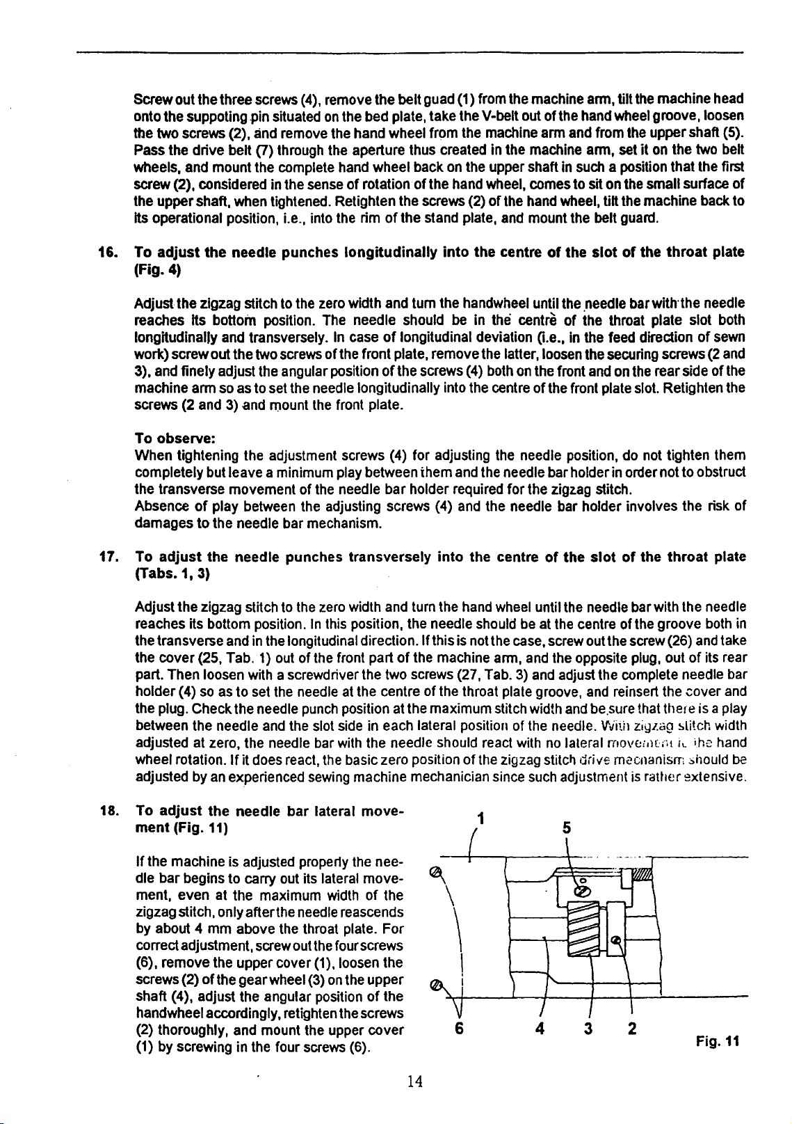
18. To
adjust
ment (Fig.
If
the machine
dle bar begins to carry
ment. even at the maximum
zigzag stitch. only after
by
about 4
correct adjustment,
(6), remove the upper cover
screws (2) of the gear
shaft (4), adjust the angular position of the
handwheel accordingly, retighten
thoroughly, and mount the upper cover
(2)
{1)
by
the needle bar lateral move-
11)
is
mm
screwing
adjusted
above
screw
in
the
property
out
its lateral move-
width
the
needle
the
throat plate. For
out
the
(1),1oosen
wheel
(3)
on
four
screws
the
nee-
of
the
reascends
four screws
the
the upper
the
screws
{6).
\
\
\
I
6
1
14
4 3 2
Fig.11
Page 16

19. To adjust the control force required
(Figs. 12, 13)
for
stepless adjustment
of
the zigzag stitch width
For the stepless tilting of
stitch mechanism contains
Turning the
required to
stitch width
by
out
that
can
cover (1, Fig. 13)
control force, first take the
purpose, screw
out
the three attachment
out
the
lever
stitch mechanism that
screw
adjust
must
the lever (2)
be increased
securing
(7, Fig. 12}
to the right
the
stitch
be tomed
whose
up
shows
out
the
screw
{3,
and
take
can
two
screws
3 2
the
zigzag
the
increases
windth.
to
the
extreme
to
1 0
the
approximative stitch
complete
screws
Fig.
the
pin
be
then
stitch bracket,
braking
mm
13}
roller (1) with
the
A mechanism actuated
left prior
left position, defined
by
displacing
zigzag stitch
(2}
from the
(3,
Fig.
12) from
on
the
pin
(6, Fig.
taken
13)
outofthe
pressure
to
proceeding to
the
width
mechanism
body
the
(5},
remove
out
of
engagement,
machine
the
inlay
the
spring
exerted
the
by a stop,
lever
value
of
the
body
ofthe
the
5
(1
0,
Fig.
(5)
and
on
the
roller
by
the
lever (7)
stitch width
produces
to
the
right.
at
each
out
of
the
mechanism,
zigzag
pin
from
the
thus
releasing
arm.
For
the
12)
of
the
body
of
the zigzag
with
the
adjustment screw (8}.
and,
consequently,
serving
adjustment
the
The
lever position. To adjust
machine
remove
stitch
guiding
assembly,
to
zero
zigzag
number marking
ann
column.
the
cover (1),
mechanism,
(4),
loosen
the
body
proceed
fix
the
which
stitch
then
ofthe
the force
adjusted
is
the fixing
inversely.
carried
width
on
the
the
For this
screw
screw
zigzag
5~~
'(8
20. To adjust the tooth play
The
tooth play of
12}.
To
cover
(1
pin
(6,
Fig.
cam
and
by
throughly tightening the
21.
To adjust the position
adjust
),
and
12)
the gear
1
the
the
toqth
loosen
adjust
wheel
zigzag
play,
the
the
9
4
3
:
•
7
Fig.
12
of
the zigzag transmission mechanism (Figs.
stitch
transmission
first
screw
outthe four attachment
screw
(5)
tooth
play
(3,
Fig.
screw
of
the needle
located
of
11)
(5).
in
the
the
zigzag transmission
mounted
on
barwith
3~
mechanism
lug
oft
the
upper:shaft (4),
respect to that
he
machine
is
mechanism,
actuated
screws
11,
12)
by
the
eccentric
(6,
Fig.
11},
remove
arm.
By
turning
i.
e.,
then
lock
of
the hook shaft (Figs.
then
between
the
adjusted
pin
the
the
eccentric
the
complete
1
Fig.
13
(6,
Fig.
upper
position
14,
15)
After a substantial adjustment of machine mechanism
bar position
needle bar
the
bed
lug
of
plate
the
with
axis.
and
bed
plate. Lock
respect
For
adjustment.
the
hook
to that of
gear
the
the
loosen
box.
gear box .position
hook
shaft.
the
two
In
correct position,
The
screws
by
tightening
should
hook
(1,
Fig.
the
be
shaft
14)
hook
the
checked
15
the
axis
is
ensuring
gear box
two
screws
median
displaced
the
is
indired contact
(vertical)
to
locking joint
(1).
the
needle
left of
between
with
the
the
Page 17

0
To
observe:
If
the
gear
box
of
the hook has been removed be sure to reinstall it so as to ensure the parallelism
the hook shaft axis with the bed plate plane. Check
laid onto the upper surface
the value
(B, Fig. 15).
of
the bed plate and onto the worked surface
Fig. 14
the·
parallelism for instance by means
of
the gear box, and measure
oftwo
of
shafts
To
22.
adjust
spring
Loosen the screw (1) and take the complete
upper thread tensioner out
arm.
spring (2), loosen the screw (3)
(4) and adjust the angular position
(5). Turning the pin to the left
spring
ment is adjusted the spring arm stroke as
Displace the right-side sliding plate, sew a few
stitches, and check the adjustment
adjusting spring. With correct
thread passing around the hook bottom
produce a slight movement of the adjusting
spring without being stretched.
the
operation
(Fig.
16)
To
adjust the tension of the adjusting
tension, and inversely. By this adjust-
of
the
of
the machine
on
will decrease the
adjustment, the
adjusting
the bushing
of
the pin
well.
of
the
shall
Fig.15
Fig.16
16
Page 18

23.
Electrical equipment
of
machine
The machine is fitted
of
the machine should
To change the
or at the terminal
lead-in cable out of
Ill.
MAINTENANCE
1. Machine cleaning
Plain machine lines help
remove the
daily.
with
an
sense
board
of
the
be
kept
rotation
of
socket.
electromotor mounted
in
good
state according
of
the electromotor cllange over
the
electromotor.
In
in
the
to
the
the latter case,
Warning I
Avoid
any
intervention
Unqualified intervention involves the risk
waste
between
to
the
keep
into
the
clean
feed-dog
electrical
outer machine
and
equipment
the throat
of
accident
parts.
plate.
Warning I .
Before
switch
machiAe
proceeding
and
hold
your
start
by
to
clean
feet
treadle
and
away
from tile
actuation.
lubricate
machine
the
machine
electrotechnicaland
Otherwise.
machine,
stand
the
do
not omit
ofthe
by
From
treadles
stand.
lead-in
first
machine
electric
time
to
the
machine
be
sure
in
The
shock.
order
electrical equipment
security
cable
to take the
but
call
time.
to
switch
to
either
in
an
it
is
necessary
sould
avoid
regulations.
at
the
plug
electrician.
be
cleaned
off
the
accidental
plug
of
the
main
to
2.
General overhaul and repair
Should
faulty pieces
tested. The electromotor
overhaul of
major defects for another
3.
To store the machine
After the machine
exchanged,
all the tools
be
carried
out
exchanged
the
machine
has
if
any.
The
and
accessories.
of
once a year.
and
due
and
the
should
been
machine
year.
set
be
out
should
the machine
The
machine
repairs cerried
electrical equipment
carried
of operation, it
be
should
out.
out
so
thoroughly
should
then tested,
be
set
The
machine
should
be
coated
out
of
be
inspected
as
to
enable
cleaned,
with
operation.
should
the
inspeded,
protective
cle~~ed,
be
then
and
tested.
machine
grease,
dismantled,
assembled
The
to
r:un
·and
faulty
and
stored
an~
general
without
pieces
with
17
Page 19

IV.
FAULTS AND HOW TO REMOVE THEM
Fault
a)
Heavy machine run
b)
Slow
machine
c)
Upper
thread
start
breakage
Cause
The machine has been out
for considerable time, dried
and impurities deposited in the
bearings.
Insufficient belt tension.
of
use
oil
1. Slashed thread guides.
2.
Too sharp hook point.
3. Faulty feeding.
".
Faulty
or
5.
lncorrectupperthreadtension.
6. Bad needle quality
needle.
upper
needle threading.
thread guiding
or
bent
7. Thread size is inadequate to
of
the thickness
rial.
8.
Machine considerably
9. Thread wound
10. Thread is too thin
enough.
sewn mate-
~oiled.
on
the hook.
or
not strong
Removal
Inject some drops
into all lubrication holes and
sliding surfaces and let the machine run rapidly so
lubrication holes in the bearings.
Then
oil the machine carefully
(see par.
Increase the belt tension by tilting
the electromotor.
1. Ascertain
5, page 6).
and
of
kerosene
on
as
to clean the
exchange them.
2. Repair it.
3. Adjust it see par. 5, page 12.
4.
Thread the upper thread correctly see par.
5.
Adjust it see par. 3, page 12.
6.
Exchange
8, page 9.
the
needle see par.
7, page 9.
7. Use adequate threaa.
8. Unscrew the throat plate, clean
the mechanism, and set the
throat plate see par.
6, page
12.
9. Remove the thread.
10. Use adequate thread.
d)
Lower
thread
breakage
1. The thread is incorrectly threa-
ded into the bobbin case.
.
2.
Thread is too thin
stroung enough.
3.
Thread is wound incorre-::tly
on the bobbin.
or
not
4. Damaged bobbin.
5.
e)
Skipped
stitches
Too sharp pressure sp:-ing
the bobbin case.
1.
Needle inserted inr.orrectly
2.
Blunt
or
bent needle.
3. Slashed
4.
Excessiv~=.;
the throat plate.
or
broken
needie apeiiure in
hoo~.
on
point
18
1 . Thread it correctly see par.
11, page 10.
2. Use adequate thread. ·
3.
Wind it
rectly.
4.
Exchange it.
on
the bobbin cor-
5. Exchange the spring.
1 .
Insert
it
correctly see par.
page 9.
2.
Exchange it see par. 7, page
7,
9.
Exchange the hook.
3.
4. Exchange the throat plate and
correctly.
set it
Page 20

Fault
f)
Needle breakage
Cause
5.
Broken adjusting spring for
upper thread tension.
6. Needlebarpositionedtoo
or too low.
7.
Overturned hook, incorrect
hook course.
8.
Soiled hook mechanism.
1.
Feed-dog positioned
2. F
au
tty
attendance-pulling the
material.
3. Needle too thin with respect
to material.
too
high.
4. Needle inserted incorrectly.
5. Loosened throat
6. Excesive upper· thread ten-
sion.
plate.
high
Removal
5. Exchange the spring
just the upper thread tension
see
par.
6. Adjust it
3, page
see
12.
par. 8, page 13.
7. Adjust the hook course
par. 9,
8.
Clean
page
13.
it
with kerosene
it with oil.
1. Adjust it
page
2. Let the material
3.
Exchange
7,
4. Insert
page
5.
Set the throat plate correctly
see
by
6. Adjust it
12.
page
9.
it
9.
par.
screws.
in
height
the
needle
correctly
6,
page
see
par.
see
pass
see
12
3,
and
page
and
and
par.
freely.
see
par.
par. 7,
fix
ad-
see
oil
4,
it
12.
g)
Heavy and irregular feeding
h)
Stitch
material
forming
below
sewn
1.
Feed-dog positioned
2. Worn-out feed-dog.
3.
Clogged or blunt teeth offeeddog.
4. Insufficient pressure of
er foot.
1. Tensioner discks
upper thread.
2.
The
thread does
smoothly around the looper
or catches the bobin
3.
The upper thread
between the tensioner disc.
4.
Thread broken
tween the tensioner disks.
5.
Incorrect proportion
the
upper
tensions.
and
too
press-
slashed
not
case.
is
not
thread
and
caught
between
lower thread
low.
by
pass
be-
1. Adjust it
page
2.
Exchange
Clean
3.
dog.
4.
Increase
7.
1.
Exchange
upper thread tension
3,
2.
Clean
bobbin
3.
Thread
4.
Clean
adjust it
5.
Correct
3,
time to time.
in
height
12.
it.
or exchange the feed-
the
pressure
page
12.
them and adjust
page
12.
the
hook
case.
it correctly.
the
thread
see
par.
the
proportion
page
12
and
see
par. 4,
see
par.
the
see
par.
and
adjust
the
tensioner
3,
check it from
page
see
and
12.
par.
i) Stitch
material
fonning
above sewn
Damaged spring
bin
case, the lower thread
braked insufficiently.
on
the
bob-
is
1.
19
1.
Exchange the spring.
Page 21

Fault
Cause
2.
Lower thread is not threaded
under the spring
case.
3.
Lower thread broken
caught under the spring
bobbin case.
4.
Incorrect proportion between
the upper and
tensions.
5.
Premature feeding.
ofthe
lower thread
bobbin
and
of
the
Removal
2. Tread it correctly.
3.
Remove the thread.
4. Correct the proportion see par.
3.
page 12.
5.
Adjust it see par.
5.
page 12.
j)
Locked
hook
Thread rests caught in the hook.
Rotate the hand
diresction regardless
siderable resistance until the
caught
pieces. Remove them and start
the unthreaded machine. Let
run
three drops
in
thre~~
for a period. then drip two or
par.
5,
page 6 onto the hook.
wheel in each
of
the con-
rests are cut to
of
oil recommended
it
20
Page 22

TABLES
OF
PARTS
Page 23

tab.
1
2
522980
522080
3
4 321161
5
522080
6
522080
7
522080
9
522080
10
522080
11
522080
522080
12
13
522080
522080
14
15
522080
16
522080
17
522080
18
522080
19
522080
20
522080
21
522080
22 722923
23
522080
25
522080
522080
26
831348
123117
001000
840073
313204
161138
815007
120248
7211.73
827180
123122
111227
271184
821115
821on
821113
190368
120361
823115
126063
132112
831494
123166
Page 24

I
I
~-~
i
I
!
I
l
i
I
/
I
i
-
3
4
5
--·
522080 2
522080
52208
522080
--
- -
tab.
--··,.
2
-
0
·-
-
111
227
945100
945188
272039
I
80
080
080
822424
131027
310428
120350
025
244
264294
828079
828080
262074
1950-1'1
171
037
I
l
I
i
I
I
I
I
I
. I
II
10
11
12
13
14
1•~
18
19
20
21
22
522080
522080
522080
5220130
522980
315231
522 0
522
522
522 080
522080
..
fJ
I
I
L __
---
I
I I
I I
I
i
-
__
_)
\.__
_·--·
···
--
)
Page 25

tab.3
x··
..
··
..
~
.•'
..
·
..
·
...
··········
27
...
...
..
·
.
·.
..
...
·
..
·······
··
......
...
·······
...
:
:
:
:
:
:
:
:
~
··.;
·:x
. .
: · .
...
·
273111
1
2 522080
522080 190593
3
4
522080 264281
522980 035654
5
6 522080
7
522080
8 522080 613468
522080 343074
9
10
522080
11
321861 953200
12
522080
13
522080 945296
14
522080 111094
15
522080 672174
16
311732
17
522080 124050
18
522080 111230
19
522080 260483
20
522080 870170
21
522980
22
522980 025249
23
522080 827194
24
522080
25
522080 1631'06
26 522080
27 311515
28
522980 036122
025410
441560
310377
441308
265037
112115
910040
025248
260510
161138
601606
~
·········
I--~
Page 26

r------
tab.4
I
I
4
522080
5
522080
6
522080
7
522060
9
5220BO
522080
12
13
522080
18
522080 111273
522080
v
1"
20
522080
2'i
522060
522080
23
5220b,··
24
522
26
527
27
98(:,
98~
953159
122007
111238
112015
138009
120006
953139
111125
120216
120220
111214
i 1 j 295
043343
035318
I
I
I
i
I
I
I
i
I
l
'
'------·---
I
I
\____
J
·--
Page 27

(
I
I
-
\
.
···-----
tab.5
I
1
2
3
4
5
6
7
8
9
522
522080
522 080
522
522080
522080
708420
01,5x
283366
0 3,5/0 4,8
522080
080
980
··120276
190353
646104
021394
413
424051
002105
250
mm
002001
x 190
394167
311
mm
31
11
708420
01,5
x 80
12
522080
13 522
14
15
16
17
18
19
20
21
22
23
24
25
27
28
29
31
32
33
37 522 980
080
522080
522080
522080
522980
522080
522080
283366
0 3,5/0 4,8
708420
3x250mm
e
522080
522080
522080
522080
522080
522080
080 112014
522
522080
522080
080
522
002105
mm
111229
113115
111248
391176
124050
035499
627170
136082
002001
x 70
mm
130003
111122
421341
410595
648132
120589
613 519
135029
328005
120062
727
044
Page 28

·!
...
····~
.·
-·
...
... . . . . :23
..
~--
tab.6
·~
1 522080 945317
2 522
3
4 522
5
6
7 522
8 522080 120221
9 311732 910060
10
11
12
13
14
15
16
17
19
20
21
23
24
25 522
26
27 522 080 383168
28
29 522080 120217
30
080 623 249
522080 326213
080 283152
522080 113122
522080 113123
080 264296
522080 120543
311732 910040
522080 136023
522080 615021
522080 112014
522080 190554
522080 120239
522080 120050
522080 392105
522 080 421330
522080 839215
522 980 044 713
522 080 613453
080 271337
522 080 190 346
522080 814014
522 080 436
331
Page 29

tab.
7
r
I
i
1
522080
2 522080 322247
522080 646120
3
4
522080 442530
5 522080 839010
522080 161236
·6
7 522080 126101
8 522080 952251
9
522080
10
522080 954048
11
5~2080
12
321841 020000
13
522080 260139
14
522080 111099
15
522080
16
522080 174066
17
522080 120219
18
522080
646027
120543
123130
120276
613472
Page 30

tab.8
283366 002001
e3,5/e4,
708420
2
2x
e
3
283366
3
8
4
5
6
7
8
9
10
11
12
13
14
• •
708420
e2x270mm335101
522080
22
5
522 080 334
522080 161237
522
522
522080 612342
22080
5
522
522080
8 100mm
x 130002
140mm 002001
e4
8x210mm
5/
080
080 422184
080 163 093
080 120 233
30002
1
131
~91
152 099
097
424051
47
48
49
50
51
52
53
522080
522080
273111
522080
522080
273111
522980
141223
190526
001000
335105
120221
007000
024263
16
17
18
19
20
23
24
25
26
27
28
29
33
34
35
522080
324311
522980
522080
738923
522080
522080
522080
522080
522080
522080
425111
522080
522080
522080
522980
522080
522080
522080
522080
522080
522080
522080
e2x150mm
951327
010000
035598
945326
002000
120291
161233
646027
322~47
190359
112101
041000
112013
436000
320289
021394
410595
648132
120589
613519
132203
318210
130002
Page 31

tab. 9
I
I
I
.···.
·.
·.
. .
·~
. .
·.
• ...
·..
~
..
··'@
:32.
1 522080
522080 192061
2
3 522080
4
522980
5 522080
522080
6
522080 233031
7
522080 112013
8
14
522080 627023
15
522080 141102
"16
311732
17
522080 120221
18
522080 613328
311728
20
27
522080
28
522980 022126
522980
29
522080
30
32
522980
34 522080
161142
441187
049785
120246
342258
910070
502537
120227
043301
260383
044714
613373
Page 32

tab.10
I
I
l
_______
______
I
I
I
I
I
I
I
__..
\
J
--
283 366
o
3,
2
708 420 i 30
~~:
2x140mm
28335€ 002001
3
4
G
5
7
8
11
12
~
~
15
'I)
H
18
1&
20
21
:a
23
3.5/ID 4,8 x 75
"
708420 13
.:3x300
283366 002001
!J 3,5/0 4,8x1
2080
52
283366
3,5/~
.,
522080
'1
08420
J
z 2
52
2 080
522080 324095
3
~
2080
52
708
IZ:3>:
82'!
522 080 441313
70'H2
~ 2x320mm
283365
0 3.$/m4.8x
283365
03
7(18420
:'!2x:::?O
2
€3366
" J .
7
0'34'20 130002
tl2
~833156
m 3.5il'}4 .8 x
24
!''22
~,.
4 v
26
--
08
7
05x040m
-·
522
002
5/0 4,8 x
65
mm
1112
002001
4,8 x
200
9453
>:
5/lll4.!3x
S/0
x
130002
250
l'lm
945180
120245
420
130
110mm
81:)
1 001
0 1
002001
250mm
00200
210mm
13000
mm
002
4,Sx~'0
130mm
002001
100mm
080
945 286
420 130
m
080
12
001
mm
002
mm
0003
50m
m
45
mm
16
003
000
30002
1
2
001
mm
005
0~
!
'
I
I
!
I
I
Page 33

tab.
11
2
311
733 100620
3 273 199 005 000
4 522 980 041162
5 522080 120346
6
522080
7 283 362
"5/6
522080 161151
8
9
522080
x25
316096
003
001
mm
191-112
Page 34

..
:
.
.
.
tab.12
1
708420
"2
2
522980
4
522980
522080
5
6
522080
7 522080 113115
8 522080
11
522080
1?.
522980 045330
1'3
522080
14 522080
15
522080
I
16
283366 002001
0
I
17
18
I
19
20
21
I
I
I
l·
25
t
26
!
27 522980 045301
I
I
I
28
i
I
l
I
I
I
i
I
I
!
'
I
i
I
!
I
I
3.5/CZJ
522080
522080
311
272213
522980
522060
522080
522980 035849
x 130
4,8 x 90
?33
130002
mm
041176
441541
260467
436338
11~?013
111225
111343
120259
190359
mm
122029
120006
000300
011015
045314
442548
120252
\
..
··----
·--··--·~-------·------------------------__..,
J
'
Page 35

,-
I
tab.13
425111
1
522080 413252
2
522080
3
522080 613495
4
522080 124050
5
522080 410532
6
522080 345067
7
522080 120229
8
522080 Q13216
9
522080 112013
10
522080 412193
11
522080 436000
12
425111
13
708420 130002
14
e2x160mm
311732
15
522 080 318144
16
522
17
18
522080 111227
522080 613195
19
·041
000
141133
081000
910050
080 622 092
:
17
708420
21
e2x60mm
522080 612109
22
522
23
522080
24
708420 002105
25
1,5x350
e
522 080 344 035
26
522 980 044 045
27
130002
080 338 089
1"21157
mm
Page 36

tab.14
.·
522080
1
522080
2
324165
..
..
..
·
.•
.
.·
.
-·~
30
3
311733
4
522080
5
522080
6
522080
7
522080 111a.1a
8
522980 044045
9
708420 002105
10
e 1,5 x 350
522080 141088
11
522080
12
522080
15
522080 627023
17
522080 122029
18
522080 122031
21
522080
22
522980
28
522980
29
522980
30
342243
724134
020093
000108
814338
630248
671152
mm
318103
141102
271062
035422
035420
045231
.
Page 37

tab.15
1 522 080 630 248
708 420 002105
2
1,5x220mm
e
3 522 980 044 045
4 425111 041000
5 522080 413251
6 522
7 522080 111227
8
9
10
11
12
13
14
15
16
080 345 065
522080 613195
522080 112013
522080 410538
522080 120229
522080 436000
522080 120231
522080 613152
708420 130002
e2x60mm
522080 344035
Page 38

tab.16
1 311 733
2
324152
4 522080
5 324155
522080
6
7
522080
8
708420
9
522080
10
311515
11
311733
12
522080
13
522980
14
522080
15
522080
16
522080
17
522080
18
522080
19
522080
522080
20
21
32
33
522080
22
522080
23
522080
26
522080
27 324311
28
522080
29
522080
30
522080
31
522080
522080
522980
100260
920796
441287
910093
111219
724134
130002
552168
601612
100220
82.
5740
008251
825744
111343
122007
945283
120601
120226
613466
111094
410530
323155
552167
010000
990134
827179
120246
945285
685051
035406
Page 39

tab.17
1
522
080
120 269
2
522
980 035 528
3 283 366 002
e 3,5/e 4,8 x 100 mm
4 522080 424051
5
522
080 424 060
6
708
420 130 005
g5x300mm
7
522
080 724134
8
522
080 120425
10
283366 002001
0 3,5/e 4,8 x 170 mm
001
···-~
~J
Page 40

tab.17
522
1
2
3
4
5
6
7
8
10
080
522
980
283
366
e 3,5/e 4,8 x
522 080 424
522
080 424
708
420 130 005
e5x300mm
522
080 724134
522
080 120425
283
366
0 3,5/0 4,8 x 170 mm
120269
035528
002
001
100
051
060
002
001
mm
Page 41

tab.19
1 522 080
2
522080
64
7 228
123.117
Page 42

tab. 20
1
2
3
4
522
080 651336
522
980 031602
522
080 811557
134-35
No. 120
·11X
L--·-------~
Page 43

tab.
21
522080 646136
3
522080 120225
4
522080 120037
5
522080
6
522791995014
271441
7
522080
814355
Page 44

,----------------------------~-----------------------------~-----------------------~~,
,
,,
tab. 22
3 \
,, ,,
/ ,
,
,
,,
,'
/ /
,, /
,, ,
,,'
,,'
,'
, ,
,
,,
,,
,,
/
,,
/ /
,,
/'
, ,,
,~
,,''
,,
,, ,,'
, /
,'/
, /
,,
,, ,,
,, ,,
,,
/
~3
,
,,
,,
,, ,,
,
,,/
, ,,
,,
,,
, ,
,,'
,,
,,
,
,
,'
/
/'
,,
~
I
I
/',
//
,
1 413621
2 522080 818273
3 548151
4 413624 310002
5 522080 813481
6
413324 000500
7 413324 000400
8 562813 002000
9 522 080 829 796
10
12
13
14
15
522 980 092 220 35
11
522 980 092 229 35
522 080 265 037 4 X
321
315231 264294 4 X
522080 683063 4 X
16
522 080 683 053 4 X
17
273111 025410 4 X
18
522080 685
19
522080 690029 4 X
731
001000
861
953200 2 X
023
051
10 X
,//
, ,
,,'
/
,
,,@
\ /
,......_
_________________
,.,
~
(
_,/'0
,,
,'
,'
'----------------------
-------------~-------fll/l''
Page 45

....
~
.··
··
..
·.
tab.
23
345
111
···············
~
1',
..
)
9
...
?
·.
·.
·.
·.
1
522 980 091660
2
522 080
3
522 080 441 501
4
522080
5·
522080
6
522080
7
522080
8
341414
9
10
345722
11
522980 091814
12
522080
13
522080 190347
14
522080
15
347170
321161 001000
16
17
522980
18
522080
522080
19
20
522080
21
273211
22
522080
23
522080
24
522080
25
522080
26
735413
27
345553
28
522980 091816
29
345711 005000
008 000
831
506
126085
441502
441570
841541
028052
201000
120279
839169
002000
057091
141154
330088
161163
008000
141265
120261
824095
225018
975176
620040
8x
....
·.
~
··
............................................................. ··········
Page 46

..
....
..
...
. . . .
tab.
24
1
2
3
4
5
522
981
036 163 00
522077
522
522
522 791
110220
077 110 230 80 12 X
330 000 177
001
081
80
80
8P
4x
...
. .
10
7
8
522 791
791
522
522 995
001
09180
00109880
34061780
2x
2x
.
..
Page 47

~~
a
'·
522
1
2
3 522 980
4 522 080 683 053
5 522 080 683 064
6 522 980
7 522 080 683 067
8 522 980
080 690 029
522
080 883 063
081122
081
181
081160
2x
2x
9 522 080
685
051
Page 48

1 522 980
031
652
Page 49

SHANGHAI HUIGONG
N0.3
SEWING MACHINE FACTORY
ADD: 1418, Yishan Road, Shanghai, China
Zip Code: 201103
Overseas Business: TEL: 86-21-64853303 FAX: 86-21-64854304
.·
E-mail:highlead@ highlead.com.cn http://www .highlead.com.cn
The
description covered in this manual
is
subject to change for improvement
of
the commodity without notice
2005.10. Printed
 Loading...