

Page 1
GG0028-1/-1D
MEDIUM HEAVY DUTY
MACIDNE
Instruction
Parts
Catalog
ZIGZAG
SEWING
Manual
Page 2
CONTENT
1 Operating instruction
1,
Safety operating guide .................... : ........................................................
2,
Operating notice ........................................................................... _ ........... 1
3,
Operating condition ................................................................................. 1
4,
Chief specification ................................................................................... 1
5,
~ower cable connection ........................................................................... 2
6,
Control box connection .................................................... .-....................... 2
7,
Install belt .............................................................................................. 2
8,
Install belt cover ...................................................................................... 2
9,
The needle bar
1
O,
Operation guide (motor and control box) .................................................. 3
11,
To
lubricate the machine ......................................................................... 3
12,
The hook lubricating condition adjustment .............................................. 3
13,
Time machine cleaning .......................................................................... 3
14,
Wind the
15,
Insert the needle .......................................... ; .......... , ............................. 4
16,
Put bobbin in hook assembly .................................................................. 5
17,
To
thread upper thread .......................................... : ... .-............................ 5
18,
To
catch lower thread ............................................................................. 5
19,
The stitch length and backstitch adjustment.. ........................................... 5
20,
The stitch width adjustment.. .................................................. · ................ 6
21,
The thread tension adjustment. .............................................................. 6
22,
The thread take up spring tension adjustment.. ........................................ 7
23,
The presser.
24,
The gap between hook assembly and needle adjustment.. ......................... 7
25,
The feed dog height adjustment. ......... : ................................................... 7
stop
bobbin
foot
..................................................................................... 4
pressure adjustment.. ................................................... 7
manual
-1
position adjustment.. .................................................. 2
26,
The feed dog obUquity adjustment.. ......................................................... 7
27,
Th
..
e needle
adjustment
28,
The needle base point offset adjustment.. ................................................ 9
29,
Install synchronous belt...~ ...................................................................... 9
30,
Timing between needle and feed dog motion ............................................ 9
31,
The forward/backward stitch length
32,
The position between
~3,
The thread trimming
punches
.................................................................. · .....................
into
the
hook
devics
center
and opener motion adjustment._ ....................... 9
adjustment..
of
the
slot
of
error
adjustment ............................... 9
..
!·::············ ............................... 10
the
throat
plate
position
8
Page 3
2 Pa-rts
A,
B,
C, Needle bar vibrating parts .....................................................................
D, Presser foot parts .................................................................................
E, Stitch length ~djustment and backstitch parts .......................................... 23
F, Lower shaft, feed dog parts ....................................................................
G,
H, Thread trimming parts ........................................................................... 32
I,
J,
list
Arm bed
Arm shaft and needle bar thread take
Hook assembly .....................................................................................
Oil lubrication parts ................................................................................
Accessories ...........................................................................................
and
its accessories ..................................................................
up
parts .........................................
12
14
17
20
26
29
35
37
Page 4
1,
Safety operating
1) When turning the power on, keep your hands and fingers away from the area under
guide
.
the needle and around the pulley.
2) Power must be turned
when the machine
is
not used or when the operator leaves
off
his/her seat.
3) Power must be turned off when incline the machine head, install/remove the belt or
move machine.
·4)
Don't place finger, hair, shaft etc. near pulley, belt, wheel and motor
in
order to avoid
injury.
5) Don't insert finger into the thread take up lever guard cover, keep your hands and
fingers away from the area under the needle and around the pulley when the machine
in
operation.
is
if
6) Don't operate the machine without the safety devices
the belt cover or eye guard
are installed.
2,
Operating notice
1)
Don't operate the machine
if
the oil tank without full oil.
2) The machine adopt semi-automatic lubricating mode. Don't operate the machine
before lubricating.
of
3) Check the rotation direction
pulley when firstly start new machine. (The pulley
should rotate in counterclockwise when viewed from pulley)
4) Check the voltage and phase. (Single or three whether is corresponds with the data
in motor nameplate)
3,
Operating condition
1) Avoid using machine at abnormally high temperature
(5
°C
temperature
or lower). Otherwise machine failure may result.
(40°C
or higher) or low
2) Avoid using machine in dusty condition.
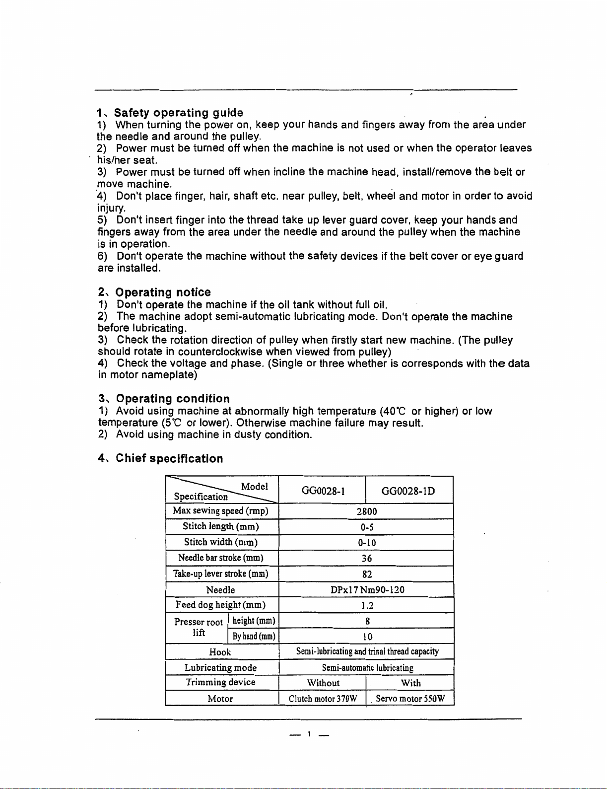
4
..
Chief specification
p
~
Max
Needle
Take-up
Feed dog height (mm)
Presser root
sewing
speed
(rmp)
Stitch length (mm)
Stitch width (mm)
bar
stroke
(mm)
lever
stroke
(mm)
Needle
height
lift
Lubricating mode
Trimming device
Hook
Motor
By
hand
(mm)
(mm)
GG0028-1
2800
0-5
0-10
36
82
DPxl 7 Nm90-120
1.2
8
10
Semi-lubricating
Semi-automatic
Without With
Clutch
motor
- 1 -
and
370W
trinal
lubricating
Servo
GG0028-1D
thread
capacity
motor
550W
Page 5
5, Power cable
1)
When con_necting the power cable to control box, it should confirm the connector
type and machine direction firstly and then plug
completely.
2) Rotary direction: Please refer the instruction
change the rotary direction
connection
of
motor.
the
connector into proper receptacle
book
-of
confected motor if it needs
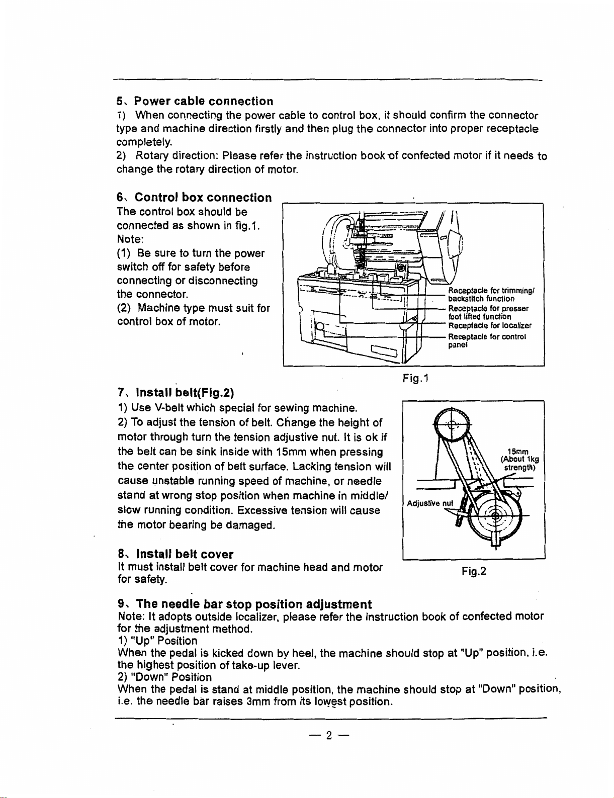
6, Control box connection
The control box should be
connected as shown in fig.1.
Note:
(1) Be sure to turn the power
switch off for safety before
connecting or disconnecting
the connector.
(2) Machine type
control box
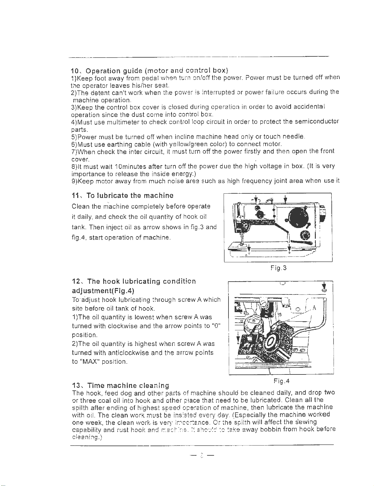
7,
Install belt(Fig.2)
1)
Use
of
V-belt which special
2) To adjust the tension
motor
the
the center posit~on
cause unstable running speed
stand
slow
the motor bearing be damaged.
through turn the tension adjustive nut.
belt
can be sink inside with 15mm when pressing
at
wrong stop position when machine in
running condition. Excessive tension will
must
motor.
of
suit for
for
sewing machine.
of
belt. Change the
belt surface. Lacking tension will
of
machine, or needle
L....-----,.w::...,-1-+--
"-~-------1,-+--1~-
height
It
·~-....,_..,.__
L...------~---
Fig.1
of
is
ok
if
middle/
cause
Receptacle for trimming/
backstitch function
Receptacle for presser
foot lifted function
Receptacle for localizer
Receptacle for control
panel
to
8,
Install belt cover
It
must
install
for
safety.
9,
The needle bar stop position adjustment
Note:
for
1)
When the pedal is kicked down by heel, the
the highest position
2) "Down" Position
When the pedal is stand at middle position, the
i.e.
It
the
adjustment method.
"Up"
Position
the
needle bar raises 3mm from its low~st position.
belt
cover for machine head and
adopts outside localizer, please refer
of
take-up lever.
motor
the
machine
machine
-2-
instruction book
should stop
should stop
Fig.2
of
confected motor
at
"Up" position, i.e.
at
"Down"
position,
Page 6
10, Operation
1 )Keep foot away from pedal when tu
the operator leaves his/her seat.
2)The detent can't work when the power is interrupted or power fa ilu
machine operation.
3)Keep the control box cover is closed during operation in order to avoid accidental
operation since the
4)Must use multimeter to check control loop circuit in order to protect the semiconductor
parts .
5)Power must be turned off when incline machine head only
6)Must use earthing cable (with yellow/green color) to connect motor.
?)When check the inter circuit, it must turn
cover.
8)1t
must wait 1 Ominutes after turn
importance to release the inside energy.)
9)Keep motor away from much noise area
guide
dust
(motor
come into control box.
and
control
rn
onto~ the power. Power must be turned off when
off
off
the power due the high voltage in box. (It
$UCh
box}
re
occurs during the
or
touch needle.
the power firstly and then open the front
is
very
as high frequency
joint
area when use it
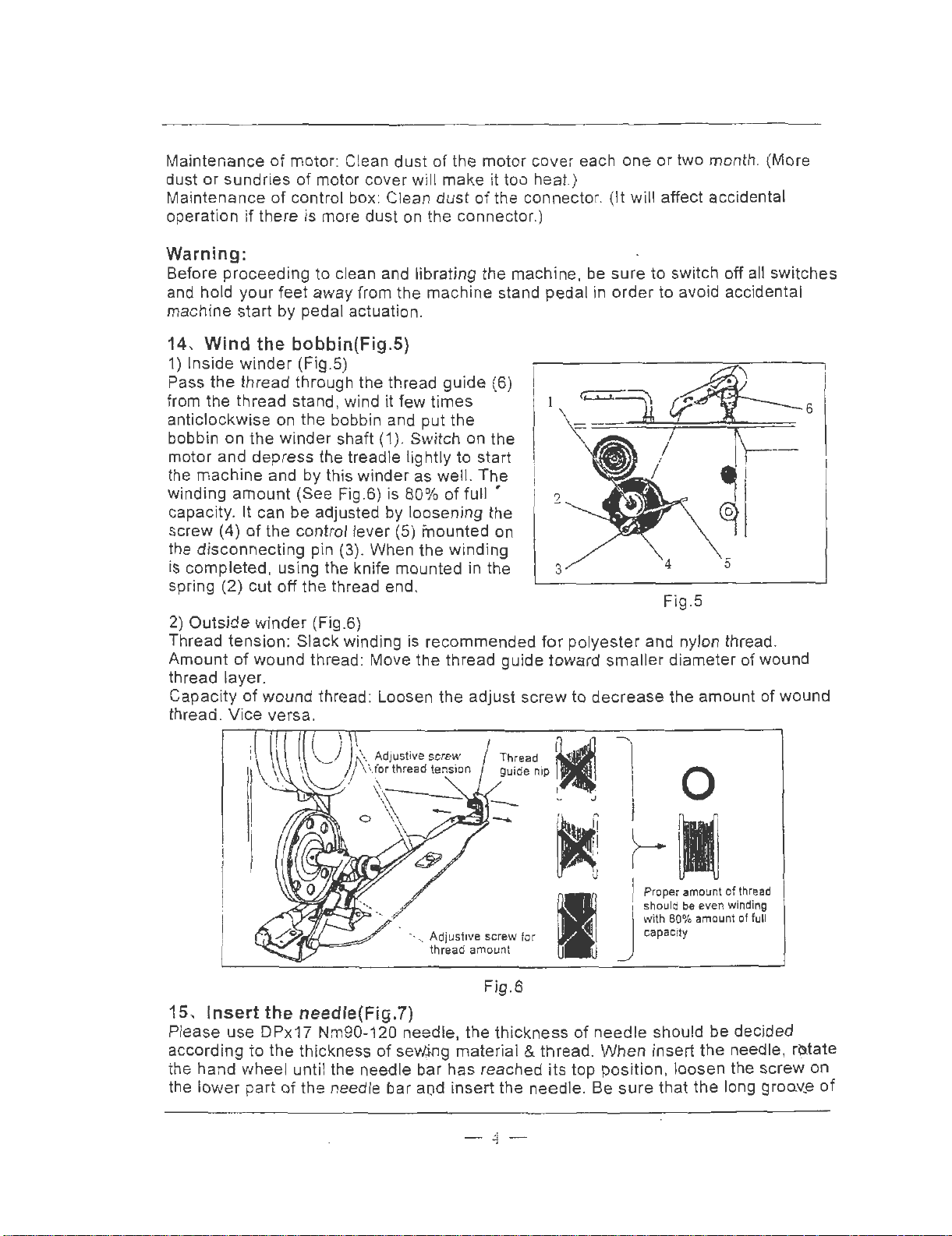
11- To
Clean the m·achine completely before operate
it daily, and check the oil quantity
tank. Then inject oil as arrow shows in fig.3 and
fig.4, start operation
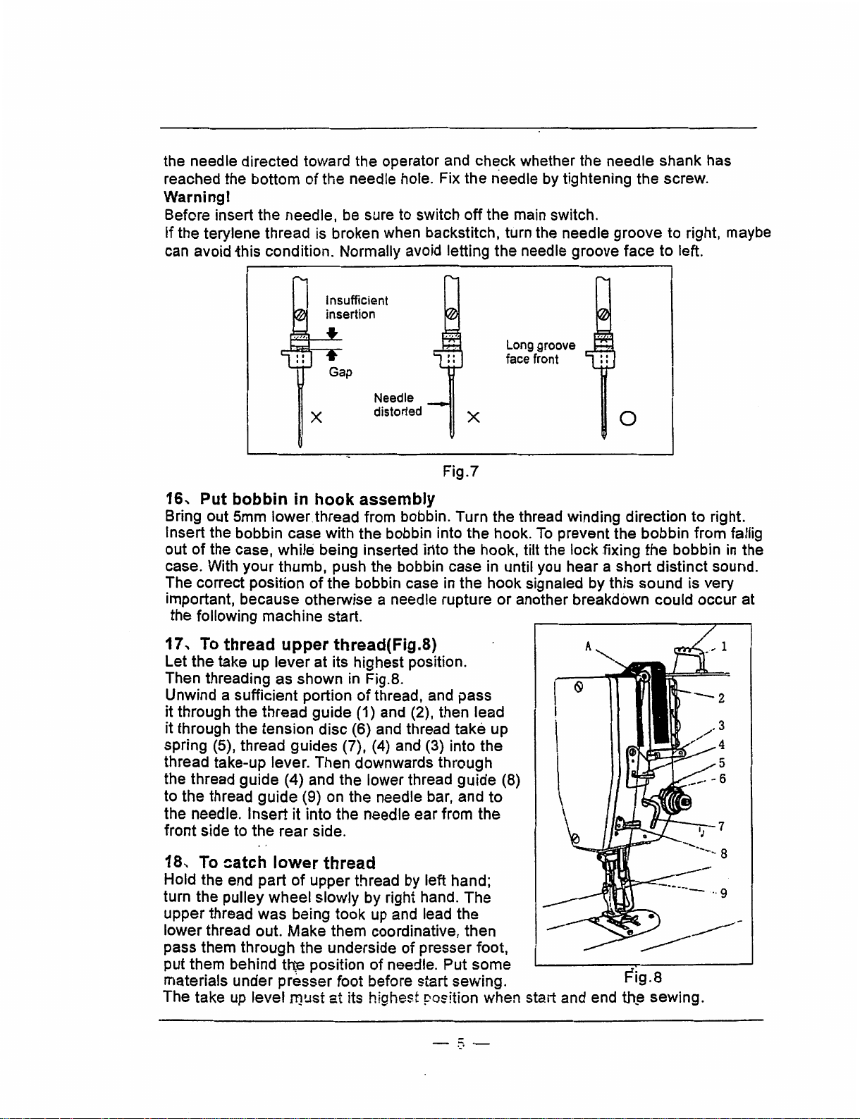
12,
lubricate
the
of
machine
machine.
The hook lubricating
of
hook oil
condition
adjustment(Fig.4)
.To
·adjust hook lubricating !hrough screw A which
tank
of
hook
site before oil
.
1 )The oil quantity is lowest when screw A was
turned with clockwise and the arrow points to "
position.
2)The oil quantity is highest when screw A was
turned with anticlockwise and the arrow points
"MAX"
to
position.
Fig.3
O"
13
,
Time
The
hook, feed dog and
or three coal oil into hook
spilth after ending
with oil. The clean work
one week , the clean work,is very ir.ioc,tance.
capability and rust hook and r.:ae;~:ne. !t sh0u!d
ea
ning.)
cl
machine
of
cleardng
other
parts
of
machine should be cleaned dai
an
d other piace that need to be lubricated. Clean all the
highest speed ope ~ation
must
be ins'.sted every day. (Especially the machine
of
machine, then lubricate
Oi
the spilth will affect
:c
.3
Fig.4
ly,
and drop two
the
machine
worked
the
s'ewing
take away bobbin from hook before
Page 7
Maintenance
dust or sundries
Maintenance
operation
of
motor: Clean dust
of
motor cover will make it too heat.)
of
control box: Clean
if
there is more dust on the connector
of
the motor cover each one or two month . (More
dust
of
the connector. (
.)
Warning:
Before proceeding to clean and librating the machine, be
and hold your feet away from the machine stand pedal in
machine start by pedal actuation.
14,
Wind
1) Insi
the
Pass
the
from
anticlockwise on the bobbin and put
bobbin on the winder shaft (1
motor and depress the treadle lightly
the machine and by this winder as well. The
winding amount (See Fig.6) is 80%
capacit
screw (4)
the disconnecting pin (3). When the winding
is completed, using the knife mounted
spring (2) cut
2) Outside
Thread tension : Slack winding is recommended
Amount
thread
Capacity
thread. Vice versa.
the
bobbin(Fig.5)
de
winder (Fig.5)
thread through the thread guide (6)
thread stand, wind it few times
the
).
Switch on the
to
start
of
full •
y.
It can be adjusted by loosening the
of
the control lever (5) mounted
off
the thread end.
winder
of
wound thread: Move the thread guide toward
layer
.
of
wound thread: Loosen the adjust screw to
(Fig.6)
in
on
the
2
3
for
polyester and nylon thread.
decrease
It
will affect accidental
sure
to switch off a
order
to avo
smaller
id
accidental
5
Fig.5
diameter
the amount
ll
switches
of
wound
of
wound
',
Adjustive
thread amount
15,
In
sert
the
needle(Fig.7)
Please use DPx17 Nm90-120 needle, the thickness
of
according to the thickness
the hand wheel until the needle bar has reached its top position, loosen the screw on
of
the lower part
the needle bar aod insert the needle . Be
sew,i.ng
screw
for
I
Fig.6
material & thread.
-
4-
0
Proper amount
should
80
with
capacity
of
needle should be decided
When
insert the needle, r~tate
sure
that
be
even winding
% amou
the
of
thread
nt
of
long groQv_e
full
of
Page 8
the needle directed toward the operator and ch~ck whether the needle
reached the bottom
of
the needle hole. Fix
the
needle by tightening
the
Warning!
Before insert the needle. be sure to switch
if
the terylene
can avoid -this condition. Normally avoid letting
thread
is broken when backstitch. turn the needle
Needle
X
distorted
off
X
Fig.7
the main switch.
the
needle groove face
Long groove
face front
groove
0
shank
screw.
to
has
to
right. maybe
left.
16, Put bobbin
Bring out 5mm lower. thread from bobbin. Turn
Insert the bobbin case with
out
of
the case,
case. With
The correct position
important,
the following machine start.
17,
To
Let
the
Then threading
Unwind a sufficient portion
it through
it through the
spring (5), thread
thread take-up lever. Then downwards
the thread
the
to
the needle. Insert
front
18,
To
Hold the end
turn the pulley
upper
lower
pass them
put them behind
materials under
The
take up level
your
because
thread upper thread(Fig.8)
take up
the
guide
thread
side to
the
catch lower thread
thread
thread out.
through
in
hook assembly
the
bobbin into
while
being inserted into
thumb, push the bobbin case in until you hear a
of
the
bobbin case in
otherwise a needle rupture
lever
at its highest position.
as
shown in Fig.8.
of
thread, and
thread
tension
guide
part
wheel
was
guide
guides
(4) and the lower thread
(9) on the needle bar,
it
into the needle ear from
rear
side.
of
upper
being took
Make
the
th,'e
position
presser
must
(1) and (2), then lead
disc
(6) and thread
(7), (4) and (3) into
thread by left hand;
slowly
by
right hand.
up
and lead
them coordinative, then
underside
foot before start sewing. F1g.8
at
its highest position when start and end th~
of
presser foot,
of
needle. Put
the
the
the
pass
take
through
guide
and
The
the
some
the
thread winding direction
hook.
hook, tilt the lock .fixing
hook signaled by this
up
the
to
the
To
prevent
or
another breakdown could occur at
(8)
'------..-.
the
bobbin
short
sound
the
bobbin
distinct
_____
sewing.
to
right.
from fallig
in
sound.
is very
the
_.
-::.-
Page 9

19,
The sti
1) The stitch length can be adjusted by turning
of
the machine arm, from O
in
crease
2)
Depress the backstitch hand lever (
3) Depress the
tch
length
the
stitch length. By turning it in the
backst
and
backstit
to
5mm. By turning it in
itch button
as
ch
adjustment
1)
can
shown in
(Fig
.9iFig.10)
the
knob (4) provided on the
the
sense
proceed
Fig.10
of
sense
the arrow "B", you d_ecrease it.
backstitch.
can proceed backstitch.
of
column
the arrow "A",
Ba
ckstitch
button
you
Fig.9
20,
The
stitch width adjustm
Before
outside
ad
increa
locking spanner (2) afte r
21
The
in
(Fig.12)
1) To
lower
clo
decrease
2) To
screw A in Fig.14.
3)
tension for special
adjustment
the
sewn work. Release the locking
just sti
,
terrel
ckwise
It can adjust
tch width
se
the
The
thread tension ad justm
tension
ated that
adjust
thread
to
it.
adjust
of
the stitch width, the machi ne
through
zigzag stitch width. By displacing it
of
upper
the
tension. Turn
increase
the
and
the
stitch forming and l:he sewn m
upper
lower
the
thread tension according
the tension, or inversely, to
threa
take
sewn
ent
(Fig.9)
the
spanner (3). By
the
adju~tment is well.
ent
(Fig.11 ,
the
lower thread
the
tension adjustive
d tension by turning
up spring to adjust
material and thread.
must
X
spanner
displacing
to
12,
be
ateria
to
nut
adjust
upper
thread
Fig.10
must
be stopped and the
(2) (anticlockwise) and
the
lever to the right can
the left
can decrease i
14)
l.
the
in
ive
Tension
adjustive
X
needle
then
t. Lock the
Tighten
nut
Fig
.11
Balance tem;i
or-
Tight upper thread tension Tight lower thread tension
::r loose lower thread tens
Fig.12
-6
io
n
-
or loose upper thread te.nsion
Page 10
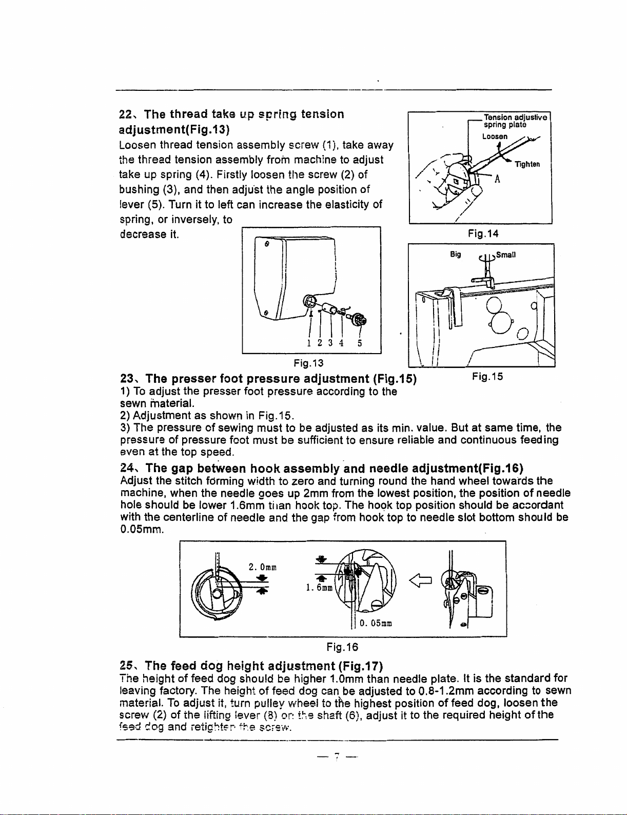
22, The thread take
adjustment(Fig.13}
Loosen thread tension assembly screw
the thread tension assembly from machine to adjust
take up spring
bushing (3), and then adju·st the angle position
lever (5). Turn it to left can increase the elasticity of
spring, or inversely, to
decrease it.
(4). Firstly loosen
up
sprfng
tl1e
&
tension
{1
),
screw (2)
I
take away
of
of
Big
Tension
spring
Fig.14
adjustive
plate
~mr~
1 2 3 4 5
Fig.13
23, The
1)
To
sewn material.
2) Adjustment as shown in Fig.15.
3) The pressure
pressure
even
24, The gap between
Adjust the stitch forming width to zero and turning round the hand wheel towards the
machine, when the needle goes up 2mm from the lowest position, the position
hole should be lower 1.6mm
with
0.05mm.
presser
adjust the presser foot pressure according to the
of
pressure foot
at the top speed.
the
centerline
foot
pressure
of
sewing
. .
must
must
hook
ti
of
needle and the gap from hook top to needle slot bottom should be
adjustment {Fig.15)
to be adjusted as its min. value. But at same time, the
be sufficient to ensure reliable and continuous feeding
assembly
1an
hook top. The
and needle adjustment(Fig.16)
hoc;>k
top position should be ac::ordant
Fig.15
of
needle
I
0.
05mm
Fig.16
25, The feed
The height
leaving factory. The height
material.
screw (2)
fs9d cog and ietight~r·
To
dog
height
of
feed dog should be higher 1.0mm than needle plate. It is the standard for
adjust it, turn pulley wheel to the highest position
of
the lifting lever (8) or:
adjustment
of
f-r:e
scrsvi:.
(Fig.17)
feed dog can be adjusted to 0.8-1.2mm according
t~:s
shaft
(6), adjust it to the required height
- 7
-·
of
feed dog, loosen
of
to
the
sewn
the
Page 11
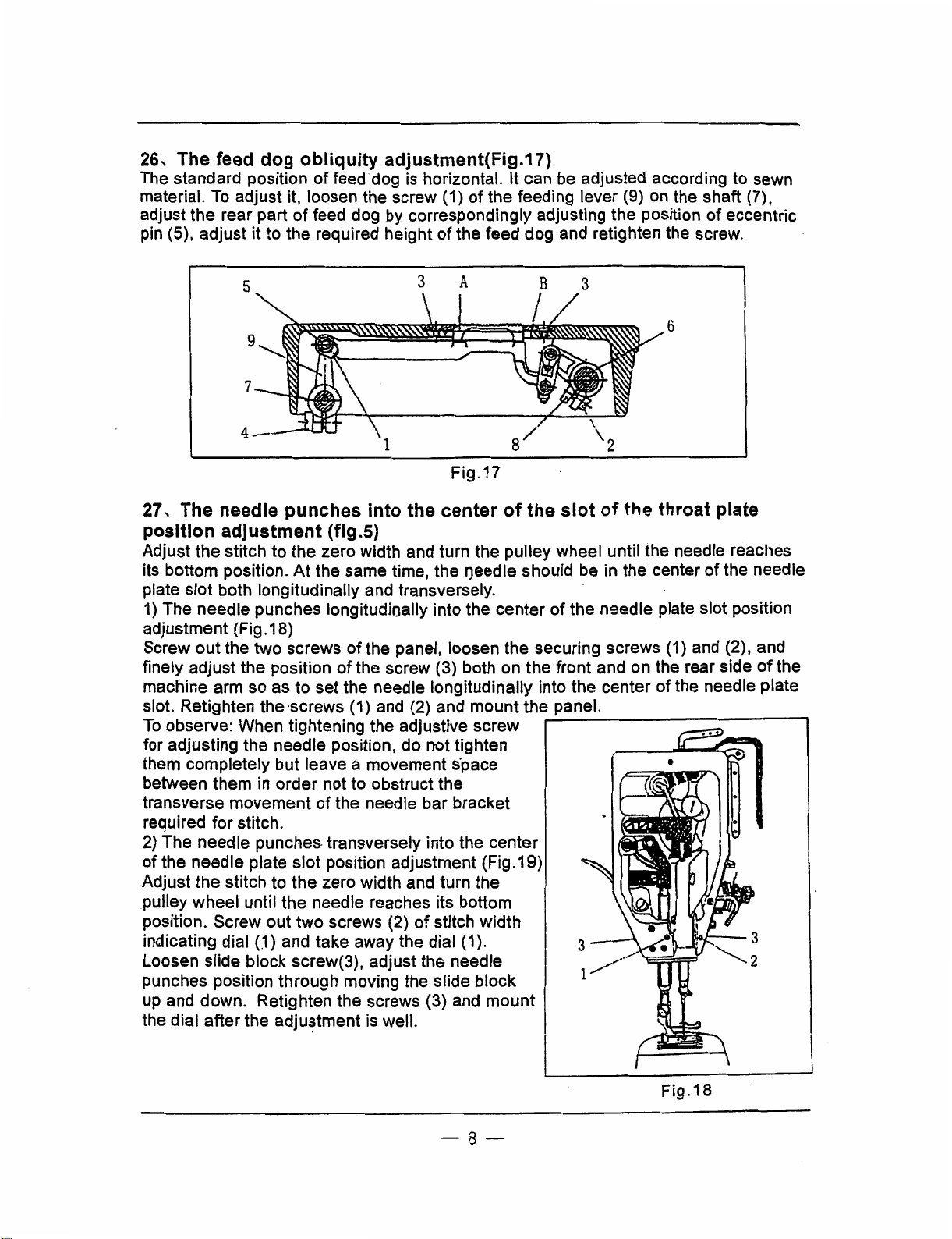
26, The feed
The standard position
material.
adjust the rear part
pin
To
(5), adjust it to the required height
dog
obliquity
of
feed dog is horizontal. It can
adjust it, loosen the screw (1) of the feeding lever (9) on the shaft (7),
of
feed dog
adjustment(Fig.17)
be
adjusted according to sewn
by
correspondingly adjusting the position of eccentric
of
the feed dog and retighten the screw.
6
Fig.17
27, The needle punches into the center of the slot of the throat plate
position adjustment (fig.5)
Adjust the stitch to the zero width and turn the pulley wheel until the needle reaches
its bottom position.
plate slot both longitudinally and transversely.
1)
The needle punches longitudinally into the center
adjustment (Fig .18)
Screw out the two screws of the panel, loosen the securing screws
finely adjust the position
machine arm so as to set the needle longitudinally into the center of the needle plate
slot. Retighten the ·screws (1) and (2) and mount the panel.
To
observe: When tightening the adjustive screw
for adjusting the needle position, do not tighten
them completely but leave a movement
between them
transverse movement
required for stitch.
2)
The needle punches transversely into the center
of the needle plate slot position adjustment (Fig.19)
Adjust
pulley wheel until the needle reaches its bottom
position. Screw out two screws (2)
indicating dial
Loosen slide block screw(3), adjust the needle
punches position through moving the slide block
up
the dial after the adju~tment
the
stitch to the zero width and turn the
and down. Retighten the screws (3) and mount
At
the same time, the f)eedle should be
of
the screw (3) both on the ·front and on the rear side
in
order not to obstruct the
of
the needle bar bracket
of
(.1)
and take away the dial (1).
is
well.
s·pace
stitch width
in
the center of the needle
of
the n9edle plate slot position
(1)
and (2), and
-------------,
of
the
-8-
Fig.18
Page 12
5
4
0
5
Fig.19
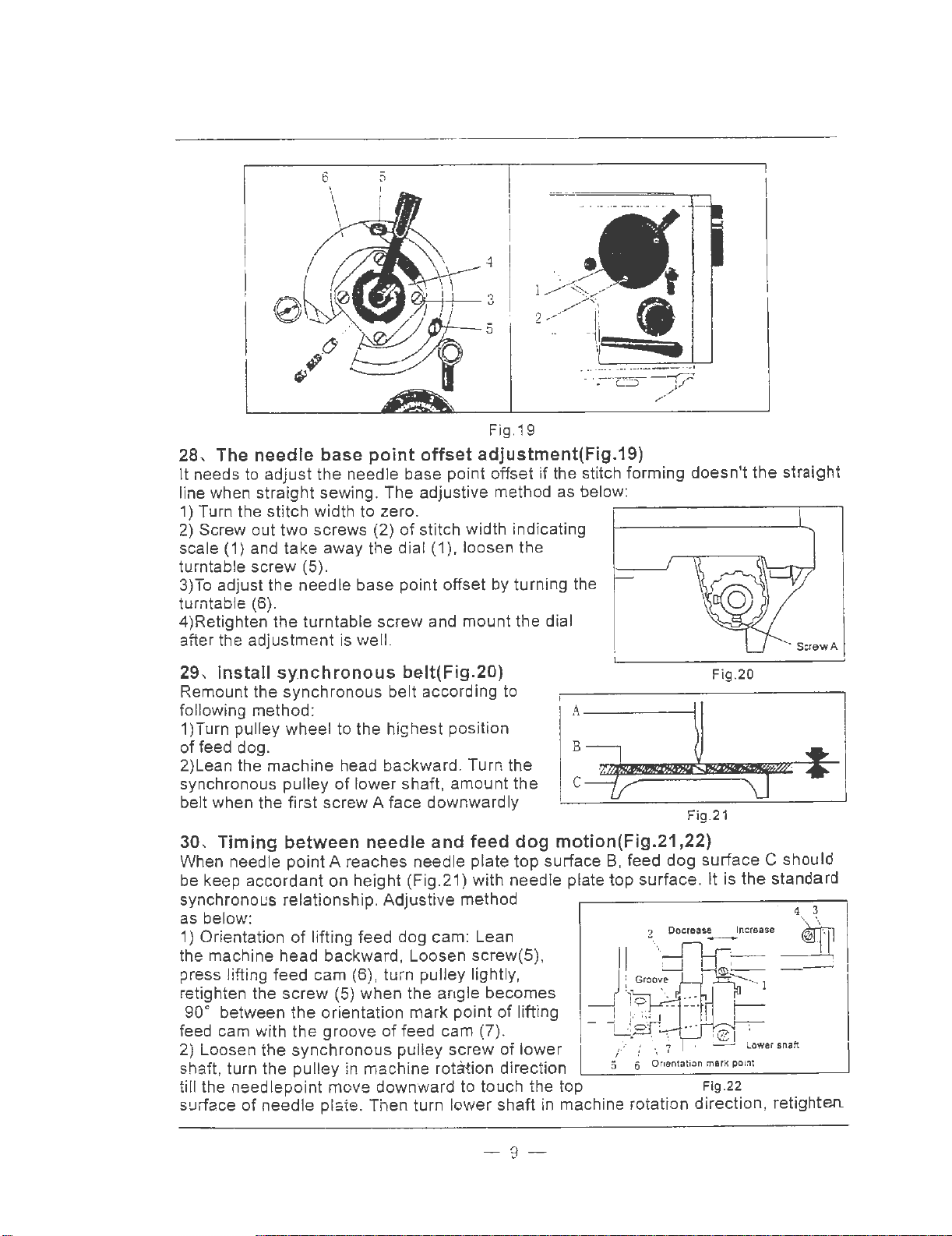
28
, The needle base point offset adjustment(Fig.19)
It needs to adjust the needle base point offs
sew
line when straigh t
ing. The adjust ive method as below:
et
if the stitch forming doesn't
1) Turn the stitch width to zero .
2) Screw out
(1
scale
two screws (2)
of
stitch width indicating
) and take away the di al (1), loosen the
turntable screw (5).
3)
To
adjust the needl
e base point offset by turn i
ng
the
turntable (6).
Re
4)
tighten
the
turntable screw and mount the dial
after the adjustment is well.
29, Install sy.nchronous belt(Fig.20)
Remount the synchronous belt acco rding to
ng
followi
method:
1 )Turn pulley wheel to the highest posi tion
of
feed dog.
2)Lean the
synchronous pulley
machine
head backward. Turn the
of
lower shaft, amount t
belt when the first screw A face downwardly
he
A-
B
C
---
----
-----~
~
Fig.21
F
ig.20
the
straight
-
----..
30, Timing between needle and feed dog motion(Fig.21 ,22)
When needle point A reaches needle plate top surface B, feed dog surface C should
be keep acco
on height (Fig.21)
wit
h needle plate top surface. It is the stand
rd
ant
synchronous relationship. Adjustive method
be
low:
as
1)
Orientation
the machine head backward, Loosen
press lifting feed cam (6) , turn pulley lightl
re
tighten the
90
° between
feed cam with
2) Loosen the synchronous pulley screw
shaft, turn
ti
ll the need
surface
of
of
lifting feed dog cam: Lean
sc
screw
the
lepoint
(5) whe n the angle becomes
the
orientation mark point
the
groove
pulley
of
feed cam (7).
in
machine rotation
move down ward to tou
needle piste. Then turn lower
-
rew(5),
y,
of
lifting
of
lower
direc
tion
ch
the top Fi
shaf
t in machine rotation direction, retighten.
9-
g.2
2
Lower
ard
shaft
Page 13
the synchronous pulley screw when feed dog surface keep accordant on height with
needle plate top surface.
31, The
forward/backward
stitch
length
error
adjustment(Fig.22)
1 )Adjust the forward/backward stitch length error through
to adjust the position
of
the
backstitch block on backstitch connection shaft.
2)Lean the machine head backward, loosen backstitch
(1
).
At
block screw
same time, press backstitch pin (3)
backstitch connection shaft (2) in order to avoid
it
of
fall off
5
backstitch control lever crank (4).
3)Backstitch length will be increased when remove
backstitch block to right, and it will be decreased
when
remove backstitch block to left.
4)Retighten backstitch block screw
(1) after the
4-
3
-~21H!~jil--.---lll-
2
---b~~~
_:__..,uj,,..h,
adjustment is well.
Fig.23
32, The position between hook and opener motion adjustment(Fig.23)
1)Lean the machine head backward, screw out
saddle, open bottom cover
2)Put the needle bar
to
3)Loosen thread finger cam screw
site on the nearest position
4)Loosen hook
opener
(2).
its lowest position.
(3), adjust thread finger cam
of
hook, and then retighten thread finger cam screw.
screw (5), adjust the distance between thread finger and hook
the
bottom cover screw (1)
(4)~
of
hook
make thread
finger
is 0.3-0.4mm.
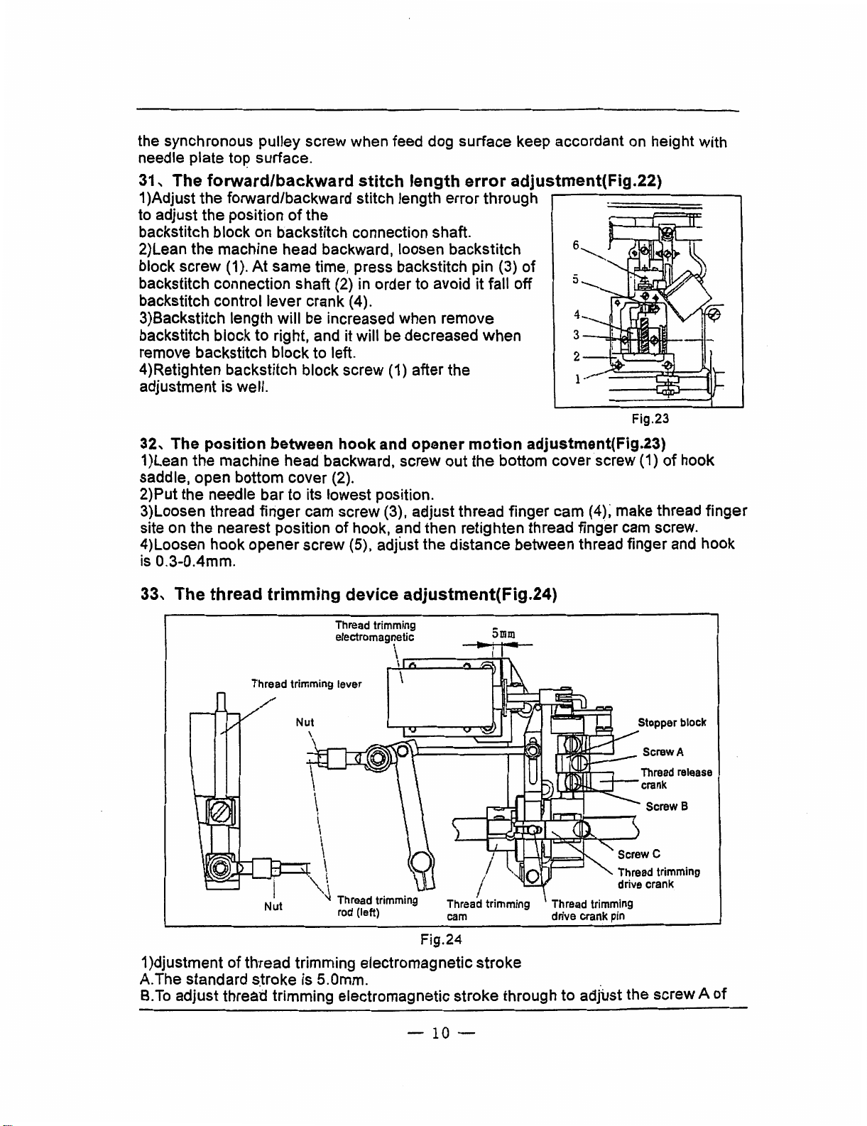
33, The thread trimming device adjustment(Fig.24)
Thread trimming
electromagnetic
Thread trimming lever
Nut
\
\
\.-----._...M.
\
5mm
\
\
\
\
\
. \
~\
~
Nut
Thread trimming
rod
(left)
Fig.24
Thread trimming
drive crank pin
1 )djustment of thread trimming electromagnetic stroke
A.The standard stroke is 5.0mm.
B.To
adjust thread trimming electromagnetic stroke through to adjust the screw A
Thread trimming
drive crank
Stopper block
Screw A
Thread
release
crank
Screw
B
of
-10-
Page 14

stopper block.
2)Adjustment
A.
Turn pulley till the needle to its lowest position.
B.
Press the thread trimming drive crank, put the thread trimming drive crank pin into
of
thread trimming cam
groove of thread trimming cam.
C.
Turn pulley, adjust thread trimming cam till the movable knife start to move and the
take up lever start to lift from its lowest position.
3)Adjustment
cam
(Fig.25)
A.
Turn pulley till the needle to its lowest
of
gap between thread trimming drive crank pin and thre~d trimming
po.sition.
B.
Loosen screw C of thread trimming
drive crank, put the thread trimming drive
crank
pin into groove
C.
Adjust the distance between the
surface
of
pin with the bottom
cam
groove is 0.5mm, retighten screwC
of
thread trimming cam.
thread trimming drive crank
of
thread trimming
of Thread trimming drive crank.
4)Adjustment
A.
Loosen two nuts
of
movable knife position (Fig.26)
of
thread trimming rod
(left). .
B.
To
·adjust the thread trimming rod (left),
......,.,.-·......_.~
1
0.5mm
' ScrewO
Thread
drive
crank
Screw
C
Fig.25
Thread trimming ·
pressure
~
trimming
-$-
Screw 8 release
adjustive
nut
Thread
0-0.
make the distance between the acclivitous
forepart surface
forepart
of
retighten nut.
of
movable knife.with the
fixed knife is 0-0.Smm, then
Slide plate Movable knife Fixed knife
crank
5mm
Fig.26
5)Adjustment
A.
Turn the thread trimming pressure adjustive
of
pressure
of
movable knife and fixed knife (Fig.26)
nut
of slide plate to adjust the mesh
power
of
movable knife and fixed knife.
B.
To
confirm the thread trimming whether is sharp by moving the movable knife after
ending adjustment. .
To
observe: The more mesh power will bring large operation moment and failure
trimming, so it should to be adjusted to its minimum.
6)Adjustment
A.
Turn pulley till the needle to its lowest position.
B
..
Press the thread trimming drive crank, put the thread trimming drive crank pin into
of
releasing gap
of
thread tension disc (Fig.25)
groove of thread trimming cam.
C.
Turn pulley till the take
up
lever to its lowest position. Here the releasing gap
tension disc should be its maximal.
D.
The ringent degree can
shaft connection. During adjustment, loosen the screw D
and shrink the flexible
~e
wire.-.
adjusted through thread release crank and
of
release soft-shaft connection
rel(:3.ase
- 11 -
of
thread
soft-
Page 15

A,
Arm
29
bed
and its
accessories
'
28
21
(20)
26
(2)--__;~~~~~
25
(12)~
23~
24-
22----
··
....
·
,··...
~--
··~
... ~ ..
_,
'•,
,:-::
..
,,::~---·····
..........
. .
········...
· . •
· ·
•.
<e,(J)·~ . ·.
··.~~
,,r~.::~~-
~~
_ .
.,
~-·~
·
..
_·. · ..
......
.
~
·.
'"
·
...
-.
··
...
•:-~-~
·
...
~~.
- 12 -
Page 16

A,
Arm
bed
and
its
accessories
No.
A0l
A02
A03 7.02.16.-058
A04
A0S 7.02.11.060
A06
A07
A08
A09 7.02.14.032
AI0
All
Al2
Al3
Al4
Al5
Al6
A17
Al8
Al9
A20
A21
A22
A23
A24
A25
A26
A27
A28
A29
A30
PartNo.
7.02.11.059
7.02.15.388
7 .02.16.032
~-~
7.02.16.078
7.02.14.031
7.02. 15.393
7.02.11.063
7.02.15.006
7.02.15.391
7 .02.14.029
7.02.15.392
7.02.18.070
7 .02.14.028
7.02.14.027
7.02.14.025
7 .02.15 .390
7.02.14.026
7.02.01.044
7.02.10.088
7.02.01.038
7.02.02.085
7.02.02.086
7.02.11.062
7.02.15.389
7.02.l 1.061
7.01.02.013
--
Name
up
Thread take
Thread take
plug
Plastic
Felt
Top
cover
Aluminium oil spite
Nut
Thread guide lever(upper)
Winder
cover
Round
cover
Round
Winder fixed screw
guide
Thread
Thread guide lever (middle)
guide
Thread
washer
Screw
guide
Thread
Thread guide plate
Thread guide lever(lower)
Lower thread guide platcfscrew
Lower
thread
Winder assy.
Release
Thread tension assy.
Slide plate
Needle plate
Felt splint
screw
Panel
Panel
Machine frame
lever guard cover
up
lever guard cover screw
thread
clip small assy.
screw
lever (middle) screw
plate screw
plate
guide plate
pin
Qty.
GG0028-I
1 1
12
5
1 I
1 1
I
1
1 1
1
I I
I 1
3
I
1
1 1
1
1
1 1
1 1
3 3
1
1 1
1 I
1 I
1
1 I
1
2 2
1
1 I
GG0028-1D
10
4
l
1
1
3
1
1
~
1
1
1
l
Remark
M4X8
JII.
M3X12
M4X8
M4X5
M3X6
GB/T97.1 3
M3X8
M5X14
-#;
A07
to
...__...._
____
be ordered
---,1~--------------'---···---'----------
with
A08
-13-
Page 17

B,
Arm
shaft
and
needle
bar
thread
33
take
35
up
36 37
parts
38
11
12
13----.J
14----lil-.A
l
6------11
44 45
-
14-
46
17
49
(32)
50
51
Page 18

B.
I
!
l
Arm
No.
BO!
B02
B03
B04
B05
B06
B07
B08
B09
BIO
B11
B12
B13
B14
B15
B16
B17
B18
B19
B20
B21
B22
B23
B24
B25
B26
B27
B28
B29
B30
B31
B32
B33
B34
B35
B36
33,
shaft
PartNo.
7.02.10.091
7.02.15.411
7.02.05.066
7 .02.06.036
7 .02.04.025
• 7.02.05.067
7.02.15.395
7.02.15.413
7.02.15.408
7.02.02.088
7.02.03.071
7.02.15.409
7 .02. l O .090
7.02.15.412
7.02.14.030
7.02.21.140
7.02.16.219
~
~~
~-
7.02.05.065
7 .02.15 .056
7.02.15.400
7.02.15.401
7.02.15.037
7.02.15.404
7.02.15.403
7.02.10.089
7.02.05.064
7.02.15.396
7.02.15.397
7.02.16.035
7.02. 15.398
7.02.16.090
7.02.15.399
7.02.04.024
7.02.08.095
7.02.07.059
7.02.17.094
7.02.09.032
and
Thread
Thread
Thread
Libra
Bearing
Needle
Libra
Thread
Needle
Needle
Needle
Needle
Needle
Screw
Needle
Needle
Needle
Needle
Needle
Needle
Needle
Needle
Needle
Needle
Needle
Needle
Tighten
Needle
Needle
Needle
Felt
Arm
Arm
Arm
Winder
Replacement
\\-:nder
needle
take
up
take
up
take
up
crank
bar
link
crank
screw
take
up
bar
joint
bar
joint
bar
clamp
clamp
clamp
bar
joint
bar
connection
bar
connection
bar
connecti9n
bar
connection
bar
connection
bar
connection
bar
connection
bar
connection
bar
connection
screw
bar
crank
bar
crank
bar
crank
shaft
bushing
shaft
bearing
shaft
bushing
drive
spring
drive
bar
lever
lever
lever
rod
crank
screw
shaft
shaft
washer
oil
tighten
orientation
pulley
pulley.
thread
Name
support
support
assy.
screw
screw
wick
holder
bracket
bracket
bracket
bracket
bracket
bracket
bracket
bracket
screw
epllar
screw
screw
stud
stud
tighten
screw
screw
shaft
screw
screw
shaft
take
screw
(back)
(left)
screw
(front)
(right)
screw
up
parts
GG0028-l
I
I
I
I
2
I
I
1
I
1
1
1
I
I
1
1
1
1
I
1
I
1
I
1
1
1
1
1
I
1
I
I
2
I
I
I
1
Qty.
GG0028-1D
1
1
1
I
2
1
1
l
I
I
I
I
1
1
I
I
1
1
I
l
1
l
1
1
1
I
I
1
I
I
I
1
2
1
1
I
I
Remark
M6(0.75)X8
HK.0810
M6(0.75)X7.5
9/64(40)X
M4X8
M2.SX5
M3X5.8
19•
!l>2X25mm
M5X5
M4Xl2
M6(0.7S)X30
M3X6
M4Xl6
M6(0.
MSXJO
M6(0.7S)X
M6(0.75)X
M6Xl4
6003
5.S(left)
75) X 11
15
17.5
-15-
Page 19

B,
Arm shaft and needle bar thread take up parts
No.
B38
B39
B40
B41
B42
B43
B44 7.02.07.053
B45
B46
B47
B48
B49
BSO
BSl
PartNo.
7.02.15.407
7.02.15.428
7 .02.08.102
7.02.07.051
7.02.15.126
7.02.03.070
7.02.15.431
7 .02.18.076
7.02.18.078
7 .02.04.027
7.02.07.054
7 .02.11.064
7.02.15.432
Name
Drive pulley orientation screw
Collar screw
Arm
shaft bearing collar
Vibrating needle drive gear
Small gear screw
Arm shaft
Synchronous pulley (upper)
Synchronous pulley screw 2
Elasticity stop
Elasticity stop ring
Arm shaft bearing(right) 1 1
Pulley
Pulley cover 1 1
Pulley cover
ring
screw
Qty.
GG0028-l
1
3
1
1
3
1
1
1 1
1
1 l
3
GG0028-1D
~
3
I
1
3
1
1
~
1
3
Remark
M6(0.75)X7
M6(0.75)XS
l/4(40)X7
M6(0.7S)X
10
GB/T893.1-1986-62
GB/T894.l-1986-30
6206
M3X8
'
-16-
Page 20

C,
Needle
1 2 3
\J~
4----f
bar
vibrating parts
26
27
I I
28
fl
I I
;J---30
&J--31
10
1!-·
--·12
-.
17 -
Page 21

C,
Needle bar vibrating parts
No.
COI
CO2
Co3
C04
cos
C06
C07
cos
C09
ClO
Cll
C12
C13
Cl4
ClS
C16
Cl7
C18
C19
C20
C21
C22
C23
C24
C25
C26 7.02.06.037
C27
C28
C29
C30 · 7.02.03.074
C31
C32 7.02.08.100
C33
C34 7.02.15.426
C35
C36 7.02.15.449
j
C37
PartNo.
7.02.15.405
7.02.18.071
7.02.13.043
7.02.01.039
1.02.15.407
7.02.15.391
7.02.15.406
7.02.08.096
7.02.15.410
7 .02.08.097
7.02.08.101
7.02.17.091
7.02.15.443
7.02.16.219
7.02.15.049
7 .02.03.075
7 .02. l 6.059
7.02.10.093
7.02.05.076
7.02.15.428
7.02.09.030
7.02.16.067
7.02.04.026
7 .02.16.064
7 .02.07 .050
7.02.18.075
7.02.05.077
7.02.16.056
7 .02.08 .099
7.02.15.427
7.02.15.446
7.02.16.0S6
Fixed
bracket
Washer
Needle
bar
Needle
bar
Needle
bar
Tighten
screw
Tighten
screw
Needle
bar
Needle
bar
Needle
bar
Connection
Connection
·
Connection
Felt
Needle
feeding
Needle
feeding
Oil
spile
Connection
Link
lever
·Collar
screw
Needle
feeding
Coppery
Bearing
Aluminium
Vibrating
Vibrating
Coppery
Vibrating
Felt
Vibrating
Vibrating
Connection
Connection
Vibrating
Vibrating
Vibrating
Vibrating
screw
vibrating
vibrating
vibrating
vibrating
vibrating
vibrating
bushing
plate
screw
shaft
oil
spile
oil
needle
needle
washer
needle
range
bushing
bushing
bushing
needle
needle
needle
needle
Name
bracket
crank
crank
crank
plug
driven
cam
link
shaft
screw
eccentric
link
rod
link
rod
eccentric
fixed
bracket
shaft
bushing
shaft
bushing
shaft
bushing
shaft
shaft
shaft
gear
lever
shaft
screw
screw
shaft
bracket
screw
tighten
collar
screw
locklMg
o-ring
(left)
screw
(right)
screw
nut
(small)
Qty.
GG0028-l
5
2
l
1
2
1
1
1
2
1
2
2
2
1
1
1
2
1
1
2
1
1
1
1
1
1
1
1
1
1
1
1
1
1
1
2
I
GG0028-1D
s
2
1
1
2
1
1
1
2
1
2
2
~
1
1
1
2
1
1
2
1
1
1
1
1
1
1
1
1
1
1
1
1
1
1
2
1
Remark
M4X14
GB/T97.1
M6(0.75)X7
M4X5
M3X4
M6X8
MS(O.S)X
MSXB
M6(0.7S)X5
51101
M2X4
M6Xl2
M6(0.75)X34
M6(0.75)
4
14
-18-
Page 22

C,
Needle
bar
vibrating
parts
No.
C38
C39
C40
C41
C42
C43
C44
C45
C46
C47
C48
C49
cso
CSl
C52
C53
C54
css
C56
C57
C58
C59
C60
C61
C62
C63
C64
C65
C66
C67
PartNo.
7.02.16.219
--~---
7 .02. l 0.094
7 .02.16.066
7.02.01.04102
7.02.01.04103
7.02.01.04104
7.02.01.04105
7.02.01.04106
7.02.01.04107
7.02.15.425
7.02.01.04101
7.02.13.044
7.02. 15.416
7.02.18.016
7.02.13.045
7.02.i7.089
7 .02.16 .063
7.02.17.090
7.02.15.423
7.02.12.046
7.02.15.424
7.02.15.451
7.02.15.450
7 .02.04.036
-
7.02.05.071
7.02.15.421
7.02.05.070
7.02.15.417
7.02.16.062
7.02.15.422
Name
Oil wick
Vibrating needle eccentric shaft
0-ring
(big)
Vibrating needle bracket connector
Vibrating needle bracket nut
Vibrating needle bracket holder
Nut
Vibrating needle locking spanner
Vibrating needle locking spanner screw
Vibrating needle bracket link rod screw
vibrating needle bracket link rod
Vibrating bracket
Vibrating range shaft screw
Vibrating range shaft screw washer
Turntable
Vibrating needle spanner stop block
Plug
Plug spring
Plug spring screw
Slide block
Slide block screw
nut
Round
Hexagonal
Vibrating needle spanner orientation pin
Vibrating needle spanner
Vibrating needle spanner handel screw
Vibrating needle spanner handle
Vibrating needle spanner screw
Scale
Scale screw
nut
GG0028-l
1
1
l
1
1
1
1
1
1
1
1
1
1
1
1
1
I
1
1
1
5
1
1 1
1
1
2
1
1
1 1
2
Qty.
GG0028-1D
1
1
1
1
1
1
1
1
1
1
1
I
1
1
1
1
1
1
1 M8(0.75)XS
1
5
1
1
1
2
1
1
2
Remark
Cl>2X80mm
'
M5X12
GBff97.l
M4Xl2
M4X12
M4Xl8
I
I
I
I
I
5
-19-
-
Page 23

D'
Presser foot parts
1----------s
26
32
\
33
(9)
20
Page 24

D,
Presser
foot
parts
I
No.
D01
D02
D03
D04
D05
D06
D07
D08
D09
D10
D11
D12
D13
D14
D15
D16
D17
D18
D19
D20
D21
D22
D23
D24
D25
D26
D27
D28
D29
D30
D31
D32
D""
~~
D34
D35
D36
D37
PartNo.
7.02.15.414
7.02.15.415
7.02.17.085
7.02.18.072
7.02.10.092
7.02.16.033
7 .02.12.045
7.02.1S.417
7 .02.18.031
7 .02.17 .087
7.02.05.068
7.02.15.418
7.02.08.098
7.02.15.411
7.02.03.072
7.02.18.0S7
7.02.15.419
7.02.02.089
7.02.17.088
7.02.15.394
7.02.05.063
7 .02.03.073
7 .02.17 .086
7.02.18.060
7 .02.08.040
7.02.19.035
7.02.15.053
7 .02.11.09S
7.02.15.105
7.02.06.081
7.02.15.048
7.02.10.146
7.02.12.081
7.02.18.016
7.02.15.068
·.7.02.15.416
, J.02.05.069
Presser
Presser
Presser
E·ring
Presser
Felt
·-
Presser
Presser
E·ring
Presser
Presser
Presser
Presser
Presser
Presser
Presser
Presser
Presser
~
Spring
Release
Release
Presser
Replacement.
Washer
Presser
presser
Fixed
Lifting
Lifting
Presser
Presser
Presser
Slide
Washer
Presser
Knee
Knee
foot
bar
bar
bar
bar
bar
foot
bar
bar
bar
bar
bar
foot
foot
foot
lever
lever
foot
foot
foot
plate
presser
presser
foot
foot
foot
pole
foot
lifting
lifting
pressure
sprtng
spring
pin
slide
block
slide
block
lifting
spanner
spanner
bushing
bushing
screw
screw
screw
lifting
spring
lifting
Lifting
screw
foot
foot
lifting
lifting
lifting
lifting
crank
crank
Name
adjustive
support
connection
screw
tighten
washer
sh~ft
.
shaft
electromagnetic
electromagnetic
electromagnetic
crank
crank
crank
crank
screw
screw
screw
screw
bushing
screw
pin
pin
screw
plate
nut
fixed
screw
plate
Qty.
GG0028-l
GG0028-1D
1
1
1
1
1
1
1
1
1
1 1
1
1
1 1
1
1
1
1
1
1
1
1
1
I
1
1
1
1
1
1
1
1
2
1
1
1 M6(0.75)X8
1
1
1
1
1
1
1
1
1
1
1
I
4
1
3 M6X8
1
1 M6X15
1
1
1
1
1 MSX12
I
Remark
GB/T896-l 986·6
M4X12
GB/T896-l 986-4
M3.SX10
GB/T97.1 8
MSX12
GB/T97.l
GB/T6170
5
MS
-21-
Page 25

D,
Presser foot parts
No.
D38
D39
D40
D41
D42
D43
D44
PartNo.
7.02.17.041
7.02.01.04001
7.02.01.04002
7.02.15.420
7.02.01.04003
7.02.01.04004
7.02.01.04005
I
Name
Pin
Presser
:
Link lever fixed plate
foot
lifting link lever
Link h:\er
Link lever collar
Nut
Knee lifting connection nut
f~\.
.. ~ p!!:e screw
Qty.
GG0028-l
1
1
1
3
1
1
1
1
1
GG0028-1D
!
Remark
M4X6
-22-
Page 26

E~
St
itch
length
a
JU
d. stm
ent
d
backstitch
an
parts
---
,~t~
! / i
iL
~?GD~
I /
I i i '
I I I I '
_~
_3
~'r°
_ "
__
56--
;\
, .
~
/
"-9:JtJ
i·
f1
·
I
I
I
- 23 -
! I
71 72 73
Page 27

E,
Stitch length adjustment and backstitch parts
No.
EOl
E02
E03
E04
E05 7.02.12.048 ·
E06 7.02.12.047.04
E07
E08 7 .02.15.428
E09
ElO
Ell
E12 7.02.13.186
El3
E14
El5
El6
El7
EIS
E19
E20
E21
E22
E23
E24
E25
E26
E27
E28
E29
E30
E31
E32
E33
E34
E35
E36
E37
PartNo.
7.02.12.047.01
7.02.12.047.02
7 .02.12.047 .03
7.02.15.006
7.02.16.068
7.02.12.135
7.02.05.217
· 7.02.13.185
7.02.15.017
7.02.16.212
7.02.05.216
7 .02.05.079
7.02.03.077
7 .02.10.078
--~~-
7 .02 .12.049
7 .02.05.078
7.02.05.080
7.02.15.416
7.02.17.092
7 .02.03 .076
7.02.18.021
7.02.12.050
7 .02.15.424
7.02.15.447
7 .02.06.039
7.02.15.436
7 .02.04.024
7.02.01.04201
7.02.01.04202
7.02.01.04203
7.02.01.04204
7.02.05.175
7.02.17.033
Qty.
GG0028-l
Stitch length indication holder nut
Washer
Stitch length indication holder
Stitch length indication holder screw
Stitch length adjustive block
Stitch length indication holder shaft 1
Stitch length indication dial
Stitch length indication dial screw 2
Stitch length adjustive tighten block
Stitch length adjustive lever 1
Stitch length adjustive block 1
Stitch length indication holder 1
Stitch length indication holder screw
Stitch length indication dial
Stitch length dial lbcking screw
Backstitch control lever spanner
Backstitch control lever
Pin
B~ckstitch stop lever block
Stitch length adjustive crank
Backstitch control lever crank 1
-
-Backstitch control lever crank screw
Replacement spring
Backstitch conection shaft
E-ring
Backstitch block
Backstitch block screw
Backstitch block tighten screw
Backstitch cam crank 1
Backstitch cam crank screw 1
Backstitch cam crank bearing 1
Feed
backstitch cam
Feed
backstitch cam bushing
Orientation pin 1
Orientation pin screw
Backstitch link lever
Backs.!itch link lever replacement
spring
2
1
1
2
1
1
1
1
1 1
1
1
2
1
l
1
1
1
1
1
1
I 1
GG0028-10
~
1
2 .
1
1
l
1
1
1
1
2
.
l
1
1
l
3
1
1
1
I
I
1
1
1
1
Remark Name
M4X8
M6(0.75)XS
M4X10
MSX12
GBff896· 1986-7
M4Xl2
M4X6
M5X30
6003
-24-
Page 28

E,
Stitch length adjustment and backstitch parts
No.
E38
E39
E40
E41
E42
E43
E44
E45
E46
E47
E48
E49
E50
E51
E52
E53
E54
ES5
E56
E57
E58
E59
E60
E61
E62
E63
E64
E65
E66
E67
E68
E69
E70
E71
E72
E73
PartNo.
7.02.15.268
7.02.18.031
7.02.10.149
7 .02.06.083
7.02.15.053
7.02.18.055
7 .02.15 .068
7.02.21.176
7 .02.07
.071
7.02.15.107
7.02.15.108
7.02.05.176
7.02.03.112
7.02.10.148
7.02.21.173
7.02.15.1>89
7.02.15.088
7.02.15.106
7.02.10.147
7.02. 19.036
7.02.21.033
7.02.11.104
7.02.18.058
7.02.15.007
7.02.19.030
7.02.19.027
7.02.15.420
7.02.16.166
7.02.15.101
7.02.13.072
7.02. 15.005
7.02.11.079
7.02.01.059
7.02.19.113
7.
02.
I 9 .104
7.02.16.16i
Name
......
Replacement
E-ring
Backstitch
Backstitch
Backstitch link lever
Spring
Backstitch
Knee
Foot
control shaft link
Foot
control shaft
Foot
control
Foot
control shaft link
Foot
control backstitch shaft
Foot
control backstitch
Foot
control backstitch
Stop
screw/nut
Stop
screw
Foot
control shaft nut
Backstitch electromagnetic
Backstitch electromagnetic
Backstitch electromagnetic
Backstitch electromagnetic
Spring
Backstitch electromagnetic
Jacket
Socket
Wire
clip
Nylon
Switch
Switch
Switch
Switch
Backstitch
Earthing
Earfrin~
Nyi:-,
j
spring
link
lever
link lever
washer
link
lever
lifting
Lever
shaft
washer
screw
clip
AB-3N
·
box
fixed
bracket
box
fixed
bracket
box
screw
box cover plate
switch
assy.
wire
plug
c-:ip
ABM8N
nut
assy,
link
link
crank
crank
crank
crank
lever
lever
lever
lever
crank
crank
pin
screw
pin
screw
screw
nut
pin
fixed
fixed
screw
screw
pin
nut
roller
plate
plate
screw
GG0028-l
2
4
l
1
2
1
1
1
t
I
2
l
1
1
1
1
1
1
1
1
4
l
3
3
1
1
3
2
2
1
2
1
I
I
1
1
Qty.
GG0028-1D
-
GBff
GBff896-1986-4
M5X12
GB/T93.
GBff6170
GBff6172
GBfT6172
M6Xl2
MB
GBIT99
GBIT93.
M6X10
M4X6
M3X4
M4X8
Remark
6170
S
MS
MS
M6
Cle)
4.5 X 20
6
M4
-25-
Page 29

F,
Lower
shaft,
feed dog
1 2 3 4 5
\ \ l I
i \ •
\ I I
parts
,1
28
29
~~·
-~~II
30
31
32
(30)
(1)
37
44
-
26-
I
54
Page 30

F"
Lower
shaft,
feed dog
parts
No.
FOi
F02
PartNo.
7.02.16.067
7.02.03.079
F03 7.02.08. 103
F04
7.02.15.428
F05 7.02.15.448
F06
7 .02.05. 081
F07
7.02.15.408
F0S
7.02.08.104
7.02.15.430
f
..
·~
FIO
7.02.06.038
Fll
7.02.15.391
Fl2
7 .02.09
.030
F13
7 .02.08.105
Fl4
7.02.16.072
~
7
.).,
:,:,
7.02.16.219
~~-
-
7.02.10.097
7.02.02.090
7.02.02.087
7.02.15.433
7.02.04.028
7.02.18.079
7.02.18.080
7.02.04.030
7.02.05.082
7.02.16.219
-
~
~
7.02.15.050
7.02.07.055
7.02.16.219
-
-
-
7.02.10.096
7.02.U.082
7.02.04.029
7 . .02.05 .083
7 .02.18.031
7.02.11.065
7.02.10.095
7.02.16.219
~
7 .02.Q~.:080
-
~
FIS
Fl6
Fl
FIS
Fl9
F20
F21
F22
F23
F24
F25
F26
F27
F28
F29
F30
F31
F"'.,
F"'"'
F34
F35
F36
FJ"'
Oil
Feed
Feed
Bushing
Feed
Feed
Feed
Feed
Feed
Feed
Feed
Collar
Feed
Oil
Feed
--
Feed
Feed
~
Feed
Feed
Lifting
Elasticity stop
Washer
Lifting
Lifting
.
Lifting
Lifting
Lifting
Backsti~h
-
Feed
Gear
Backstitch
Backstitch
E-ring
Connection
Lifting
Lifting
Lifting
Name
spile
shaft
shaft
bm:hing (left)
screw
crank (left) screw
crank (left)
dog holder adjustive
shaft
bushing (middle)
crank (right) screw
crank (right)
crank
pin screw
shaft
bushing (right)
spile (big)
dog
holder
adjustive
dog
holder
adjustive
dog holder
dog
dog
screw
feed
dog
cam bearing
riJ?.g
feed
dog
cam link
feed
dog
cam link
feed
dog
cam
feed
dog
cam screw
feed dog cam
cam link lever oil
crank
pin
washer
cam
link lever bearing
cam link lever
plate
feed dog link lever
feed dog link lever
feed dog shaft
pin
screw
pin
oil
pin
lever
bearing
lever
link lever oil
wick
pin
pin
oil
wick
wick
wick
Qty.
GG0028-l
2
1
I
12
1
1
1
I
3
1
4
3
1
1
2
1
GG0028-1D
2
1
1
14
. l
l
1
I
3
1
4 M4X5
4
1
1
2
1
1 I
1 1
2
2
2 2
1
1
1
1
l 1
l
1
1 I <l>2X350mm
2
I
2 M6(0.7S)X8
1
1 1
2
2
2
2
I I
1
4
2
2
1
4
2
2
1 I
I
1
Remark
M6(0.75)X5
M6Xl4
M4X8
M5XI0
<l>2X
M4X6
6002
GB/T894.1-1986-18
<l>2X200mm
GB/T896-1986-4
<l>2X60mm
160mm
-27-
Page 31

F,
Lower
shaft, feed dog parts
No.
F38
F39
F40
F41
F42
F43
F44
F45
F46
F47
F48
F49
FSO
FSl
F52
F53
F54
PartNo.
7.02.08.i08
7.02.05.084
7.02.18.109
7.02.15.389
7 .02.06.040
7.02.16.219
--
~
7.02.03.078
7.02.08.107
7.02.15.058
7.02.06.080
7.02.1S.437
7.02.08
..
106
7.02.04.024
7 .02.18.08
7.02.07.056
7.02.15.431-
7.02.07.052
Name
feed
Lifting
Lifting
Lifting
Lifting
Lifting
Lifting
-
Lower shaft
Lower shaft bearing bushing
Thread trimming
Thread trimming
Lower shaft bearing bushing screw
Lower sbaft bearing bushing 1 1
Lower shaft bearing
l
Synchr9nous pulley (lower) washer 1
Synchronous pulley (lower)
Synchronous pulley
Synchronous belt
dog shaft bushing (left)
feed
dog crank (left)
feed
dog shaft bushing (right)
feed
dog crank (right) screw
feed
dog crank (right)
feed
dog crank pin oil wick
cam
screw
cam
screw
-
GG0028-1
1
1 1
1 1
2
1
l 1
l
1 1
1
I
1 1
2
1
Qty.
GG0028-1D
Remark
1.
2
1
1
2 M5X16
. I
M5X14
<1>2X30mm
1
1
1
1
2
M6(0.75) X 14
6003
M6(0.75)X 10
.
-28-
Page 32

G,
Hook
assembly
1.4
1~
. '
1.6
17
27
I
5
35 36
\ \ 3 ~ 38 39
\ \ \ I /
\
41.
---....___
42
~~~~-
~
·--J----1
~
~
\\
~
-~
~
...._
c.
'
I
\
45
46
\~
//
I
I /
~i
~
i°
;
-
29-
Page 33

G,
Hook assembly
No.
G0l
G02
G03
004
GOS
006
G07
GOS
009
010
011
012
013
__Z:~2.16~0~
014
015
016
G17
018
019
020
021
022
023
024.
025
026
027
028
029
030
031
032
033
034
035
036
037
PartNo.
7.02.18.083
7 .02.04.031
7.02.06.041
7.02.15.434
7.02.04.033
7 .02.08.112
7 .02.08.111
7.02.15.017
7.02.07.058
7.02.15.126
7.02.04.026
7 .02.15.439
7.02.09.031
7 .02.04.032
7 .02.15.438
7.02.13.046
7.02.15.445
7.02.16.074
~~---~~
7 .02.10.098
7 .02.07 .057
7 .02.18.027
7 .02.02.092
7 .02.21.144
7 .02.02.095
~~
--
-
7 .02.02.094
7.02.15.006
7.02.02.091
7.02.10.099
7.02.08.110
7.02.15.440
7.02.18.084
7 .02.16.094
--
7 .02.13.047
7.02.16.075
7.02.16.219
~:02.15.441
Name
Elasticity stop ring
Bearing
Opener
cam
Opener
cam
screw
Opener
cam
bearing
Opener
cam
bushing
Hook
opener
Hook
opener screw
Hook
drive
gear
Drive
gear
screw
Bearing
Felt
fixed
screw
Felt
Hook
saddle bearing cover
Bearing
Bearing cover screw
Hook
saddle
Hook
sa4dle
fixed
screw
Felt
Elasticity pin
Hook
gear
Elasticity stop ring
Hook
Bobbin
case
Bobbin
Hook
orientation claw
Hook
orientation claw
Hook
thread distributing claw 1
Hook
thread distributing bracket
Hook
thread distributing bracket bushing
screw
Bushing tighten screw 1
Hook
saddle bottom cover
washer
Felt
Hook
saddle
bottom cover
Hook
coopery oil tube 1
Hook
oil
w1~k
r Oil seals~rew
Qty.
GG0028-l
1
1
1 1
2
1
1
1 1
1
1 1
2
1 1
1 1
1
1
2
2
1
2
1
1
1
I 1
1
1
1
1
s
l
1
1 1
1
1
1
1 1
GG0028-1D
1
1
2
1
1
t
2
1
1
l
2
I
2
1
1
1
1
1
1
1
5
1
1
1
1
1
1
1
1
Remark
GB/T893.
6292
M6(0.7S)X7
HK1412
M4Xl0
l/4(40)X7
51101
MSXB
l-1986-
608
M4(0.5)><7
M6X25
GB/T893.l-1986-
M4X8
M6(0.7S)X3.5
M6X5
26
22
-30-
Page 34

G,
Hook
assembly
No.
G38
G39
G40
G4I
G42
G43
G44
G45
G46
PartNo.
7.02.16.904
-~-
7 .02.15 .406
7.02.13.048
7.02.15.442
7.02.16.069
.
7.02.16.071
Name
Oil box felt
--
-
Coppery oil tube tighten screw
Hook saddle oil box
box
...
screw
Sold with
-
-
washer
G40
Oil
Oil quantity adjustive valve felt
Oil quantity adjustive valve o-ring
Oil quantity adjustive valve
Oil window cover
Oil window cover
GG0028-l
1
1
1
1
I
1
1
I
I
GG0028-1D
1
1
1
1
I
1
l
I
1
Remark
M3X4
M4X25
-M
*
~
..
Qty.
'
I
I
-31--
Page 35

I •
I
!
t
H,
Thread trimming parts
16 15
14
13
12
·-t/
(17)
44
45
..
• .
...,5-
,•
4 3 2
____
_
46_
,,>
1
·~69
V
66---m~
- 32 -
67
r=:ss
---10
Page 36

I No. I PartNo.
! !
7.02.19.032
!{()l
I
3J2
I
7.02.15.037
:i.
..
_,..,
:>..,
1
I
i
7.02.18.123
I
i.02.17.125
7.02.15.032
7.02.05.163
7.02.10.136
7.02.18.024
7.02.15.096
7.02.13.073
7.02.15.268
7 .02.06.075
7.02.10.137
7.02.15.097
7.02.17.018
7.02.10.144
7.02. 15.006
7.02.11.101
7.02.11.100
7.02.05.172
7 .02.06.076
7.02.15.416
7.02.12.073
7.02.15.430
7.02.06.077
7.02.16.122
7.02.06.078
7.02.03.111
7.02.18.039
7.02.06.079
7.02.10.139
7.02.10.138
7 .02.18.031
7.C2.i8.0!6
7.02.17..019
i.Q2.l8.07l
-
,,~
1
r:
.. v ...
·-.
r,o:·
-·-·.
H03
?.04
H05
H06
H07
HOS
H09
HlO
Hll
Hl2
H13
Hl4
Hl5
H16
E17
i
;{iB
l
319
I
t.~--o
...
I
:.;·:
I;~~
I
H23
H24
H2~
P..26
H27
H28
P"29
H30
H31
..
H''~
E33
:B4
t.r.,,
••
I
~3':'
---.-
Thread
trimming
Th.read
trimming
Thread
trimming
Thread
trin~ming
Thread
trimming
'fhread
trimming
Thread
trimming
E-ring
Thread
trimming
Thread
trimming
Crank
connection
Link
lever
Link
lever
Crank
connection
Replacement
Replacement
Link
lever
Release
Relwe
Link
lever
Link
lever
Link
lever
Stopper
Stopper
block
Release
Release
soft-shaft
Thread
trimming
Thread
trimming
E-:ring
Thread
trimming
Thread
trimming
n.:.read
tdmr.-Jz:g
E-ring
Washer
Replacemeut
WesLer
;
7;.~~c.:=
~b,;~,ir~g
!
crank
crank
spring
spring
crank
soft-shaft
soft-shaft
crank
crank
bloc,
scre"1
crank
sp;:-ir.:g
·---·----··
Name
eiectromagnetic
electro:nagnetic
electromagnetic
electromagnetic
electromagnetic
eleciromagr.etk
electromagnetic
parts
setting
bracket
parts
setting
bracket
screw/nut
(upper)
pin
screw
~
pin
pin
screw
fixed
press
plate
fixed
plate
(lower)
'.iower)
screw
connection
drive
crank
crank
shaft
vibrating
drive
vibrating
:;~J.:
crank
crank
rrnnk
~.'! . .,~,.
:-~}1~:;t:-:,t
pin
...
·--
screw
screw
fixed
fixed
link
iink
pin
washer
plate
plate
lever
lever
screw
sc1°,•,
screw
pin
---L
Qty.
GG0028-1
GGOOZS-10
1
4
4
l
Remark
M3X6
GB/T97.l
2 M4X8
1
1
3
GB/T896-l 986-3
M5X16
3
1
3 GB/T6170
1
1
2 M4X6.5
2
1
11
M4X8
1
I
1
1
MSX12
2
1
3 MSXlO
1
1
1
1
1 GB/T896-l 986-5
I
1
1
GB/T896-l 986-4
6
1 GB/T97.1
1
GB/T97.1 4
1
1
I
3
M4
t
5
-33-
Page 37

H,
Thread trimming parts
No.
H38
H39
H40
H41
H42
H43
H44
H45
H46
H47
H48
H49
HS0
HSI
HS2
HS3
H54
HSS
H56
H57
H58
HS9
H60
H61
H62
H63
H64
H65
H66
H67
H68
H69
H70
H71
H72
H73
H74
PartNo.
7.02.15.098
7.02.05.173
7.02.10.140
7.02.10.141
· 7.02.08.039
7 .02.05.177
7.02.05.093
7.02.10.193
7.02.15.622
7.02.05.171
7 .02.15.068
7.02.05.174
7.02.10.143
7.02.15.056
7.02.15.053
7.02.13.074
7.02.10.142
7 .02.18.059
7.02.21.085
7.02.15.102
7.02.11.103
7.02.20.030
7.02.11.102
7.02.15.100
7.02.15.103
7.02.20.031
7.02.15.104
7.02.02.073
7.02.15.388
7.02.15.101
7.02.18.061
7.02.11.098
7.02.16.051
~-~~-----
7.02.17.032
7.02.01.058
7.02.10.145
7
L0,2,01.060
~
Thread
trimming
Thread
trimming
Thread
trimming
Thread
trimming
Thread
trimming
Thread
trimming
Thread
trimming
Thread
trimming
Thread
trimming
Thread
trimming
Thread
trimming
Thread
trimming
Thread
trimming
Thread
trimming
Thread
trimming
Thread
trimming
Thread
trimming
Washer
E-ring
Movable
Movable
Movable
Movable
Movable
Fixed
knife
Fixed
knife
Thread
trimming
Slide
plate
Slide
plate
Movable
Spring
washer
Movable
Felt
Release
lever
Release
lever
Release
soft-shaft
Flexible
Name
vibrating
link
lever
link
lever
link
and
link
and
link
and
link
lever
link
lever
link
lever
link
lever
link
lever
vibrating
vibrating
vibrating
vibratmg
vibrating
vibrating
knife
support
plate
knife
support
plate
knife
knife
guide
plate
knife
guide
plate
screw
pressure
sc~w
knife
assistant
suppon
knife
assistant
support
replacement-spring
assy.
stopper
wire
assy.
crank
stopper
(right)
pin
vibrating
vibrating
vibrating
tie-in
joint
lever
nut
(left)
(left)
nut
lever
_
lever
eccentricity
lever
eccentricity
lever
socket
lever
socket
lever
pin
screw
screw
adjustive
plate
plate
pin
lever
lever
lever
setting
screw
screw
screw
pin
pin
bushing
pin
pin
screw
screw
Qty.
GG0028-l
GG0028-1D
l
1
Remark
M4X20
2
1
1
1
2
I
M5(1eft)
1
I
1 GB/T6170 M5
1
1
M5X6
1
MSX12
3
1
1
1
GB/T896-I 986-9
1
'.'
M4X6.5
1
I
2
M4X4
2
1
1
1
1
M4X8
2
2
2
M3X4
GB/T93. 3
1
1
I
1
1
1.
-34-
Page 38

L Oil lubrication parts
16
2
3----.l.j~~-~~
4--,....:_.--~~~
5--.:...i---~
17
18
19
20
11
\
27
28
32
\
33 34
(4)
/
(3)
-
:35
-
Page 39

L
Oil
lubrication
parts
No.
101
102
103
104
105
106
l07
108
109
110
Ill
112
113
114
115
116
117
118
119
120
121
122
123
124
125
126
127
128
129
130
131
132
133
134
135
PartNo.
7.02.16.047
7.02.16.219
7.02.17.029
7.02.15.037 Oil
~02,!6,0LJ? T Oil
7.02.16.219
7.02_.!§_.2_19 T Oil
7.02.16.047
---.;,02.1
;0~0-
7.02.16.219
7.02.16.047
7.02.16.071
7 .02.16.069
7.02.16.047_
7.02.16.219
7 .02.16.032 Felt
7.02.16.219
-7
~02.16.047_1
7.02.16.034
7.02.15.0441
7 .02.17
7.02.16.047
-7.02.16.219 l
7.02.16.047
7 .02.16.219
7 .02.16.092 Felt
--~----
7.02.16.047 Oil
7 .02.16.219 Oil
7
.02.16.073
7 .02.16.060 Oil spile
7.02.16.047 Oil
7.02.16.051 Felt
7.02.16.043 Oil
7.02.16.047 . ·
-
-
----
7.02.16.0SQ
.093
-
--
Oil
Oil
Oil
Oil
Oil
,
Oil
Oil
Oil
Oil
Oil
Oil
Oil
Oil
Oil
Felt
Oil felt clip
Oil
Oil
Oil wick
Oil
-
Oil wick
-7
Coppery
'
Oil
-
Oil spile
tube
wick
tube
clip
tube
clip
tube
wick
wick
tube
window
wick
tube
window
window
tube
wick
wick
tube
felt clip
tube
tube
tube
wick
oil
tube
wick
tube
Name
screw
cover washer
cover
screw
tube
Qty.
GG0028-l
1
l
2
2
1
1
1
1
1
l
1
1
1
1
1
2
1
1
1
1
1
1
1
1
1
1
1
1
1
2
1
1
1
1
2
GG0028-1D
2
2
1
1
1
1
1
1
1
1
1
1
1
2
1
1
1
I
1
1
1
1
1
1
1
1
1
2
1
1
1
1
2
Remark
<l>3/<l>S
X65mm
<l>2X
140mm
M3X6
<l>
3/
<l>
5 X
200mm
<l>2X250mm
<l>2X
150mm
<l>3/<l>SX70mm
<l>2X200mm
<l>3/<l>SX
<l>
<l>2X200mm
. <l>l6Xl2
<l>3X200mm
<l>
M5X8
<l>3/<l>
<l>2X
<l>
<l>2X
<l>
<l>2X300mm
Cl>
<l>2X640mmX2
<l>
3/
<l>
5 X
3/<l>
5 X 110mm
5 X
180mm
3/
<l>
5 X
160mm
3/
<l>
S X
3/
Cl>
5 X 50mm
3/
<l>
5 X
130mm
110mm
100mm
100mm
200mm
600mm
I
-36-
Page 40

A,:cessor.
.·
1.e
s
2
i
.,..J.-..,,,._
'
lb•,
..
____
:;.,-
~
15
~;
~
,,
:
!\
'-,
I
.I
~---c._
I
~#~
_,./~/
I '
>··1,·-"JI
I
I !
: :
I t
·--
.......
v
16
I
\
\
1~)
b
I \
1 I
J ;
I j
tf
I
.,-
25 27
._:,
I I
\ I /
28 29 30
I ' I
! l I
i _I/
47
I
46
•
I
I
: !
11
lL
i
45
I
44
1,::()
Page 41

J,
Accessories
No.
JOI
J02
J03
J04
JOS
J06
J07
JOB
J09
JlO
JI 1
Jl2
Jl3
Jl4
JlS
J16
J17
J18
J19
J20
121
J22
J23
J24
J25
J26
J27
J28
J29
130
J31
.J32
J33
J34
J35
136
J37
PartNo.
7 .02.21.140
7 .02.21.144
7 .02 .21.142
7 .02.21.003
7.02.21.002
7.02.21.001
7 .02.21.238
7 .02.21.100
7 .02.21.099
7.02.20.209
7.02.21.299
7.02.21.080
7.02.21.079
7.02.21.291
'
7.02.21.008
7.02.21.147
7.02.18.077
7.02.21.136
7.02.15.444
7.02.21.138
7 .02.21.13 7
7.02.21.139
7.02.21.095
7.02.21.050
7.02.21.171
7.02.21.172
· 7.02.18.021
7.02.21.175
7.02.21.173
7.02.21.174
7.02.21.176
7.02.21.164
7 .02.21.162
7.
02.21.165
7.02.21.153
7.02.21.168
Name
Needle
Bobbin
Open
end wrench
Screw
driver (big)
Screw
driver (middle)
Screw
driver (small)
Hexagonal Wrench
Hexagonal Wrench
Hexagonal Wrench
Hexagonal Wrench
Hexagonal Wrench
Hinge
Hinge
cover
Vibration preventing rubber
Small
oil
pot
Crosstie
Rubber pad
Belt.cover
Belt cover screw
Nut
Screw
Spring washer
.
Belt
Thread stand
Foot control ·backstitch lever
Replacement spring
E-ring
Foot control backstitch crank pin
Foot control backstitch crank
Foot control backstitch crank
Knee
lifting Lever
Oil
reservior
Knee
lifting orientation block
Knee
lifting orientation block
assy,
screw
.
screw
Roller joint
Roller joint screw
*
Included with
Straight lever
GG0028-l
4
4
1 1
1
1 1
1
1 1
2
2 2
2 2
1 1
1 1
3
1
3 3
2 2
1
l
l
1 1
1
l
3
1
1
I
1
1
1
l
1
7.02.21.153
1--
I - 1
Qty.
GG0028-1D
4
4
1
1
1
1
1
1
2
3
1
1
1
1
Roller Joint
·.
----r
Remark
19'
6mm
5mm
4mm
3mm
2.5mm
M6Xl0
MS
GB/T896-1986-9
-38-
Page 42

J...
Accessories
I No.
I
I
!
J.38
I
.i39
I
J40
I
I
J41
I
I
.142
J43
J44
J45
J46
J47
PartNo.
7 .02.21.150
7.02.21.167
7.02.21.169
7 .02.21.170
7.02.21.160
7.02.21.070
7 .02.21.069
7.02.21.067
7.02.21.068
7.02.21.157
Name
Straight lever locking screw
Replacement spring
Bend lever joint
Bend lever joint screw
Touch block bend lever
Touch block bracket screw
Touch block bracket
Touch block
Touch block pad
Wooden screw
Qty.
GG0028-I
1
1
1
1
1
1
1
I
I
7
GG0028-1D
7
Remark
I
I
I
i
-
-39-
 Loading...