

Highlead GC6-28-1, GC6-28-1H, GC6-28-1B User Manual
Purchasing
Copy
Dept
HIGH
LEAD
GC6-28-1/GC6-28-1H/GC6-28-1B
High Speed Lockstitch Sewing Machine
Instruction
Parts
SHANGHAI HUIGONG
N0.3
Catalog
SEWING MACHINE FACTORY
Manual

!.Instruction Manual
1.
MAIN SPECIFICATIONS
2.
INSTALL
3.
CONNECT
4.
PREPARATION
5.
REPLACE NEEDLES
6. NEEDLE,
7.
RUN-IN OPERATION
8.
THREADING
9.
WINDING
10.
SET STITCH LENGTH
11.
POSITION
12.
ADJUST THE
13.
ADJUST
ADJUST
14.
15.
ADJUST
16. TIME NEEDLE TO ROTAING
17. REPLACE ROTATING
18.
ADJUST THE
19.
ADJUST
20. TIME FEED
21. ADJUST OPENING
22. LUBRICATION
23. REGULAR CLEANING
THE
MOTOR
THE
CLUTCH
AND
THREAD
...............................................................................................................
ADJUSTMENT
PRESSER
PRESSURE
THREAD
THREAD
THREAD
HEIGHT
THE
POSITION
MOTION
ADJUSTMENT
................................................................................................
.............................................................................................
LEVER
LUBRICATION
......................................................................................................
AND
MATERIAL TO BE
....................................................................................................
...............................................................................................
AND
BAR
...............................................................................................
OF
TENSION
TAKE-UP SPRING
GUIDE
TIME
AND
HOOK
OF
FEED
OF
TO
NEEDLE
OF
.................................................................................................
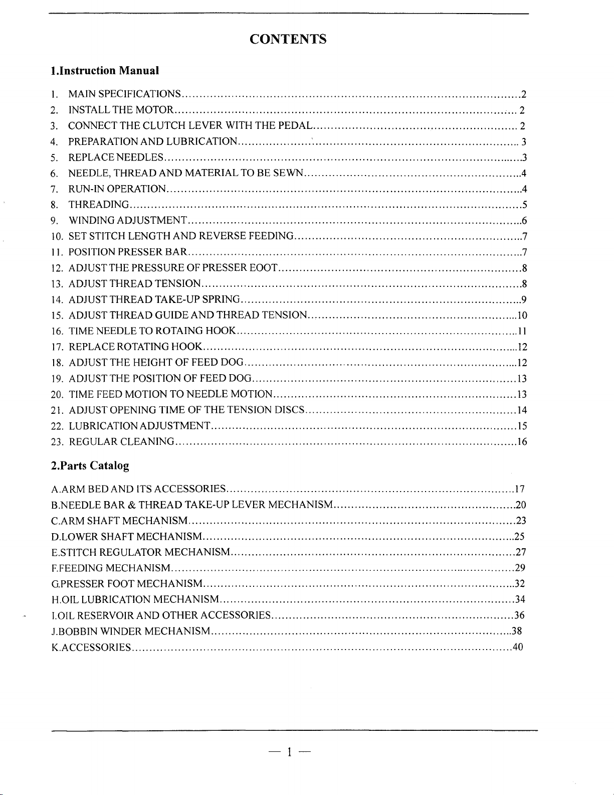
CONTENTS
WITH
THE
PEDAL.
..................... ' ...........................................................
SEWN
REVERSE FEEDING
PRESSER
...........................................................................................
THREAD
HOOK
..........................................................................................
FEED DOG
THE
.......................................................................................
EOOT
.....................................................................
................................................................................
TENSION
................................................................................
DOG
..............................................................................
...........................................................................
MOTION
TENSION DISCS
.....................................................................
.........................................................
..............................................................
.................................................................
............................................................
............................................................
2
, ... 2
2
3
3
4
.4
5
6
7
7
8
8
9
10
11
12
12
13
13
14
15
16
2.Parts Catalog
A.ARM BED
B.NEEDLE BAR &
C.ARM SHAFT
D.LOWER SHAFT
E.STITCH REGULATOR
F.FEEDING
G.PRESSER FOOT
H.OIL LUBRICATION
!.OIL RESERVOIR
J.BOBBIN WINDER
K.ACCESSORIES
AND
ITS
ACCESSORIES
THREAD
MECHANISM
MECHANISM
MECHANISM
MECHANISM
MECHANISM
AND
MECHANISM
............................................................................................................
..................................................................................
TAKE-UP LEVER
.............................................................................................
.........................................................................................
MECHANISM
..................................................................................................
OTHER
ACCESSORIES
.................................................................................
.........................................................................................
....................................................................................
......................................................................................
MECHANISM
.....................................................................
....................................................
-1-
17
20
23
25
27
29
32
34
36
38
40
1.
MAIN SPECIFICATIONS
1)
Max. sewing speed: 5000-5500 spm.
Stitch length: 0-5mm ( reverse feeding available
2)
3) Presser foot lift: 5.5mm ( 13mm by knee
4) Needle bar stroke: 31.8mm.
5) Take-up lever stroke: 58mm.
6) Needle: No.9-No.14 ( DB X 1
7) Head weight: 29.5 kg.
8) Head size: 520 X 178 X 335mm.
9) Motor power:
0.4kw
(clutch
16 X 231
motor).
).
).
).
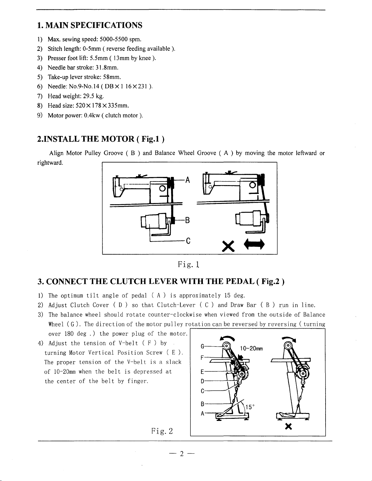
2.INSTALL THE MOTOR ( Fig.l )
Align Motor Pulley Groove ( B ) and Balance Wheel Groove ( A ) by moving the motor leftward or
rightward.
x+-+
Fig. 1
3. CONNECT THE CLUTCH LEVER WITH THE PEDAL ( Fig.2 )
1)
The
optimum
2)
Adjust Clutch Cover ( D )
3)
The
balance wheel should
Wheel
over
4)
Adjust the
turning
The
of
the
(G).
180
proper
10-20mm
center
deg
Motor
tension
when
of
tilt
angle
The
direction
. )
the
tension
Vertical
the
the
belt
of
power
of
V-bel t ( F )
Position
of
the V-belt
belt
is
by
pedal
so
that
rotate
of
the motor
plug
depressed
finger.
(A)
counter-clockwise
of
Screw ( E).
is a slack
is
approximately
Clutch-Lever ( C )
pulley
the motor.
by
at
rotation
15
deg.
and
Draw
Bar ( B ) run in
when
viewed
can
D--~~'LI
be
reversed
from
the
c------·
8----¥~
A---e~~
outside
by
reversing
line.
of Balance
(turning
Fig. 2
-2-
X
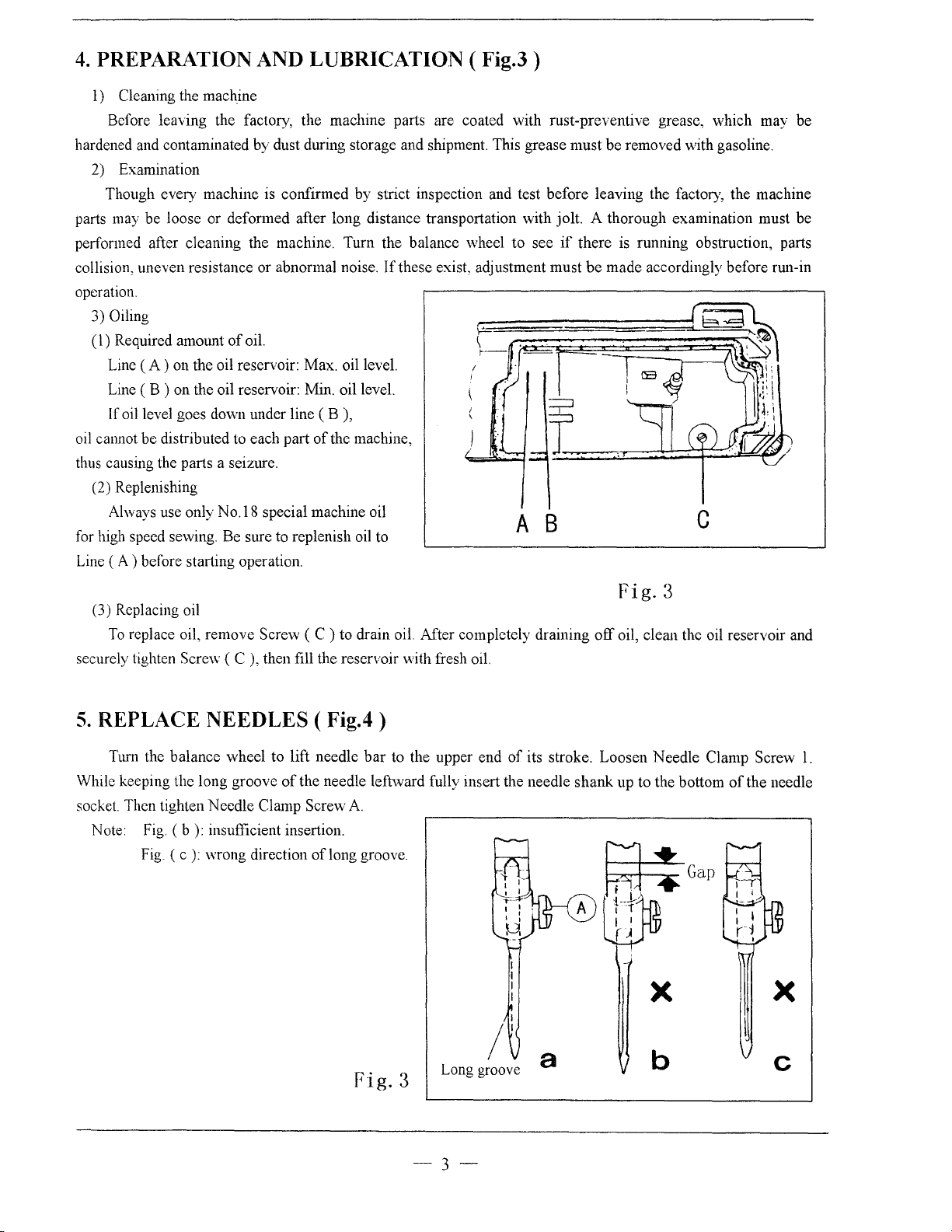
4.
PREPARATION AND LUBRICATION (
l)
Cleaning the machine
Before leaving the factory, the machine parts are coated with rust-preventive grease, which may be
hardened and contaminated by dust during storage and shipment. This grease must be removed with gasoline.
2) Examination
Though every machine is confirmed by strict inspection and test before leaving the
parts may be loose or deformed after long distance transportation with jolt. A thorough examination must be
performed after cleaning the machine. Turn the balance wheel to see
If
collision, uneven resistance or abnormal noise.
operation.
3) Oiling
(
1)
Required amount
(A)
Line
Line ( B ) on the oil reservoir: Min. oil level.
If oil level goes down under line ( B ),
oil cannot be distributed to each part
thus causing the parts a seizure.
(2) Replenishing
Always use only
for high speed sewing. Be sure to replenish oil to
(A)
Line
on the oil reservoir: Max. oil level.
before starting operation.
of
oil.
No.l8
special machine oil
of
the machine,
these exist, adjustment must
Fig.3)
A B
factOJ)',
if
there is running obstruction, parts
be
made accordingly before run-in
the machine
c
(3) Replacing oil
To
replace oil, remove Screw (
Screv-;
securely tighten
5.
REPLACE NEEDLES (
Ttml the balance wheel to lift needle
While keeping the long groove
socket Then tighten Needle
Note
Fig.
(b):
Fig. ( c
( C ), then fill the reservoir with fresh oil.
of
Clamp Sere\\·
insufficient insertion.
):
wrong direction
Fig.3
C)
to drain oil. After completely draining
off
oil, clean the oil reservoir and
Fig.4)
bar
to the upper end
the needle leftward fully insert the needle shank up to the bottom
A.
of
long groove.
of
its stroke. Loosen Needle Clamp Screw
X
of
the needle
1.
a
Fig.
3
Long groove
-3-
b

6.
NEEDLE,
THREAD
AND
JVIATERIAL
TO BE
SEWN
Needle Size Thread Number
;j
9
;!
J1
tl
14
11
16
7.
RUN-IN OPERATION
Run-in operation is required for a new se\ving machine, or a
considerable length
1)
Remove Red Rubber Plugs
2) Lift Presser Foot
3) Run the machine at a low speed ( 2000-2500spm ) to check oil distributing condition through Oil Check
Window
vvhich
can be adopted according to the nature
(C).
4) Perform run-in operation at 2000-2500spm for 30minutes. After a lapse
the working speed is increased gradually and the machine runs sufficiently well, the high speed 5000spm
of
time.
(A)
(B).
100
li
80-60
II
60-50
'f
50-30
(Fig.
on the top
of
the work.
j:;
-80
II
ti
li
II
5)
of
georgette,
silk, muslin, poplin
cotton, light woolen
woolen, tarpaulin, thin leather
the ann and replenish suilicient amount
Material
hard
crepe
sewing
machine left out operation for a
of
oil.
of
one month
of
service during
A--------~--~------------~
Fig.
5
c
--4-
8.
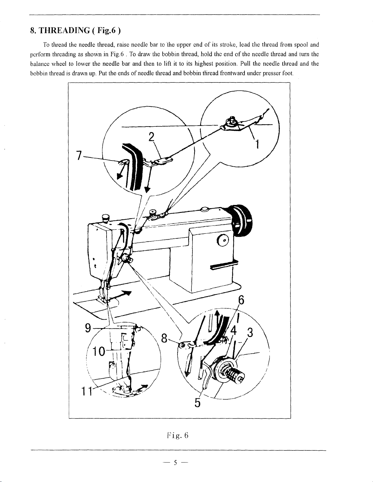
THREADING (
To
thread the needle thread, raise needle bar
perform threading
balance wheel
bobbin thread
to
is
drawn
Fig.6)
to
the upper end
as
shown in Fig.6 .
lower the needle bar and then to lift it
up.
Put the ends
To
draw the bobbin thread, hold the end
of
needle thread and bobbin thread frontward tmder presser foot.
of
its
stroke, lead the thread from spool and
of
the needle thread and tum
to
its highest position. Pull the needle thread and the
the
Fig.
6
-5-
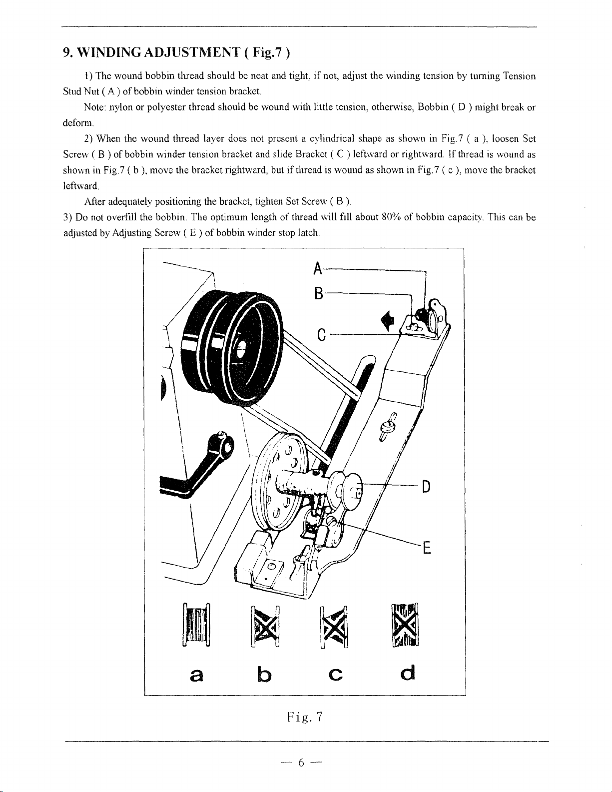
9.
WINDING ADJUSTMENT (
l)
The wound bobbin thread should
Stud Nut
dcfom1.
Screw ( B )
shown in Fig. 7 ( b
leftward.
3) Do not overfill the bobbin. The optimum length
adjusted
(A)
of
bobbin winder tension bracket.
Note: nylon or polyester thread should be wound with little tension, otherwise, Bobbin ( D ) might break or
2) When the wound thread layer does not present a cylindrical shape as shown
of
bobbin winder tension bracket and slide Bracket ( C ) leftward or rightward. If thread
),
move the bracket rightward, but
After adequately positioning the bracket, tighten Set Screw
by
Adjusting Screw ( E )
of
bobbin winder stop latch.
Fig.7)
be
neat and tight,
if
not, adjust the winding tension by turning Tension
in
Fig.7 ( a
if
thread is wound as shown in Fig. 7 ( c ), move the bracket
(B).
of
thread will fill about 80%
of
bobbin capacity. This can be
).
is
8------.
loosen Set
wound
as
~
~
-
a
b
Fig.
-6-
c
7
m
~
d
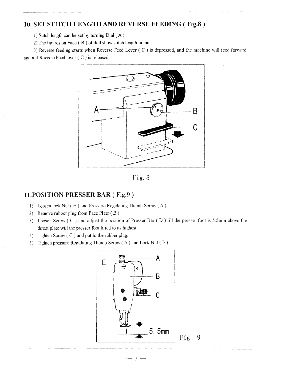
10.
SET STITCH
l)
Stitch length can be set
2) The figures on Face
3) Reverse feeding starts when Reverse Feed Lever ( C )
again
if
Reverse Feed lever ( C ) is released.
LENGTH
by
turning Dial
(B)
of
dial show stitch length in
AND REVERSE FEEDING ( Fig.8 )
(A).
mm.
is
depressed, and the machine will feed forward
Fig.
II.POSITION PRESSER BAR ( Fig.9 )
I) Loosen lock Nut ( E ) and Pressure Regulating Thumb Screw
2) Remove mbber plug from Face Plate
3) Loosen Screw ( C ) and adjust the position
throat plate will the presser foot lifted to its highest.
4) Tighten
5) Tighten pressure Regulating Thumb
Screw ( C ) and put in the rubber plug.
(B).
of
Presser
Screw
(A)
and Lock Nut (
E-~::.:3....1:::::::-
~----A
~:
•
8
Bar
(A).
(D)
till the presser foot
E).
is
5.5mm above the
--~
____,.,..---
5 . 5
mm
..
-7-
Fig.
9
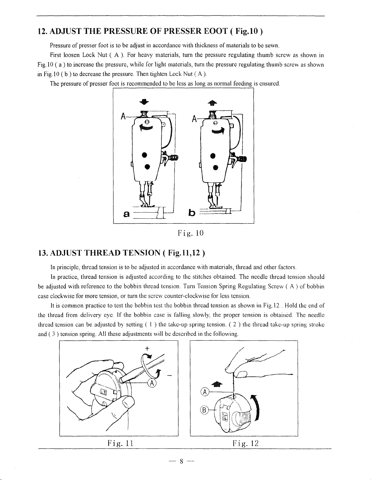
12.
ADJUST THE PRESSURE
OF
PRESSER EOOT ( Fig.10)
Pressure
First loosen Lock
Fig.l
0 ( a ) to increase the pressure, while for light materials, turn the pressure regulating thumb screw
in
Fig.l 0
The pressure
of
presser foot
(b)
to decrease the pressure. Then tighten Lock Nut
of
presser foot is recommended
is
to be adjust in accordance with thickness
Nut
( A
).
For heavy materials,
to
tum
be less
of
materials to be sewn.
the pressure regulating thumb screw
(A).
as
long
as
normal feeding
is
ensured .
•
as
shown in
as
shown
Fig.
10
13.
ADJUST THREAD TENSION ( Fig.11,12)
In
principle, thread tension is to be adjusted in accordance with materials, thread and other factors.
In
practice, thread tension
be adjusted with reference to the bobbin thread tension. Tum Tension Spring Regulating Screw ( A )
case clockwise for more tension, or turn the screw counter-clockwise for less tension.
It
is
common practice to test the bobbin test the bobbin thread tension as shown in
the thread from delivery eye.
thread tension can be adjusted
3)
and (
tension spring. All these adjustments will be described in the following.
is
adjusted according to the stitches obtained. The needle thread tension should
Fig.l2
If
the bobbin case
by
setting ( l ) the take-up spring tension. ( 2 ) the thread take-up spring stroke
is
falling
slovvly,
the proper tension
/
. Hold the end
is
obtained. The needle
of
bobbin
of
Fig.
11
- 8
--
Fig.
12
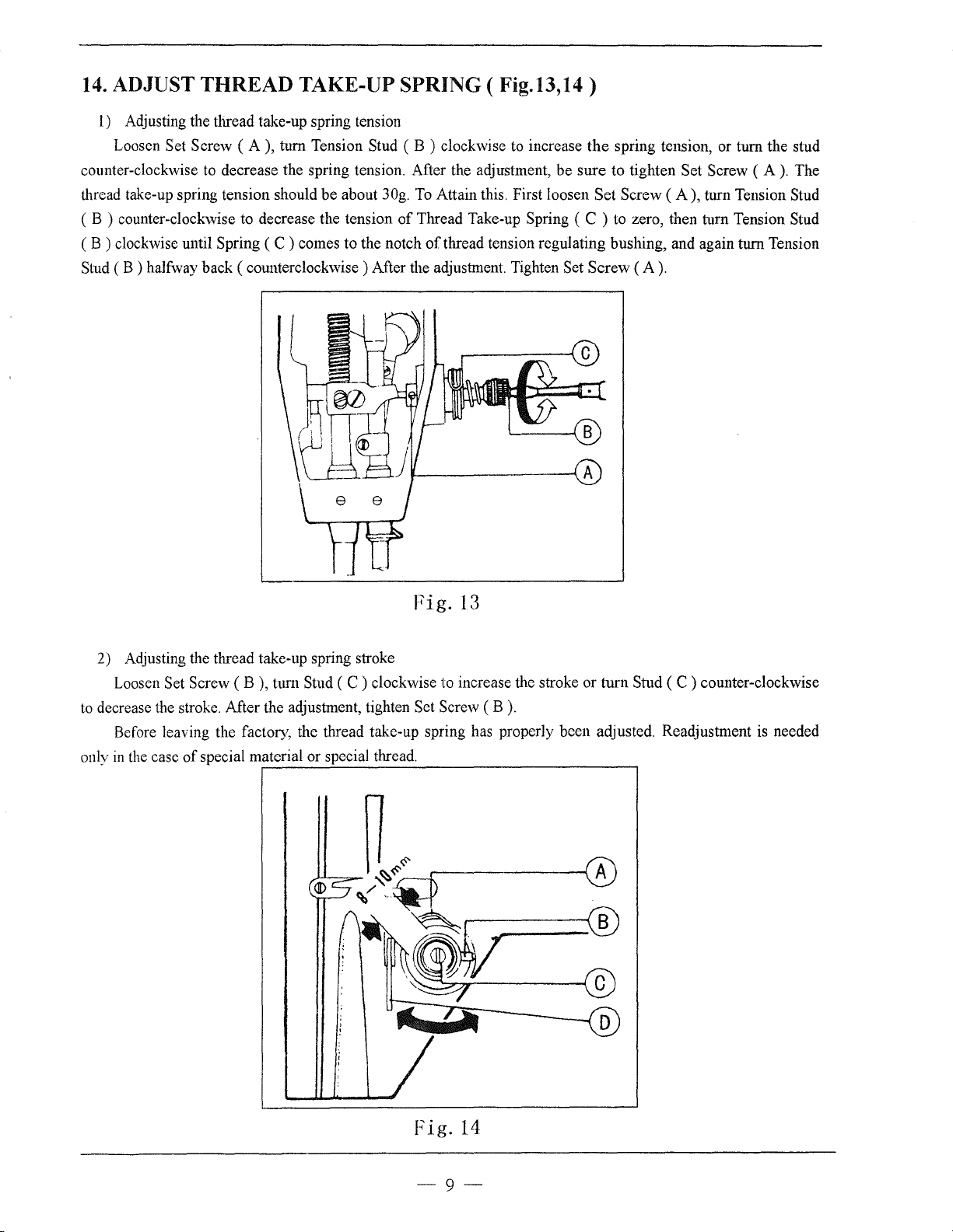
14.
ADJUST
1)
Adjusting the thread take-up spring tension
Loosen
counter-clockwise
thread take-up spring tension should be about
( B ) counter-clockwise to decrease the tension
( B ) clockwise until Spring ( C ) comes to the notch
Stud
(B)
halfway back (counterclockwise) After the adjustment. Tighten Set Screw
THREAD
Set Screw
to
decrease the spring tension. After the adjustment, be sure to tighten Set Screw ( A
TAKE-UP
(A),
turn Tension Stud ( B ) clockwise
SPRING ( Fig.13,14)
30g.
of
to
increase
To
Attain this. First loosen Set Screw
Thread Take-up Spring ( C ) to zero, then turn Tension Stud
of
thread tension regulating bushing, and again turn Tension
the
spring tension, or turn the stud
(A),
turn Tension Stud
(A).
).
The
Fig.
13
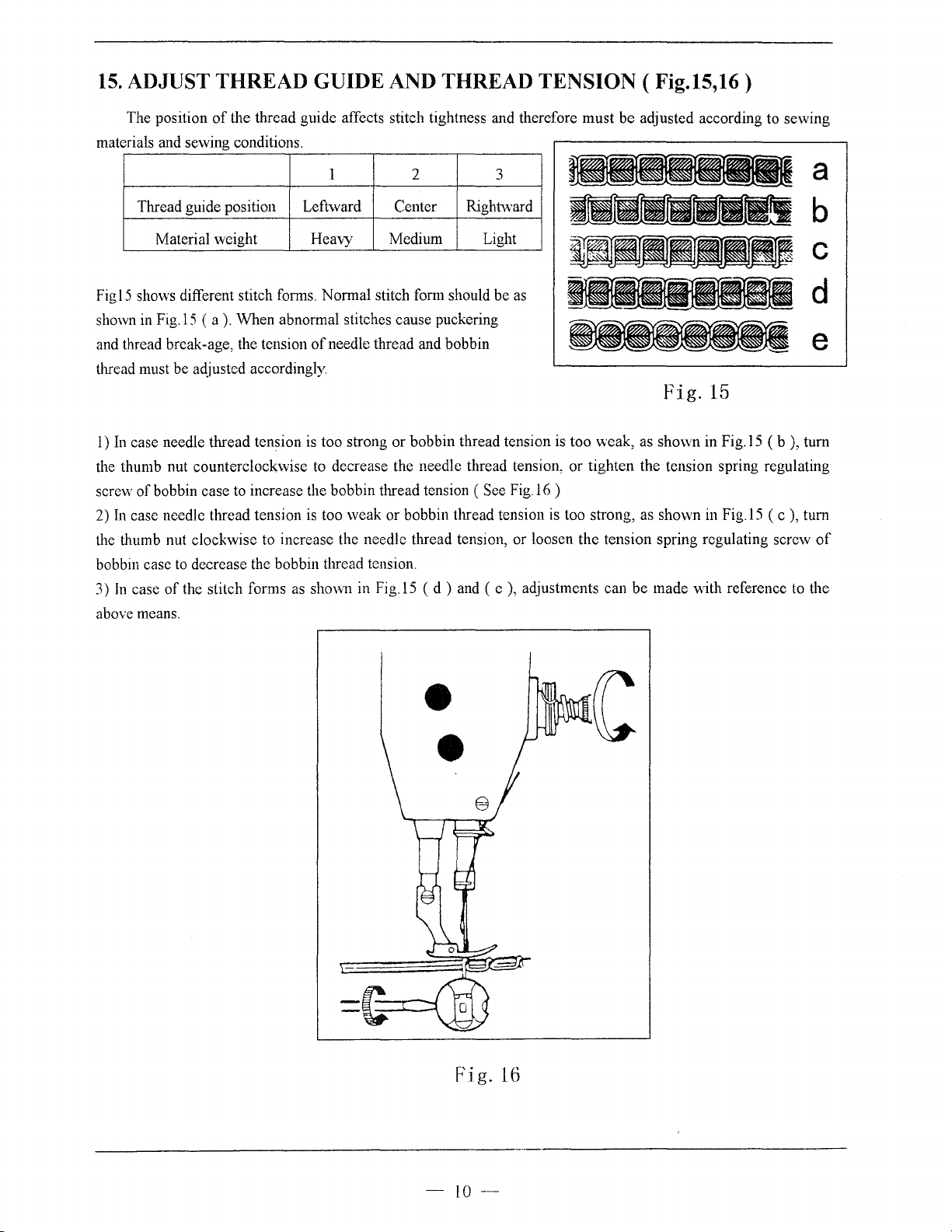
2) Adjusting the thread take-up spring stroke
Loosen
to
decrease the stroke. After the adjustment, tighten Set Screw
Before leaving the factory, the thread take-up spring has properly been adjusted. Readjustment
in
only
Set Screw ( B ), tum Stud ( C ) clockwise to increase the stroke or turn Stud ( C ) counter-clockwise
(B).
the
case
of
special material or special thread.
~----~------------------------------~
,---------1
A
is
needed
Fig.
14
-9--
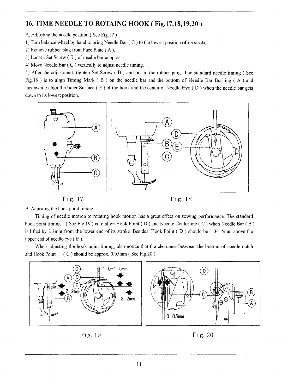
15.
ADJUST THREAD GUIDE AND THREAD TENSION (
Fig.l5,16)
The position
materials and sewing conditions.
Thread guide position Leftward
Material weight
of
the thread guide affects stitch tightness and therefore must be adjusted according to sewing
1 2 3
Center
Heavy Medium Light
Rightward
a
b
c
Figl5 shows different stitch forms. Normal stitch fonn should be as
shown
in
Fig.l5
(a).
When abnormal stitches cause puckering
and thread break-age, the tension
thread must be adjusted accordingly.
I)
In
case needle thread tension
the thumb nut counterclockwise to decrease the needle thread tension, or tighten the tension spring regulating
screw
of
bobbin case to increase the bobbin thread tension ( See
2)
In
case needle thread tension is too weak or bobbin thread tension is too strong, as shown
the thumb nut clockwise to increase the needle thread tension, or loosen the tension spring regulating screw
bobbin case to decrease the bobbin thread tension.
3)
In
case
of
the stitch forms as shovvn in
above means.
of
needle thread and bobbin
Fig.
is
too strong or bobbin thread tension is too weak, as shown in
Fig.l6
)
Fig.l5
(d)
and
(e),
adjustments can be made with reference to the
15
in
Fig.l5
Fig.l5
d
e
( b ), turn
( c ), tum
of
e
e
Fig.
16
-IO-
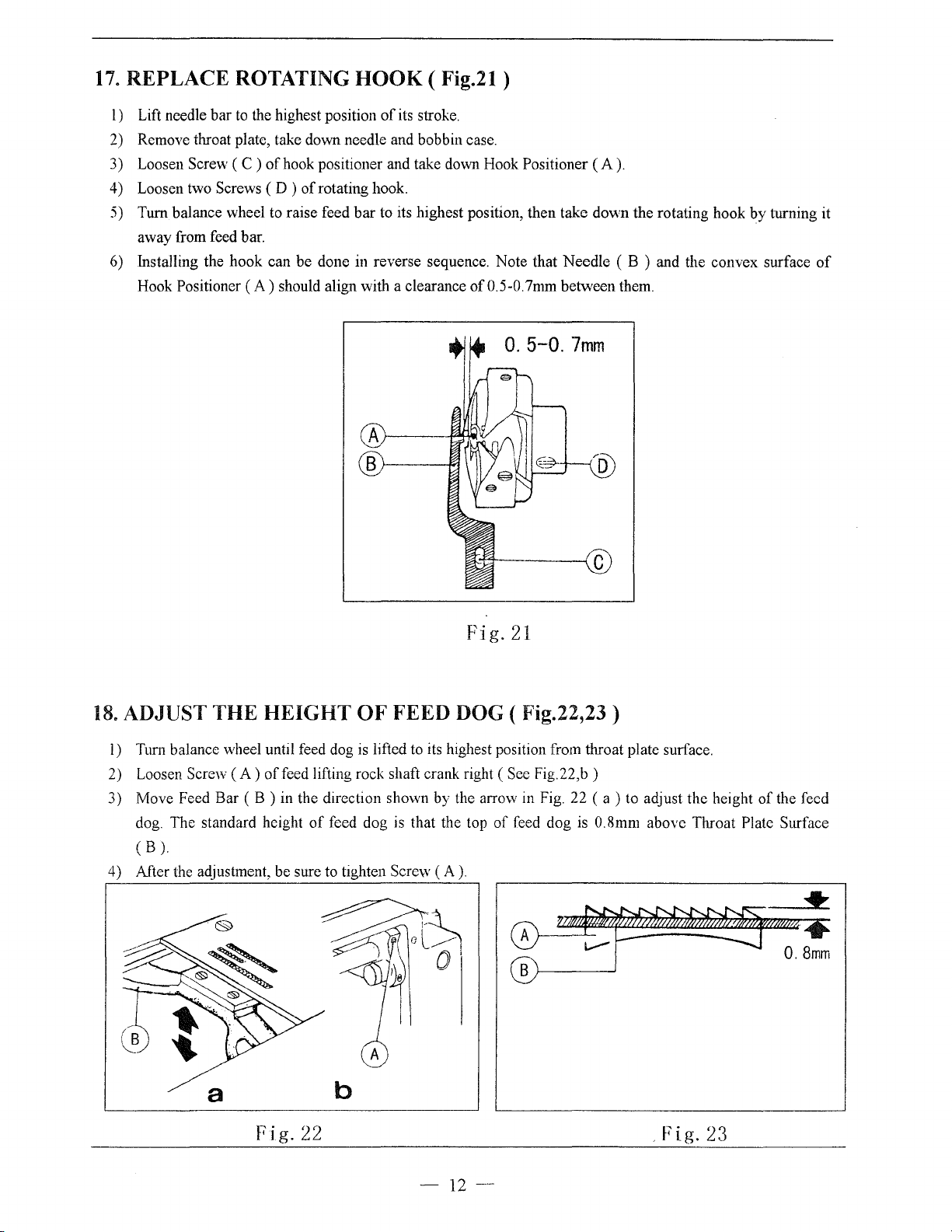
16.
TIME NEEDLE TO ROTAING HOOK ( Fig.17,18,19,20)
A.
Adjusting the needle position ( See Fig.l7 )
l)
Turn balance wheel by hand
2)
Remove rubber plug from Face Plate
3) Loosen Set Screw ( B )
4) Move Needle Bar
5)
Mter
the adjustment, tighten Set Screw ( B ) and put
is
Fig.l8 )
meanwhile align the Inner Surface
down
to
to
its lowest position.
(C)
align Timing Mark ( B )
to
bring Needle Bar ( C )
(A).
of
needle bar adaptor.
vertically
to
aqjust needle timing.
(E)
of
to
the lowest position
in
the rubber plug.
on
the needle bar and the bottom
the hook and the center
of
Needle
of
its stroke.
The
standard needle timing ( See
of
Needle Bar Bushing ( A ) and
Eye
(D)
when the needle bar gets
Fig.
17
B.
Aqjusting the hook point timing
Timing
hook point timing ( Sec Fig.l9 )
is
lifted
upper end
When adjusting the hook point timing, also notice that the clearance between the bottom
and Hook
of
needle motion to rotating hook motion has a great effect on sewing performance. The standard
by
2.2mm from the lower end
of
needle eye
Point
(E).
(C)
should be approx. 0.05mm
Fig.
is
to align Hook Point ( D ) and Needle Centerline ( C ) when Needle Bar ( B )
of
its stroke. Besides, Hook Point ( D ) should be l.0-1.5mrn above the
(See
Fig.20)
19
Fig.
0.
05mm
18
Fig.20
of
needle notch
-
11-
17.
REPLACE ROTATING
1)
Lift needle bar
2) Remove throat plate, take down needle and bobbin case.
3) Loosen Screw (
4) Loosen two Screws ( D )
5)
Turn balance wheel
away from feed bar.
6) Installing the hook can be done in reverse sequence. Note that Needle ( B ) and the convex surface
Hook Positioner
to
the highest position
C )
of
hook positioner and take down Hook Positioner
of
to
raise feed bar
(A)
should align with a clearance
HOOK
of
rotating hook.
to
( Fig.21)
its stroke.
(A).
its highest position, then take do\vn the rotating hook
of
0.5-0.
7mm
between them.
0.
5-0.
7mm
by
turning it
of
18.
ADJUST THE
l)
Tum balance wheel until feed dog is lifted
2) Loosen Screw
3) Move Feed Bar
dog. The standard height
(B).
4) After the adjustment, be sure
HEIGHT
(A)
of
(B)
in the direction shown by the arrow in Fig. 22
feed lifting rock shaft crank right
of
OF
feed dog
to
tighten Screw
Fig.21
FEED DOG ( Fig.22,23)
to
its highest position from throat plate surface.
(See
Fig.22,b)
(a)
to adjust the height
is
that the top
(A).
of
feed dog is 0.8mm above Throat Plate Surface
of
the feed
a b
Fig.
22 .
-12-
Fig.
23
 Loading...