

Page 1
Purchasing
Copy
Dept
HIGH
GC2698-1/GC2698-1B
CYLINDER-BED UNISON
Instruction Manual
LEAD
FEED
SEWING
MACHINE
Parts
SHANGHAI
HUIGONG
N0.3
Catalog
SEWING MACHINE FACTORY
Page 2

----~
Page 3
The Machine Conforms to the Following European Regulations:
EN60204-31:
19.96-.
98/37/EC-. DIN5310-. DIN5318-. 73/23/EEC
(93/68/EEC)
CONTENTS
INSTRUCTION
1, SAFETY .......................................................................................................................................................... 1
1)
GENERAL SAFETY TIPS ............................................................................................................................... 1
2)
IMPORTANT POINTS FOR THE EMPLOYER ............................................................................................. 1
3)
SERVICE AND TECHNICAL PERSONNEL ................................................................................................ 1
4)
DANGER TIPS ............................................................................................................................................... 2
2,
TESTING, TRANSPORT& STORAGE .......................................................................................................... 3
1)
TIPS ON TESTING ........................................................................................................................................ 3
2)
TRANSPORT WITHIN THE CUSTOMER SITE ........................................................................................... 3
3)
STORAGE ........................................................................................................................................................ 3
3,
INSTALLATION & FIRST OPERATION ....................................................................................................... 3
MANUAL
1)
ASSEMBLING THE BOBBIN STANDS ........................................................................................................ 3
2)
FIRST OPERATION ........................................................ : ................................................................................ 3
4,
SPECIFICATIONS ........................................................................................................................................... 3
5,
PREPARATION ................................................................................................................................................ 4
1)
ATTACHING THE NEEDLE ........................................................................................................................... 4
2)
WINDING THE LOWER THREAD, REGULATING THE TENSION OF THE THREAD ......................... .4
3)
TAKING OUT THE BOBBIN CAPSULE ....................................................................................................... 5
4)
ROUTING THE UPPER THREAD ................................................................................................................. 6
5)
REGULATING THE TENSION OF THE THREAD ....................................................................................... 6
6,
STITCH LENGTH ADJUSTING LEVER I REVERSE SEWING .................................................................. 7
7,
MAINTENANCE & CARE .............................................................................................................................. 7
1)
MAINTENANCE AND CARE INTERVALS .................................................................................................. 7
2)
CLEANING ...................................................................................................................................................... 7
3)
GENERAL OILING ......................................................................................................................................... 8
4)
OILING THE HEAD ...................................................................................................................................... 8
5)
OILING THE ROTATING HOOK ................................................................................................................... 8
8,
ADJUSTMENT ................................................................................................................................................ 8
1)
TIPS FORADJUSTMENT ............................................................................................................................... 8
-I-
Page 4
2)
ABBREVIATIONS ........................................................................................................................................... 9
3)
POSITION OF THE FEED DOG ..................................................................................................................... 9
4)
NEEDLE
5)
NEEDLE IN THE MIDDLE OF THE STITCHING HOLE .......................................................................... 1 0
6)
PRESSER FOOT, WALKING FOOT AND FEED DOG SLIDING MOVEMENT ......................................
7)
HOOK POSITIONER, GRAB DISTANCE AND NEEDLE HEIGHT ..........................................................
8)
HYDRAULIC MOVEMENT OF THE WALKING FOOT AND PRESSER FOOT .....................................
9)
PRESSER FOOT ............................................................................................................................................
HEIGHT(PRE-ADJUSTMENn
................................................................................................... 10
ll
11
12
12
10) UPPER THREAD TENSION REGULATION ...............................................................................................
11) THREAD TAKE-UP SPRING ........................................................................................................................
12)
BOBBINWINDER
13)
ADJUSTMENT OF PRESSER PRESSURE ................................................................................................
......................................................................................................................................
CATALOG
A,
ARM BED AND ITS ACCESSORIES ( 1 ) ................................................................................................
A,
ARM BED AND ITS ACCESSORIES
B,
FEEDING AND FEED LIFTING & LOWER SHAFT MECHANISM ........................................................
C,
ARM SHAFTMECHANISM ........................................................................................................................
D,
STITCH REGULATOR MECHANISM ........................................................................................................ 24
E,
PRESSER FOOT MECHANISM ...................................................................................................................
F
'·
NEEDLE BAR FEEDING MECHANISM (
F,
NEEDLEBARFEEDINGMECHANISM
G,
ACCESSORIES ............................................................................................................................................. 32
(2)
................................................................................................
1)
..........................................................................................
(2)
.......................................................................................... 29
13
13
13
14
15
16
19
22
26
28
-2-
Page 5
1.
SAFETY
1) GENERAL SAFETY TIPS
CD
The machine should only be used after studying the accompanying instruction manual and only
specially instructed operating staff
by
@ Before bringing the machine into service read the safety tips and the instruction manual
manufacturer.
@ The machine may only
protective fittings. All relevant safety regulations should also
@ When changing sewing tools (for example needle, presser foot, needle plate and bobbin winder),when
up,
threading
unplugged or switched off at the main switch.
@ Daily maintenance work should only be carried out
® Repair work
specially trained personnel
(])
@ Working
when leaving the work place
as
well
Working on the electrical equipment should only be carried out by qualified electricians.
on
active parts and equipment are not permitted.
® Only the spare parts provided
spare parts and accessories that are not supplied
use
of
such products can in certain circumstances reduce the predetermined quality
be
used according
as
special maintenance work should only
by
us
should be used during repairs.
as
to
their regulations and not without the accompanying
be
observed.
well
as
during maintenance work the machine should
by
specially trained personnel.
by
us
are also not tested or passed
be
carried out
We
by
explicitly point out that the
by
us. The installation or
of
your machine.
of
the engine
skilled workers or
We
be
take
no
responsibility
2)
IMPORTANT POINTS
CD
This
machine operators. It
@ Operation and maintenance personnel must be instructed
working methods.
@
The
@
The
@ Further information can
3)
SERVICE AND
(1) Service
Service personnel are responsible for the preparing, running and cleaning
elimination
CD
to
®
to
for
damage caused
instruction manual
is
necessary
employer must ensure that the machine
employer should make sure that only authorised persons are permitted
TECHNICAL
by
the use
FOR
is
a component
to
read the manual before using the machine for the first time.
be
obtained from the responsible sales office.
of
non-original parts.
THE
EMPLOYER
of
is
only used
the machine and must always
on
if
it
is
in perfect condition.
PERSONNEL
Personnel
of
faults in the sewing. Service personnel must observe the following points:
follow the safety guidelines in the instruction manual
avoid any type
of
work which may reduces the safety
of
the machine
safety features
to
work on the machine.
of
the machine
be
at the disposal
of
the machine and safe
as
well
of
as
the
the
-1-
Page 6
@ to wear tight-fitting clothes and avoid wearing jewellery, like necklaces and rings
@ to report immediately changes in the machine which may reduce safety to the employer.
(2) Technical
Technical personnel are responsible for the lubrication, maintenance, repair and adjustments
CD
p"ersonnel
To
follow safety guidelines in the instruction manual
Technical
® Before beginning maintenance work the main switch must
will not be switched on again.
Personnel
must observe the following points:
be
switched
off
and
@ Working on active parts and equipment is not permitted.
@ After repair and maintenance work the protective covering must
must be closed.
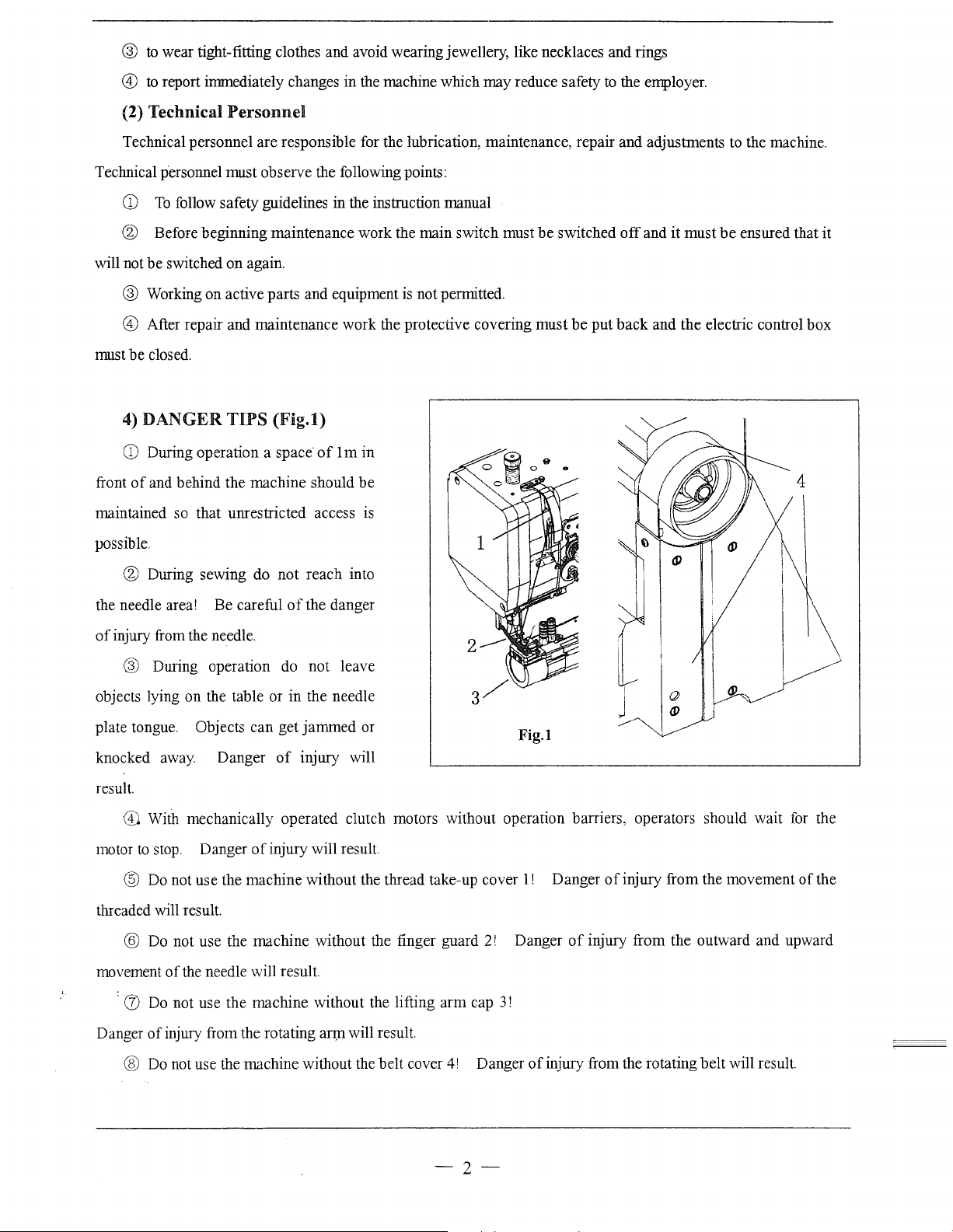
4)
DANGER
CD
During operation a space
of
front
maintained so that umestricted access
possible.
and behind the machine should be
TIPS
(Fig.l)
of
lm
in
IS
be
put
back and the electric control box
it
must
to
the machine.
be
ensured that it
® During sewing do not reach into
of
the needle area! Be careful
of
injury from the needle.
@ During operation
objects lying on the table or in the needle
plate tongue. Objects can get jammed or
knocked
result.
away.
Danger
the danger
do
not leave
of
injury will
Fig. I
® With mechanically operated clutch motors without operation barriers, operators should wait
to
motor
threaded will result.
movement
stop. Danger
@
Do
@
Do
:
(J)
Do
not use the machine without the thread take-up cover
not use the machine without the finger guard
of
the needle will result.
not use the machine without the lifting arm cap
of
injury will result.
2!
1!
Danger
3!
Danger
of
injury from the movement
of
injury from the outward and upward
for
of
the
the
Danger
of
injury from the rotating
@
Do
not use the machine without the belt cover
an:n
will result.
4!
Danger
of
injury from the rotating belt will result.
-2-
Page 7

2.
TESTING,
1)
TIPS ON
TRANSPORT
TESTING
& STORAGE
The machine was tested before delivery according
2)
TRANSPORT
Transport within the customer site is
is
the machine
correctly transported.
WITHIN
THE
not
3) STORAGE
The machine can
If
the machine is
against corrosion, with an oil film for example.
3. INSTALLATION &
The machine should only
regulations should
technical data).
the installation site.
l)ASSEMBLINGTHE
It
be
stored unused for up
to
be
stored longer the individual parts,
FIRST
be
installed and started
be
observed. Suitable electricity supply must
must
be
ensured that there is an even and solid ground surface
OPERATION
BOBBIN STANDS
to
the EN60204-3-1 editionl/86.
CUSTOMER SITE
the responsibility
to
6 months.
by
of
the manufacturer.
It
should
in
particular the sliding plates, should
qualified technical personnel. All the relevant safety
It
should
be
protected against dirt and moisture.
be
available at the installation site (see
as
well
as
be
ensured that
be
protected
sufficient lighting at
Place the bobbin stands in the drill hole in the table plate and fix them into place with the enclosed nuts.
2)
FIRST OPERATION
Before the first operation check the electric cables in case
CD
Clean and oil the machine thoroughly
@ Allow technical specialists
main supply and whether
it
is properly plugged
to
check whether the machine's motor may
in.
If
there is any deviation,
® When the machine is running the balance wheel should
technical specialists adjust the motor.
4.
SPECIFICATIONS
Max. Sewing Speed
Max. Stitch Length
Thread Take-up Lever Stroke
Needle Bar Stroke
Presser Foot Stroke
Alternating Movement
Needle
Rotating Hook HSH-BTR
Lubrication System
Electric Machinery
-
By Hand
of
any possible damage.
be
connected
do
not start the machine.
be
turned towards the operator. Otherwise let
2200rpm
6mm
59.55mm
33.4mm
I
lsmm
DPX35LR
Manual
1400 rpm 370W
ByKnee
14#-16#
113mm
to
the available
-3-
Page 8
5
..
Preparation
CD
All regulations and guidelines in this manual should
safety regulations.
be
observed,
with
special attention being paid to
® All preparation
work the machine should
unplugging it.
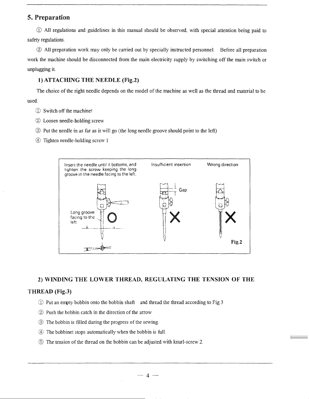
1)
ATTACHING
The choice
used.
CD
Switch
of
off
work
may
only
be
carried out
be
disconnected from the main electricity supply
THE
NEEDLE (Fig.2)
the right needle depends on the model
the machine!
by
specially instructed personnel. Before all preparation
of
the machine as well as the thread and material
® Loosen needle-holding screw
® Put the needle in as far as it will go (the long needle groove should point
@)
Tighten needle-holding screw 1
nsuff1cient insertion
Insert the needle until it bottoms, and
t1ghten
groove m the needle facing to the left.
the screw keeping the long
I
by
switching
to
off
the left)
Wrong direction
the main switch or
to
be
Long
groove
facing to the .
left
I
=r-==-$==
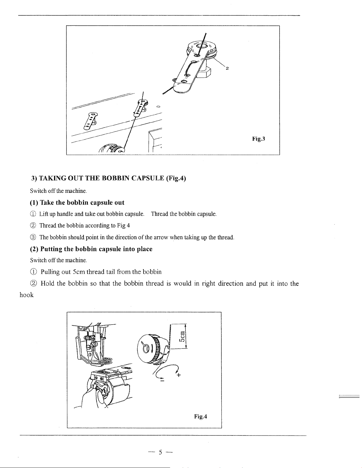
2)
WINDING
THREAD (Fig.3)
CD
Put an empty
® Push the bobbin catch
® The bobbin is filled during the progress
@)
The bobbinet stops automatically when the bobbin
® The tension
THE
LOWER
bobbin
of
onto the bobbin shaft and thread the thread according to Fig 3
in
the direction
the thread on the bobbin can
THREAD, REGULATING
of
the arrow
of
the sewing.
is
full.
be
adjusted with knurl-screw
THE
TENSION
2.
Fig.2
OF
THE
-4-
Page 9
2
Fig.3
3) TAKING
Switch
off
(1) Take
CD
Lift
up
® Thread the bobbin according
® The bobbin should point
(2) Putting
Switch off the machine.
CD
Pulling out
OUT
THE
BOBBIN
the machine.
the
bobbin
handle and take out bobbin capsule. Thread the bobbin capsule.
the
capsule
to
in
the direction
bobbin
Scm
capsule into place
thread tail from the bobbin
CAPSULE (Fig.4)
out
Fig 4
of
® Hold the bobbin so that the bobbin thread
hook
the arrow when taking up the thread.
is
would in right direction and put
it
into the
Fig.4
-5-
-·---~
---------------
Page 10
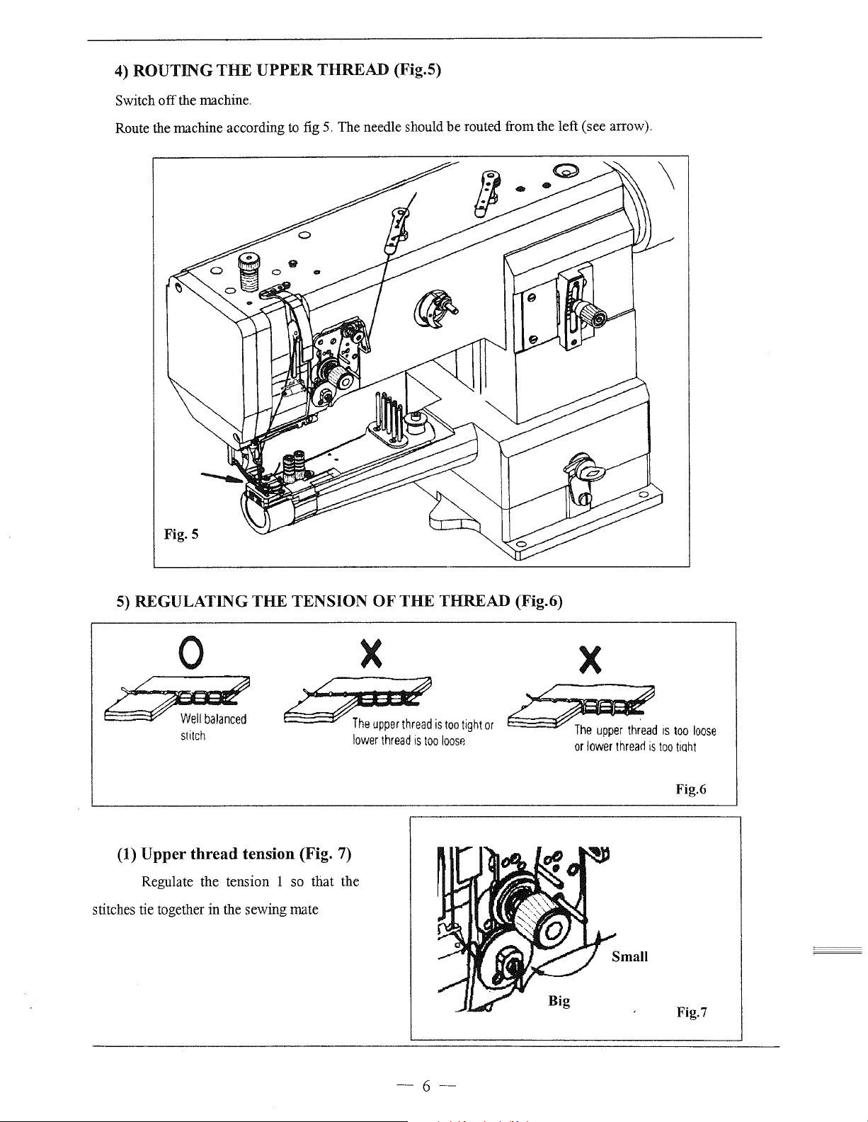
4)
ROUTJNG
Switch
off
THE
the machine.
UPPER
THREAD
(Fig.5)
Route the machine according to fig 5. The needle should
be
routed
from
the
left
(see
arrow).
5)
REGULATJNG
0
6~
stitch
(1)
Upper
Regulate
stitches tie together
thread
the
in
THE
TENSION
Qn~
tension (Fig. 7)
tension
the
1 so
sewing
mate
that
OF
X
n:;er
lovverthread
the
THE
THREAD (Fig.6)
thread
is
too
tight
is
too
loosr.
X
or
~;stoolaos<
or
lovver
threarl
is
too
tiqht
Fig.6
-~--
---
---------
-----
Fig.7
-6-
Page 11
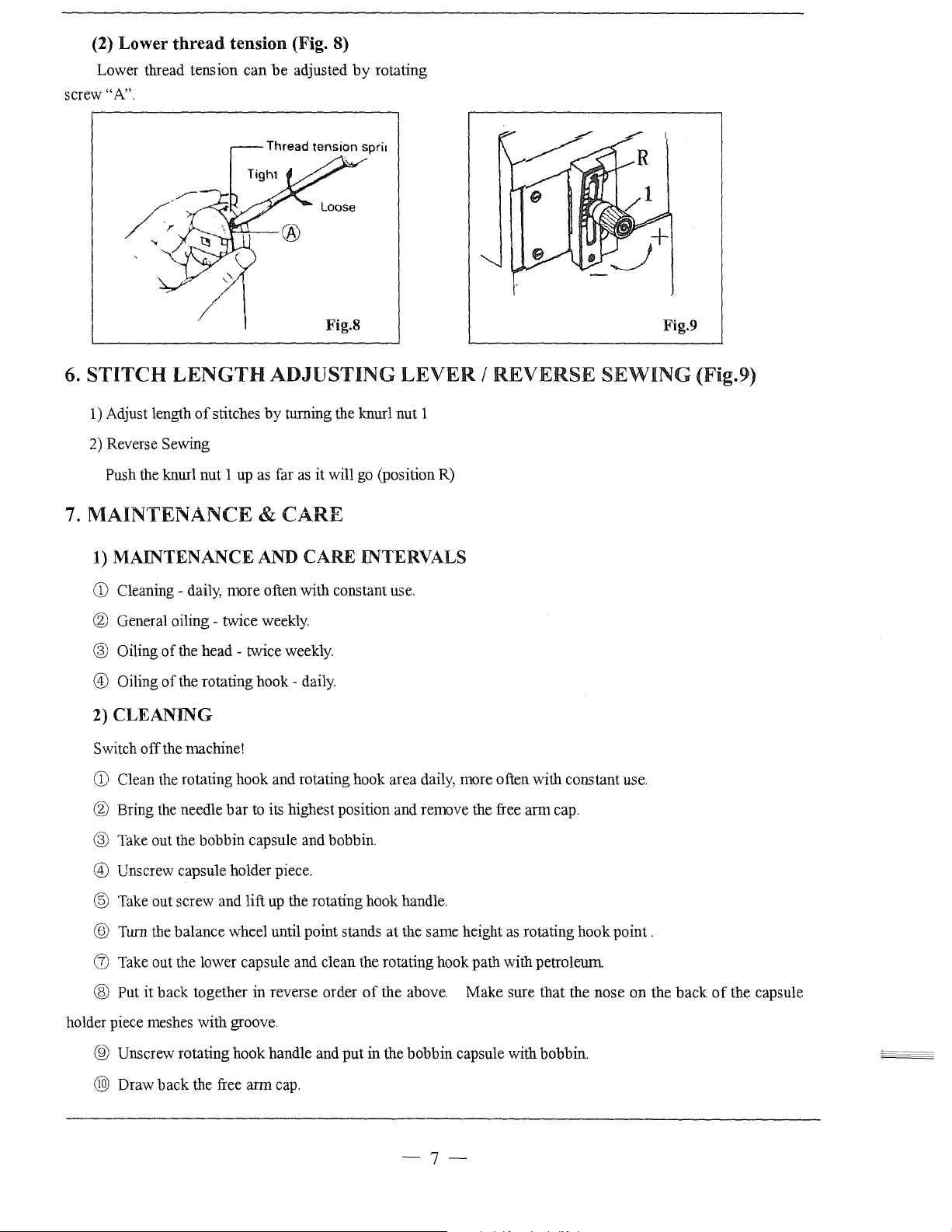
(2) Lower
Lower thread tension can
screw"A".
thread
tension (Fig. 8)
be
adjusted
by
rotating
6.
STITCH
1)
Adjust length
2)
Reverse Sewing
Push the knurl nut 1 up as far
7.
MAINTENANCE &
1)
MAINTENANCE AND CARE INTERVALS
CD
Cleaning - daily, more often with constant use.
LENGTH
of
stitches
® General oiling - twice weekly.
® Oiling
@ Oiling
2)
CLEANING
Switch
of
the head - twice weekly.
of
the rotating hook - daily.
off
the machine!
Fig.8
ADJUSTING
by
turning the knurl nut 1
as
it
will
go
(position R)
CARE
LEVER I REVERSE
Fig.9
SEWING
(Fig.9)
CD
Clean the rotating hook and rotating hook area daily, more often with constant use.
® Bring the needle
bar
to its highest position and remove the free arm cap.
® Take out the bobbin capsule and bobbin.
@ Unscrew capsule holder piece.
@ Take out screw and lift up the rotating hook handle.
@ Turn the balance wheel until point stands at the same height
(!) Take out the lower capsule and clean the rotating hook path with petroleum
® Put it back together
holder piece meshes with groove.
® Unscrew rotating hook handle and
@)
Draw back the free arm cap.
in
reverse order
of
the above. Make sure that the nose
put
in
the bobbin capsule with bobbin.
as
rotating hook point .
-7-
on
the
back
of
the capsule
Page 12
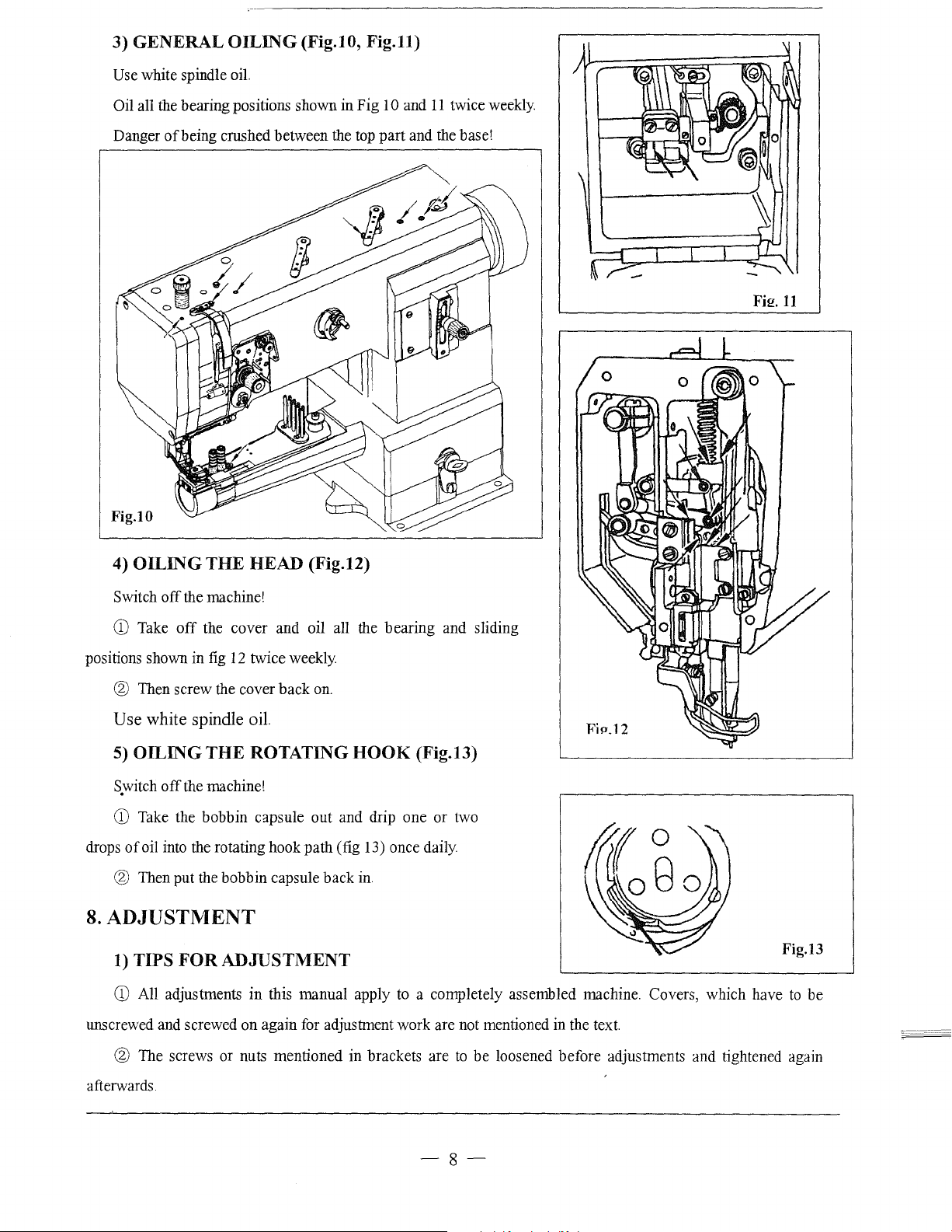
3) GENERAL
Use white spindle oil.
OILING
(Fig.lO,
Fig.ll)
Oil all the bearing positions shown in Fig 10 and
Danger ofbeing crushed between the top part and the base!
Fig.IO
11
twice weekly.
Fi!!.
11
4)
OILING
Switch off the machine!
CD
Take
positions shown in fig
@ Then screw the cover back
THE
HEAD (Fig.12)
off
the cover and oil all the bearing and sliding
12
twice weekly.
Use white spindle oil.
5)
OILING
s.witch
CD
Take the bobbin capsule out and drip one or two
drops
of
oil into the rotating hook path (fig 13) once daily.
@ Then put the bobbin capsule back
8.
ADJUSTMENT
1)
TIPS
CD
All adjustments
THE
off
the machine!
FOR
ROTATING
ADJUSTMENT
in
this manual apply
on.
HOOK
in.
to
(Fig.l3)
a completely assembled machine. Covers, which have
Fig.13
to
be
unscrewed and screwed on again for adjustment work are not mentioned in the text.
@ The screws or nuts mentioned in brackets are
afterwards.
to
be loosened before adjustments and tightened again
-8-
Page 13

2)
ABBREVIATIONS
UD-
Upper deadlock
LD
- Lower deadlock
3) POSITION
(1) Positioning
The
feed dog 1 should
Move the feed dog 1 (screws 2) according
OF
the
THE
FEED
feed dog
be
the same distance right and left from the needle plate.
at
DOG
an
angle to
to
the above rule.
the
direction
of
sewing (Fig.14)
(2) Positioning
The feed dog 5 should keep the same distance in front and behind the needle plate when moving
backwards and forwards when adjusting the maximum stitch-length.
CD
Adjust the maximum stitch-length.
@ Push the crank 1 (screws 2)
be on the crank-area.
the
feed dog
in
the direction
as
far
as
possible
of
sewing (Fig.15 Fig16)
to
the left on the crank-area
3.
The left screw must still
® Loosen screws 4
@ Move the feed dog 5 according
® Tighten screws
4.
to
the rule.
-9-
Fig.16
Page 14

4)
NEEDLE
(Fig.17)
HEIGH
---·---
(PRK·ADJUSTMENT)
When the needle
distance between the needle
plate should
Move needle
rule above without turning it
be
5) NEEDLE
STITCHING
With the length
pierce exactly in the middle
CD
Unscrew the presser foot 1 and the walking foot
@ Adjust the stitch-length
bar
is
in lower position the
bar
15mm.
bar
1 (screw 2) according to the
to
the side.
IN
THE
MIDDLE
WHOLE
of
(Fig.18)
the stitch at
of
the needle plate hole.
to
® Insert a new needle, loosen screws
@)
Bring the needle irrnnediately over the feed dog
@ Move the needle
bar
7 according
and the needle
OF
THE
'0'
the needle should
'0'
and bring the needle
3,
4,
5 &
to
the rule.
Fig.l 7
2.
bar
to
upper position.
6.
by
turning the balance wheel.
15mr
® Tighten screws
(J)
Bring stop 8 up
Note: The needle
3,
4 &
5.
to
the needle
bar
7 in guide 9 and the needle rock frame should move easily.
bar
area 7 and tighten screw
6.
-10-
Fig.18
Page 15
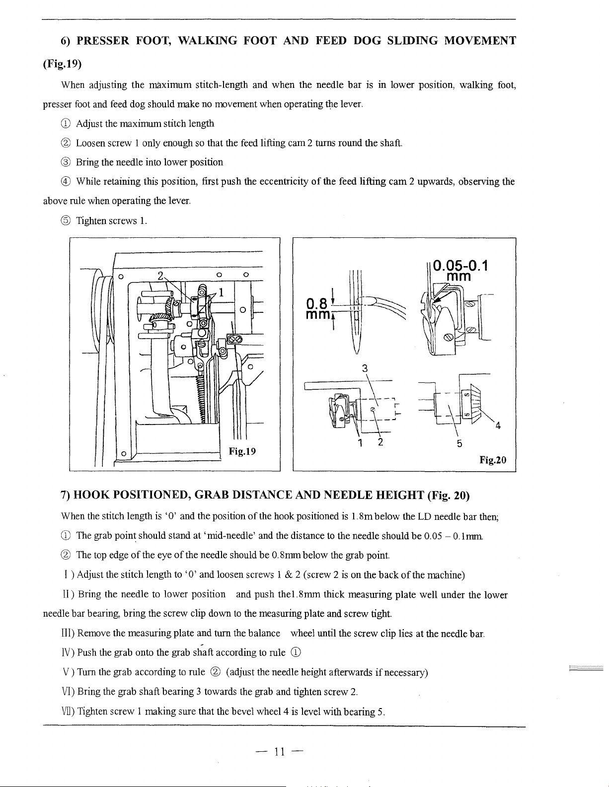
6)
(Fig.19)
PRESSER FOOT,
WALKING
FOOT
AND
FEED
DOG
SLIDING
MOVEMENT
When adjusting the
presser foot and feed
CD
Adjust the
® Loosen
screw
® Bring the needle into
maximum
dog
should
maximum
stitch length
1 only enough so
lower
make
@ While retaining this position, first
above rule
when
operating the lever.
@ Tighten screws
1.
stitch-length
no
movement
that
the feed lifting
position
push
and
when
the
when
operating the lever.
cam
the eccentricity
needle
2 turns
of
the feed
bar
round
is
in
the shaft.
lifting
3
lower
position,
cam
2 upwards, observing the
walking
0.05-0.1
mm
foot,
0
7)
HOOK
When
CD
The grab
® The top edge
POSITIONED,
the stitch length is
point
of
I ) Adjust the stitch length to
II)
Bring the
needle
bar
III) Remove the
IV)
Push the grab onto the grab
V)
Turn the grab according to
bearing,
needle
bring
measuring
'0'
and the position
should stand
the eye
to
the
of
the needle should
'0'
lower
screw
plate
=&~--~
Fig.19
GRAB DISTANCE AND
of
the
hook
at
'mid-needle'
and
loosen screws 1 & 2 (screw 2 is
position
clip
down
and
turn the
shaft
according to
rule
® (adjust the needle height afterwards
and the distance to the needle should
be
0.8mm
and
push
the1.8mm
to the measuring plate
balance
wheel until the
rule
CD
NEEDLE
positioned is
below
thick
=:}-~
~\-;-
1 2 5
HEIGHT
1.8m
below
the grab point.
on
the
back
measuring
and
screw
tight.
screw
clip lies
if
necessary)
--L~4
(Fig. 20)
the
LD
needle
be
0.05-
0.1mm
of
the machine)
plate
well
under
at
the needle bar.
bar
the
Fig.20
then;
lower
VI) Bring the grab
VII)
Tighten
screw 1 making
bearing
3 towards the grab
sure
that the
bevel
and
tighten
wheel 4 is level
-
11-
screw
with
2.
bearing
shaft
5.
Page 16
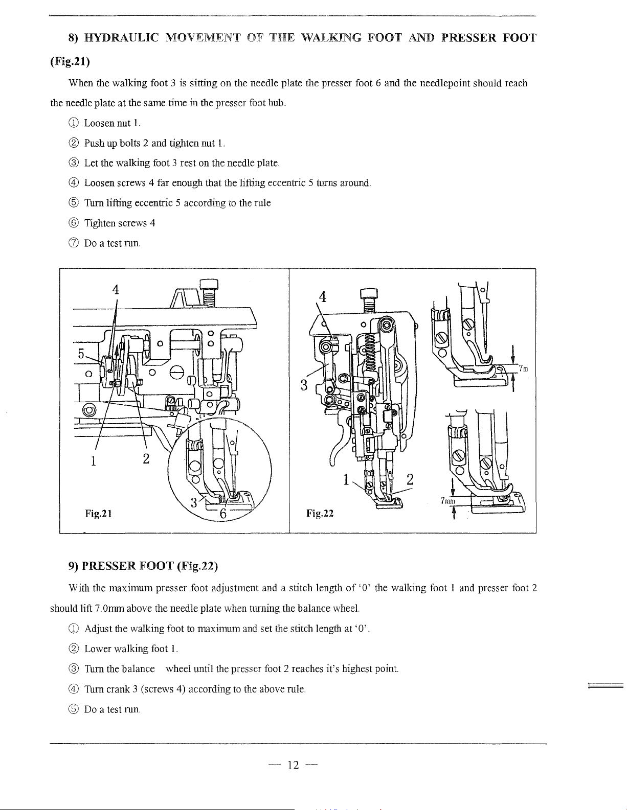
8)
(Fig.21)
HYDRAULIC
MOVEMENT
OF
THE
WALKING
FOOT
AND
PRESSER
FOOT
When the walking foot 3 is sitting
the needle plate at the same time in the presser foot hub.
CD
Loosen nut
® Push
1.
up
bolts 2 and tighten nut
on
the needle plate the presser foot 6 and the needlepoint should reach
1.
® Let the walking foot 3 rest on the needle plate.
@)
Loosen screws 4 far enough that the lifting eccentric 5 turns around.
@ Turn lifting eccentric 5 according
@ Tighten screws 4
([)
Do
a test run.
r-------------------·-,---------------------,
to
the rule
4
Fig.22
9)
PRESSER
With the maximum presser foot adjustment and a stitch length
should lift 7.0mm above the needle plate when turning the balance wheel.
CD
Adjust the walking foot
® Lower walking foot
FOOT
(Fig.22)
to
maximum and set the stitch length at
1.
of
'0'
'0'.
® Turn the balance wheel until the presser foot 2 reaches it's highest point.
@)
Turn crank 3 (screws 4) according
@
Do
a test run.
to
the above rule.
-12-
the walking foot 1 and presser foot 2
Page 17
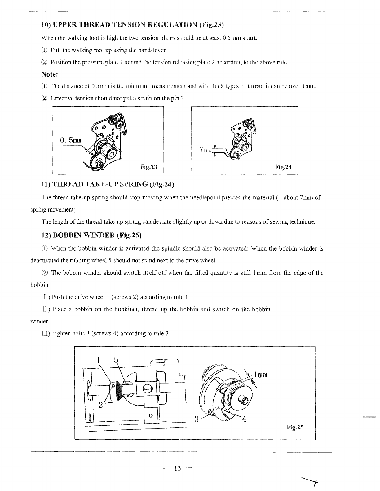
10)
UPPER
THREAD
TENSION
REGULATION
(Fig.23)
When the walking foot is high the two tension plates should
CD
Pull the walking foot up using the hand-lever.
be
at least 0.5mm apart.
® Position the pressure plate 1 behind the tension releasing plate 2 according
Note:
CD
The
distance
® Effective tension should not put a strain on the pin
of0.5mmis
the minimum measurement and 'Nith thick types
3.
0.5mm
'7mlll
Fig.23
11)
THREAD
The thread take-up spring should stop moving when the needlepoint pierces the
spring movement)
TAKE-UP
SPRING
(Fig.24)
to
the above rule.
of
thread
material(=
it
can be over
Fig.24
about 7mm
lnnn
of
of
The length
12) BOBBIN
CD
When the bobbin winder is activated the spindle should also
deactivated the rubbing wheel 5 should not stand next
® The bobbin winder should switch itself
bobbin.
I )
Push
II)
Place a bobbin on the bobbinet, thread
winder.
Ill) Tighten bolts 3 (screws 4) according
the thread take-up spring can deviate slightly up or down due
WINDER
the
drive
wheell
,-----------------------------··----------·-,
(Fig.25)
off
(screws 2) according
up
to
rule
to
reasons
be
activated: When the bobbin winder
to
the drive wheel
when the filled quantity is still 1
to
rule
l.
the bobbin and switch on the bobbin
2.
mm
of
sewing technique.
from the edge
of
is
the
'---·----------·------------------------------'
-13-
Fig.25
Page 18
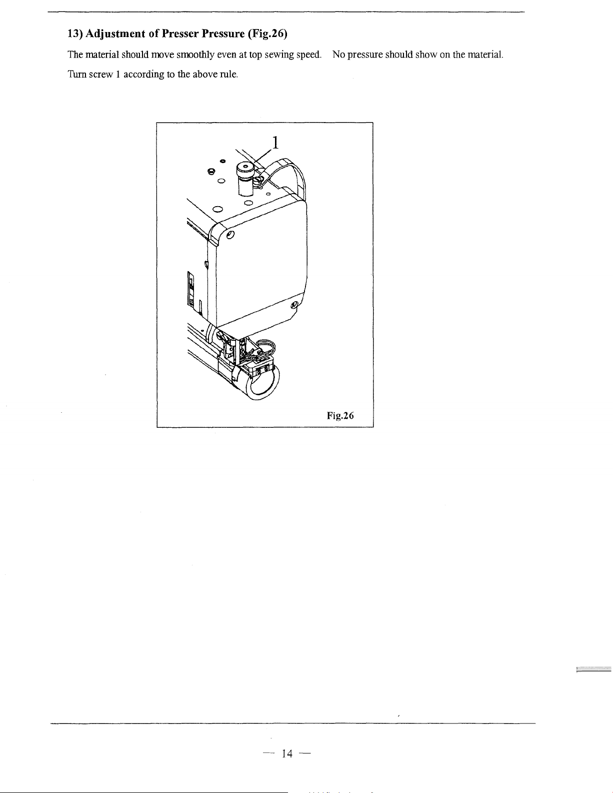
13) Adjustment
of
Presser Pressure (Fig.26)
The material should move smoothly even
Turn screw 1 according to the above rule.
at
top sewing speed. No pressure should show on the material.
1
Fig.26
-
14-
Page 19
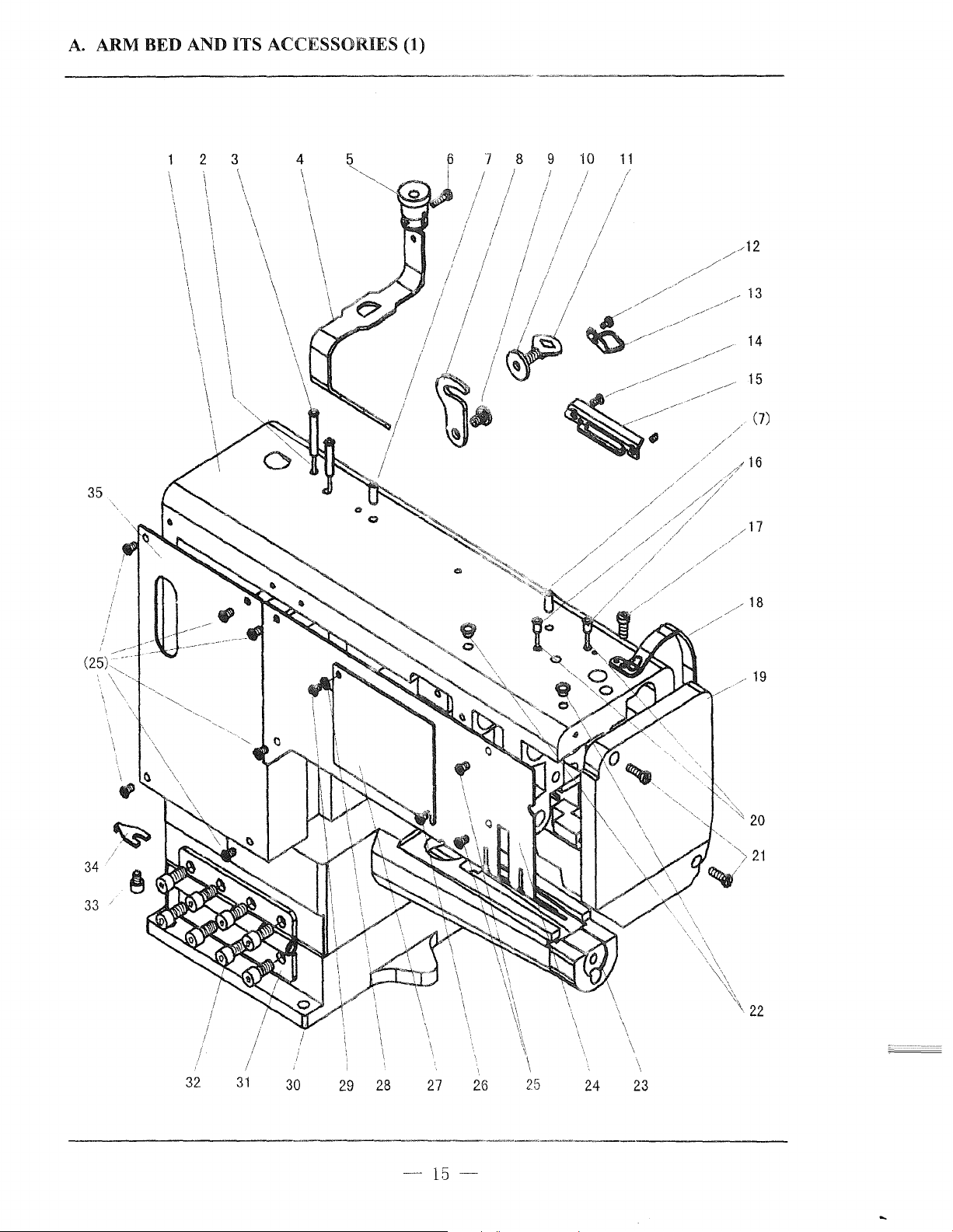
A.
ARM BED AND ITS ACCESSORIES (1)
3 4
2
6 7 8 9
/ / /
/ /
I / I
I / 1/
I
/ / I
/ I / /
' / /
I I / '
I
/1~
I
~~
1/
10
11
1/
35
34
~~
(7)
/
19
20
33
/
32
31
30
29
28
-15-
27
26
25
24
\
\
\
23
22
Page 20
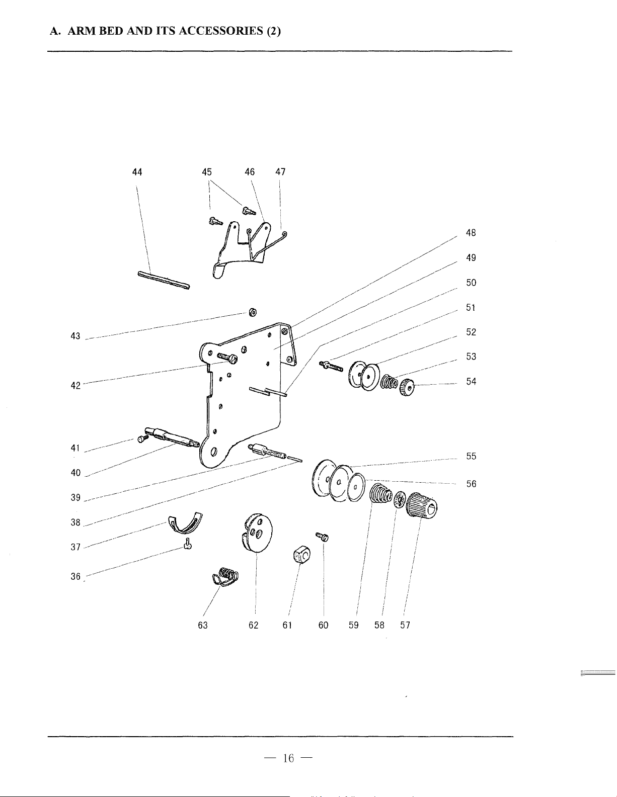
A.ARM
BED AND
ACCESSORIES (2)
_
IT_.S~------~
43
42---
41
44
I
\
\
\
\
-----
------
--~----
------
~~
~-
-------
~-----
45 46
1"'--
I""-~
!
I \
\
I
\
'~\
----@
'~
47
I
!
!
I
48
49
50
51
52
53
54
37--
~-·
63
I
I
/
fi)
~
I
62
I
I
I
i
61
-
16-
60
59 58
57
Page 21
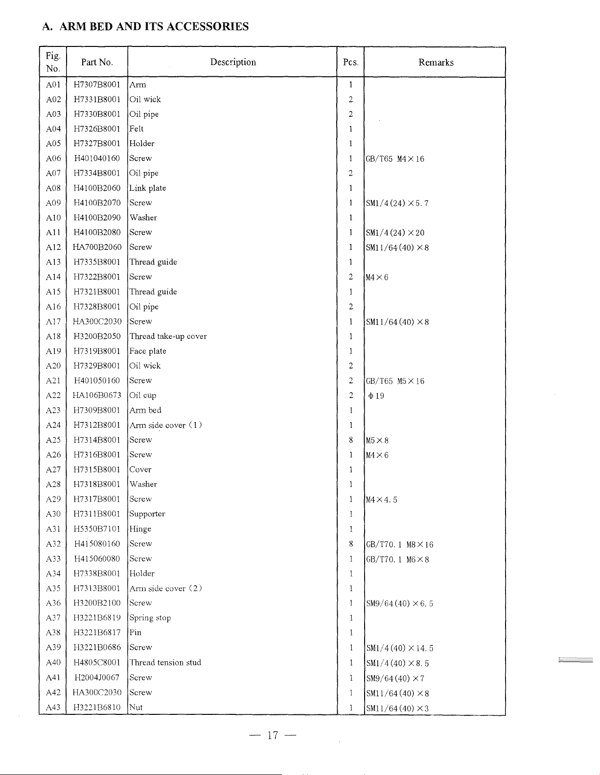
A.
ARM BED AND ITS ACCESSORIES
Fig.
No.
A01 H7307B8001
A02 H7331B8001
A03 H7330B8001
A04 H7326B8001 Felt 1
AOS
A06
A07 H7334B8001 Oil pipe 2
A08
A09
A10
All
Al2
Al3
A14
AlS
Al6
A,17
Al8
A19 H7319B8001 Face plate
A20 H7329B8001
A21
A22 HA106B0673
A23 H7309B8001
A24
A25 H7314B8001
A26
A27
A28
A29
A30
A31
A32
A33
A34
A35
A36
A37
A38 H3221B6817 Pin
A39 H3221B0686
A40 H4805C8001 Thread tension stud
A41
A42
A43 H3221B6810 Nut
Part No.
Arm
Oil wick
Oil pipe 2
H7327B8001
H401040160 Screw
H4100B2060
H4100B2070 Screw
H4100B2090
H4100B2080
HA700B2060
H7335B8001 Thread guide 1
H7322B8001
H7321B8001
H7328B8001 Oil pipe
HA300C2030 Screw
~'
H3200B2050 Thread take-up cover
H401050160 Screw
H7312B8001
H7316B8001
H7315B8001 Cover
H7318B8001
H7317B8001
H7311B8001 Supporter
H5350B7101 Hinge
H415080160
H415060080 Screw
H7338B8001 Holder
H73\3B8001
H3200B2100 Screw
H3221B6819 Spring stop
H2004J0067 Screw
HA300C2030
Holder
Link
plate 1
Washer
Screw
Screw
Screw
Thread guide
Oil wick
Oil cup
Arm
bed
Arm
side cover (
Screw
Screw
Washer
Screw
Screw
Arm
side cover (
Screw
Screw
Description
1)
2)
Pes.
1
2
1
1
GB/T65
1
SMl/4(24)
1
1
SMl/4(24)
1
SMll/64
2
M4X6
1
2
1
SMll/64(40)
1
1
2
2
GB/T65
2
<P
19
1
1
8
M5X8
1
M4X6
1
1
1
M4X4. 5
1
1
8
GB/T70. 1
1
GB/T70. 1
1
1
1
SM9/64 (40) X
1
1
1
SMl/4(40) X 14.5
1
SMl/4(40)
1
SM9/64 (40) X 7
1
SMll/64(40)
1
SMll/64(40)
M4 X 16
X5.
X20
(40) X 8
X 8
M5 X 16
MSX
M6
X 8
XS. 5
XS
X3
Remarks
7
16
6.
5
--
-
17-
Page 22
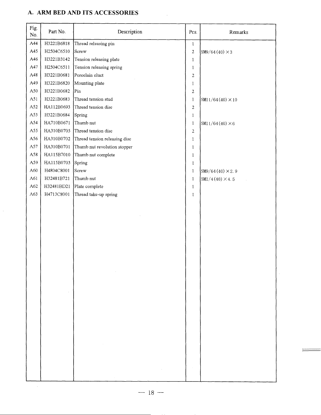
A.
ARM BED AND ITS ACCESSORIES
Fig.
No.
A44
A45
A46 H3221B3142
A47
A48
A49
A50
A51
A52
A53
A54
A55
A56
A57
A58
A59 HA115B0703
A60
A61
A62
A63
Part
No.
H3221B6818
H2504C6510
H2504C6511
H3221B0681
H3221B6820
H3221B0682
H3221B0683
HA112B0693
H3221B0684
HA710B0671
HA310B0705
HA310B0702
HA310B0701
HA115B7010
H4804C8001
H32481B721
H32481BD21
H4713C8001
Description
Thread releasing pin
Screw
Tension releasing plate
Tension releasing spring
Porcelain cluct
Mounting plate
Pin
Thread tension stud
Thread tension disc
Spring
Thumb nut
Thread tension disc
Thread tension releasing disc
Thumb nut revolution stopper
Thumb nut complete
Spring
Screw
Thumb nut
Plate complete
Thread take-up spring
Pes.
1
2
SM9/64
1
1
2
1
2
1
SM11/64(40) X
2
1
1
SM1l/64(40)
2
1
1
1
1
1
SM9/64
l
SMl/ 4
1
1
(40) X 3
(40) X
(40) X
Remarks
10
X6
2.
9
4.
5
-18-
Page 23
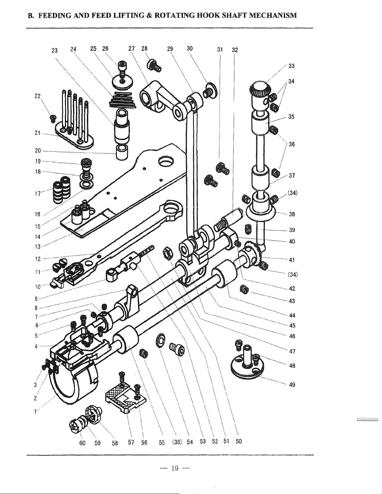
B.
FEEDING
AND
FEED LIFTING & ROTATING
HOOK
SHAFT MECHANISM
23
28
"
29
31
32
r--=--+-+------
-r-----
34
35
37
(34)
38
39
40
12
11-
3
2
-----
-----=--------::;;.7.
I
I
\
\
\
\
\
\
\
\
\
\
\
53
\
\
\
\
\
\
\
\
\
I \
\
\
\
52
~~
\ I
\
\
\
\
\ \
\
\
\
\
\
\
\
\
\
\
\
\
\
\
\
\
\
\
\
(36)
\
54
~'',
60
59 58
I
57 56
55
41
(34)
~-
-------45
46
---...._______
---------
48
\
\
\
I
\
--------
49
\
\
\
\
I
\
\
I
\
\
51
50
-19-
Page 24
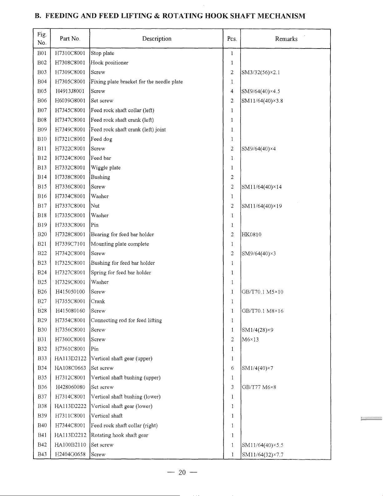
B.
FEEDING AND FEED
LIFTING
& ROTATING
HOOK
SHAFT MECHANISM
Fig.
No.
BOI
B02 H7308C800!
B03
B04 H7305C8001
B05
B06 H6039G800!
B07 H7345C8001 Feed rock shaft collar (left)
B08 H7347C8001 Feed rock shaft crank (left)
B09 H7349C800! Feed rock shaft crank (left) joint
BIO H732!C8001 Feed dog
Ell
B12 H7324C800! Feed
Bl3
B14 H7338C8001
Bl5
B!6
Bl7
Bl8
Bl9
B20
B21
B22 H7342C800!
B23
B24 H7327C8001
825
B26 H415050100
827
B28 H415080160
B29 H7354C8001 Connecting rod for feed lining
B30 H7356C8001
B31
832
B33 HAI13D2122 Vertical shaft gear (upper)
834
835 H7312C8001
B36
B37 H7314C8001 Vertical shaft bushing (lower)
B38
839
B40 H7344C8001 Feed rock shaft collar (right)
841 HA113D2212 Rotating hook shaft gear
B42
B43 H2404G0658
Part No.
H7310C8001 Stop plate
Hook
positioner
H7309C8001
H4913J8001
H7322C8001
H7332C8001
H7336C8001
H7334C8001 Washer
H7337C8001 Nut
H7335C8001 Washer
H7333C8001
H7328C8001 Bearing for feed bar holder
H7339C7101 Mounting plate complete
H7325C8001 Bushing for feed bar holder
H7329C8001 Washer
H7355C8001 Crank
H7360C8001 Screw
H7361C8001
HA108C0663 Set screw 6 SM!I4(40)x7
H428060080
HA113D2222 Vertical shaft gear (lower)
H73l!C8001
HAJOOB2110 Set screw
Screw
Fixing plate bracket for the needle plate
Screw
Set screw
Screw
bar
Wiggle plate I
Bushing
Screw 2 SM11/64(40)x14
Pin
Screw
Spring for feed bar holder
Screw
Screw
Screw 1 SM!I4(28)x9
Pin
Vertical shaft bushing (upper) I
Set
screw
Vertical shaft
Screw
Description Pes.
I
1
2
I
4 SM9/64(40)x4.5
2
1
I
I
I
2 SM9/64(40)x4
I
2
I
2
1
I
2 HK0810
1
2 SM9/64(40)x3
1
I
I
1 GB/T70.1
I
I GB/T70.1
I
2
I
I
3 GB/T77 M6x8
I
1
I
I
1
I
1
Remarks
SM3/32(56)x2.1
SM!l/64(40)x3.8
SM1!164(40)x19
M5x10
M8xJ6
M6x13
SMJ!I64(40)x5.5
SM11164(32)x7. 7
-20-
Page 25
B.
FEEDING AND FEED
LIFTING
& ROTATING
HOOK
SHAFT MECHANISM
Fig.
No.
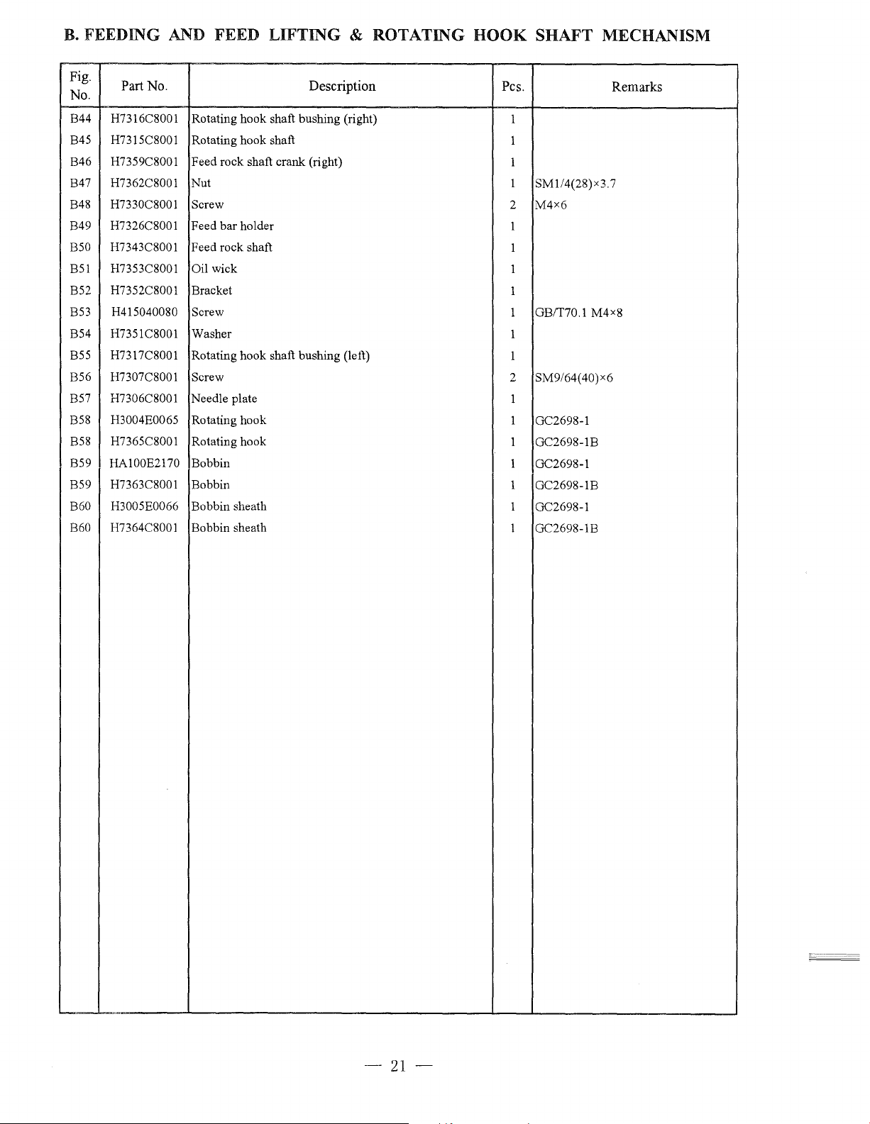
B44 H7316C8001 Rotating hook shaft bushing (right)
B45 H7315C8001 Rotating hook shaft
B46 H7359C8001 Feed rock shaft crank (right)
B47 H7362C8001 Nut
B48 H7330C8001
B49 H7326C8001 Feed bar holder
B50 H7343C8001
B51
B52
B53 H415040080
B54 H7351C8001 Washer
B55 H7317C8001
B56 H7307C8001
B57 H7306C8001 Needle plate
B58 H3004E0065 Rotating hook
B58 H7365C8001 Rotating hook
B59
B59 H7363C8001 Bobbin
B60 H3005E0066 Bobbin sheath
B60 H7364C8001 Bobbin sheath
Part No. Description
Screw
Feed rock shaft
H7353C8001 Oil wick
H7352C8001 Bracket
Screw
Rotating hook shaft bushing
Screw
HA100E2170 Bobbin
(left)
Pes.
1
1
1
1
SM1/4(28)x3.7
M4x6
2
1
1
1
1
1 GB!T70.1 M4x8
1
1
2 SM9/64(40)x6
1
1
GC2698-1
1 GC2698-1B
1 GC2698-1
1 GC2698-1B
1
GC2698-1
1 GC2698-1B
Remarks
'"
-21-
Page 26

C. ARM SHAFT
MECHANISM
20 -
19
16
15
14
22
23
\
\
I
i
24
'·
25
26
27
I
!
28
I
29
30
10---~~
9
---
----,(_,__...._
(7) //\i!
//
---------
8/
--------~1
----------
7
_/"
I
6
I
~-~
---~----
-----
.......
_
....._
__
35
_
36
37
---
------·----------
////
I
i
I
-------
- -
- 38
I
5
4
3
2
-22-
Page 27
C ARM SHAFT
MECHANISM
Fig.
No.
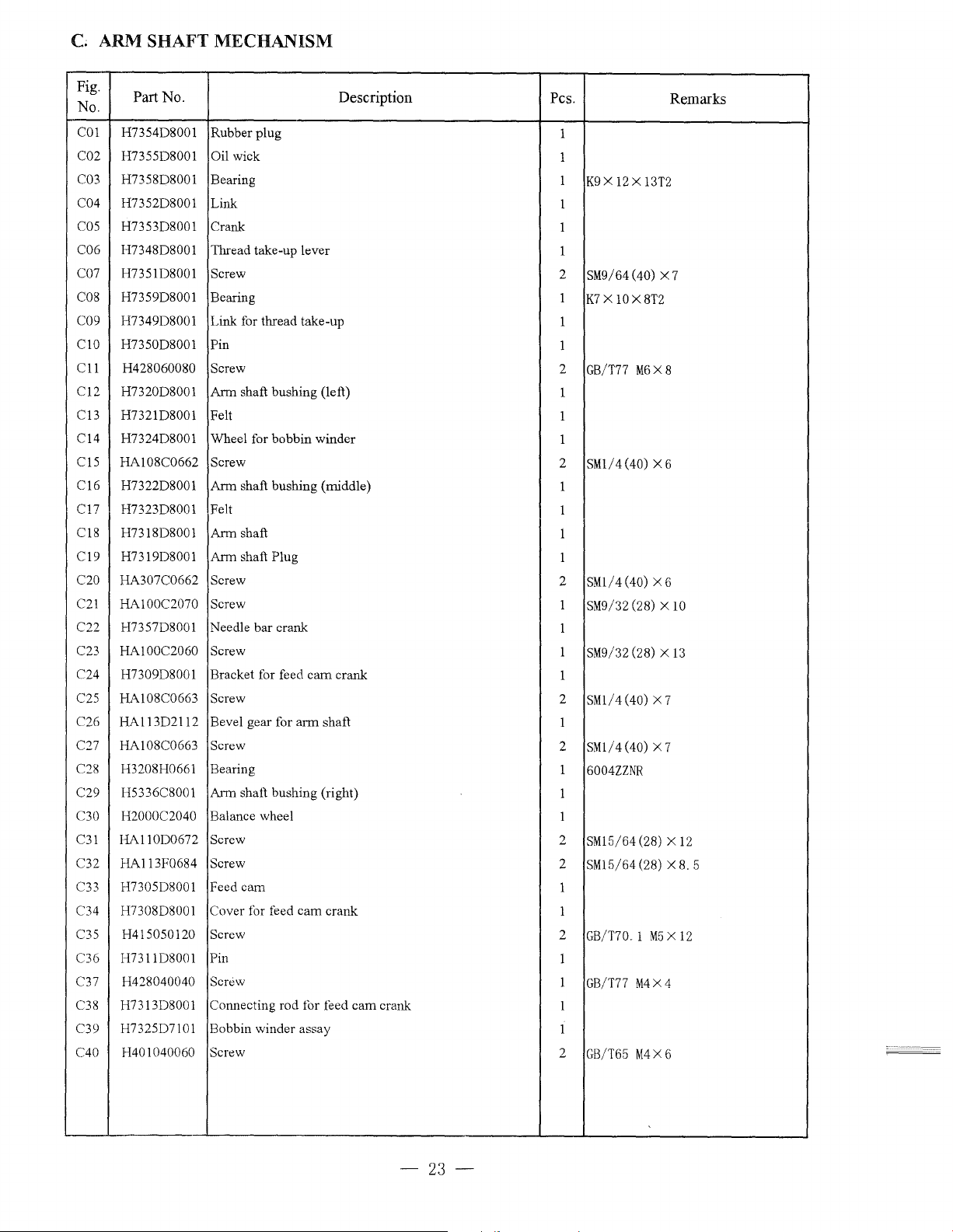
COl H7354D8001
C02 H7355D8001 Oil wick
C03 H7358D8001 Bearing
C04 H7352D8001
cos
C06 H7348D8001
C07 H7351D8001
C08 H7359D8001 Bearing
C09
ClO H7350D8001 Pin
C11
C12
C13
C14
C15
C16
Cl7
C18
Cl9
C20
C21
C22 H7357D8001 Needle bar crank
C23
C24
C25
C26 HA113D2112 Bevel gear for
C27
C28 H3208H0661 Bearing
C29
C30 H2000C2040 Balance wheel
C31
C32 HA113F0684 Screw
C33
C34
C35
C36 H7311D8001 Pin
C37
C38
C39
C40
Part
No.
Rubber plug
Link
H7353D8001 Crank
Thread take-up lever
Screw
H7349D8001
H428060080 Screw
H7320D8001
H7321D8001 Felt
H7324D8001 Wheel for bobbin winder
HA108C0662
H7322D8001
H7323D8001 Felt
H7318D8001
H7319D8001
HA307C0662 Screw
HA100C2070 Screw
HA100C2060 Screw
H7309D8001
HA108C0663 Screw
HA108C0663 Screw
H5336C8001
HA110D0672 Screw
H7305D8001 Feed
H7308D8001 Cover for feed
H415050120 Screw
H428040040
H7313D8001
H7325D7101
H401040060
Link for thread take-up
Arm
shaft bushing (left)
Screw
Arm
shaft bushing (middle)
Arm shaft
Arm
shaft Plug
Bracket for feed
arm
Arm shaft bushing (right)
cam
cam
Screw
Connecting rod for feed
Bobbin winder assay
Screw
Description
cam
crank
shaft
crank
cam
crank
Pes.
1
1
1
K9X12Xl3T2
1
1
1
2
SM9/64 (40) X 7
1
K7 X 10X8T2
1
1
2
GB/T77
1
1
1
2
SMl/ 4 (40) X 6
1
1
1
1
2
SMl/ 4 (40) X 6
1
SM9/32 (28) X
1
1
SM9/32 (28) X
1
2
SMl/ 4 (40) X 7
1
2
SMl/ 4 (40) X 7
1
6004ZZNR
1
1
2
SM15/64 (28) X
2
SM15/64 (28) X
1
1
2
GB/T70. 1
1
1
GB/T77
1
1
2
GB/T65
M6X8
M5 X 12
M4X4
M4X
Remarks
10
13
12
8.
5
6
-23-
Page 28

D.
STITCH REGULATOR MECHANISM
------
---- 2
---
----4
- 5
---- 6
3
17 16
15
14
13
12
8
------~----
--------
---------
------
9
1 0
_11
-24-
Page 29

D. STITCH REGULATOR MECHANISM
Fig.
No.
DOl
Part No.
Description Pes.
H7305E8001 Bracket for stitch length plate
D02 H7307E8001 Stitch length plate
H415060160
D03
D04
DOS
H7315E8001
H7313E8001
Screw 2
Guide bushing
Spring
D06 H7310E7101 Stitch length regulating nut assay
D07 H7314E8001
H7312E8001
D08
Washer 1
Stud
D09 H4100F2070 Screw
DlO H7325E8001 Cover
H7326E8001 Screw
Dll
Dl2
H7316E8001 Feed regulator screw bar
D13
H7323E8001
Dl4
H7318E8001 Setting frame
H7324E8001
Dl5
Dl6
H7322E8001 Screw 1
H7319E7101
D17
Spring
Guide bushing 1
Pin 1
1
1
GB/T70. 1
1
1
1
1
M6X60
2
SM9/64
(40) X 7
1
2
M5 X 7.
5
1
1
1
SM15/64(40) X7. 5
Remarks
M6 X 16
-25-
-""-~"--
~
--------
----------
Page 30

E.
PRESSER
FOOT
MECHANISM
2 3 4 5
6
7
i
I
I
23 22
21
19 18
--
-
/12
/
/
/
/
/
Q/
//13
~
~------
-
///15
t
rrf}
~
17
..
//
11
J4
16
-26-
Page 31
E.
PRESSER FOOT MECHANISM
Fig.
No.
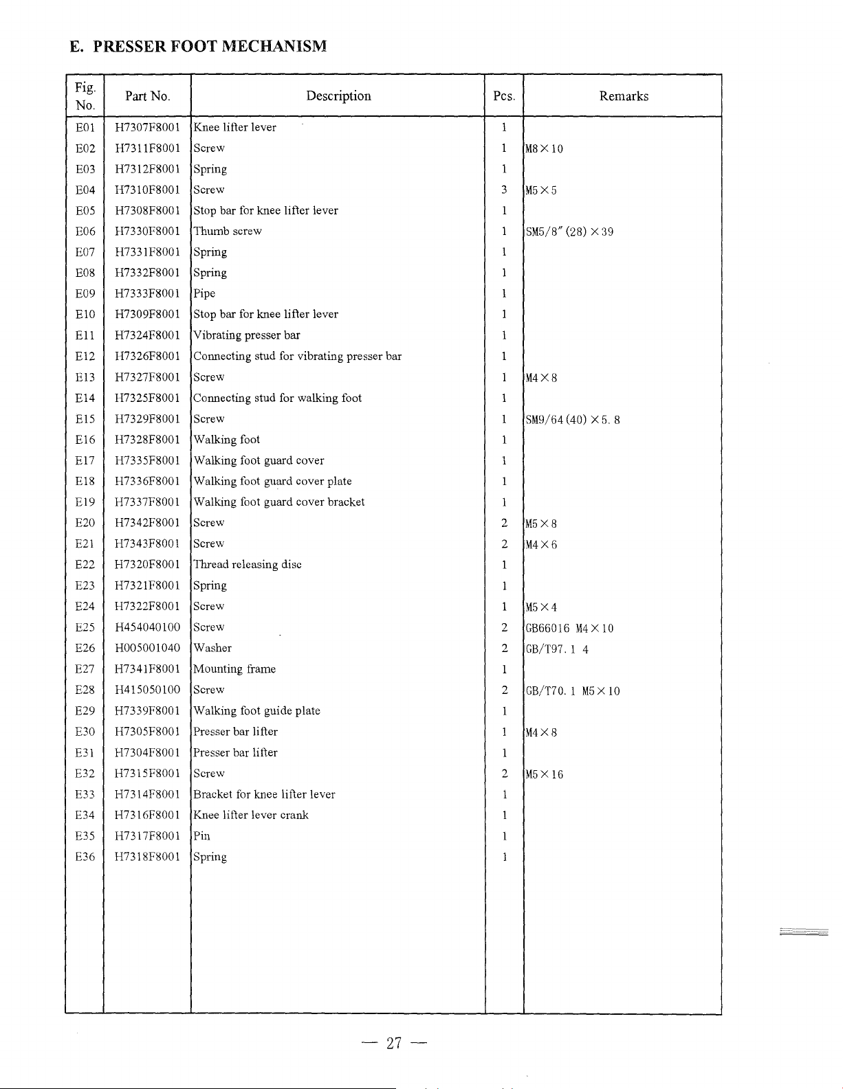
EOl
E02 H7311F8001
E03
E04
E05
E06
E07
E08
E09
ElO
Ell
El2
El3
El4
El5
El6
El7
El8
E19 H7337F8001 Walking foot guard cover bracket
E20
E21
E22
E23
E24
E25
E26 H005001040 Washer
E27 H7341F8001 Mounting frame
E28
E29 H7339F8001 Walking foot guide plate
E30
E31
E32
E33
E34
E35
E36
Part No. Description Pes. Remarks
H7307F8001
H7312F8001
H7310F8001
H7308F8001
H7330F8001
H7331F8001
H7332F8001 Spring
H7333F8001 Pipe
H7309F8001
H7324F8001 Vibrating presser
H7326F8001
H7327F8001 Screw
H7325F8001 Connecting stud for walking foot
H7329F8001 Screw
H7328F8001
H7335F8001 Walking foot guard cover
H7336F8001 Walking foot guard cover plate
H7342F8001 Screw
H7343F8001 Screw
H7320F8001 Thread releasing disc
H7321F8001 Spring
H7322F8001 Screw
H454040100
H415050100
H7305F8001 Presser
H7304F8001 Presser bar lifter
H7315F8001 Screw
H7314F8001 Bracket for knee lifter lever
H7316F8001 Knee lifter lever crank
H7317F8001 Pin
H7318F8001
Knee lifter lever 1
Screw 1
Spring
Screw 3
Stop bar for knee lifter lever 1
Thumb screw
Spring
Stop
bar
for knee lifter lever
bar
Connecting stud for vibrating presser bar
Walking foot
Screw
Screw
bar
lifter
Spring
M8X
10
1
M5X5
1
SM5/8" (28) X 39
1
1
1
1
1
1
1
M4X8
1
1
SM9/64 (40) X
1
1
1
1
2
M5X8
2
M4X6
1
1
1
M5X4
2
GB66016
2
GB/T97. 1 4
1
2
GB/T70. 1
1
1
M4X8
1
2
M5X
16
1
1
1
1
5.
M4 X 10
M5 X 10
8
-27-
Page 32
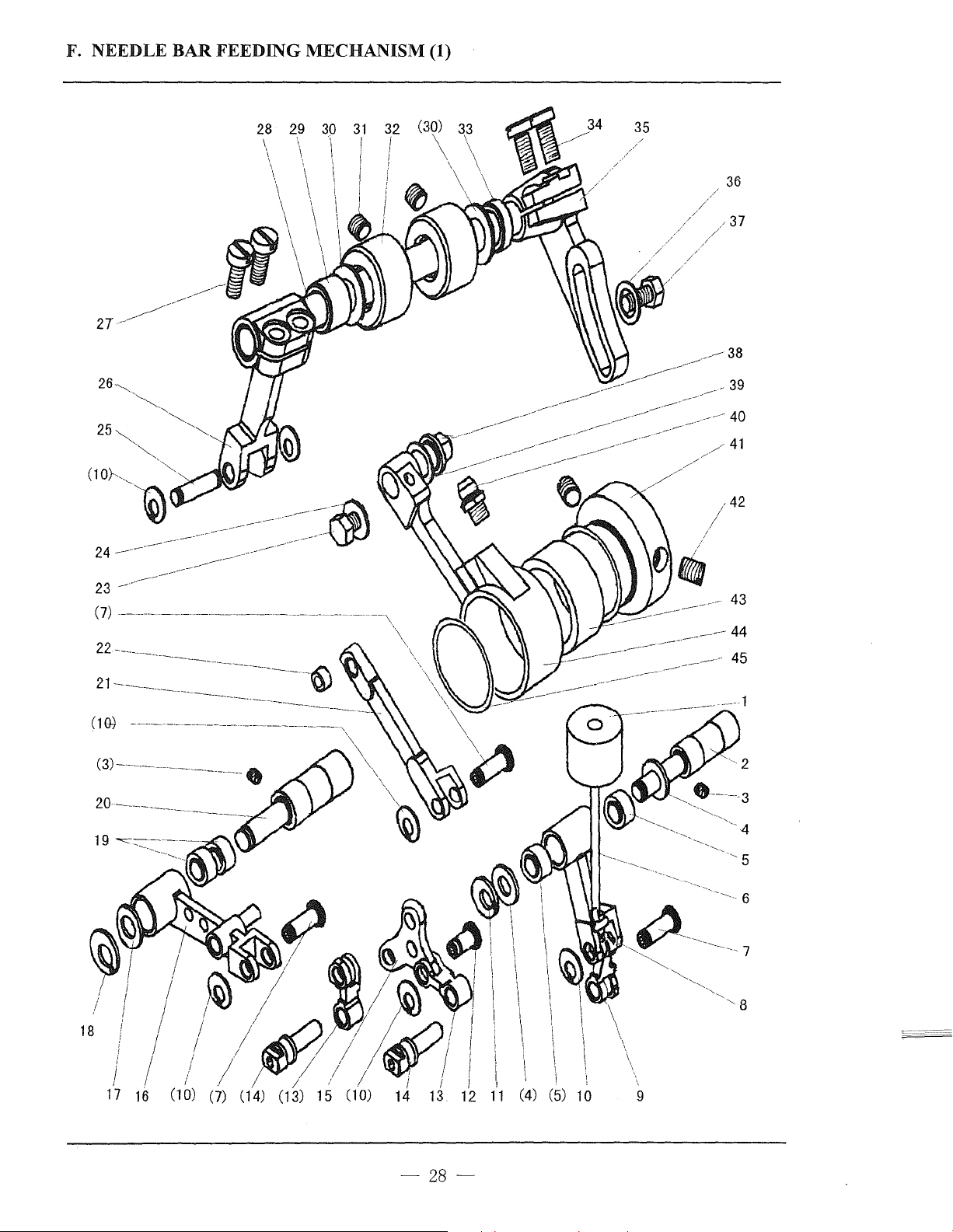
F. NEEDLE BAR
FEEDING
MECHANISM (1)
28 29 30
32
I
I
(30) 33
\ \
\ \
\ \
31
'!
I I
35
-~
/------38
---
-----
----~
-~-
-
---
/41
36
- 39
40
/42
( 1
Qj --------
(3)-------------------.
20
~-----
i
I
I
;
I
I
18
I
I I
I
I
I
I
I
16
-----------
~---
-----------------------------,
I
I
----
-6)
--------
I
/
15
\\_
\
\
\)
12
I
I
!
I,
11
(5) 10
43
45
5
9
-28-
Page 33
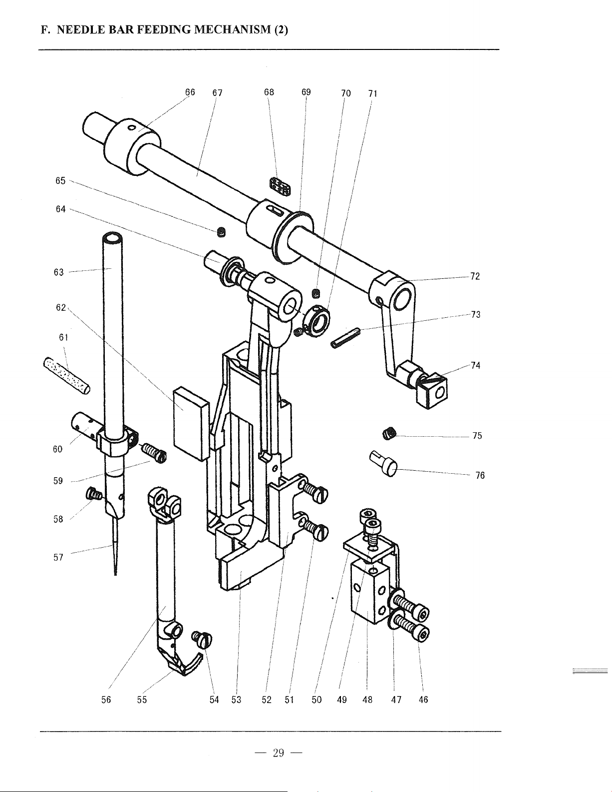
F. NEEDLE BAR FEEDING MECHANISM (2)
63
.\
65
62
61
----------
------
'
'
66
/
/
/
/
/
--
67
68
I
69
i
I
I
'
\
\
I
I
I
I
!
!
70
71
-----------------
-------73
---
____
72
.------74
'
60
59
57
-
----
56
52
51
50
49
·-------------
~-------------------
I
\
'
'
·,
48 4 7
46
75
76
-29-
Page 34
F. NEEDLE BAR
FEEDING
MECHANISM
Fig.
No.
FOI
F02 H7361G8001
F03
F04 H7362G8001 Washer
FOS
F06 H7356G7101 Spring guide bar
F07 H7337G8001
F08
F09 H7355G8001 Connecting rod 1
FlO H007009050 Stop ring 6
Fll
F12 H7335G8001
F13
F14 H7334G8001 Slide block 2
F15
F16 H7338G7101 Connecting rod complete 1
F17
F18
F19
F20 H7341G8001
F21
F22
F23 H453050080 Screw 1
F24 H7314G8001 Washer
F25 H7344G8001
F26 H7346G8001 Connecting rod 1
F27 H7377G8001 Screw 2
F28 ·
F29
F30
F31
F32 H7348G7101 Bushing for upper feed lifting rock shaft 2
F33
F34
F35
F36
F37
F38 H7313G8001
F39
F40 HD00001060 Oil cup 1
F4l
F42 H455060080
F43
Part No.
H7359G8001 Felt
Pin
H428060080 Screw
H7365G8001 Bearing 2
Pin
H7360G8001 Connecting rod 1
H007009060 Stop ring 1
Pin
H7333G8001 Connecting rod 2
H7336G8001
H7342G8001 Washer 1
H007009070 Stop ring 1
H7359D8001 Bearing 2
H7343G8001 Connecting rod 1
H7376G8001 Bearing 1
'"
H7347G8001 Upper
H7352G8001 Bushing (left) 1
H7353G8001 Washer (left) 2
H428060050 Screw
H7354G8001
H7312G8001 Screw
H7311G8001 Regulating crank 1
H005001050 Washer 1
Hl02050100 Screw 1
H7315G8001 Washer
H7305G8001 Cam for presser foot lifting
H7316G8001
Crank
Pin
Pin 1
feed lifting rock shaft 1
Bushing (right) 1
Pin
Screw
Bearing
Description Pes.
1
1
2
GB/T77
2
K6X 9X8T2
1
3
GB/T894. 1 5
GB/T894. 1 6
1
1
GB/T894. 1 7
K7
X lOX
1
K5X8X8T2
GB30004
1
M5X
2
GB/T77
2
M5
X 1 L 7
GB/T97.
GB/T5781
1
1
JB/T7940. l
1
2
GB7403l M6X8
1
K24X29Xl3
12
M6X
8T2
M5
M6X5
1 5
M5X
Remarks
8
X 8
10
M6
-30-
\_}
Page 35
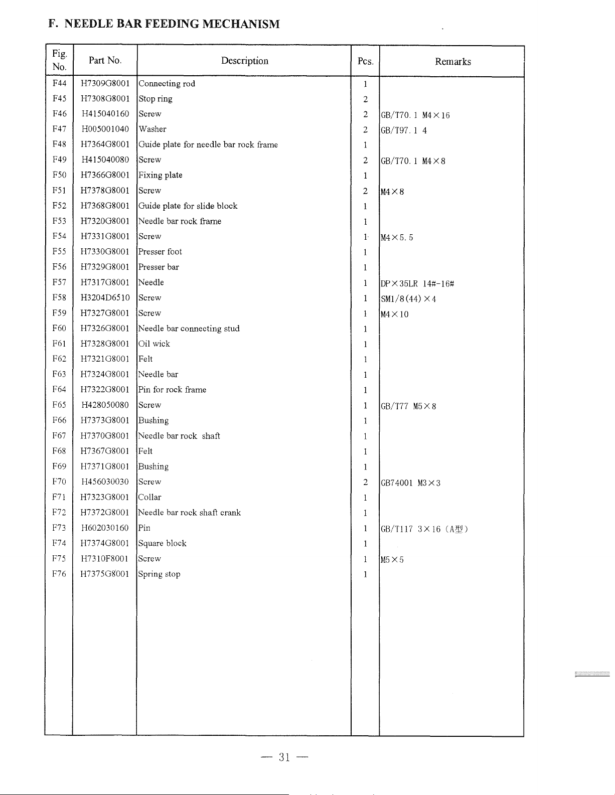
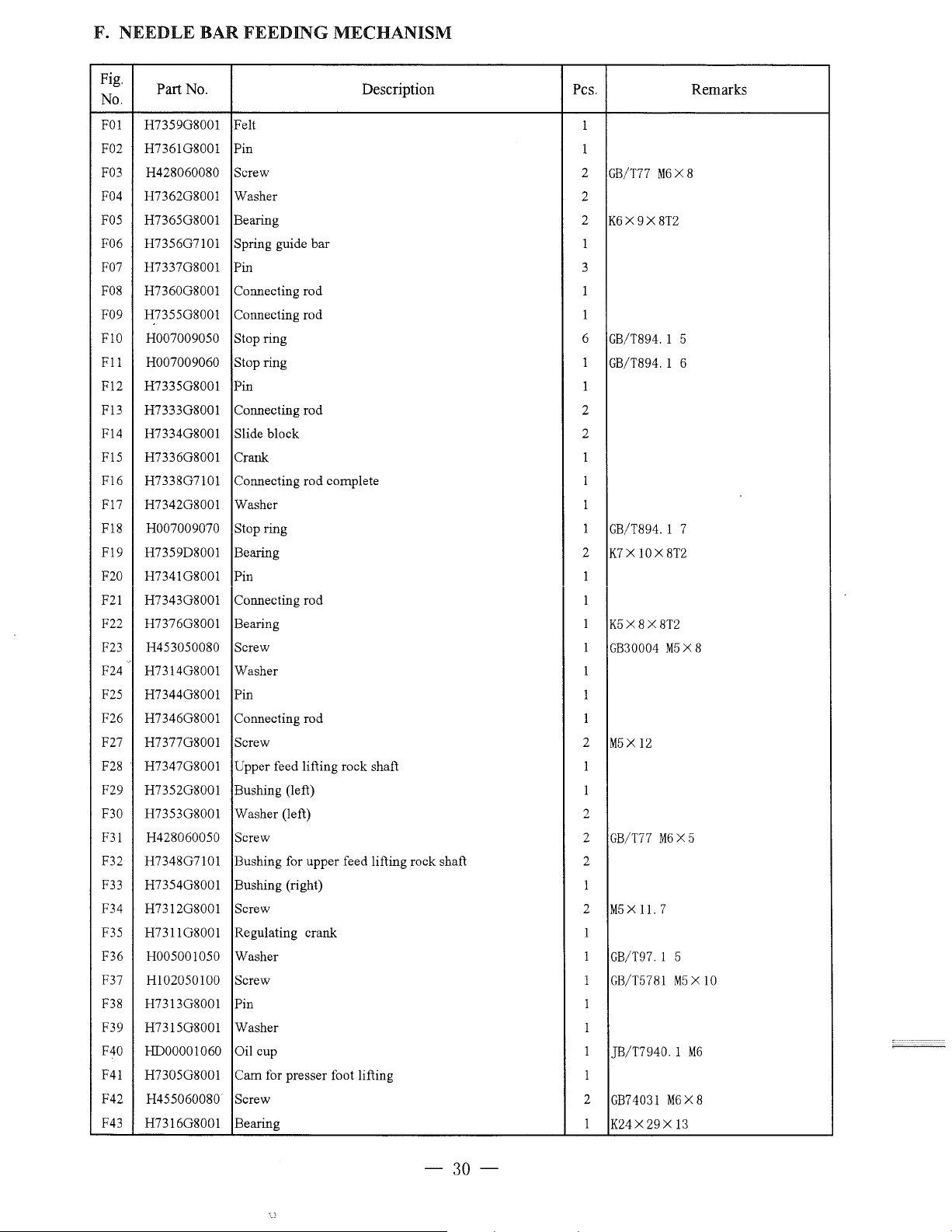
F. NEEDLE BAR FEEDING MECHANISM
Fig.
No.
F44 H7309G8001
F45
F46
F47
F48
F49
FSO
F51
F52 H7368G8001
F53
F54
FSS
F56
F57
F58
F59 H7327G8001
F60 H7326G8001
F61 H7328G8001
F62
F63
F64
F65
F66
F67
F68
F69
F70 H456030030 Screw
F7!
F72
F73
F74
F75
F76
Part
No.
Connecting rod
H7308G8001
H415040160
H005001040 Washer
H7364G8001
H415040080 Screw
H7366G8001 Fixing plate
H7378G8001 Screw
H7320G8001 Needle bar rock frame
H7331G8001
H7330G8001
H7329G8001
H7317G8001 Needle
H3204D6510
H7321G8001 Felt
H7324G8001
H7322G8001
H428050080 Screw
H7373G8001 Bushing
H7370G8001 Needle bar rock shaft
H7367G8001
H7371G8001 Bushing
H7323G8001
H7372G8001 Needle bar rock shaft crank
H602030160 Pin
H7374G8001 Square block
H7310F8001 Screw
H7375G8001 Spring stop
ring
Stop
Screw
Guide plate for needle
Guide plate for slide block
Screw
foot
Presser
Presser bar
Screw
Screw
Needle bar connecting stud
Oil wick
Needle bar
Pin for rock frame
Felt
Collar
Description
bar
rock frame
Pes.
1
2
2
GB/T70. 1
2
GB/T97. 1 4
1
2
GB/T70.1 M4X8
1
2
M4X8
1
1
1
M4X5. 5
1
1
1
DP
X 3
1
SM1/8 (44) X 4
1
M4X
1
1
1
1
1
1
GB/T77
1
1
1
1
2
GB7
1
1
1
GB/Tl1 7 3 X
1
1
M5X5
I
5LR
10
4001
M5
M3
Remarks
M4X
141:1-1
X 8
X 3
16
16
61:1
(A~
)
-31-
Page 36
G.
A
CCESSORIES
g-
8
14
15
16
17
18
~
2-----------
31
30
----23
__...--
24
25
-r--~-:rs-
J -
29
28
___
--------
26
27
:::_
-----=--
--
-32-
Page 37
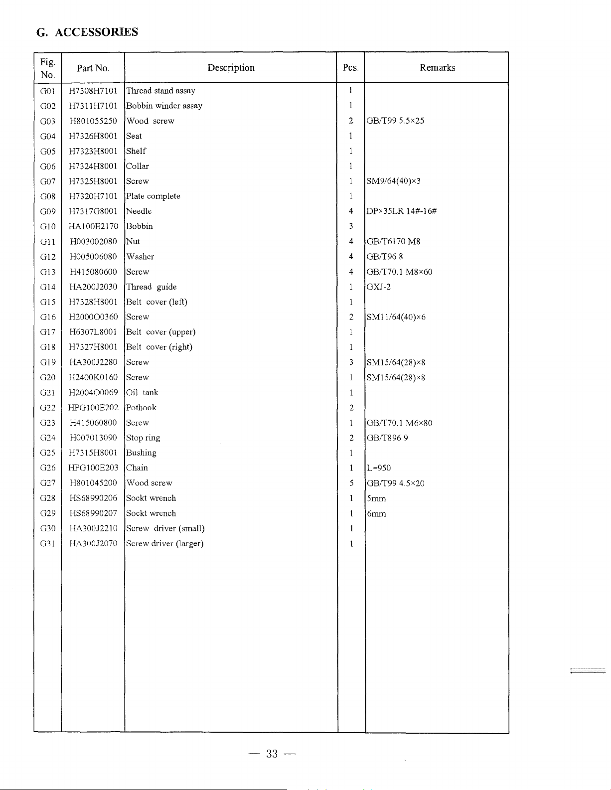
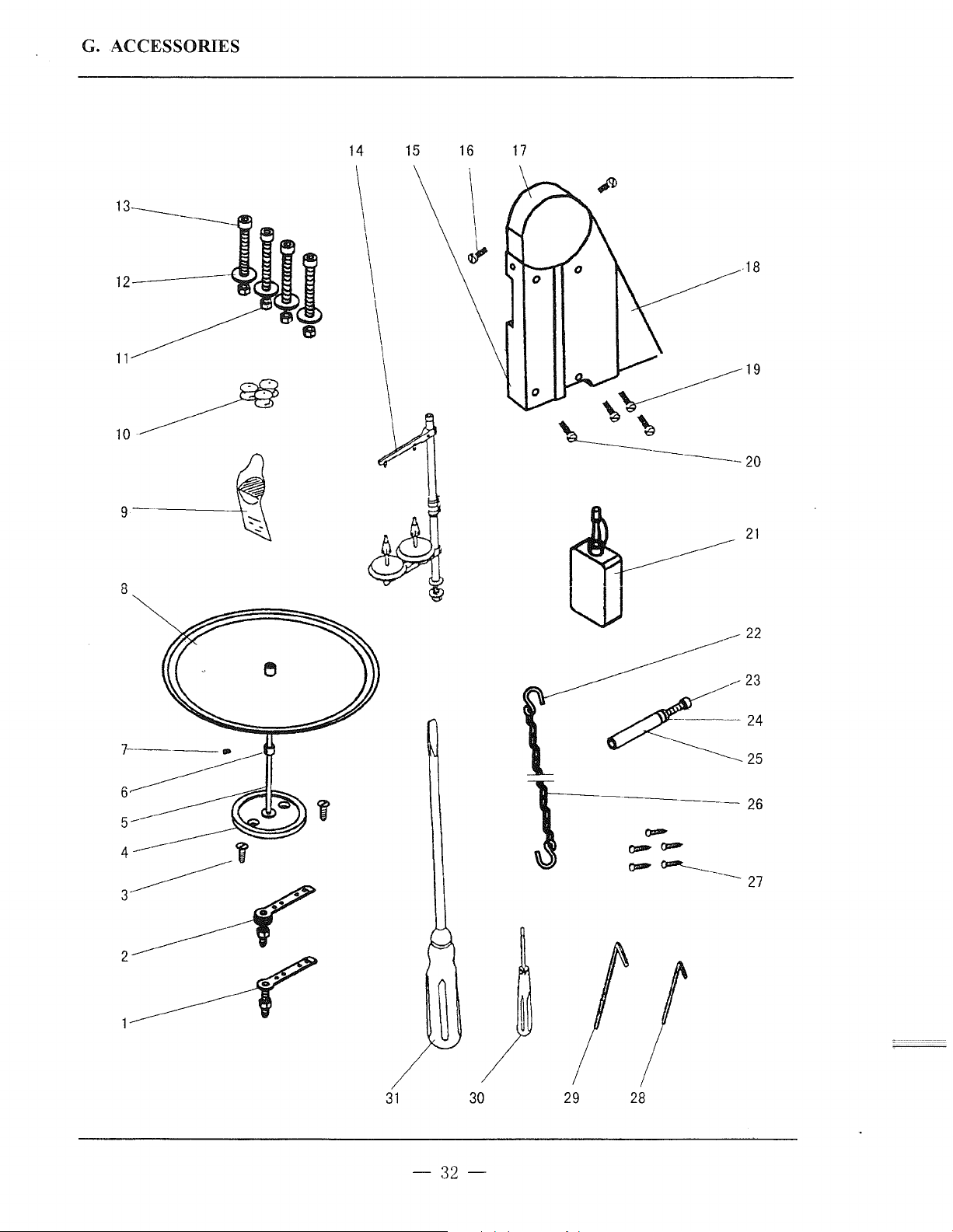
G.
ACCESSORIES
Fig.
No.
001
002
003
004
005
006
007
008
009
GlO
G11
G12
013
G14
015
016
G17 H6307L8001 Belt cover (upper)
G18
019
020
021
022
023
024
025
026
027
028
029
030
G31
Part No.
H7308H7101
H7311H7101
H801055250
H7326H8001 Seat
H7323H8001
H7324H8001
H7325H8001 Screw
H7320H7101
H731708001
HA100E2170 Bobbin
H003002080 Nut 4 OB/T6170 M8
H005006080 Washer
H415080600
HA200J2030 Thread guide 1 OXJ-2
H7328H8001
H200000360 Screw
H7327H8001 Belt cover (right)
HA300J2280 Screw
H2400K0160
H200400069 Oil tank
HP0100E202
H415060800 Screw
H007013090 Stop ring
H7315H8001 Bushing
HP0100E203 Chain
H801045200
HS68990206 Sockt wrench
HS68990207 Sockt wrench
HA300J2210 Screw driver (small)
HA300J2070 Screw driver (larger)
Thread stand assay
Bobbin winder assay
Wood screw 2
Shelf
Collar 1
Plate
complete 1
Needle 4 DPx35LR 14#-16#
Screw
Belt cover (left)
Screw
Pothook
Wood screw
Description
Pes. Remarks
1
1
1
1
1 SM9/64(40)x3
3
4
4
1
2
1
1
3 SM15/64(28)x8
1 SM15/64(28)x8
1
2
1 OB/T70.1 M6x8Q
2
1
1
5
1
1
1
1
OB/T99 5.5x25
OB/T96 8
OB/T70.1 M8x6Q
SM11/64(40)x6
OB/T896 9
L=950
OB/T99 4.5x20
5mm
6mm
-33-
Page 38

Page 39

Page 40
SHANGHAI HUIGONG
N0.3
SEWING MACHINE FACTORY
ADD: 1418,
Yishan
Road,
Shanghai,
China
Zip Code: 201103
Overseas
Business:
TEL:
86-21-64853303 FAX: 86-21-64854304
E-mail:highlead@online.sh.cn http://www.highlead.com.cn
The
description
covered
in
this
manual
is
subject
to
change
for
improvement
of
the
commodity
without
2003.12.
notice
Printed
 Loading...