

Page 1
I
HIGH
LEAD
GC24698-5RI-5L/-6
l
Post-bed
lockstitch
Instruction
heavy
sewing
duty
Parts
compound
machine
Manual
Catalog
feed
(20)
SHANGHAI HUIGONG
N0.3
SEWING MACHINE FACTORY
Page 2
----- CONTENTS-----
!.OPERATING INSTRUCTION ......................
UP
THE
2.SETTING
3.CAUTION BEFORE STARTING
4.0ILING········
S.NEEDLE··········· ........
6.THREAD···········"·······
?.WINDING
THE
MACHINE .....................................
THE
······
···
· ..........................................
.........
......
.....................
..
······
..
············································
LOWER
THREAD
ON
OPERATION·· .. ········· .......................................................................... 1
..........
.............
..........
...
..............................
...
........................................................................................................... 2
..
··· ...................................................................................... 3
THE
BOBBIN ................................................................................... 3
...
..................
............................................................................... 1
...
....................................................................... 2
........................................................ 1
. . .
8.THREADING
9.
Iill
GULATING
10. ADJUSTMENT
11
. ADJUSTMENT
12
.REVERSE STITCHING ........................................................................................................................................ 5
13.IillLATIVE POSITION
NEEDLE
14.
ADJUSTMENT
15. TIMING
THE
NEEDLE .....................................................
TilE
TH:READ TENSIONS···
OF
OF
THE
AND
THE
THE
BET'\VEEN
THE
STITCH
PRESSURE
OF
NEEDLE
HEIGHT
THE
HOOK
··
................................................................................................... 4
LENGTH
.............
VIBRATING AND
HOLE
OF
THE
AND
OF
FEED
THE
..............
..............
THE
FEEDER .............
DOG .....
NEEDLE ................
......
...................................................................... 3
..................................................................................... 4
...
. ::···
·· .........
....
..........
.......
............
LIFfiNG
............................................................................... 6
PRESSER
....
.........................................................
....
............................................................ 6
BAR, ALSO,
....
.........
...................
OF
THE
...
5
6
16.ADJUSTMENT
17.ADJUSTMENT
18.TIMING
19
.ADJUSTMENT
20.ADJUSTMENT
21.REPLACEMENT
22.TO
OFTHE
RE-ENGAGE
PARTS CATAL
A.ARM BED
B.
ARM SHAFT MECHANISM ..............................................................
C.PRESSER
.S
TITCH REGULATOR AND
D
E.HOOK SADDLE MECHANISM(GC24698-6)··
F.HOOK SADDLE MECHANISM(GC24698-SL)·········· ..
GHOOK
H. THREAD
SADDLE MECHANISM(G·C24698-SR) ............................................................................................... 29
TENSION REGULATOR MECHANISM ..........
OF
OF
VffiRATINGAND LIFTING PRESSER
OF
OFTHE
OF
THE
OG
AA'D IT'S
FOOT
MECHANISM .......................
BOBBIN CASE OPENER ................................................................................................. 7
THE
HEIGHT
THE
CLEARANCE
THREAD
THE
CONNECTION BELT ........................................................................................ 10
SAFETY CLUT
ACCESSORIES·····-·· ...................................................................................................... 12
OF
CONTROLLER
FEED
ROCKING MECHANISM ................................................................. 20
THE
PRESSER
FOR
THE
CH
.....................................................................................................
...
........................
......................
FEET
VIBRATING AND
SPRING ................................................................... 10
··
.. ····· ........................................................................... 26
..................................................................... 8
FEET
............................................................... 8
LIFTING
....
............................................................. 14
......
................................................................ 17
...
....................
......
.......................................................
...
...................
PRESSER
,.
.............
...............
FEET· ... 9
11
...
........... 23
32
!.SPECIAL PARTS
J.SPECIAL PARTS F
K.ACCESSORIES······ ................................................................................................................................................ 38
FOR
GC24698-5L/5R······· .................................................................................................
OR
GC24698-6 ......................................
...
....................................................................
...
.......
.. 35
37
Page 3
l.OP
ERATING INSTRUCTIONS
HIGHL
EAD GC24698-5L, GC24698-5R, GC24698-6
SERIES MODEL
This
is
a guide to use
high speed for heavy-duty materials sewing machine with compound feed and walk i
under the best condition.
Pl
ease read this guide
of
H!GHLEAD GC24698-5L, GC24698-
thor
oughly so
that
you may expect good
5R,
GC24698-6 series model long-arm
perform
Specifications
SING
LE
NEEDLE
GC
24698-5LI5R
MAX.
SPEED
MAX.
STITCI-
PRESSER FOO
CLEAI?i\~CE
N
EEDL
E
13013BIN
W
ORKING
13ED
DIMENSION
!'OWER
M
OTOR PULLE
(s.p.m.) 1,
1 (
rnm
)
S
IZE
SPACE
ll
EQU 1
T !land L
P
(mm)
(mm)
RED
Y
DIA
cda
(W)
.
iJ
l 1
(mm
)
.i
ter
ft
(rnm)
er (mm
)
DY
<I>
70
I
~>
60
(50 I 60H
200
10
20
28
X 3
(sanda
508 X 15
846
X
75
0\V SERVO MOTOR
z)
rd
No.
230
<I>
ng
foot feeding mechanism,
ance.
T
WO
NEEDLE
GC24698
24-26)
-6
3
70
I
cl>
60
(50 I 60
Hz)
USE
FOR
Tent, Sailcloth, Rubberized,
Lea
ther, Etc.
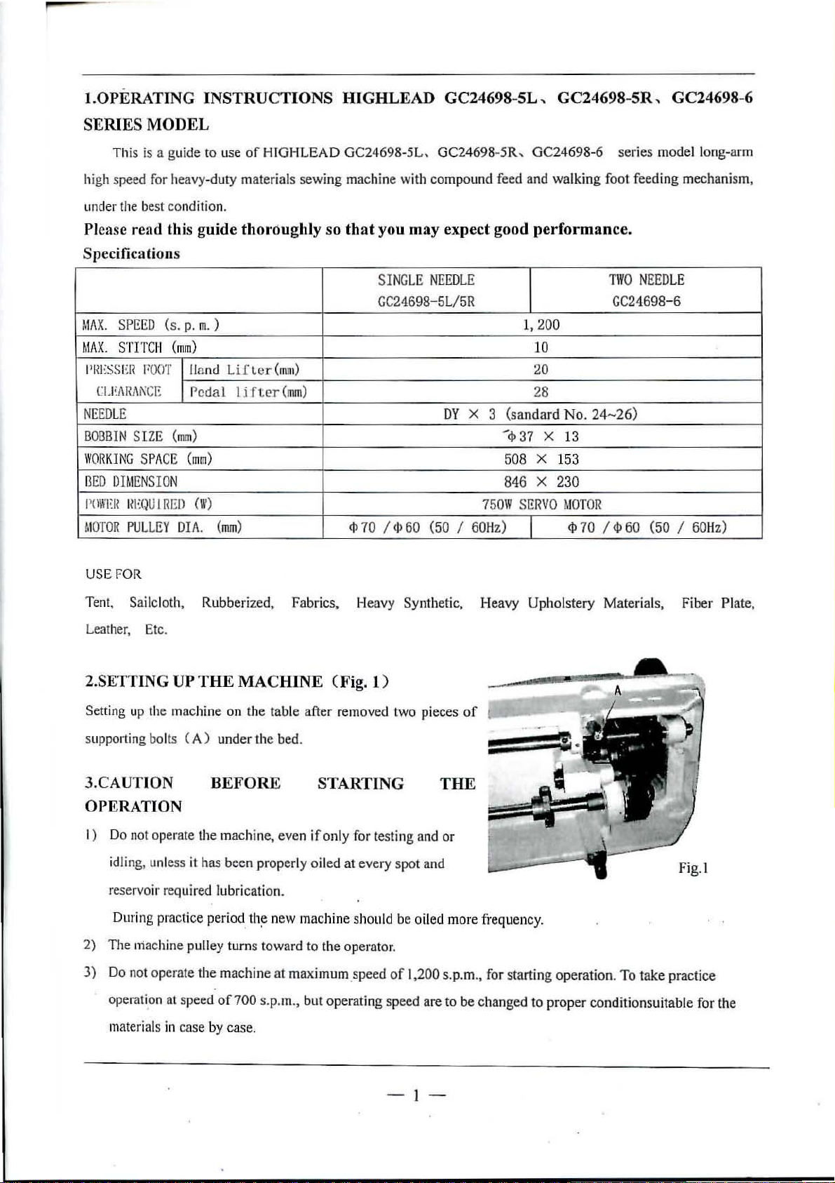
2.SETTING UP
Setting up the machine on the table after removed two pieces
supporting bolts ( A ) under the bed.
3.CAUTION
THE
MACHINE CFig.l
BEFORE
Fabr
ics, Heavy Synthetic, Heavy Upholstery Materials, Fiber Plate,
)
STARTING
THE
OPERATION
I)
Do not operate the machine, even
idling, unless it has been properly oiled
reservoir required lubrication.
During pract i
2)
The
niachine pulley turns toward to the operator.
3) Do not operate the machine at maximum.speed
ce
period.
th
~
if
only for testing and
at
every
spot
n
ew
machine should be oiled more frequ ency.
of
or
and
1,200 s.p.m., for starting
of
± -
ope
ration.
To
take practi
Fig. I
ce
operati.on at speed
materials in case by case.
of700
s.p.m., but operating speed are to
be
changed to
- 1
proper
conditionsuitable for the
Page 4
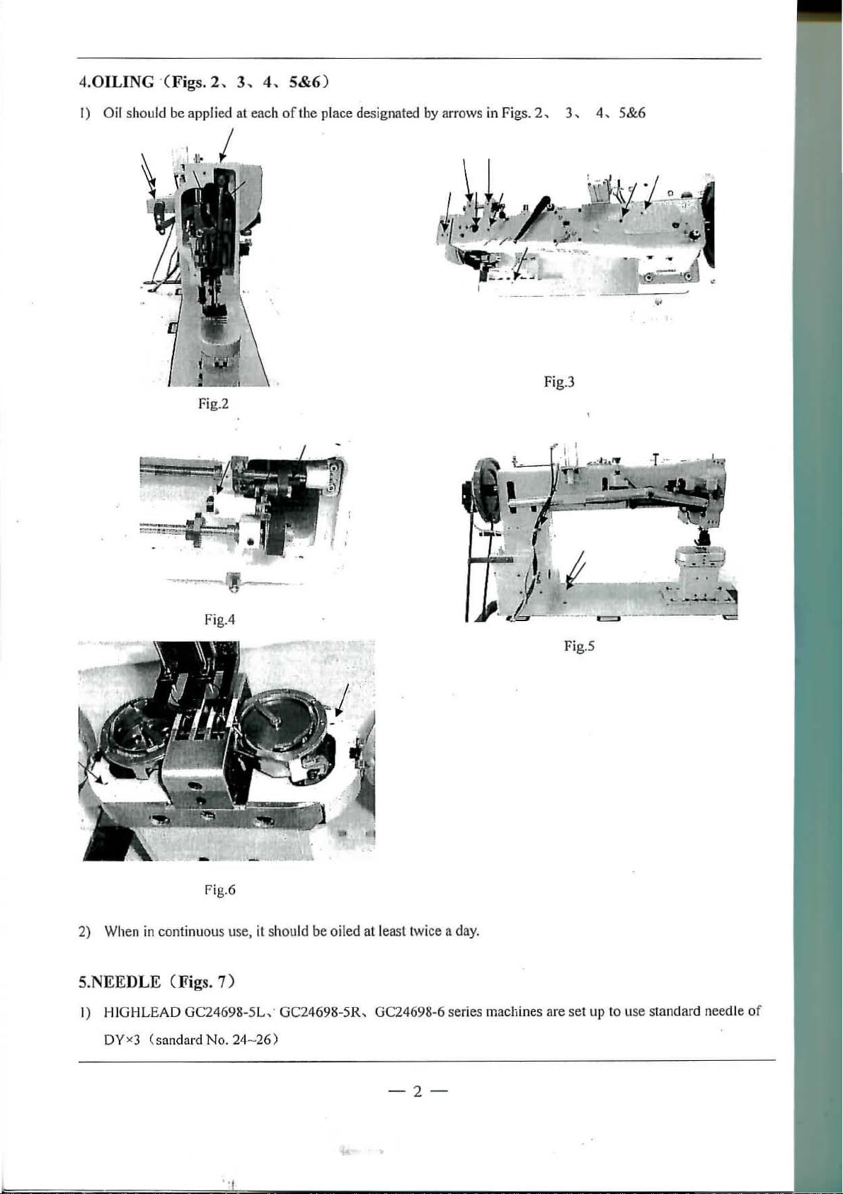
4.0ILING ·(Figs.
2,
3,
4, 5&6 )
I) Oil should be applied
Fig.2
at
each
ofthe
place designated by arrows in Figs.
2,
Fig.3
3,
4,
5&6
Fig.4
Fig.6
2) When
in
continuous use,
S.NEEDLE (Figs. 7)
it
should be oiled
at
least twice a day.
Fig.S
c=:~~
-·--
..
.
I • •
.-
~
..~
~
I)
HIGHLEAD
DYxJ
GC24698-5L,
(sandard No. 24-
· GC24698-
26)
5R,
GC24698-6
ser
ies machines are
-2-
set
up to use standard needle
of
Page 5
. . ..
.
.·#
~
"'
· '
.:
·
..
...
.-
--
~:-
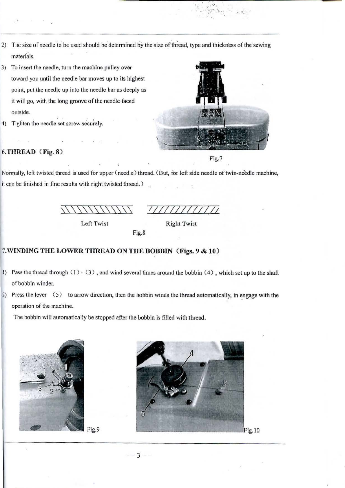
2) The size
materials.
3)
To
toward you until the needle bar moves up to its highest
point, put the needle
it
outside.
4) Tighten the needle
of
needle to be used shou
insert the needle, turn the machine pulley over
up
into the needle b3r as deeply as
will go, with the long groove
set
screw secu;·ely.
ld
be' determined
of
the needle faced
by
the size
of
thread, type and thickn·ess
6.THREAD (Fig. 8)
Fig.7
No'rmally, left twisted thread is used for upper (needle) thread. (But, for left side needle
it
can be finished
in
fine results w!th right twisted thread.) .
\\\\\\\\\\\\\
1//IIZZZIZ(I;
of
the
sewing
of twin-ne'ectlc machine,
Left
Twist
7.WINDING THE LOWER
I)
Pass the thread through ( I ) - ( 3 ) , and wind several times
of
bobbin winder.
2)
Press the lever (
operation
TI1e
of
bobbin will automaticaliy
5)
the machine.
THREAD
to arrow direction, then the bobbin winds the thread automaticall
be
stopped after the bobbin is fillecl with thread.
ON THE BOBBIN (Figs. 9 & 10)
Fig.8
Right
Twist
aro~..;nd
the bobbin (
4)
, which set
y,
in
up
to the shaft
~ngage
with the
Fig.9
-3
-
.10
Page 6
B.
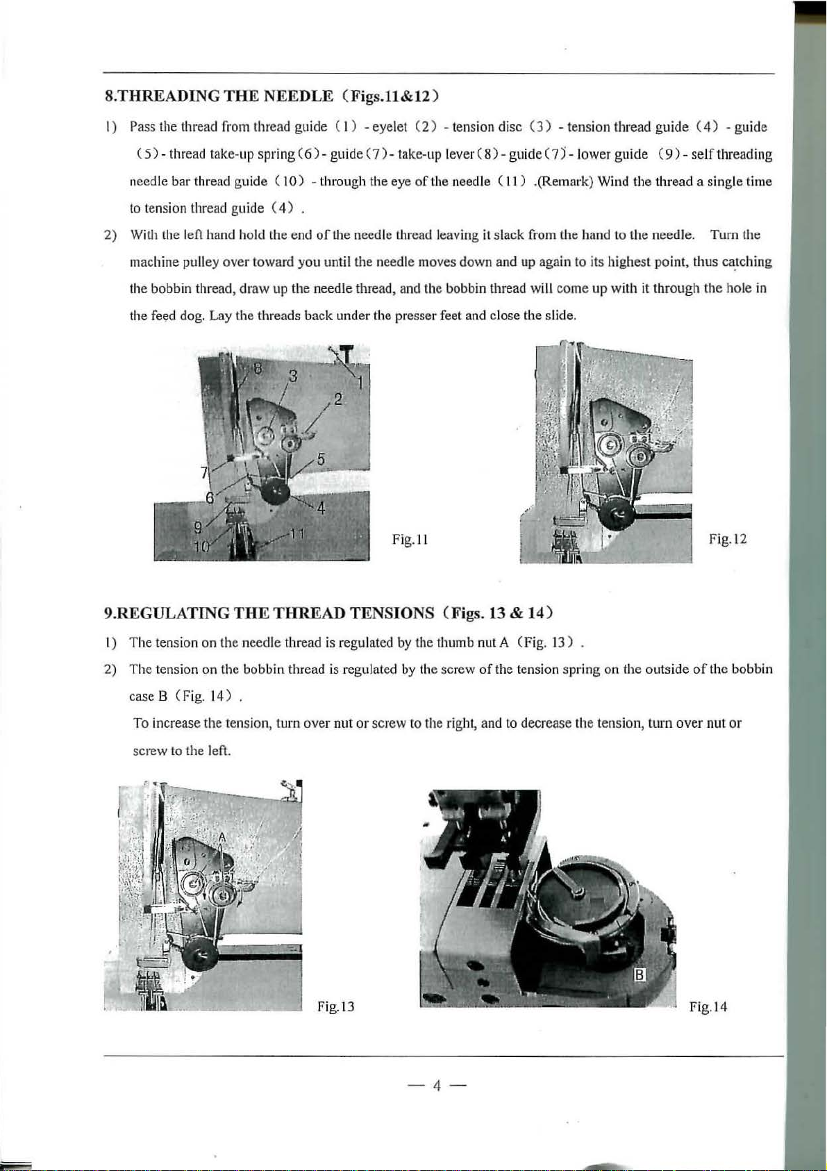
THREADING
THE
NEEDLE (Figs.11&12 )
I) Pass the thread from thread guide ( I ) - eyelet (
( 5)- thread take- up spri
need le
to tension thread guide (
2) Wi
machine
the bobbin thread,
the feed dog. Lay
bar
thread guide ( 1
th
the left hand hold
pulley
over
the
ng
(
6)-
gu
ide (
7)-
take-up lever (
0)
- thro
ug
h the
eye
4)
.
the
end
of
the needle U1read leaving it
toward you until
draw
up the needle thread, and the bobbin thread will
threads
back
the
needle moves down and up again to its high
under the presser feet and close the slide.
-
~
1
2)
- tension disc (
8)-
of the needle (
slack
3)
- tension thread
guide (
7)-
l
ower guide
11
) .(Remark) Wind
from
the
hand
come
guide
(
9)-
se
the
thr
ead a sing
to
the
needle. Turn the
est
point, U
up with it through
(
4)
- guide
lf threading
le time
ms ca.rching
the
hole in
9.REGULATING
I)
The
tension on the needle thread is
2)
The
tension on the bobbin thread is regulated by the screw
case B ( Fig. 1
To increase the tension, turn
screw to the left.
THE
4)
Fig.
ll
THREAD TENSIONS (Figs. 13 & 14 )
reg
ulated by the thumb nut A
.
over out
or
screw to the right, and
(Fig.
13)
of
the tension spring on the
to
decr
ease the tension, turn
outs
ide
over
Fig.l2
of
the bobbin
nut
or
Fig
.l3
-4-
Fi
g.l4
Page 7
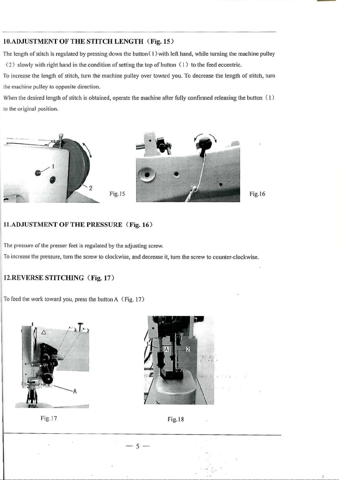
lO.ADJUSTMENT OF
Th
e length of stitch is re
(
2)
slow
ly with ri
gulated
ght
hand in the cond ition
THE
STITCH LENGTH (Fig.
by
pressing
down
the
of
setting the top
15)
button ( I ) with l
of
button ( 1 )
eft
hand,
while
to
the
turning
feed
ecce
the
machine pull
ntric.
ey
To incre
the machine pu
When the desired l
to the original position.
ase
the l
ll
~
ength of
ey to opp
ength of
1
stitc
h, turn the
osite direct
stitch
is
ion.
obta
machine
ined,
operate
pulley
over tow
the machine
•
Fig.
IS
ll.ADJUSTMENT OF THE PRESSURE (Fig.16)
ard you.
after fully con
To
decrease
firmed r
the l
ength of stitch, turn
eleasi
ng the
button
Fig
( I )
.l6
The pressure
To increase rhe pressure, tum the
12.REVERSE
To feed the work t
of
the
presser
STITCHING (
owa
rd
you,
fee
t is regulat
press t
..
...
.
~
r
ed
by
screw
to
clockwise, and
Fig.17
he
button A (Fig. 17 )
..
j
the
adjusting screw.
)
decrease
it,
turn the
screw
to coun
ter-cl
ockwise.
Fig.l7
-5
-
f.'ig
.18
~
. . . -
·.·
J
Page 8
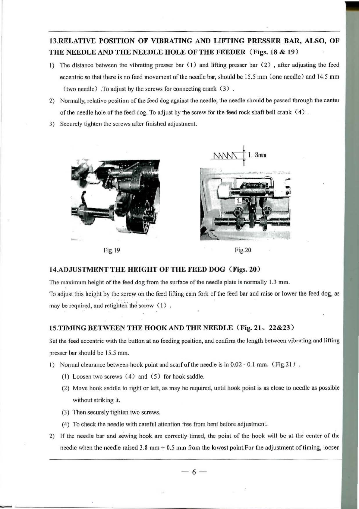
13.RELATIVE POSITION OF VIDRATING AND LIFTING PRESSER BAR, ALSO, OF
THE NEEDLE AND THE NEEDLE HOLE OF THE FEEDER (Figs. 18 & 19)
l)
The
distance between the vibrating presser
ecce
ntric
so
th at
there
is no feed movement
(two
needle ) .To adjust by
2)
Normally, relative position
of
Lh
e needle hole
3)
Securely tighten the screws after finished adjustment.
of
the feed
the
screws for connecting crank
of
the feed
dog
. To adjust by the screw for the feed rock shaft be
bar
( 1) and lifting presser
of
the n
eed
le bar, should be 15.5 mm
(3)
dog
against the needle, the needle should be passed through the center
bar
(2)
, after adjusting
(one
needle)
.
ll crank
and
(
4)
U1e
14.
feed
5 mm
~
Fig.l9
Fig.20
1
.3
14.ADJUSTMENT THE HEIGHT OF THE FEED DOG (Figs. 20)
Th
e maximum height
To adjust this height by the screw on
may be
requirc:<d
of
the feed
, and retighten· the screw ( l )
dog
• 0 • • •
from the surface
the
feed lifti
ng
cam fork
of
the
needle plate is normally 1.3 m
of
the feed
bar
and raise
IS.TIMING BETWEEN THE HOOK AND THE NEEDLE (Fig. 21
mm
m.
or lowe
-.
22&23)
r the feed dog, as
Set
the feed
presser
I)
Norma
(I)
(2) Move hook
(3) Then
(4) To check the needle with careful attention free from bent before adjustment.
eccent
ric with the button
bar
should be 15.5 mm.
l clearance between
Loosen two screws (
saddle
without
str
iking it.
sec
urely tighten
hook
4)
and
to
right
two screws.
at
no feeding position, and confirm the length
point
and
scarf
of
the needle is in 0.02 - 0.1 mm. ( Fig.21 ) .
(5)
for h
ooksaddle.
or
left, as may be required, until
. .
2)
If
the needle
needle when the n
bar
and
sewing
eedle
hook
are
cor
rectly timed, the point
raised 3.8 mm + 0.5 mm from the lowest point.For
- 6 -
hook
of
point
the
is
hook
the
between
as close
vibrat
to needle
will
be
at
adjustment
ing and lifting
as
possible
the
center
ofti
ming, loosen
of
the
Page 9
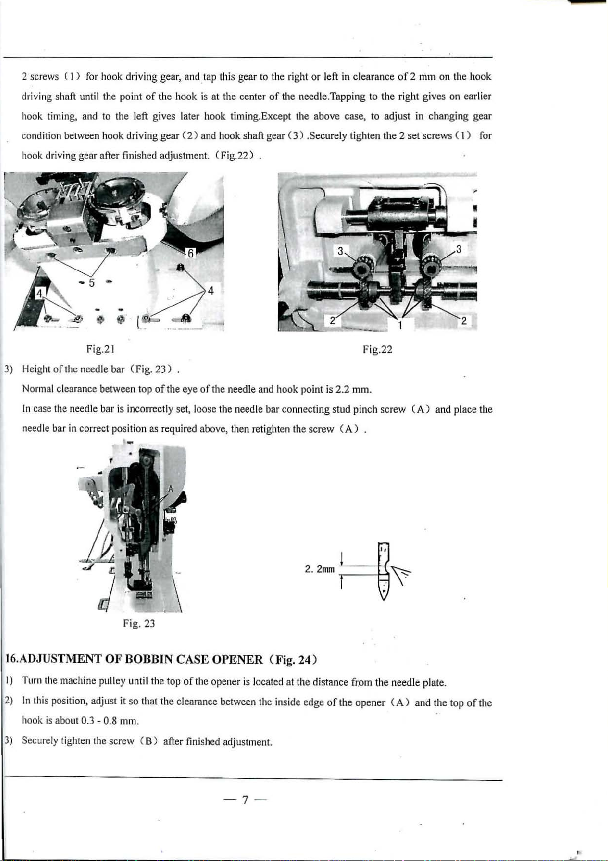
2 screws ( I ) for hook driving gear, and . tap this gear to the right
or
left in clearance
of
2 mm on the hook
driving shaft until the point
hook timing, and to the left gives later hook timing.Except the above case, to adjust in changing
condition between hook driving gear (
hook dr
3) Height
Normal clearance between top
ivin
g gear after finished adjustment. ( Fig.22)
Fig.21
of
the needle bar ( Fig.
of
the hook is at the center
2)
and hook shaft gear (
23)
of
the eye
of
the needle and hook point is
of
the needle.Tapping to the right gives on earlier
3)
.Securely tighten the 2
Fi
g.22
2.2
mm.
set
screws ( 1 ) for
gea
r
In
case the need le bar is incorrect
needle
bar
in
con·ect position
ly
set, loose the needle bar conn
as
required above, then retighten
ecti
th
e
sc
-
__
Fig. 23
16.ADJUSTMENT OF BOBBIN CASE OPENER (Fig. 24 )
I) Turn the machine pulley unt
2)
In
this position, adjust it so that the clearance between the inside edge
il
the top
\
of
the opener is located
at
the distance
ng
stud pinch scr
rew
(A)
fr.om
of
the opener
ew
(A)
and place the
.
the
neecU
e plate.
(A)
and the top
of
the
hook is abo
3) Securely tighten the screw
ut
0.3 - 0.8 mm.
(B)
after finished adjustment.
-7-
Page 10
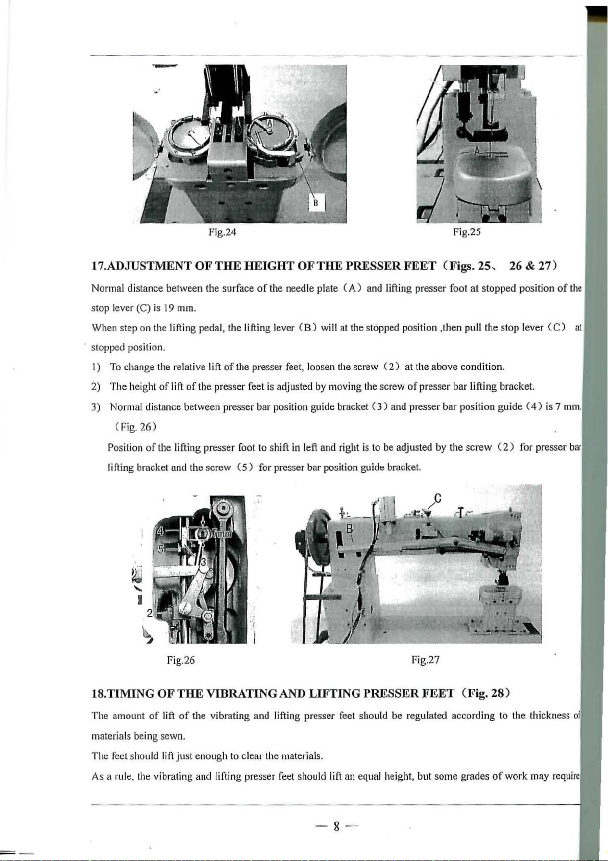
Fig.24 Fig.25
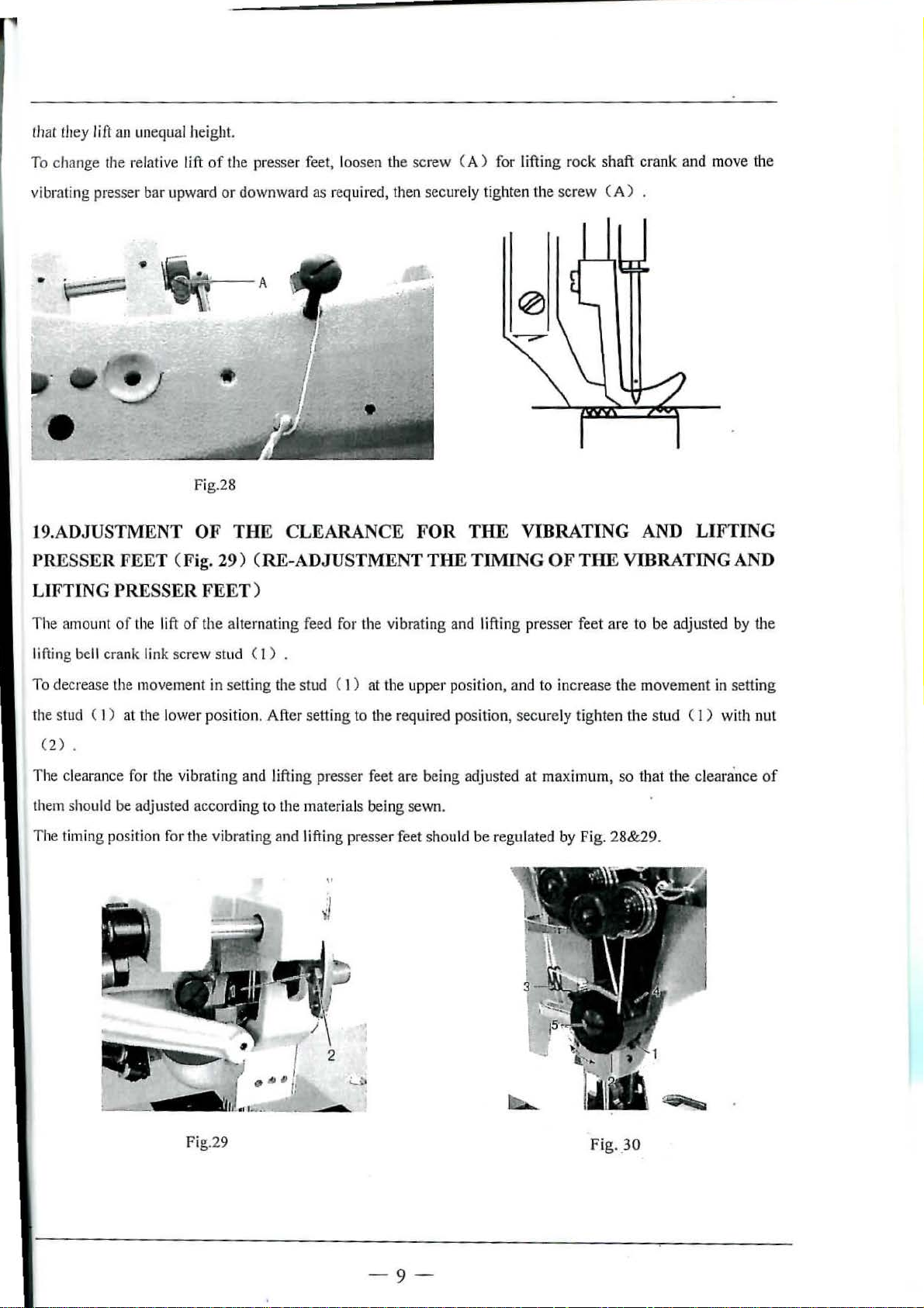
17.ADJUSTMENT OF THE HEIGHT OF THE PRESSER FEET (Figs. 25 , 26 & 27)
Normal distance between the surface
stop lever (C) is 19 mm.
When step on
stopped position.
I)
To change the relative
2)
The
the lifting pedal, the
height
of
lift
of
Lift
of
the presser feet is adj usted by moving the screw
3) Normal distance between presser bar position guide bracket
of
the needle plate ( A) and lifting presser
li
fti
ng
lever (
B)
will at the stopped position ,t
the presser feet, loosen the screw ( 2 )
C3)
and presser
foot
hen
at
the above condition.
of
presser bar lifting bracket.
bar
position
(Fig. 26)
Position of the lifting presser foot to shift in left and right is to be adjusted by the screw (
lifting bracket and the
screw
( 5 )
for
presser bar position guide bracke
t.
at stopped positio n
pull the
stop
guide
2)
lev
er
(4)
for presser
of
U
1e
(C)
at
is 7 mm.
Fig.26 Fig.
18
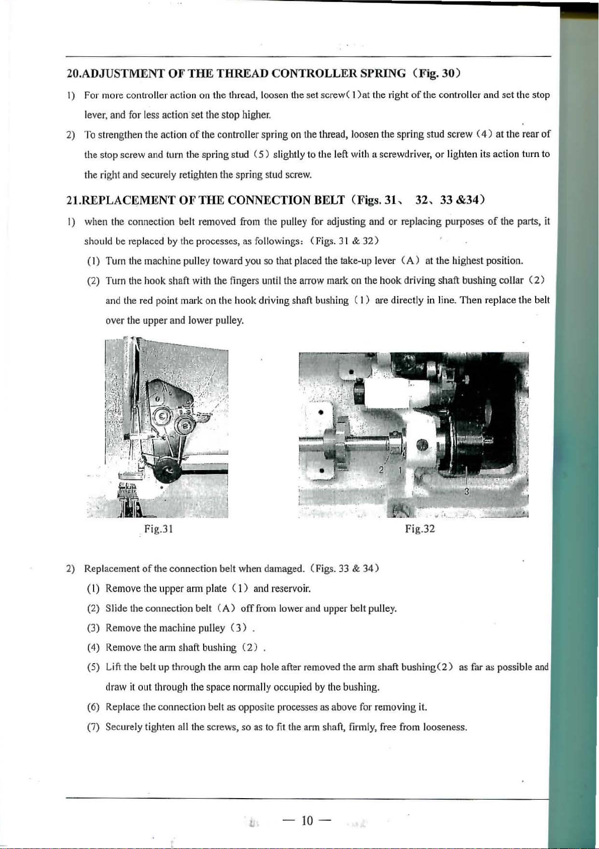
.TIMING OF THE VIBRATING AND LIFTING PRESSER FEET (Fig. 28)
The
amount
materials being
The
feet should lift
As a rule, the vibrating and lifting presser
of
lift
sew
just enou
of
the vibrating and lifting presser feet should be regul
n.
gh to clear the materials.
fe
el should lift an equa l height, but some grades
-8-
27
ated according to the thi ckness
of
work may
require
Page 11
that
they
/i
ft
an une
qual
heig
ht.
To change the relative lift
vibrating presser bar upward
of
•
Fig.28
19.ADJUSTMENT
PRE
SSE
R FEET (Fig. 29) (RE-ADJUSTMENT THE TIMING
LIFTING
PRESSER FEET)
OF
the presser feet, loosen the screw (A ) for lifting r
or
downward as required, then securely
tighten the screw
ock
shaft crank and move the
(A)
.
THE CLEARANCE FOR THE VIBRATING AND LIFTING
OF
THE VIBRATING AND
The amount
lifting be
To decrease the movement in setting the stud (
the stud (
(2)
The clearance for the vibrating and lifting presser feet are being adjusted
them should be adjusted according to the materials being sewn.
The timing position for the vibrating and lifti
of
the lift
ll
crank link screw stud ( 1) .
I ) at the l
.
of
the alternati ng feed for the vibrating and lifting presser feet are to be adjusted by the
ower
position. After setting to the required position, s
I )
at
the upp
ng
presser feet shou
er
position, and to increase the
ld
be regulated
,,
mov
ement in setti ng
ecur
ely tighten the stud ( l ) with nut
at
maximum,
by
Fig. 2
so
that
8&29
the clearan
.
ce
of
Fig
.29
-
9-
Fig._30
Page 12
20.ADJUSTMENT OF THE THREAD CONTROLLER SPRING (Fig. 30)
I) For more controller
lever, and for less
2) To strengthen the action
the stop screw and turn the
the right
and
action on
action·
secu
rely retighten
the
thread, loosen the set screw( 1
set
the
stop
of
the contro ller
spring
the
higher.
stud
spring
spr
ing
(5)
slightly
stud screw.
)at
the right
on the thread, loosen
to
the left with a screwdriver, or light
the
21.REPLACEMENT OF THE CONNECTION BELT (Figs. 31,
I)
when
the
connection belt removed from the pulley for adjusting and
should be replaced by
the
processes,
(1) Turn the machine pulley toward
(2) Turn the hook
and the red
over
the upper and lower pulley.
shaft
point
with the fingers until the arrow mark on the
mark
on the hook driving shaft bushing ( I )
as
followings: (Figs. 31 &
you
so
that plac
ed
the take-up l
or replacing
32)
ever (A)
book
are
directly in line.
of
spring
32,
drivi ng
the
controller
stud
33 &34)
purposes
at
the high
shaft
screw
bushing
Then
and
set
the stop
(
4)
at
the
en
its action turn to
of
the parts,
est
position.
collar
repl
ace
the belt
rear
(2)
of
it
Fig.31
2)
Replacement
( I) Remove
(2) Slide
(3) Remove the machine pulley (
(4) Remove the
(5)
Lift
draw it out through the space n
(6) Replace
(7)
Secmely
ofthe
connection belt when damaged. (Figs. 33 &
the
upper arm plate ( 1 ) and reservoir.
the
connection belt
ann
shaft bushing
the be
lt
up through the
the
connection belt
tighten all the screws,
(A)
offfrom
3)
(2)
ann
cap
ormally occupied by the bushing.
as
opposite processes
so
low
er
and upper belt pulley.
.
hole after removed the arm shaft bushin
as
above for r
as to
fit
the arm shaft, firmly, free fi·om looseness.
-10-
34)
emoving
Fig.32
it.
g(2)
as
far
as
possible
and
Page 13
1
2 3
'•
'
•
Fig.33 Fig.34
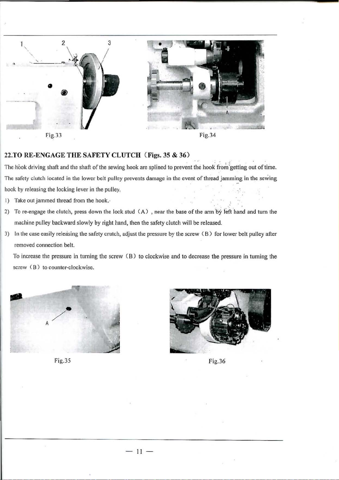
22.TO RE-ENGAGE THE SAFETY CLUTCH (Figs. 35 &
The
hook driving shaft and the shaft
The
safety clutch located in the low
hook
by
releasing the locking lever in the pulley,
Take out jammed thread from the hook.·
I)
2) To re-engage
machine pulley backward slowly by right hand, then the safe
3)
In
the case easily releasing the safety crutch, adjust
removed conn
To increase the pressure in turning the screw ( B) to clockwi
sciew
(B)
th
e clutch, press down the l
ect
ion belt.
to counter-clockwise.
of
the sewing hook are splined
er
belt pulley prevents damage in the
ock stud (A) , n
the pressure by the screw ( B ) for l
ear
ty
se
to
the ba
clutch wi
and to decrease
36)
prevent the bo
eve
nt
of
thread
se
of
the
arm
ll
be released.
oR
t'rorh :igetting
jamming
. . '
:
1:>~
l
eft
ower
the
pres
out
of
time.
in the sewing
band and turn the
belt pulley after
sure
in turning
the
rig.3s
-11-
Fig
.36
Page 14

A.
ARM
BED
AND
ITS
ACCESSORIES
39-
2
33
I
10
~
15
15
er1s~
~16
I)
38~
37'
-12
-
Page 15

A.ARM
Fig. Part s.
BED
Nos Nos
AOI
IIE924B710l Foo
lli\10062110
A02
A03
IIE913B800
117214HBOOL
A04
i\05
HE9L5B
B001
1\0
6 .
HE916B8001
1\07 11Al00C2170
1\0B
IIE
9L7B8001
1\09
HF
410B8001
1\10
IIE919D80
1\11
IIE
1\13
II
F4lll3800 1 Foot
i\14
IIE04808001
~IE020B800
A15
i\
16
IIE021B8001
Al7
1132
AlB
HE969B7101
i\19
116756138001
i\20
HA500C2070
i\21
HE045D8001 Washer
i\22
I
IE927B800 I Screw
i\23
HE928B8001
A21
HEI
i\25
IIE9
i\26
HE9
i\27
HE
i\28
~IE93208001
i\29
IIE933B
i\30
IIE9
i\31
11
73270800
i\32
IIE93708001
1\33
HE938B800I
i\34
IIE939B8001
i\35
IIE025C8001
A36
HG01B37101
A37
HD808B7101
i\38
11415050140
A39
H0313L8001
J\10
IIF41508001
i\41
1
1415060
J\42
IIEOlOMBOOI
A43
HF41
M4
J
12oomwo9o
M5
II
E956ll8001
01
9200800 I Foot
12li304
L1F8001
29138001
30B800
93Hl800
800
34ll800 L Arm
150
6B800l
AND
IT'S
t lift
er
Screw
I Collar(upper)
Screw
Foot
lifter
Colladlower)
Screw
Foot 1 i
Foot
fte1·
1 i
fter lift
Pin
lHter
lifter
Screw
L
Thread
guide
Nut
Washer
Thread
tension
Thread cutter
Screw
Lubricating oil
Set
screw
Oil
pad
L Oil wick
1
Vinly
tube
Oil
wick
L
Vinly
tube
oil
cap
I
Arm
oil
plug
Face
plate
Face
plate
Thread
guideOower)
Screw
Touch
switch assy.
1
ens1on1ng
Screw
Cylinder
Cylinder bracket
Screw
Screw
Cylinder
Ball
joint
oil
Supporting bolt
ACCESSORIES
Descrip
lifting
lifting
lifting
lifting
lifting
thumb
wnee
tion
lever latch
lever
lever latch shaft
ing lever
lever hinge stud
lever spring
mechanism
cap
screw
1 assy.
latc
hand
h spring
....l 0:::
<.0
1.(}
I
co
en
<.0
c-1
""'
u
c.:>
le 1
I I
co co
en
<.0
('.)
""'
u u
c.:> c.:>
1
3 3 3
1 1
1
1 1 l
1 1 1
1 1 1
1 1 1 S
1 l 1
1 1 1
1
l
1 1 1
1 1
1 1 1
1
1
1 1
1 1
1 1 1
I
1
2
2
1 1
1
1 1 1 SM3/16
1 1 1
1 L
1 1
1 1
1 1
1 1
l 1 l
1
1 l
1 1 1
l 1 1
1 L 1
1 1 1
2
2 2
1 1 1
l l 1
2 2 2
1
1 1
1 L 1
4 4
2
2 2 S
1 1
5
5 5
3
3 3
1.(}
en
<.0
N
""'
1
SMll/64
(40) X 6.
SM11/64(40) X4.
Ml/8(44)
X4. 5
1
1
SM17
/64(24) X 8
2
SM?/32(32)
2
1
1
2 SM9/64 (40) X 8
(28) X 6.
SMl/8
(44)
1
1
1
1
X 7
1
SM13/64
SMl/8
SDA32X50
4
1
ML7/
(32)
(40) X 3.
-B
64(24)
No
X 7
X8
tes
5
5
5
3
-1
3-
.
..
Page 16

B.ARM
SHAFT
MECHANISM
1
- 14 -
Page 17

B.
ARM
SHAFT
MECHANISM
Fig.
Nos
001
002
130:3
llOiJ
1305
1306
B07 IIE
008
009
010 IIE910C800
811
013
014 1131
13
1316
017
IllS I lE
13
020
13
1322
1323
1324
025
13
13
1328
B29
Parts. a>
Nos
HP40
4C8001 1\
HE
905C8001 Thread
II
E906
C800 1 Th
HE907C800
IIE020C800
I lA L00
1321
l Oil
I Set
50
908C800 1 Th
f
ii!
035C8001
HE909C
8001
1 Needle
IIA100C2070
IIA100C2060
OOC207
0
15
IIE041C8001
llfl0139J001
IIE9IIC800
19
IIE912C8001
O
1 Set
11
CSCO I Washer
IIE010G8001
21
I~
EO
14C800
1 Oil
IIE020C800l
HE914C8001
HE023C800l
HE916C8001
26
HE014C8001
27
H
E020C8C01
I
!E939G8001
H6623C8001
1331 HE026C8001
1332
ll3205C0G61
13
33 HE006
634
8:.15
B36
037
1338
1339 flfll
BiJO
041
1342 IIE007C8\l0
1343
0114 114l07
1345
D8001
I
~Eo:l0C8001
IIE
028C80
0l
HE9L7C800
1
113205]0662
UF405C8001
OOC2
020
IIF'407C8001 Machine pulley
HE038E8001
I
HE92IC800l
00672
IJE922C8001
tO
13
I
l
co
0)
tO
'<t' '<t'
c:-:1
(.)
c.=> c.=>
I 1 l
rm sh
aft
Descrip
tio
n
co
tO
'<t'
c:-:1
g
take-up lever I 1 l
read take-up lever hinge stud 1 1 I
wick
screw
Rub
ber plug
read take-up
slide
block 1 l 1
Oil wick
Needle
Pos
Set
Needle bar c
Oil
ition
screw
wick
l.lar
connecting
l.lar
crank 1 1 1
lin
k 1
screw
onn
ecting li
nk
stud 1 1
Set screw L
screw
I
1 1
2 2
2
2 2 2
l 1
1 1
L
1 1
1 1
1 1 1
1 1 S
1
1 1
l 1 1
1\rm
shaft
bushing
Oil
wicl<
pad
Set
screw
P
eed dri
Set
ving eccen
screw
Arrn shaft cente1·
Oil
pad
Set screw
Pulley
Screw
Oelt pulley(
Spring flange
Sot
screw
Checl< screw
Position
screw
Connection belt
Bearing
Ann
sh
aft bu.shing (right)
Screw
Set screw
Machine pull
l
~ok
dr iving shaft l
Spring
Shaft l
JUs
hing
uppe
ey
(left)
tric
busf.ing
r)
adjusti
ock stud.
ng
scr
ew
l l 1
I 1 1
1 1
]
1
1
1
2 2
I
1
1 1
l
1 1
! 1
2 2 2
L 1 1
2 2
1 l 1
1
1 l
l
1
1
l 1
I 1
]
1
2 2
1
1 1
2 2
1
1 1
1 1 1
! 1
1
l 1
g::
ln
l
co
0">
tO
N
(.)
1
1
1
M1
3~117/64
1
SM17/64(24)
1
1
2
1
1
1
M1X8
2
L
1
1
SMt5/6
2
2
l
Note
7/64 (24) X 6.
(2
4} X 3.
X20
4(28}
s
5
5
-1
5 -
.
..
Page 18

B.
ARM
SH
AFT MEC
Pig.
Parts.
Nos Nos
646
li6010l6100
HE9
1347
ll48
049
650
851
852
[!53
54
6
B55
B56
[!57
B58
B59
B60
23C8001
11E035G8001
IIE034G8001
HE9
24C800
11320
5C066
HF408
C80
HE022G8001 Screw
l
iE925C8001 Long
HE926C8001
HE927C8001
HE0281!8001
H
E028G8001
IIE029G800l
1!6010
1205
B61 HE027G8001
1362
H
E026G800l
11
B63
E031C8001
HAN1SM
Descrip
stud
Hook
driving
shaft
Set screw
Pos
iti
on
screw
Be
1
l t pulley(
lowe
L pring flange
01
Lower
shaft
lever
for
Set
scre
w
Pin
Set screw 2
Shor
t lever for pulley
0 pin
tio
n
loci<
ratchet. 1
r) 1 1
pulley 1 1
....:I
(0
Ln
I
00
O'l
(0
..qt
C':l
u
t.:>
I I
00 00
O'l
(0
'Q' 'Q'
C':l
u u
t.:> t.:>
1 1
1
1 1
1 1 1
.2
2
l 1
1 1 1
2
1 l
e:5
O'l
(0
C':l
1
1
2
1
2
1
SM5/32
Notes
(40) X 3.
6
-
16
-
Page 19

C.PRESSER
4
I
lj
FOOT
MECHANISM
32
28 \ .
'0
~
-33
51
10
~
64
57_n
~
55"-~b
@~
53
67
\
68
. I 54
c.
56-
-17
'f;9
f&;
-
Page 20

C.
PRE
SSER
Fig,. Parts.
N
os
No
s
FOOT
MECHANISM
Description
<0
I
00
en
<0
'<!'
C'-.1
u
<:.:>
.....) p::
In
'f
I
00 00
en en
<0
<0
'<!' '<!'
~
(.!)
~
No
tes
COl
HE90408001
C02
HE905
08001
C03
HE035C8001
CG4
llE009G8001
111::90708001
C05
C06
IIE041C8001
C07 JiE119E8001
II
09
IO
ll
E90808001
HE9
0908001
Hl!910D80P
IIE9ll08001
l
cos
C
C
C
Cl2 HE022K800l
Cl3
HE912D8001
HE0060800l
C14
HE0070
HE0
8001
0608001
C15
Cl6
C17 HE913D8001
CIS
HE00
908001
Cl9
C20
HE914D800
H3107G0661
1
C21 HE91508001
C22
C23
HE916D800
HE00706001
1 Set screw 1
C24 HE91808001
C25 HE919D8001
ILE
C26
C27
C28
C29
C30
C31
C32
C33
C34
C35
C36
C37
C38
C39
C40
C41
C42
C43
920D8001
HE92108001 reed lifti
HE024D8001
HE02508001
IIE035C8001
H3112F0662
HE922D8001
IIE0
38E8001
HE
92308001
HE9211D8001
11
3l07G0662
HE92508001
11E92608001
HE927D8001
HE035C8001
IIE92808001
H
E92908001
H
l'4040710
1 N
Needle
Needle
Oil
bar guide bracket
bar guide bracket stud
wick
1 1
1
Set screw 1
Need
le b
ar
connection stud 1 1
Oi 1 wick
Set screw
Needle
bar(3/4
N)
1
2 2 2
1
Needle 2 1
Needle
set
screw
2
Position bracket l
Screw 1
Presser bar position guide
Set screw
Presser bar bushing
(uppc1·}
l
1 1
1 1
Set screw 2 2
Presser bar pos
Set scr
Presser
ew
bar l
itio
ifting
n guide lev
er
bracket 1
Set screw 1
P1·esser bar spring bracket 1 1
Presser bar bushing(lower)
Presser bar 1
Lifti
ng presser foot(3/4H)
Set
scr
ew
ng
rock
shaft
Lifting
Screw
Oil
Nut
stud
wick
roclt
shaft
bushing 2 2 2
1 1
1 1
1
Lifting eccentric
Position sc
rew
Lifting eccentric connection
Lifti
ng
bell
crank 1
Set
scr
ew
Lifting
Link
Vibrating
Oil
Vibrating pres
Set
eed
bell
crank link
pr!l"sser
wick
ser
sc1·ew
le
bar vibratin cra
1
bar 1
1 1
foot(3/4H) l
1 1
nk shaft
1
1 1
1
1
1
1
1
1
.l
SM5/32 (40)
OY
X3
SM3/l6(32)
SMll/64(32) X9
1
1
2
1
1
1
1
SMO.
1339(36) X 16.
1
1
1
1
1
SM1l/64
1
1
1
1
11/64(40) X7. 5
1
#25
(40)
(32)
(40)
X 9
X5.
5
X6. 5
X 13.5
7
-18
Page 21

C.PRESSER
Fig.
Parts.
FOOT
Nos Nos
MECHANISM
Descriptio
n
~
co
m
<0
..,.
N
u
<.:1
.....l
In In
I
co
co
m
N N
u u
*
<.:1
0::
I
m
<0
..,.
<.:1
Notes
113100r2270
C44
HE027E8001
C15
C46
HE0
28E800
1 Set
C4
7 IIE933
C18
D8001
IIE038E800
1
C49
cso
HE035C8001
C5l
HE
935D8001
C52 HE93608001
IIE937D8001
C53
C54
111!93808001
IIE926E8001
C55
IIE0
38E800
C56
C57
~
W20
C58
HF'304D8001
C59
H£93908001 Vinyl
I
IF20908001
C60
C61
HE044
C62
IIE940D8001
C63
IIE94108001
1 Stop
7D8001
J8001 Washe
C64 HD611B8001
J-1007009100
C65
C66 II
C67
C68 IIY
D71
114310
1101800
2F800
400
l
40
1
C69 HY10D9800l
C70
C71
11431060
HY
1W0800 l Connecti
Needle
Screw
bar ro
ck frame
slide block
stud 1 1 1
screw
Needle bar vibrating crank(right) 1
Set screw
Co
nnection
Oil
wick
lin
k
Hinge screw
Nu
t
Peed conn
Feed conn
ecting
ecti
ng
screw stud
crank
(left)
Nut
screw
Vibrati
Lif
ng
presser foot
tin
g presser foot
tube
Vibrati
ng
presser bar(single needle)
r
Nut
Dushing
Bushing
St
op ring
Collar
Screw
Shaft
Cran
l<
Screw
ng
rod
1
1
1
l l 1
1 1
1 1 1
1 l 1
1 l 1
1 1
I 1
1
3 1 1
3 1 1
1 1
l 1
1
1
l 1
1 1 1
1 1
1 1
1 1 1
1 1 1
2
2 2
1 1 1
1
1 1
2 2
1
1
1
1 1 1
1
1
1
1 1
1
1 S
1 S
1
1
1
1
M17
MO.
S~
IO.
/64(24)
309
(20)
1339
(36) X 16.
7
-1
9-
Page 22

D.STITCH
REGULATOR
AND
FEED
ROCKING
MECHANISM
27
I
~
fiJ
I
26
-22
13
55
-
1~®
ll
' .
56
5
'i
I
j
18
r--19
-17
-
20-
Page 23

D.STITCH REGULATOR
Fi
g.
Parts.
No
Nos
s
AND
FEE
D RO
Description
CKING
MECHANIS
lO
I
00
0'>
<.0
'<11
C'l
u
~
M
-l
1.0
I I
00 00
0'> 0'>
lO lO
'<11 '<11
N
u
~ ~
13
~
N
otes
DOl
I
IE9
46E80
IJ
02 HE905E80
003
IIE906E8001
00
•1
HE907E800
005 IIE908E8001
II
006
00
D
009
010 H
Dll
01
013
014
E909E800
I
lA I
7
OS
OOB2l10
HE910
~IE911E800
E912E8
I
IE03
5G800
2
HE023C8001 Set scr
IIE913E8001
IIE914E800!
015 BE915
016
11601015100
017
HY10E68001
01
8
D19
0
20
7G0661
H3l0
HE035C800!
reed driving eccentric 1 1 1
01
Flan
01
S
et
1 Set
fo'ri
St
l
Set s
Pee
E80
01
Spring
1
00!
Coll
I Position sc
Feed
Spring
E8001
Bushing
Snap
Feed
Pin
Oil
021
22 11Y10E8800! l'ee
0
023
IIE920E80Dl
0211
112013]0065 Washer
025
IIE02211800!
026
IIE
02011800
027 IIE025B8
001
Feed
Screw
1 Oil
Screw
028 BE92IE8001 re
029
IIE922
E80
01
Set
O
:lO
IIE9
23E80
01
l'eecl
031 IIE131E8001 Nut
0
32 I IF104E8001
033
111!
033118
034
IIE034H800
0
35 IIE033
036
D37
0
38
039
040
04
1 I
042
043 IIE9
1 18
HE03411800i
IIE943E710
IIE928E800 1
IIE929E800
IIEOl2
E800
JE930E8001
IIE035C800!
26E800
Feed
00
1
reed d
1
Set
001
Feed
S
1
Feed
reed
l Collar
J Set
Binge
O
1
Nut
et
il
ge
screw
scr
ew
cti
on
plate
op
screw
crew
d driving eccentric adjusting
ar
rew
ew
reg
ulating
stud
disc
1 1 1
1 1 1
1 1 1
1 1 1
2 2
2 2
1 L
1
1 1 1
1 L L
1 1 1
2 2 2
1 1
1
1 1 1
1 1 1
pin
driv ing
connect
ion
l 1
1
1 1 1
ch screw 1 1 l
wick
d bar
bar forked
pad
ed
bar cra
nk
screw
bar hinge screw
driving rock sha
riving
scr
rock shaft stop coll
ew
driving rock
scr
ew
reversi
reversi
scr
ew
scr
ng lever
ng
ew
wick
connect
shaft
lever
ft
bu
ion
stop
shing
ar(lef
collar(r
igh
t)
t)
1 1 1
l L
1
1 1 1
1 1 1
1 1 1
1 1 1
1 1
1 1 1
2 2 2 S
1 1 1
1 1 1
1
1
1
1
2 2 2
1 1 l
2 2 2
1 1 1
1 1 1
l 1 1
1
I 1
1 1
l 1 1
1 1
SM3/ 16
(32)
SM3/16(32) X 10. 5
2 S
M3/16(40) X 11.
2
l
M17/64"(
1
1
I
1
X 10. 5
21)
X7. 7
5
-21-
Page 24

n·.
Fig
Nos
STI
TCH REGULATOR
.
Parts.
Nos
AND
Descr
F
EED
iptio
ROCKI
n
NG
ME
CHANISM
-l
tO
Ln
I
00
en
tO
~
t'\1
u
~
I
00 00
en en
tO
~
t'\1
u u
~ ~
fP
t'\1
*
Notes
044
BE931E8001
045
IIE932E8001
II
E933
046
047
048
1)49
050
051
052
053
054
055
056
057
058
059
E800l
IIY12E68001
HE935E8001
HE936E8001
BE937E800
~IE035C8001
HE926E8001
liE938E8001
111!
939E8001
I-IY12E88001 Feed
UE940E800
BE941E8
HE942E8001 Washer 2 2
H005010080
Stop
screw
Feed
Set
Feed
Spring and
Hi
nge
1 llin
ge
Oil
reversi ng lever
scre
'N
reversing link
treadle
screw nut
screw
wicl~
sli
de
block 1
connecting link 1 1
Nut
fo'
ecd 1·eversing crank
Set screw 2 2 2
reversing lever s
1 t screw
001
Nut
Spring washer 1 1
(rig
ht) 1
lide
block sprin
2 2 2
1
1
1 1
1 1 1
1
1
SM3/16(32)
1
1
1
1
1
2
X4
(24) X 17.
(
24)
5
-22-
Page 25

E.
HOOK SADDL
E
MECHANISM
0
0
a~
46
~
4
7/
)8
~
_.!-/
49
__
___
_.cs:-
-
__
----n
23-
45
Page 26
E
.HOOK
SAD
DLE
MECHANISM
Fig.
Parts.
Nos Nos
1!01 IIY10fo68001 Hook
E02
IIY11F9800
E03 IIE053C8001
1!04 I·IY11F28001
E05
HE018J8001
HY11F08001 Bob
1!06
E07
HE017J8001
E08
~
IE01
8J800
HE019J8001 Nut
E09
IIE912F8001
ElO
Ell HE
1!12
E13
El4
El5
El6
El7
El8
El9
E20
E21
911F
IIY11Fl8001
H005004050 Washer 2
IIE909P8001
111!52
4]800
HE517J8001
IIE517J800l
111!521]8001
HE522J8001
II
E520]8001
HY12Pl80
E22
U9
017H8001
H7206E800
E23
IIY1
0F77101
HY10F88001
H415050160
H005008050
E24
IIY10F9800t
E25
HYl2E3800l
1!26
HE533]8001
1!2
7
HE532J8001
E28
HE517]800l
E29
IIIH23I8001
E30
IIE535J8001
1!31
IIE536J8001
E32
IIE04508001
E33
IIE021D
E3
4
HY12El8001
1!35
~IV
11
1!0
E36
HE0121!8001
1!37
ILE539J800l
E38
Bushing 2
1
Scr
Bobbin
Oil
Locating stud
Oil
1
Bobbin
8001
Hook
Bobbin
Screw
Spri
1
Screw
Screw
Hinge
Pin
Hinge
H
ook
01
Co
Screw
1
Clutch nssy. 2
Clutch
Screw
Spring washers
Con
Feed
Square block 1
Sci·
lfns
Nut
B001
reed bar
Feed dog
800
l
Screw
Screw
Nut
Descr
ipt
shaft
supporter
ew
case opener lever hinge sha
pad
bin case opener l ever
pad
case opener lever link
case opener
ng
cover
llar
ass
y.
l
lar
necting sh
pla
aft
te
set bracket
ew
her
(3/4)
~
ion
ft
<0
I
00
m
<0
oq<
N
(.)
<..:l
2
S
lf7
2
2
2
2
2
2
2
2
2
2
2
2
2
4
2
2
2
2
4
4
SM15/64X28
8
2
4
4
2
1
2
2
4
1
1
/32X32
L=6
Not
es
-24-
__
Page 27
E.
HOOK
fig.
Nos
SADDLE
Parts.
Nos
MECHANISM
Description
tD
l
00
m
tD
q<
('.1
u
c:.:>
Notes
E39
HYllr78001
E1
0
HY
11F48001
E4l
IIYll
f-5800
E<12
Hi\7121N304
E
43
~IE513J8001
Et\4
H415060300
E45
HY12F2
8001
E16
HE055G8001
BE
920
fo80
IIE921F8001
E47
IIIlO
10]800 1
HE017G8001
~IE012]800l
E48
H
E013
}80
E49
IIY
ll
F3800
ESO
HE0
58G8001
IIE017G8001
ESI
HE928F7l0l
HE
914
1'800
114707H8001
E52
IIE
020C800
E53
HI'405F7101
114726H8001
Hfo40
6F800
E54
IIA307C066
E55
114727118001
E56
fiA7311
C306
E57
HE517J800
Throat plate(3/4N) 1
Bracket (3/4) 2
Plate (3/4) 2
l
Screw
Scr
ew
Screw
Cover
plate 2
Big
gear assy.
Gear
Screw
01
Screw
Small
gear assy. 2
Gear
Screw
Scr
ew
Washer
01
Hook
Feed
Feed
driving
lifting
lifting
1
shaft
cam
cam
assy.
Screw
ll
ook
!l
1
Oi 1
Screw
1
Shaf t asse
uear i
!look
1
Screw
2
driving sh
ook driv
wick
ng
dri
6203Z
ving
aft
ing shaft
111b
ly
NTN
shaft
bushing assy.
bushing 3/4N
bushing
Holder
Screw
Screw
l
2
6
12
2
2
2
2
2
2
2
2
1
1
1
1
2
2
2
2
1
1
1
2 S
1
3
10
cb
40
M1/4
X
cb
(40
17
X 12
) X 6
-
25-
Page 28

E.HOOK SADDLE
Fig.
No
E39
E40
E4
E42
E43
Et14
Et15
E46
E47
E48
E49
ESO
ESI
E52
E53
E54
E55
E56
ES7
Parts.
s
JI
Y I L
Nos
F7800
!lVI LF480
1
HYllF58001
IIA7121N304
HM43J8001
11415060300
I-IY1
2F280
I
IE055G80
I
IE920F800
IIE9211'800
IIEO
10]800
IIE017G8001
IIE012J8001
IIE013]8001
IWIL
F3800
II
E058G800
~
lEO
17G800
IIE928F710
IIE9L4F8001
li
4707118001
IIE020C800l
HF40
5F710
11<172611800
II
F406F800
IIA307C0662
H4727H800l
HA7311
I!E5 L 7]800
I
01
01
0 1
1
1
1
1
I
1
I
1
1
1
C306
1
MECHANI
Thro
at
Bracket(3/4)
Plate (3/4) 2
Screw
Screw
Screw
Cover
Big gear assy. 2
Gear
Screw
Screw
Small
Gear 2
Screw 2
Screw
Washer
Hook dri
reed
Feed
Screw
Hook
Hook
Oil
wick
Screw
Shaft
be
aring 620
Ho
ok
Screw
Ho
lder
Screw
Screw
SM
D
escriptio
plate(3/4H) I
plate 2
gear assy.
ving sh
lifting
lifting
dTi
ving
driving
aft
cam assy.
cam
shaft
bushing assy.
shaft
bushing
assembly
3Z
NTN
driving shaft bushing
n
3/4.
'f
co
en
lO
"""
E3
(.!)
2
2
6
12
2
2
2
2
2
2
1
1
L
L
2
2
2
2
1
d
>40Xc~17
L
1
2 SMl/4
L
3
10
(40)
X12
X6
N
otes
-
25-
Page 29
F.
HOOK
.
DLE
SAD
MECHAN
· . . - .-
ISM
0
0
/
GC~4698-5L
...
45
.
-26-
53
Page 30
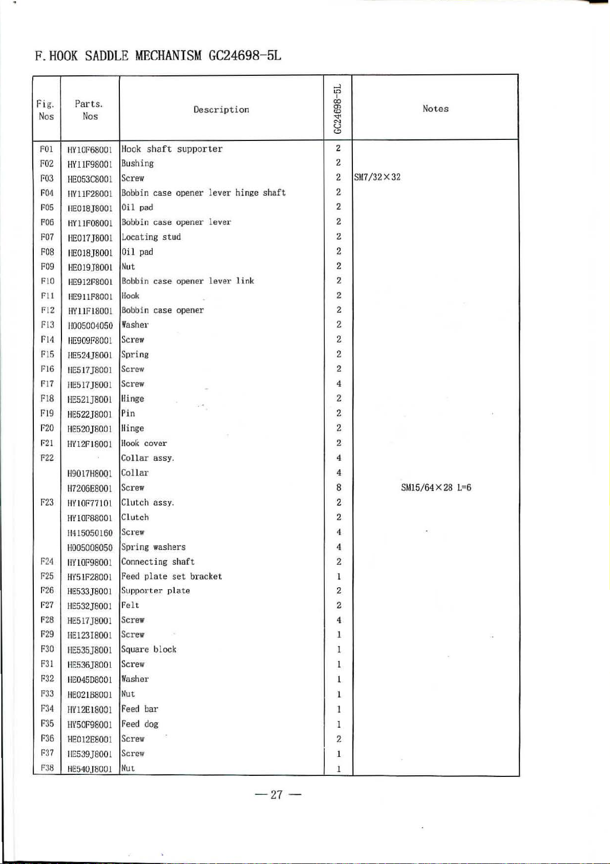
F.
Fig.
Nos
HO
OK S
ADDLE MECHANI
Parts
.
Nos
SM
Des
GC2
4698-5L
cri
ption
...-1
tn
I
00
en
<.0
~
""
u
t,!)
Notes
F01
F02
t:'03
FO<I
t:'05
F06
t:'07
FOB
[:'09
FlO
Fll
F12
F13
f.'
I
ii
f-'15
f-'
16
f-'17
F18
f-'
19
F20
F21
F22
P23
P211
P25
P26
P
27
P
28
f29
F30
F31
P32
P33
f-'34
r-35
P
36
t:'
37
F38
HY101'68001
HY11F98001
HE053
C8001
IIY11F2800
IIE018J8
HY11F0800
HE017J800
IIE0
HE019
HE912fl8001
IIE911F8001
IIY11F18001
11005004050
I
IE909F800
IIE524JB00l
IIE517JBOOI
I
IE517JB0
IIE5
I'IE522J8001
B£
520]8001
HY12FI8001
H9017H80Q
H7
206E8001
HYIOF7710
H
YlOP8800l
11415050
H005008050
IIY10F9800
fi
Y5lF28001
HE533J
H£53
H£517}8001
IIEl23IBOOl
IIE535J8001
HE536J800
H£0<15
H£02188001
IIY12El800
HY50F98001
HE012E8001
H£539]8001
HE540J800
001
18JB0
01
J80
01
01
21J8001
160
BOOI
2}8001
0800
1
1
1
1
1
1
1
1
1
1
1
Hook
shaft
supp
orter
Dushing
Screw
Dobbin
Oil p
Bobbi
Lo
Oil
Nu
Oobbin
Hook
Bobbin
Washer 2
Screw
Spri
Screw
Screw
Hinge
Pin
ll
ll
Collar
Collar
Screw
Cl
Clutch
Sc
Spring washers
Con
Peed
Su
f
Screw
Screw
Sq
Screw
Wash
case opener lever hinge sha
ad
n case
cat
ing stud
pad
t
ng
opene
r lever 2
case opener l ever
case opener 2
link
ft
-
..
inge 2
ooJ<
cov
er
assy. 4
utch assy. 2
rew
necting shaf t
plate
set
bracket
pporter plate
el
t
uare bl
ock
er
Nut
Fee
d bar
Feed dog
Screw
Screw
Nu
t
2
2
SM7
/32 X
2
2
2
2
2
2
2
2
2
2
2
4
2
2
2
4
8
2
4
4
2
l
2
2
4
1
I
1
1
1
1
1
2
1
1
32
SM15/64 X
28 L=6
-27-
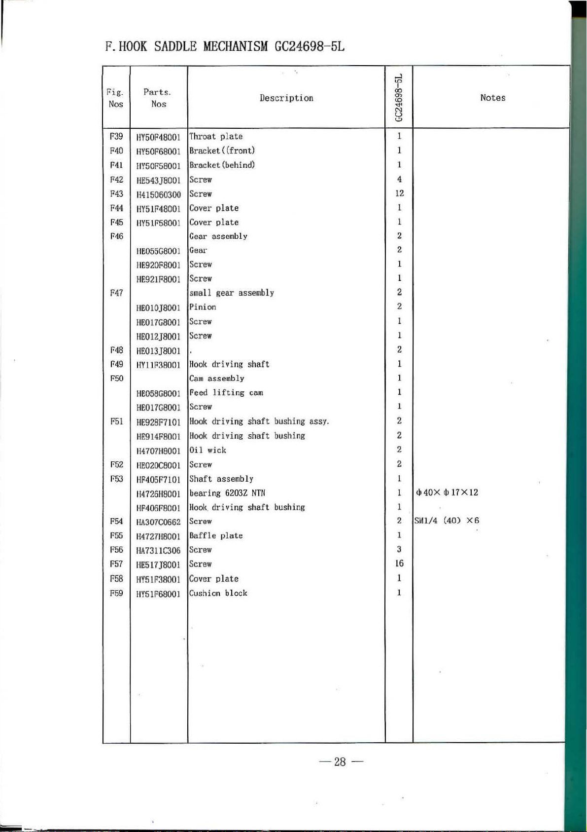
Page 31
r
F.
HOOK
Fig.
Nos
SADDLE
Parts.
Nos
MECHANISM
GC24698-5L
Description
.....l
lD
00
m
<0
"<t'
C';)
u
(.!)
I
Notes
1'39
F40
F41
fo42
F43
F44
F45
F46
F47
F48
F49
F50
F51
F52
P
53
F54
1755
F56
F57
F58
J759
11V50F'4800
IW50F6
HY50F5800l
HE543]8001
H415060300
HY51F48001
HY51F58001
IIE055
I I
E920F800
HE92IF8001
IIE010]8001
HE017G8001
HE012]8001
HE013J8001
HY11
HE058G8001
HE017G8001
HE928F710l
HE914F8001
H4707H8001
HE020C800
H
F40517710l
H4
726H8001
HF40617
IIA30
H4727118001
IIA7311C306
IIE517J8001
HY51F38001
HY
51F68001
1
8001
G8001
I
F38001
1
8001
7C0662
Throat
Bracket ((front) 1
sma
Pinion
Screw
Screw
Hool<
Cam
Feed
Hook
Oil
Screw
Shaft asse
bearing 62032
Hool<. driving shaft
Screw
Baffle p
Screw
Screw
Cover
C
plate
(behind) 1
ll gear
assembly
wick
ush
ion block
assemb
ly
driving
lifting
driving
driving
plate
shaft
cam
shaft
bushing assy.
shaft
bushing 2
mbl
y
NTN
bushing 1
lat
e 1
1
4
12
1
1
2
2
1
2
2
1
2
1
1
1
1
2
2
2
cb40X dll7Xl2
1
SMl/4
2
3
16
1
1
(40)
X6
-28
-
Page 32

G.HOOK
SADDLE
0 0
57
MECHANISM
,...A4
GC24698-5R
j
46
-29-
·~
57
Page 33

G.
HOOK SADDLE MECHANISM
P
art
N
os
s.
Description
Fi~.
N
os
GC24698-5R
e:3
I
00
Ol
tO
-.:1'
N
u
(.!)
N
otes
GO
. I
C02
G03
G04
G05
GOG
G07
GOB
G09
GlO
Gll
Gl2
G13
Cl4
GIS
G16
Gl7
Gl8
CI9
G20
G21
G22
G23
G2
4
G25
G26
G27
G28
G29
G30
G3
1
G32
G33
G34
G35
G36
G37
C38
11
Yl0F68001
HYllr98001
t1E053C80
IIY
HE0
IIY
0l
llF2800 1
18J8001
11
FOB
OO
1
IIE017J8001
IIE018J8001
HE019J8001
HE912F800
HE911F800
1
1
HYllrl8001
H
005004050
HE909F8001
HE524J8001
HE517]8001
HE517J800l
H
E521]8
001
IIE522]8001
HE
520J8
001
HY12F18001
H9017H800l
H720
6E800l
HYl
OF7
7101
HY10F88001
1141
5050160
H00
500
8050
IIY10F
98001
HY5
1F28001
HE533J8C01
IIE532J8001
HE517]8001
HE12318001
I-JE
535J8
001
IIE53
6]8001
HE045D800l
IIE0
21B800l
HYl2EL8001
HY
60P
48001
Hook shaft
supporter
Bushing
Screw
Dobbin
Oil
case opener lever hinge sha
pad
ft
Bobbin case opener level'
Locating stud 2
Oil
pad
Nut
Dobbin
!l
Dobbin
Washe
case opener lever link
ook
case opener
r
Screw
Sp~
ing
Scr
ew
Sc
rew
Hin
ge
Pin
Hinge
Hook
cover
Collar assy.
Collar
Screw
Clutch assy.
Clutch
Screw
Spring
Co
Fee
Supporter
washe
nnec
ting
d plate
rs
sha
set
plate
ft
bracket
Felt
Screw
Screw
Sq
uare block
Sc
rew
Washer
Nut
2
2
2
2
2
2
2
2
2
2
2
2
2
2
2
4
2
2
2
2
4
4
8
2
2
4
4
2
1
2
2
4
1
1
1
l
1
l
1
l
/32X32
15/64X28
L=6
-3
0 -
Page 34

G.
HOOK
Fig.
Nos
SADDLE
Parts.
Nos
MECHANISM
GC24698-5R
Descri ption
0:::
I
""
00
m
<D
-.:r<
N
u
<.!)
Notes
G39
G40
G41
G42
G43
G44
G45
G46
G47
G4
8
G4
9
GS
O
GS
l
52
G
GS:l
C54
G55
G56
G57
G58
G5
9
HY50F48001
IIY50F
6800
1
HY50F58001
HE54
3J8
001
~It!
15
060300
IW51F48001
HY51F
5800
l
HE05
5G800
1
HE920F
800
1
IIE921F8001
IIEOlOJ
8001
HE017G
800
1
HE012]8001
HE01
3J800
l
IWllF
3BOO
t
HE058G
8001
IIE017G8001
IIE
928F
7101
BA
7311
C30
6
H470711800l
IIE02
0C80
01
IIF40
5F7101
H47261l8001
HF406F8001
I
IA307
C0662
11472711
800
1
IIA7311
C30
6
IIE517]800!
IIY51F3
8001
HY51F
6800
l
Throat
pla
te
£lracket ((fron t) 1
Bra
cket (behind) 1
Screw
Screw
Cover
plate 1
Cover
plate
Gea
r ass
embly
Gear
Screw
Scr
ew
small gear assembly 2
Pinion 2
ew
Scr
Scr
ew
washer
llook
driving
Cam
assembly l
Feed
lift
sha
ft
ing cam 1
Screw
Ho
ok dri
ving sh
Hook driv
aft
bushing assy.
ing shaft bushing 2
Oil wick
Screw
Shaft
assemb
ly
bearing
Hook
6203Z
drivi
ng
NTN
sha
ft bus
hing
Screw
Baffle
plate
Screw
Screw
Cover plate
Cushion
block
l
4
12
1
2
2
1
1
1
1
2
1
1
2
2
2
1
1
1
2
I
3
16
1
1
(jJ
40
S
Ml/4
X
<h
17 X 12
(40) X6
-31-
.
Page 35

H.
THREAD
TENSION
REGULATOR
5
i
HANISM
MEC
28
4
~
~
3~
29 44.55
I
17~8
9
18~~7
14~~~
~~~22
19~
31~
.J
~/AS
0.
~
47~~
,
~
48
I 49
6>
~u
~24
o--
20
21
23
~~):j
58
. '
36-
cJ
59 i ..
c
~
30
~
33
)
"F
40~3839
o.Y? I
7"
~~1i
46
~
~
41
~
37
[!
, 43
60
=-=~-
1~
~
62
~
I
50·
'
1
~@
-~
51
I
~
~
42.56~
~
63
-32
-
Page 36

H.
THREAD
fo"ig.
P
Nos
TENSION
arts.
Nos
REGULATOR
MECHAN1SM
Description
<0
cb
en
<0
~
C'\1
u
t.:>
,....l
1.0
I I
00
00
en m
<0
<0
~
~
t.:>
cz::
1.0
~
C'\1
u
t.:>
No
tes
110
1 B
E904G8001
1102
HE905G8001
11005006080
11
03
H
OI!
HE
907G8001 Screw
I
I()[.
HE908G8001
H
106
08
E0480800
H
E934G800
II
E935G8001
II
E936G800
II
E937G800
II
E938G8001 Hol
l
1166
1
H07
11
~10 9
lllO
!HI
lll
1113 116651
1 Screw 1 1 l
L
l
1 Shaft
5688001
0800 I Lever
IIIII Jl11310300'10
1115
11664988001
1116
114090110080
1
117
H431040010
1118
1119
H6650B800
H6657B8001
1
H20
1121
H
22 116653B8001
23
H
1166558
8001 Spri
11
21 H6658B8001
II
11
11
1127 I lEO l9K8
11
1129
1130
H
1132
H33
1131
H35
E924G7101
25
26 IIE910G8001
00
28
IIE
912G800
IIE913G800
HE046C8001
31
HEOI2E8001
IIE914G8001
HE915G800
HE916G8001
HE018H8001
1
L Thread releasi
L Thread contro
1
1136 IIE931G8001
11
37
HE046C8001
1138
llr
205G8001
H
39 HE917G800
1140
HE022K8001
1141
HE
918G800
1
1 Thread contr
1142 HE919G8001
11
113
IIE
920G800
I Screw
Presser
oar
spri
ng (fl
at)
1 1 1
Presser bar spring (auxiliary) 1 l
Washer
I 1 1
1 1 1
Screw
Ca
m 1 1 1
Hold plate
ve
r 1 1 1
Le
d plate I
Washer
Screw
Shaft
Screw
Screw
Pin
Thread winder
wheel
1 I
I
1
1 1
l
1
1
I
1 1
1
1
4
4
1 1
2 2
2 2
1 I
1
l 1 1
4
2
2
Pin I 1 1
Pin
Spring
ng
2 2
2
1 1 1
I 1
Tire 1 1 l
Mounting
Thread tesion
Screw
Stop
Stop
Thread guide
Screw
Thread guide
Nut
Stopper
Screw
TJu
·ead ta.
Thread controller
Set.
Thr
plate 1
releas
ing discs
ng
pinOong)
ller
covering pl
ate
screw
screw
ke-up
spr
ing
spring stud
screw
oller
disc
ead controll
er
stud
1
2 2 2
I 1 I
I 1 1
1
l I
2 2 2
1 1 1
2 2 2
1
1 I
I
l
1
1 l
I 1
1
1
1 1 1
1 l
l I 1
1
1 1 S
1
S
M17
SM17
1
1
1
1
dJ
<IJ
l
SM1l/64 (32)
SMO. 1339
l
1
l
1
Mll
/64 (24) X 13
/64
(24)
2.
5X8
2.5Xl2
(36) X 3.
/64
(32)
X 8
X 6. 5
5
X 4
-33-
Page 37

H.
THREAD
Fig
.
Part
Nos Nos
TENSION
REGULATOR
s.
Descripti
MECHANISM
'f
00
0>
on
w
-.d'
N
u
(.!)
.....J
0::
1D
lD
I
00
00
0> 0>
w
<0
...,.
'<f'
N N
u u
(.!) (.!)
'
N
ote
s
H44
IIE921G
800
l
HE915G8001
H45
H46 HE922G8001
H47
lli!923G8001
l
lt\
31
H48
H49
H50 I 12
H51 HA3
H52
1~
53
1154
1155 I!F
H
56
H57
115
8 H
1159 H31
01307 05
HA310B0702
206130671
10B070l
HF206G7
101
HF208G8001
HF
209
G800
1
2lOG800l
HF211G80
01
HE033B8001
E03
2B8001
0880692
H60 H1!929GB001
II
H61
H62
E930G7101
HA30CC2030
TI1read
guide 1
2 2 2
1 1 1
releasing pin (long) l 1 1
4 2
tension releasing discs 2
2 1
2 1
1
Tension release lever 1
Thread
guide
Thread guide(lower)
Scr
ew
Oil
pad 1 1
Thread take-
up spri
ng
Stopper
Scr
ew
1 1
1 1 1
1 1
1
1
4 4
1
2
1
1
1
1
4
-34
-
Page 38
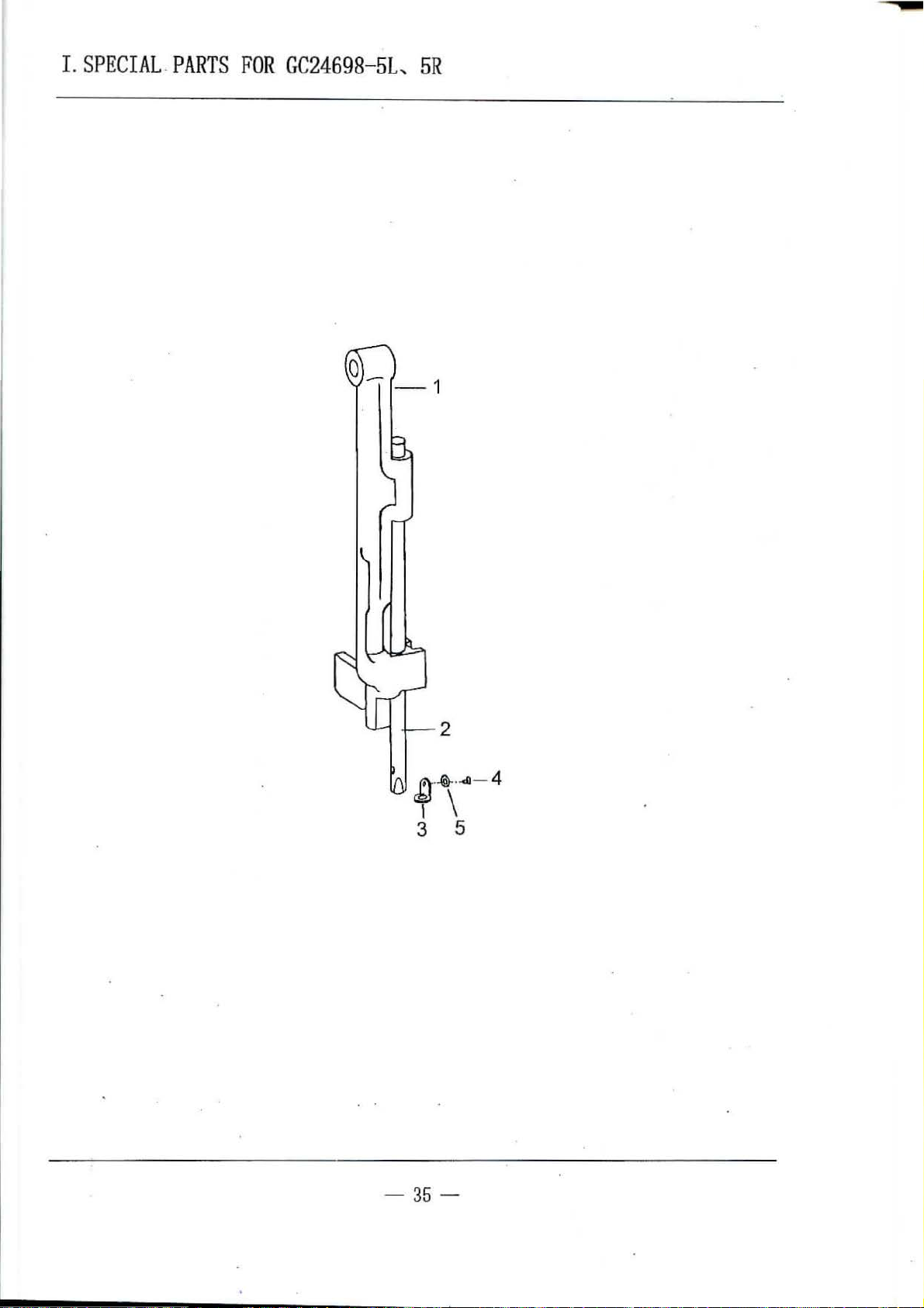
I
.SPECI
AL.PARTS
FOR
GC24698-5L,
5R
2
cD·-fr·.cG
I \
3 5
- 4
-
35-
Page 39

I.SPECIAL
Fig.
Nos
P
arts.
No
s
PARTS
FOR
GC24698-5L,
Descrip
tio
n
5R
....l
lf:) lf:)
I
00
0'>
lD lD
(';!
""
u u
<..::>
0:::
I '
00
0'>
N
""
<..::>
Notes
101
I02
103
!
04
T05
HF204D8001
llfo'205D
8001
llfo206D800
1 Needle bar
H4915J8001
ll005001025
Needle
Needle
et
scr
b8l·
bar
ew
Flat washer
guide bracket 1 1
l 1
threa
d guide
1 1
1
1
1
-
36-
Page 40

w
sp
ecifications
l/4
"'
3/8*
l/2"'
7/8*
3/4H
1'
1
1/4'
1 1/2"'·
1 3/4"'
-;)
Needle bar
(C08)
HE970D8001
HE971D8001
HE97208001
HE97308001
HE9080800
HE97408001
HE975D8001
HE976D8001
HE977D8001
1
.
Needle
plate
(E39)
HY12F48001
HY12F58001
HY12F68001
HY12F78001
HYllF78001
HY12F88001
HY
12F
98001
HY13F08001
HY13F18001
Vibrat ing
pres
ser
foot
(C41)
HE962D8001
HE96308001
HE964-D800
HE965D8001
HE928D8001
HE966D8001
HE96708001
HE9680
800
HE969D8001
1
1
Lifting
presser
(C25)
HE95408001
HE95508001
HE956D8001
HE95708001
HE91908001
HE958D8001
HE95908001
HE96008001
HE961D8001
foot
Feed
dog
(E35)
HY13El8001
HY13E2800
HY13E380
1
01
HY13E48001
HY11E08001
HY13E58001
HY13E68001
HY13E78001
HY13E8800
1
Bracket
(E40)
HY13F2800l
HY
13F38001
HY13F48001
HY13F58001
HY11F48001
HY13F68001
HY13F7800l
HY
13F88001
HY13F9
8001
Plate
(E41)
HY14F08001
HY14F18001
HY14F28001
HY14F38001
HYllF58001
HY14F48001
HY14F58001
HY14F68001
HY14F78001
Cover
plate
(E45)
HY14F8800
HY14F9800l
HY15F08
001
HY15Fl800
HY12F28001
HY15F28001
HY15F3800
HY15F48001
HY15F58001
1
1
1
t-...(
(/)
-o
t:T)
(")
H
>
r
"'"0
::>
::::\:1
>-3
en
'"r:l
0
::::\:1
c;1
0
t-.:l
~
0')
c.o
co
I
0">
i
•
--
Page 41

K.ACCESSO
RIES
I
2
I \ I I \ I
3 4 5 6 7 8
$)
15.
21
19
-
38-
Page 42
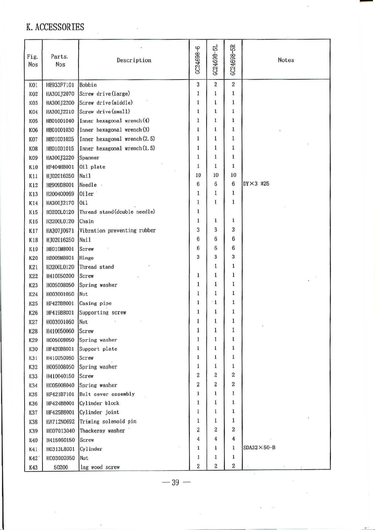
K.ACCESSORIES
Fi
g.
Parts
.
No
s
1<
01
[(Q
2
1<03
K
04
1(05
1
(06
K07
K08
K09
K
lO
Kll
1<12
Kl3
Kl4
1(15 H32
1(16
Kl7
K18
IU
9
K2
0
K21
K22
K23
K24
K25
K2
6
K27
K2B
1(
29
K30
J<:H
1<32 H005008050
({33
K34
K35
1
(36
K37
K38
K39
1{40
K41
K4
2'
1(4
3
Nos
HE933F7101
1
1/\300}2070
Ht\300}2200
Hi\300}22
11801001
HB01001030
HB010010
HB0100101
Hi\300}2220
HF404H8001
11
]02
016250
llfl909D8001
H2
004000
Ht\300]2170
00L0120
113200L0120
HA~07J067
HJ02016
HE010M8001
HE009M800
113200L0120
114
10050200
B005008050
H0030010
HF
427B8001
HF419B80
H003001060
H4l0050060
H0050080
IW420B8001
H4
1005
Bobbin
Scr
ew
Scr
ew dri
Screw
10
Inner h
040
Inner hexagonal
Inner
25
Inner hexag
5
Spa
nner
Oil
plate
Nail
Needle
Oiler ·
69
Oil
Thread
Chain
Vibration preventing ru
1
Nail
250
Scr
ew
Hinge
1
Th
read stand
Scr
ew
Spring washer
50
Nut
Cas
ing pipe
S
uppo
01
rting
Nut
Scr
ew
Sp
ring
50
Support
0060
Screw
Spring
11111
0040150
H005008040
I
IF42
1B7101 Belt cover asse
BP424B800l
IIF
425
B8001
llfi712N06
H007013QilQ Thacl
1'1415060150
11
0313L800
li003002050
50200
Screw
Spring wash
Cy
Iinder block
Cy
lind
Triming solenoid pin
92
<el·ay
Screw
Cylinder
1
Nut
lag
woo
dri
drive(srnal
exago
hexagonal
sta
washer
washer
er joint
d sc
....J
ID
tp
00
00 00
Ol
Ol Ol
Description
<..0
'<:!'
N
u
(.!)
<..0
'<:!'
N N
u
(.!)
3
ve
(large) 1 1 1
ve(middle) 1 1
l 1 1
1 1 1
1 1 1
1
1 1 1
nal
onal
l)
wrench
(4)
Wl·ench(3)
wren
ch(2.5)
wrench
(1.
5)
1 I
1 1
10 10 10
6
I 1 1
1 1 1
nd(doub
le
need
le)
1
1 1
bber
3
6
6 6
3 3
1 1
1 1
1 1
1 1
scre
w
1
1
1 1
1 1
plate
1 1
1 1 1
1
2 2
er
mbly
2 2
1 1
1
1
1
washer
rew
2 2
4 4 4
1 1 1
1 1
2 2 2
ll::
'f
I
~
t5
2 2
1
6 6
3 3
6 6
1
1 1
1 1
1 1
1
1 1
1
1
1
I
1
DYX3
L
6
3
1
1
1
1
1
1
L
1
2
2
1
l
1
2
SDA32X5G-B
1
U26
Not
es
- 3
9-
Page 43
.,
J
j
SHANGHAIHUIGONG
ADD: 1418, Yisb
Zip
Code: 201103
Overseas Business:
E-mail: bigblcad@online.sb.cn
The clescrl
pllon
ao
Road,
TEL:
covcrecl
Shanghai,
86-21-64853303 FAX: 86-21-64854304
lu
Hili
mnmml
N0.3
SEWING MACHINE
China
http:
//www .highlead.com.cn
is
subject
to chnuge ror Improvement or the couunoclity witJtout uofice
FACTORY
-
.j
2008.4. Printecl
 Loading...