

Page 1

GC24698-25L/-25R
Long Arm Post Bed Compound Feed Split
Lockstitch Sewing Machine
Instruction Manual
Parts Catalog
SHANGHAI HUIGONG NO.3 SEWING MACHINE FACTORY
Page 2

----- CONTENTS -----
Preparation for operation···············································································································1
1. Safety precautions ·································································································································1
2. Precaution before Starting Operation ·································································································1
3. Precaution for Operating Conditions ··································································································1
Cautions on use········································································································································· 1
1. Lubrication ············································································································································1
2. Cautions on operation ··························································································································2
Operation ·····················································································································································2
1. How to attach needle ·····························································································································2
2. How to wind the lower thread ··············································································································2
3. Selection of Thread ····························································································································· 2
4. How to route the upper thread ············································································································3
5. Adjustment of stitch length and reverse sewing ·················································································3
6. Balance of thread tension ·····················································································································3
7. Upper thread tension ····························································································································4
8. Adjustment of pressure of presser f oot ·······························································································4
9. Timing between rotating hook motion and needle motion ································································4
10. Adjustment of Feed dog height ············································································································4
11. Walking foot and presser foot vertical stroke adjustment ································································5
12. Safety clutch device ·······························································································································5
Specifications ················································································································································6
PARTS LIST ·················································································································································7
A. ARM BED MECHANISM ···················································································································7
B. THREAD TENSION REGULATOR MECHANISM ·······································································9
C. ARM SHAFT MECHANISM ············································································································11
D. PRESSER FOOT MECHANISM ·····································································································13
E. THRED TAKE-UP LEVER & NEEDLE BAR MECHANISM ·····················································16
F. STICH REGULATOR MECHANISM ·····························································································19
G. LOWER AND FEEDING SHAFT MECHANISM ··········································································21
H. FEED BAR MECHANISM ················································································································24
I. HOOK SADDLE MECHANISM ···································································································· 26
J. OIL LUBRICATION MECHANISM ·······························································································28
K. ACCESSORIES ··································································································································30
L. PNEUMATIC CONTROL UNIT ······································································································33
Page 3
Preparation for operation:
1. Safety precautions:
1) When turning the power on, keep your hands and fingers away from the area around/under the needle
and the area around the pulley.
2) Power must be turned off when the machine is not in use, or when the operator leaves the seat.
3) Power must be turned off when tilting the machine head, installing or removing the “V” belt, adjusting
the machine, or when replacing.
4) Avoid placing fingers, hairs, bars etc. near the pulley, “V” belt, bobbin winder pulley, or motor when the
machine is in operation.
5) Do not insert fingers into the thread take-up cover, under/around the needle, or pulley when the machine
is in operation.
6) If a belt cover, finger guard, eye guard are installed, do not operate the machine without these safety
devices.
2. Precautions before starting operation:
power on.
1) Never operate the machine before filling the machine’s oil pan.
2) When a new sewing machine is first turned on, verify the rotational direction of the pulley with the
3) Verify the voltage and phase (single or three) with those given on the machine nameplate.
3. Precautions for operating conditions:
1) Avoid using the machine at abnormally high temperatures(35℃ or higher)or low temperatures(5℃ or
lower).
2) Avoid using the machine in dusty conditions.
Cautions on use:
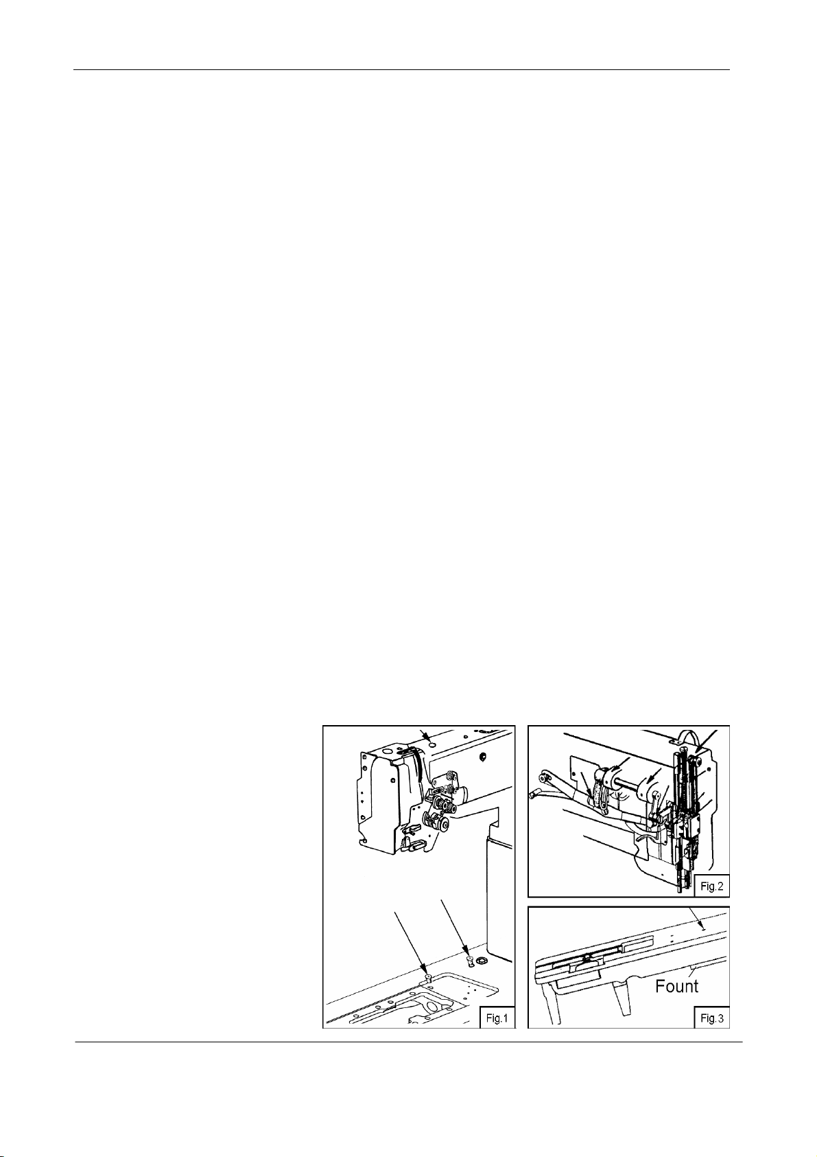
1. Lubrication (Fig.1, Fig.2)
When a new sewing machine is
used for the first time, or sewing
machine left out of use for a long time is
used again, replenish a suitable amount
of oil to the portions indicated by arrow
in the fig.
Note: Filling the oil to the fount
timely (Fig.3). Use white spindle oil.
— 1 —
Page 4
2. Cautions on operation
1) When the power is turned on or off, keep foot away from the pedal.
2) It should be noted that the brake might not work when the power is interrupted or power failure
occurs during sewing machine operation.
3) Periodically
clean the machine.
Operation
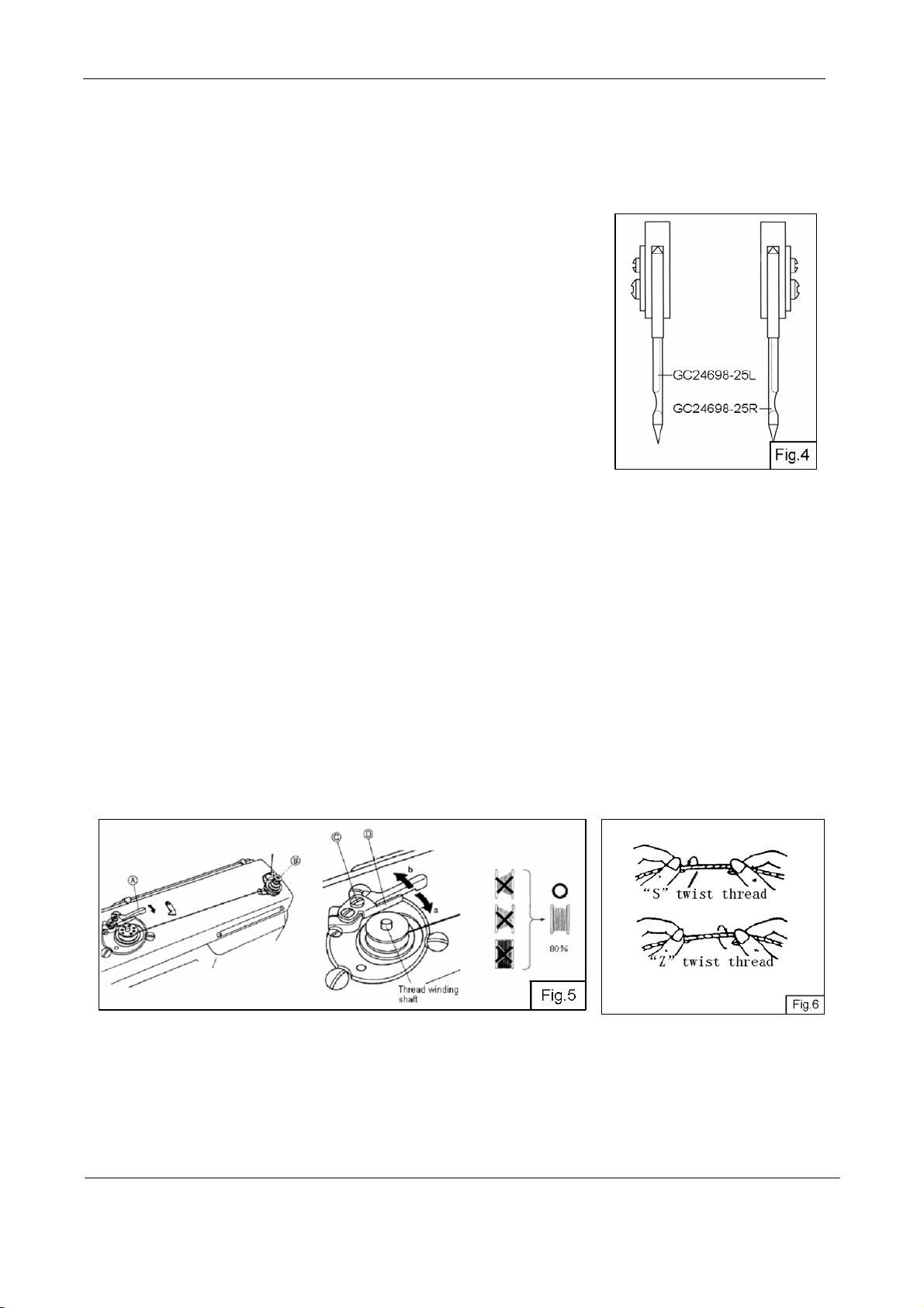
1. How to attach needle (Fig.4):
Note: Before attach needle, be sure to turn off the power.
Loosen the needle clamping screw;Hold the needles so that the two
needles side with the long grooved (faces each other), and insert it as deeply as
it will go into the needle clamping holes, tighten screws.
2. How to wind the lower thread (Fig.5):
Strength of winding:Particularly in the case of nylon or polyester thread, wind the bobbin loosely.
(1) Press the bobbin onto the thread winding shaft.
(2) Pass the thread for winding thread as shown in the figure, and wind the end of the thread clockwise
around the bobbin several times, then wind the thread on the thread adjuster side counter-clock wise several
times.
(3) Press lever A in the direction of the arrow, and start the sewing machine.
(4) The operation will automatically stop when winding is completed.
(5) Adjustment of thread winding strength, Adjust with the thread adjuster nut B.
(6)Adjustment of thread winding amount, Adjust by loosening screw C and moving the adjustment plate D
a. The thread winding amount will decrease when moved in the direction of a.
b. The thread winding amount will increase when moved in the direction of b.
3. Selection of Thread(Fig.6):
It is recommended to use “S” twist thread in the left needle (Viewed from front), and “Z” twist thread in the
right needle.
When discriminate use of needle thread is impossible, use “Z” twist thread in the needle. For bobbin thread,
“S” twist thread as well as “Z” twist thread can be used.
— 2 —
Page 5
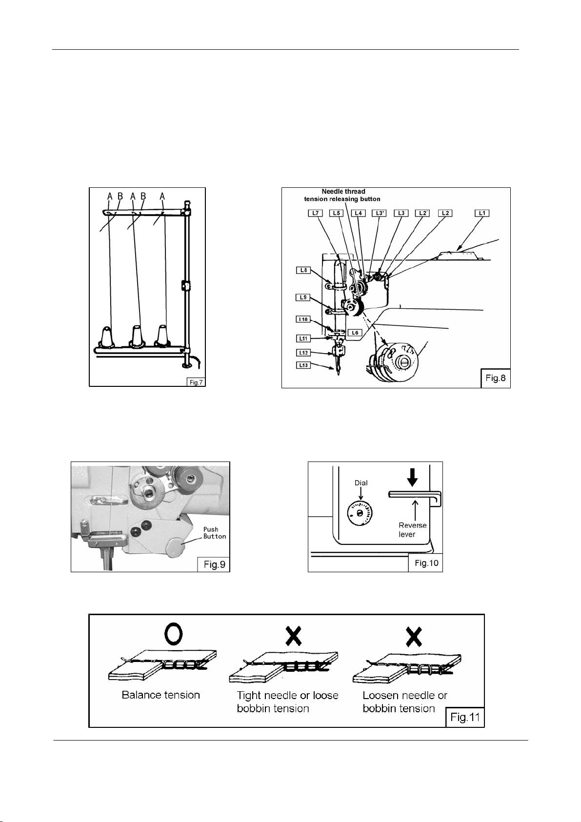
4. How to route the upper thread (Fig.7, Fig.8):
1) Pass each upper thread through thread guide A
Note: when thin slippery thread (polyester thread for example) is used pass the thread through thread
guide B as show in Fig.7
2) With the take-up lever located at the upper most position, pass each thread in the order in Fig.8.
Note: Pressing the upper thread loosening button, the upper
thread can be pulled out easily.
Adjustment of stitch length and reverse sewing
5.
1) Rotate the stitch length adjusting dial to change the stitch length
2) If the reverse lever/push-button is depressed, reverse sewing will take place.
(Fig.9 Fig.10):
6. Balance of thread tension (Fig.11):
— 3 —
Page 6
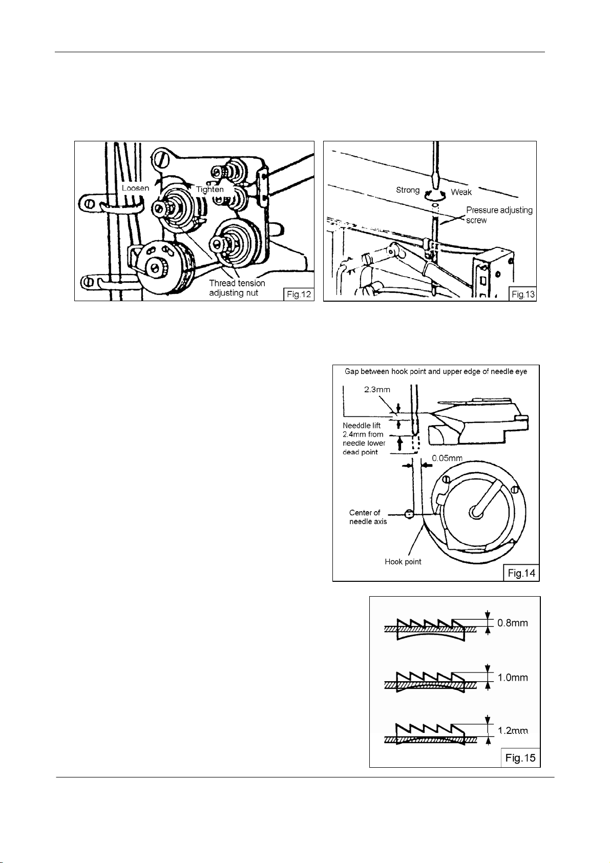
7、Upper thread tension (Fig.12):
1) The upper thread can be adjusted based on the lower thread tension.
2) Adjustment can be done by rotating the thread tension nut.
8. Adjustment of pressur
1) Pressure should be adjusted according to the material
to be sewn.
2) Turning the pressure adjusting screw to adjust the
pressure of presser foot
e of presser foot (Fig.13):
9. Timing between rotating hook motion
and needle motion (Fig.14):
1) Set stitch length to “6”;
2) When needle is lifted 2.4mm from the lower dead
point, the following position relationship should be
maintained:
·The upp
the hook point
·The hook point should be located at the center of
needle axis.
· Gap between
be 0.05 mm
er edge of needle eye should be 2.3mm below
the hook point and the side face of needle should
10. Adjustment of Feed dog height (Fig.15):
Height of feed dog should be adjusted for individual fabrics with the
following cautions:
1) Fabric will be damaged if the feed dog extends too high or
pressure of presser foot is too large
2) Even stitch length cannot be assured if the feed dog is too low
or pressure of presser foot is too small
— 4 —
Page 7
3) Feed dog height should be measur ed at the point wher e the needle
is at the top position.
For light fabric: Approx 0.8mm
For usual fabric: Approx 1.0mm
For heavy fabric: Approx 1.2mm
Adjustment procedure:
1) Lay down the machine bed toward the other side;
2) Turn the balance wheel by hand stop when the feed dog is raise to its highest position from the surface of
needle place;
3) Loosen the Screw and adjust the height of the feed dog;
4) After adjusted, tighten the screw.
The feed dog height is factory-adjusted to 1.2mm
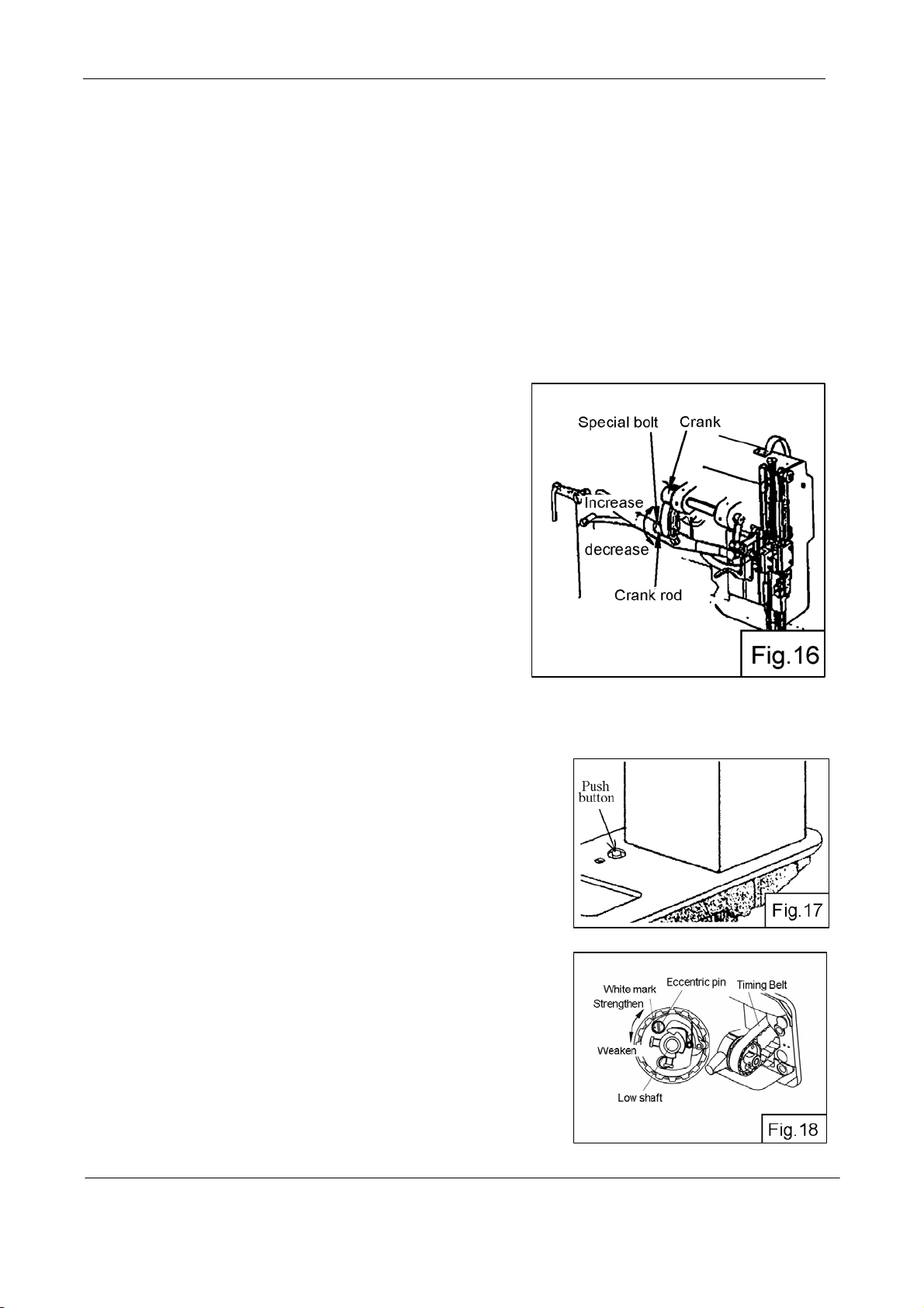
11. Walking foot and presser foot vertical
stroke adjustment (Fig.16):
When fabric with l
arge elasticity is sewn, or when thickness
of fabric changes, the vertical stroke (movable range) of the
presser feet should be adjusted as follows:
1) Loosen the special bolt;
2) The vertical strokes of presser feet become minimum
when the crank rod is moved downward and set;
3) The vertical strokes of presser feet become minimum
when the crank rod is moved upward and set;
4) After the adjustment, tighten the special nut.
The vertical strokes of presser feet can be adjusted within a range from 2mm to 6mm.
12. Safety clutch device (Fig.17, Fig.18)
Safety clutch device is installed to prevent the hook and cog belt
from damage in case the thread is caught into the hook when the
machine is loaded abnormally operation.
1) Function of safety clutch:
A. When the safety clutch acts, the cog belt pulley will be unloaded.
Then the rotation of hook shaft will stop. The arm shaft only will
rotate. Stop the operation of machine.
B. Clean t
C. Turn the cog belt hub by hand, and check whether the hook
shaft rotates lightly and properly, place the clutch device as follows.
2) How to set the safety clutch (Fig.18)
A. While pressing down the push button on the opposite side of
bed by left hand, turn the balance wheel slowly by right hand away
from you;
B. The ba
balance wheel more firmly;
he thread thoroughly which is caught into the hook.
lance wheel will stop by the gear plate, but turn the
— 5 —
Page 8
C. Release the push button, the safety clutch device is set.
3) Force applied to the safety clutch (Fig.18)
A. The force applied to the safety clutch is the smallest when the mark of eccentric pin faces the center of
the lower shaft. The force proportionally increases as the mark faces the outside;
B. To adjust the force slide the timing belt, loosen the set screw, and turn the eccentric pin;
C. After the adjustment, tighten the set screw.
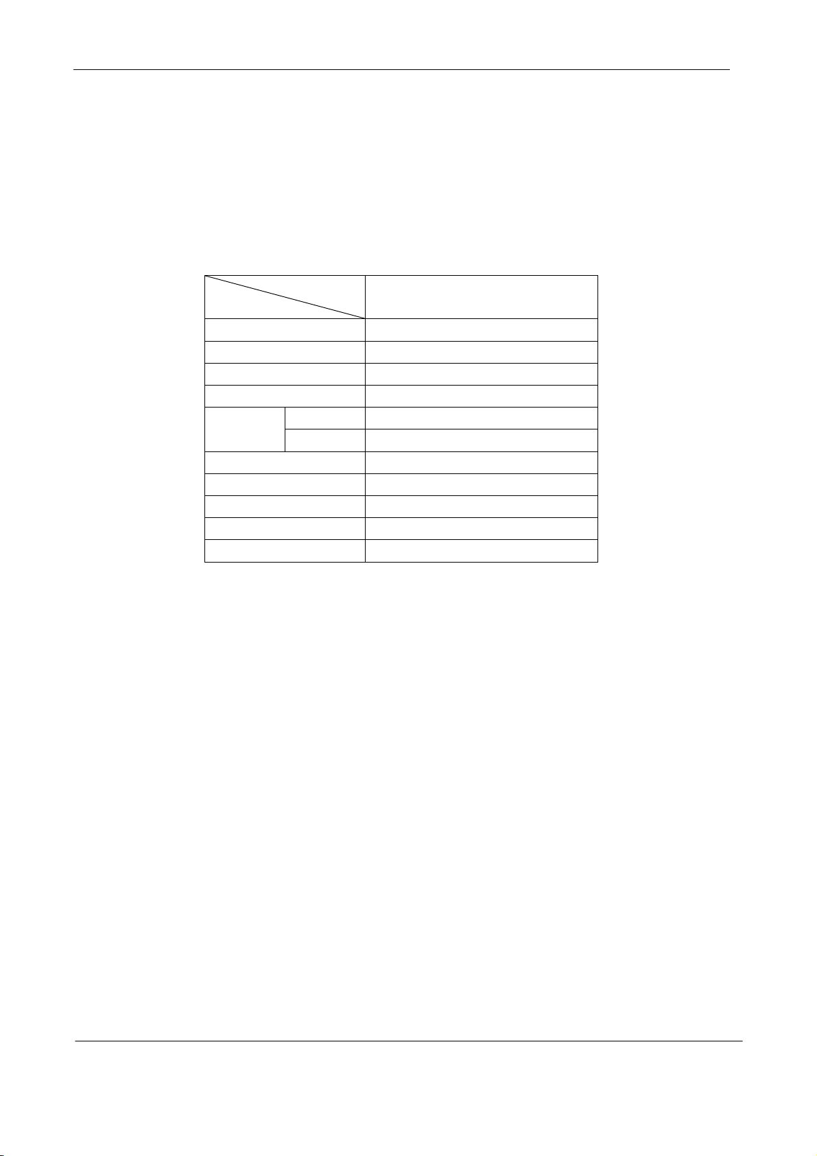
Specifications:
Model
Spec
Material weight Medium Heavy material
Max. sewing speed 1200rpm
Stitch length 0-7mm
Needle bar stroke 33.4mm
By hand 8mm Presser
foot stroke
By knee 16mm
Alternating movement 2-6mm
Stitch-length adjusting Dial type
Alternating movement Automatic
Needle DP×17(22#--24#)
Motor Servo Motor 550W
GC24698-25R/GC24698-25L
— 6 —
Page 9
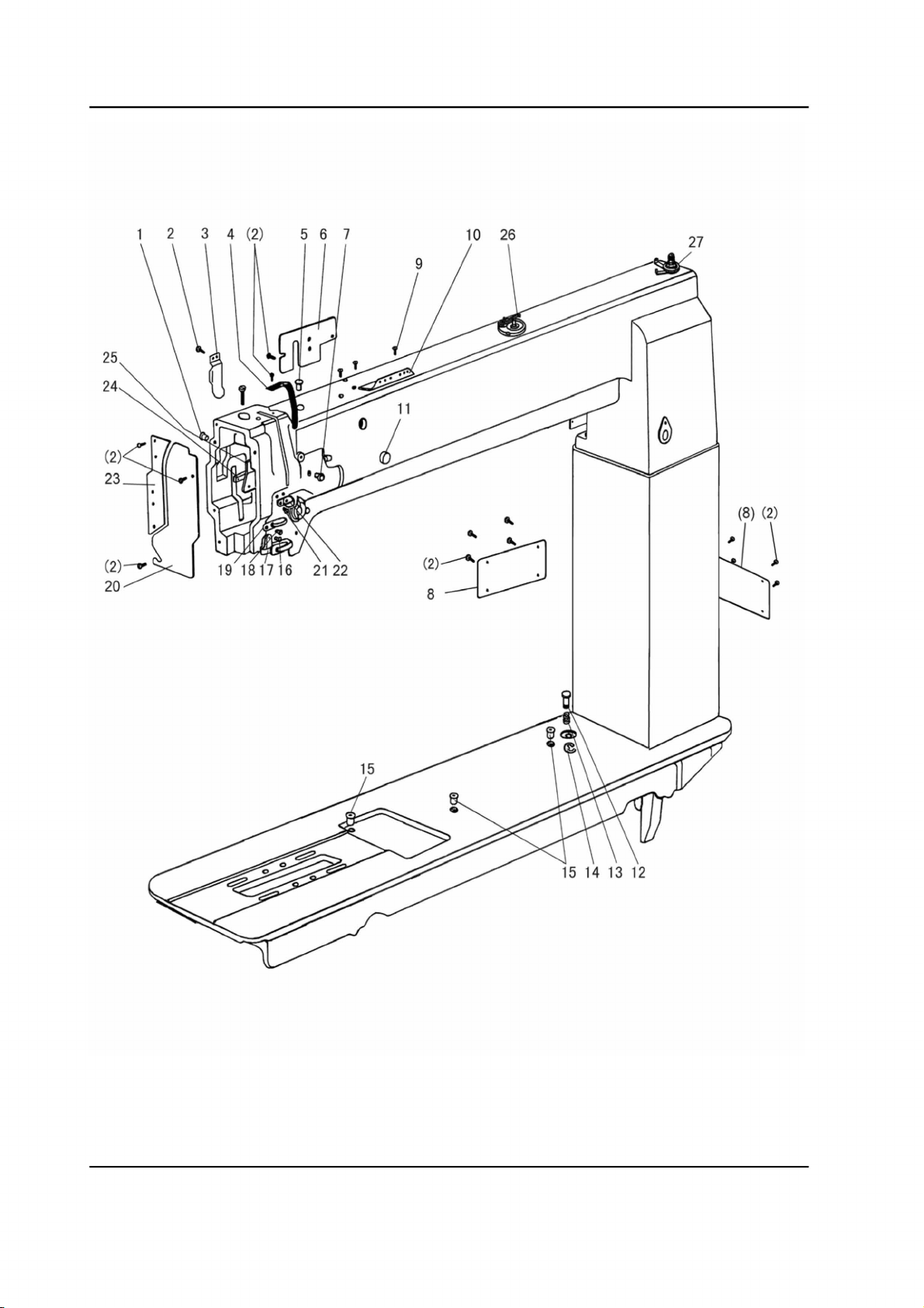
A. ARM BED MECHANISM
25
2.4
2 3 4
(2)
21
2.2
10
'
'
(2l
-'~
.·.
·
.....
8~
(8}
(2)
:
\
— 7 —
Page 10

A. ARM BED MECHANISM
Fig.
No.
A01 HA300B2090
A02 HA300B2170
A03 H4716B8001
A04 H4717B8001
A05 H4715B8001
A06 H4718B8001
A07 H2000B2010
A08 H7117B8001
A09 HA700B2060
A10 H2400B2100
A11 HA307B0673
A12 H4715H8001
A13 H4714H8001
A14 H007013050
A15 H2000M0090
A16 H3200B2100
A17 H3212B0066
A18 H3000D2160
A19 H4726B8001
A20 H4727B8001
A21 H2400B2080
A22 H2400B2070
A23 H4730B8001
A24 H2400B2060
A25 H3200B2060
A26 H7007D7101
A27 H7014D7101
Part No. Description
Rubber plug
Screw
Oil guide plate
Thread take-up cover
Rubber plug
Arm side cover (left)
Rubber plug
Arm side cover
Screw
Thread guide
Rubber plug
Push button
Spring
E-type ring
Cap
Screw
Thread guide
Screw
Thread guide
Face plate
Screw
Thread guide
Guide mounting plate
Spacer
Oil guide plate
Bobbin winder
Down-lead complete
Remarks
GC24698-25L
GC24698-25R
22
15 15 SM11/64(40)×9
11
11
11
11
11
22
2 2 SM11/64(40)×8
11
11
11
11
11
33
11
11
11
11
11
22
11
11
11
11
11
11
SM9/64(40)×6.5
SM9/64(40)×4.5
SM3/16(28)×12.1
— 8 —
Page 11
B. THREAD TENSION REGULATOR MECHANISM
— 9 —
Page 12

B. THREAD TENSION REGULATOR MECHANISM
Fig.
No.
B01 H2504C6510
B02 H3221B3142
B03 H3221B6812
B04 H4705C8001
B05 H4706C8001
B06 HA7311C306
B07 H4707C8001
B08 H007013050
B09 H3221B6820
B10 HA300C2030
B11 H3221B6810
B12 H4708C8001
B13 H4709C8001
B14 H3221B0683
B15 HA112B0693
B16 H3221B0684
B17 HA710B0671
B18 H3221B0682
B20 HA106B0676
B19 H3306B0661
B21 HA310B0702
B22 H4710C8001
B23 HA115B7010
B24 HA310B0701
B25 HA310B0705
B26 H3221B6817
B27 H3221B0686
B28 H32481B721
B29 H32481B621
B30 H32481BE21
B31 H4713C8001
B32 H32481BD21
B33 H4804C8001
B34 H4805C8001
B35 H3230K0751
B36 H3221B6817
B37 H4769E8001
B38 H3200B2100
B39 H3221B6819
Part No. Description
Screw
Tension releasing plate
Tension releasing spring
Screw
Lever
Screw
Mounting plate
E-type ring
Mounting plate
Screw
Nut
Spring
Push button
Thread tension stud
Thread tension disc
Spring
Thumb nut
Pin
Screw
Thread guide
Tension releasing disc
Spring
Thumb nut revolution stopper
Thumb nut
Thread tension disc
Pin
Thread tension stud
Thumb nut
Take-up spring guide
Plate complete
Thread take-up spring
Plate complete
Thread tension stud
Thread tension stud
Screw
Pin
Pin
Screw
Stopper
Remarks
GC24698-25L
GC24698-25R
2 2 9/64(40)×3
11
11
11
11
1 1 9/64(40)×7
11
1 1 GB/T896 5
11
2 2 11/64(40)×8
22
11
11
1 1 11/64(40)×14
22
11
11
22
1 1 9/64(40)×6
11
11
11
11
11
22
11
1 1 1/4(40)×23
11
11
11
11
11
1 1 9/64(40)×2.9
1 1 1/4(40)×14.5
1 1 11/64(40)×10
11
11
1 1 9/64(40)×6.5
11
— 10 —
Page 13

C. UPPER SHAFT MECHANISM
t------18
(10)
31
30
29
28 27 26
— 11 —
Page 14

C. UPPER SHAFT MECHANISM
Fig.
No.
C01 HA307C0662
C02 H33111C104
C03 HA105D0662
C04 HA100C2060
C05 HA100C2070
C06 H4708D8001
C07 H32111B104
C08 H32111B204
C09 H7004D8001
C10 H3205C0661
C11 HA113F0684
C12 H3205C1021
C13 HA100F2130
C18 H7104D8001
C19 HA104F0654
C20 H4713D8001
C21 H4714D8001
C22 H4716D8001
C23 H007013025
C24 H4717D8001
C25 H4718D8001
C26 H4719D8001
C27 H4715D8001
C28 H4720D8001
C29 H4721D8001
C30 H4722D8001
C31 H4723D8001
C32 H007009300
C33 HA700R0060
C34 HA700R0050
C35 HA700R0040
C36 H4928L8001
C37 HA700R0030
C38 H4930L8001
C39 HA110D0672
C40 H4931L8001
C41 HA703R0067
C42 HA703R0065
B39 H3221B6819
Part No. Description
Set screw
Crank
Set screw
Screw
Screw
Set screw
Felt
Arm shaft bushing (left)
Arm shaft
Spring flange
Screw
Pulley
Screw
Cog belt
Screw
Link
Pin
Spring
E-type ring
Link
Pin
Link
Pin
Bushing
Screw
Pulley
Screw
Retaining ring C-type
Washer
Support spring
Spacer B
Speed command disk F20 (up)
Spacer A
Speed command disk F11 (down)
Screw
Pulley (complete)
Washer
Detector bracket (complete)
Stopper
Remarks
GC24698-25L
GC24698-25R
11
11
11
11
11
1 1 SM1/4(24)×13
11
11
11
33
33
11
11
11
11
11
11
11
11
11
11
11
11
11
11
11
22
1 1 GB/T894.1 30
11
11
11
11
22
11
22
11
11
11
11
SM1/4(40)×6
SM1/4(40)×4
SM9/32(28)×13
SM9/32(28)×14
SM15/64(28)×8.5
SM15/64(28)×14.5
SM15/64(28)×10
SM15/64(28)×10.5
SM15/64(28)×4.5
SM15/64(28)×12
— 12 —
Page 15

D. PRESSER FOOT MECHANISM
— 13 —
Page 16

D. PRESSER FOOT MECHANISM
Fig.
No.
D01 H4705E8001
D02 H4707E8001
D03 H0030580608
D04 H4706E8001
D05 H4709E8001
D06 H3115F0671
D07 H2013J0065
D08 H2014J0066
D09 H2000J2100
D10 H4713E8001
D11 H20111C106
D12 H007009250
D13 H4714E8001
D14 HA307C0662
D21 H3100G2170
D22 H4730E8001
D23 H4729E8001
D24 H4727E8001
D25 H4728E8001
D26 H3100G2130
D27 H4726E8001
D28 H4725E8001
D29 HA111G0683
D30 H4723E8001
D31 H4754E8001
D32 H4744E8001
D33 H3200E2020
D34 H4746E8001
D35 H4768E8001
D36 H2404I0034
D37 H4748E8001
D38 H4767E8001
D39 H4752E8001
D40 H4749E8001
D41 H0207E8001
D42 H2004J0655
D43 H4717E8001
D44 H4718E8001
D45 H2004J0662
D46 H4719E8001
D47 HA100E2150
D48 H4722E8001
D49 H4721E8001
Part No. Description
Feed lifting rock shaft
Bushing
Nut
Set screw
Crank
Screw
Washer
Connecting rod
Screw
Oil wick
Holder
C-type ring
Eccentric
Screw
Screw
Lever spring
Screw
Twist spring
Knee lifting lever
Screw
Nut
Screw
Screw
Guide
Presser bar
Bushing
Screw
Spring bracket
Thread releasing plate
Screw
Lift lever
Spring
Bracket
Screw
Bell crank
Screw
Roller
Screw
Screw
Link
Screw
Washer
Bell crank guide
Remarks
GC24698-25L
GC24698-25R
11
22
1 1 (M6×0.75)
2 2 SM1/4(24)×7
11
11
11
11
1 1 M6(0.75)×24
11
11
11
11
22
1 1 SM1/4(24)×17
11
11
11
11
1 1 SM1/4(24)×7
11
11
2 2 SM11/64(40)×12
11
11
11
1 1 SM1/8(44)×9
11
11
11
11
11
11
1 1 SM11/64(40)×8.5
11
11
11
11
1 1 SM1/4(40)×5
11
22
22
11
SM1/4(28)×16
SM1/4(40)×6
SM15/64(28)×79
SM1/4(24)×19
SM9/64(40)×8.5
SM3/16(28)×10
SM11/64(32)×6
SM11/64(40)×10
— 14 —
Page 17

D. PRESSER FOOT MECHANISM
Fig.
No.
D50 H4753E8001
D51 H4708D8001
D52 H7905E8001
D52 H7105E8001
D53 HE204I8001
Part No. Description
Screw
Set screw
Lifting presser
Lifting presser
Finger gusrd
Remarks
GC24698-25L
GC24698-25R
1 1 SM11/64(40)×17.5
2 2 SM1/4(24)×13
1
1
11
— 15 —
Page 18

E. THRED TAKE-UP LEVER & NEEDLE BAR MECHANISM
2 3 4
56
7 8 9
10
11
12
13
48
47
31
32
— 16 —
Page 19

E. THRED TAKE-UP LEVER & NEEDLE BAR MECHANISM
Fig.
No.
E01 H24211DN05
E02 H4706F8001
E03 H4707F8001
E04
E05
E06
E07
E08
E09
E10
E11
E12
E13
E14
E15
E16
E17
E18
E19
E20
E21
E22
E23
E24
E25
E26
E27
E28
E29
E30
E31
E32
E33
E34
E35
E36
E37
E38
E39
E40
E41
E42
E43
Part No. Description
HA100C2020
H24211DN05
H24211DM05
H3504B0651
H2405D1112
HA110D0672
H24211D405
H24211D305
H2405D0662
H4716F8001
H4717F8001
H4719F8001
H32111D304
H4721F8001
H3204D6513
H4722F8001
H32111D604
H4806F8001
H4725F8001
H3400C2020
H3200I2030
H3400C2010
H4726F8001
H4753E8001
H4728F8001
H4729F8001
H4730F8001
H3410C301P
H3406C0671
H3406C0672
H4734F8001
H3204B0652
H602040240
H7004F8001
H7107F8001
H2012N0652
H7108F8001
H32311D406
H7104F8001
H7105F8001
Oil wick
Needle bar guide bracket stud
Screw
Set screw
Oil wick
Thread take-up lever support stud
Thread take-up lever
Thread take-up slide brock
Screw
Oil wick
Plug
Needle bar crank pin
Oil wick
Needle bar connecting link
Needle bar rock frame
Screw
Washer
Felt
Needle bar connecting stud
Screw
Needle bar
Vibrating presser bar
Bolt
Washer
Needle bar guide
Vibrating presser bar link
Screw
Vibrating presser bar guide
Spring
Vibrating presser spring guide
Square block
Screw
Needle bar vibrating crank(left)
Washer
Bushing
Taper pin
Needle bar vibrating shaft
Nut
Screw
Screw
Oil wick
Needle bar vibrating crank(right)
Connecting link
Remarks
GC24698-25L
GC24698-25R
11
11
1 1 5/16(28)×10.4
1
1
15/64(28)×10
1
1
1
1
1
1
1
1
1
1
15/64(28)×12
1
1
1
1
1
1
1
1
1
1
1
1
6
6
3/32(56)×4
2
2
1
1
1
1
1
1
9/64(40)×8.5
1
1
1
1
121
11
11
11
2 11/64(40)×17.5
1
1
1
1
1
1
1
1
1
1
15/64(28)×10
1
1
1
1
2
2
1
1 GB/T117 4×24
11
11
1
1 1/4(24)×16
1
1 5/16(24)×5
1
1
1
1
1
1
— 17 —
Page 20

E. THRED TAKE-UP LEVER & NEEDLE BAR MECHANISM
Fig.
No.
E44 H3129F0693
E45 HA100C2170
E46 H3129F0691
E47 H7106F8001
E48 HA700F2100
Part No. Description
Thread guide
Screw
Screw
Vibrating presser foot
Screw
Remarks
GC24698-25L
GC24698-25R
11
1 1 1/8(44)×4.5
1 1 3/32(56)×2.5
11
1 1 11/64(40)×7
— 18 —
Page 21

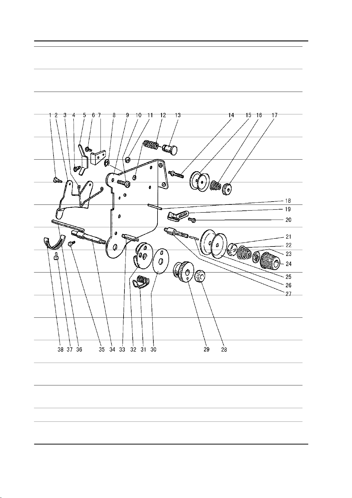
F. STICH REGULATOR MECHANISM
2 3 4 5 6 7 8
34
33 32
31
30
29 28 26
25 24 23 22
21
20
19 18
13
~16
~17
— 19 —
Page 22

F. STICH REGULATOR MECHANISM
Fig.
No.
F01 H4706G8001
F02 HA113F0684
F03 H3200F2020
F04 H7104G8001
F05 HA100G2070
F06 HF30G78001
F07 HA720F0687
F08 HA700F2030
F09 HF30G58001
F10 HA800F2020
F11 H3207F0672
F12 HA100F2110
F13 H7105G8001
F14 H4906G8001
F15 H4710G8001
F16 H3200F2050
F17 HA300C2030
F18 HA109F0673
F19 HA720F0685
F20 H7107G8001
F21 HA7421F120
F22 HA720F0683
F23 HA720F0687
F24 HA109F0674
F25 HA109F0671
F26 H3206F0662
F27 H415050200
F28 H428050060
F29 H4714G8001
F30 H4715G7101
F31 HA3411D308
F32 H4719G8001
F33 H4720G8001
F34 H4721G8001
F35 H4722G8001
F36 H4723G8001
F37 HA300C2030
F38 HA113F0684
F40 H4936L8001
F41 H4938L8001
F42 H4937L8001
F43 H4939L8001
Part No. Description
Feed regulator
Screw
Screw
Link
Eccentric shaft
Reverse stitch shaft
Spring
Stopper pin
Reverse stitch crank
Screw
Screw
Washer
Spring hook
Feed reversing lever
Spring
Bracket for spring
Screw
Screw
bush
Face plate
Dial
Plate
Spring
O-ring
Screw bar
Pin
Screw
Screw
Reverse sewing crank
Collar
Screw
Felt
Rverse block
Felt
Square block
Guide plate
Screw
Screw
block
rubber band
Screw
Spring
Remarks
GC24698-25L
GC24698-25R
11
22
11
11
11
11
11
11
11
1 1 15/64(28)×13.5
1 1 11/64(40)×8.5
11
11
11
11
11
44
11
11
11
11
11
11
11
11
11
1 1 GB/T70.1 M5×20
2 2 GB/T77 M5×6
11
11
2 2 SM15/64(28)×7
11
11
11
22
22
44
22
11
11
11
11
15/64(28)×8.5
15/64(28)×12
11/64(40)×8
3/16(28)×8.6
T7/16(8)×54.3
SM11/64(40)×8
M5×6
— 20 —
Page 23

G. LOWER AND FEEDING SHAFT MECHANISM
— 21 —
Page 24

G. LOWER AND FEEDING SHAFT MECHANISM
Fig.
No.
G01
G02
G03
G04
G05
G06
G07
G11
G12
G13
G14
G15
G16
G17
G18
G19
G20
G21
G22
G23
G24
G25
G26
G27
G28
G29
G30
G31
G32
G33
G34
G35
G36
G37
G38
G39
G40
G41
G42
G43
G44
G45
G46
Part No. Description
H4706H8001
H4707H8001
H7004H8001
H4710H8001
H3205H0654
H4712H8001
H4713H8001
H2405D0664
H4717H8001
H4719H8001
H4718H8001
H007009260
H4720H8001
H4721H8001
H7006H7101
H4724H7101
HA105D0662
H3205H0654
H4723H8001
H4727H8001
HA7311C306
H4728H8001
H4729H8001
H0030580608
H7105H8001
H2012N0652
HA100G2120
H4708D8001
HA108G0661
HA105D0662
H2012N0652
H4736H8001
H4737H8001
H007013050
H4738H8001
H4739H8001
H7005H8001
H4740H8001
H3204G0031
H3200G2030
HA104G0012
H3205G1032
H32243G205
Lower shaft bushing (left)
Oil wick
Lower shaft
Feed eccentric cam
Screw
Lower shaft bushing (right)
Oil wick
Screw
Feed eccentric
Needle bearing
Feed connecting rod
C-type stop ring
Oil wick
Shaft
Lower shaft bushing complete (middle)
Bushing
Screw
Screw
Ball bearing
Bearing holder
Screw
Washer
Screw
Nut
Feed connection crank (right)
Screw
Feed rock shaft bushing
Screw
Collar
Screw
Screw
Feed connection crank (middle)
Link
E-type stop ring
Pin
Oil wick
Feed rock shaft
Felt
Oil wick
Clip
Screw
Feed connection crank (left)
Feed bar shaft
GC24698-25L
GC24698-25R
1
1
1
1
1
1
1
1
1
1
SM1/4(40)×5
1
1
1
1
2
2
SM15/64(28)×14
1
1
1
1
1
1
1
1
GB/T894.1 26
1
1
1
1
11
11
11
1
11
11
33
11
11M6
1
11
1
222
22
4
1
11
121
11
11
11
22
1
1
2
11
11
SM1/4(40)×4
1 SM1/4(40)×5
SM9/64(40)×7
1 GB52008 M6
1 SM1/4(24)×16
2 SM1/4(24)×13
4 1/4(40)×4
1 SM1/4(24)×16
2 GB/T896 5
1
1
SM3/16(28)×12
2
Remarks
— 22 —
Page 25

G. LOWER AND FEEDING SHAFT MECHANISM
Fig.
No.
G47 H3205G0662
G49 H429050050
G50 H7106H8001
G51 H3200H2040
G52 H2013J0065
G55 H3205H0653
G56 H3205H0652
G57 H4743H8001
G59 H007009070
Part No. Description
Oil wick
Bolt
Feed bar
Screw
Washer
Screw
Felt
Feed bar forked connection
C-type stop ring
Remarks
GC24698-25L
GC24698-25R
11
1 1 GB/T78 M5×5
11
1 1 SM15/64(28)×17
11
11
11
11
11
SM1/8(44)×4
— 23 —
Page 26

H.FEED BAR MECHANISM
— 24 —
Page 27

H.FEED BAR MECHANISM
Fig.
No.
H01 H7107I8002
H01 H7904I8001
H02 H7108I8001
H03 H7104I8001
H04 H7105I8001
H05 H7106I8001
H06 H7113I8001
H07 H3208G0675
H08 HA300B2160
H09 H7109I8001
Part No. Description
Feed dog
Feed dog
Screw
Feed bar
Square block
Screw
Screw
Nut
Screw
Cover plate
Remarks
GC24698-25L
GC24698-25R
1
1
11
11
11
11
11
11
4 4 11/64(40)×10
11
— 25 —
Page 28

I. HOOK SADDLE MECHANISM
j22
21
,,
,,
~'
2
'
3
wj
17,/'
18
20
13
4
5
'i©
l,
1~
{;:8
~~g
'
11
14
6
10
— 26 —
Page 29

I. HOOK SADDLE MECHANISM
Fig.
No.
I01 H7124J8001
I02 H7123J8001
I03 H7109J8001
I04 H5337D8001
I05 H2400I2020
I06 H7127J7101
I07 H7125J8001
I08 H41622D216
I09 H410270D16
I10 H7115J8001
I11 HA105D0662
I12 H2204C0651
I13 H7106J8001
I14 H7104J8002
I15 H3210F0681
I16 H7122J8001
I17 H3204D6511
I18 H7113J8001
I19 H415080200
I20 H005004080
I21 H7904J8001
I21 H7116J8001
I22 H2000H2020
I23 H7121J8001
I24 H4705I8001
I25 HA105D0662
I26 H4706I8001
I27 H4707I8001
I28 HA307C0662
Part No. Description
Screw
Slide plate
Hook saddle
Screw
Bobbin
Hook
Opener
Square block
Pin
Cover plate
Screw
Screw
Collar
Hook shaft
Screw
Spring
Screw
Hook saddle post bed
Screw
Washer
supporter
supporter
Screw
Bushing
Gear (small)
Screw
Gear (Big)
Screw
Screw
Remarks
GC24698-25L
GC24698-25R
11
11
11
3 3 9/64(36)×30
11
11
11
44
11
11
1 1 1/4(40)×4
1 1 9/64(40)×6.5
11
11
1 1 M5×6
11
1 1 1/8(44)×3.5
11
4 4 GB/T70.1 M8×20
4 4 GB/T848 8
1
1
1 1 15/64(28)×14
11
11
3 3 1/4(40)×4
11
1 1 1/4(40)×6.5
1 1 1/4(40)×6
— 27 —
Page 30

J. OIL LUBRICATION MECHANISM
— 28 —
Page 31

J. OIL LUBRICATION MECHANISM
Fig.
No.
J01 H32175B304
J02 H4705J7101
J03 H3204K0011
J04 H411040160
J05 H4707J8001
J06 H7005J8001
J07 H7007J7101
J08 H32311D606
J09 HA106B0676
J10 H3200K0170
J11 H3200K0160
J12 H3200K0180
J13 H7020J8001
J14 H7021J8001
J15 H2000M0180
J16 H2000M0190
J17 H2000M0200
J18 H3107G0661
Part No. Description
Felt
Oil pipe complete
Oil reservoir complete
Screw
Holder
Felt
Oil pipe complete
Holder
Screw
Holder
Holder
Oil wick Ф2.5×35
Pressing plate
Sealed cushion
The oil amount observes window
Sealed cushion
Pressing plate
Screw
Remarks
GC24698-25L
GC24698-25R
11
11
11
2 2 GB/T819.1 M4×16
11
11
66
44
10 10
44
22
33
11
11
11
11
11
66
SM9/64(40)×4.5
— 29 —
Page 32

K. ACCESSORIES (I)
25
23
<:>
I
17
— 30 —
Page 33

K. ACCESSORIES (II)
27
28
(28)
— 31 —
Page 34

K. ACCESSORIES
Fig.
No.
K01
K02 HB01001025
K03 HB01001030
K04 HB01001015
K05 H2400I2020
K06 HA300J2230
K07 H801045200
K08 H2004O0065
K09 H2004O0066
K10 H2404K0654
K11 H2404K0655
K12 H2404K0656
K13 H802080350
K14 730
K15 H7013K8001
K16 H7014K8001
K17 H7009K8001
K18 HA300J2210
K19 HA300J2200
K20 HA300J2070
K21 HA704S0654
K22 H3207L0065
K23 H3200L0130
K24 H3200L0120
K25 HA100J2110
K26 H7112L8001
K27 H2008O0068
K28 HA300B2170
K29 H7115L8001
K30 H7123L8001
K31 H7124L8001
Part No. Description
JZDP1700P23
Needle DP×17-23
Socket wrench
Socket wrench
Socket wrench
Bobbin
Washer
Screw
Vibration preventing rubber
Vibration preventing rubber
Hinge complete
Hinge complete
Screw
Screw
O-type belt
Oil check
Oil check
Vinyl cover
Screw driver (small)
Screw driver (middle)
Screw driver (large)
Adjusting plate for speed command disk
Thread a needle kit
Oil box
Knee lift shaft
Oiler
Cotton stand pipe
Belt cover (upper)
Screw
Belt cover
Belt cover stand
Supporter
Remarks
GC24698-25L
GC24698-25R
6 6 DP×17-23
11
11
11
4 4 B0-B872(A)
22
4 4 GB/T99 4.5×20
22
22
22
22
44
4 4 GB/T100 8×35
11
11
11
11
11
11
11
11
11
11
11
11
11
11
10 10
11
11
11
— 32 —
Page 35

L. PNEUMATIC CONTROL UNIT
— 33 —
Page 36

L. PNEUMATIC CONTROL UNIT
Fig.
No.
L01 H4915B8001
L02 H4919B8001
L03 HA300B2170
L04 H005008100
L05 H415060200
L06 H4914G8001
L07 H4913G8001
L08 H4916G8001
L09 H415050450
L10 H0607N8001
L11 H415060200
L12 H005008060
L13 H0605N8001
L14 H0606N8001
L15 H4916G8001
L16 H0608N8001
L17 HF106L7101
Part No. Description
Air cylinder
Plate
Screw
Washer
Screw
Pole
Feeler
Joint
Screw
Air cylinder
Screw
Washer
Plate
Block
Joint
Valve
Touth switch complete
GC24698-25L
GC24698-25R
11
11
44
44
44
11
11
22
44
11
22
22
11
11
11
11
11
Remarks
— 34 —
Page 37

SHANGHAI HUIGONG NO.3 SEWING MACHINE FACTORY
ADD: 1418, Yishan Road, Shanghai, China
Zip Code: 201103
Overseas Business: TEL: 86-21-64853303 FAX: 86-21-64854304
E-mail:highlead@online.sh.cn http://www.highlead.com.cn
The description covered in this manual is subject to change for improvement of the commodity without notice
2010.5. Printed
 Loading...