


Purchasing
Copy
Dept
HIGH
LEAD
GC24698-1L/GC24698-1R
Super
Post Bed Compound Feed Lockstitch Sewing Machine
Instruction Manual
Parts
SHANGHAI HUIGONG
N0.3
Catalog
SEWING MACHINE FACTORY

Instruction Manual
--- CONTENTS ---
• Preparation for operation
1 , Safety precautions . . . . . . . . . . . . . . . . . . . . . . . . . . . . . . . . . . . . . . . . . . . . . . . . . . . . . . . . . . . . . . . . . . . . . 1
2,
Precautions before starting operation
3,
Precautions for operating conditions
• Cautions on use
1 , Lubrication ( 1)
2,
Lubrication (2)
3,
Oiling condition
4,
Cautions on operation
Operation
1,
Installation
2,
Winding ofbobbin thread
~,
Selection
4,
Threading
...............................................................................
of
......................................................................
........................................................................
.......................................
.......................................................................
of
needles
thread
of
needle threads
..............................................................
.......................................................
.......................................................
,
................................
..................................................................
................................................................
.............................................................
...................................................................
...........................................................
2
2
2
2
2
2
3
3
~
1
1
1
2
5, Adjustment
6,
Balance
7,
Needle thread tension
8,
Adjustment ofpresser foot pressure
9,
Timing between rotating hook motion and needle motion
1
o,
Adjustment
11, Relationship between rotating hook motion and take-up lever motion
12, Relationship between needle motion and feed dog motion
13, Safety clutch device
14,
Upper feed adjustment
15, Outside presser foot and inside presser vetiical stroke adjustment
16,
Adjustment
16, Installation
of
stitch length and reverse sewing
of
thread tension
.............................................................
.........................................
.................................................................
....................................................
of
feed dog height
.......................................................
.................................................................
..............................................................
........................................................................
of
Belt cover
............................................................
.................................
...............................
........................
Parts Catalog
.....................
:~
3
4
4
4
4
5
5
6
6
6
7
7
A,
ARM
BED AND
8,
THREAD TENSION REGULATOR MECHANISM
ITS
ACCESSORIES
.....................................................
.........................................
8
10

C,
ARM SHAFT MECHANISM
D,
UPPER SHAFT & PRESSER FOOT MECHANISM
E,
TAKE-UP THREAD AND ARM SHAFT MECHANISM
F,
STITCH REGULATOR MECHANISM
G,
LOWER
H,
FEED BAR MECHANISM
SHAFT & FEED ROCK SHAFT MECHANISM
............................................................
...................................................
............................................................
.........................................
.....................................
....................................
12
14
17
20
22
25
L HOOK SADDLE MECHANISM
J,
OIL LUBRICATION MECHANISM
K,
ACCESSORIES
.....................................................................
.........................................................
......................................................
27
29
:11
• Preparation for operation:
1.
Safety
1 ) When turning the power on, keep your hands and fingers away from the area around/under the needle
and
2)
3)
the machine, or when replacing.
4)
the machine
5)
machine is in operation.
6)
these
2.
Precautions before starting operation:
1 ) Never operate the machine before filling the machine's oil pan.
2)
pcwer
3)
prec~utions:
the area around the pulley.
Power must be turned off when the machine is not
Power must be turned off when tilting the machine head, installing
Avoid placing fingers, hairs, bars etc. near the pulley,
is
in operation.
Do not insert fingers into the thread take-up
I'f
a
belt
cover,
safety
When a new sewing machine is first turned on, verify the rotational direction
en.
Verify the voltage and phase (single or three) with those given on the machine nameplate.
finger
devices.
guard,
eye
guard
in
use, or when the operator leaves the seat.
or
removing the
"V"
belt, bobbin winder pulley, or motor when
covo~.r,
are
under/around the needle, or pulley when the
installed,
do
not
operate
"V"
belt, adjusting
the
machine
of
the pulley with the
without
3. Precautions for operating conditions:
I ) Avoid using the machine at abnormally high temperatures (
or lower)
2)
Avoid using the machir:e
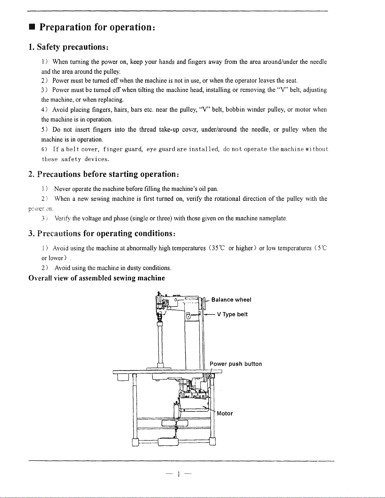
Overall view
of
assembled sewing
in
dusty conditions.
machine
35
·c
or higher) or low temperatures ( 5
Balance wheel
·c
-I-
• Cautions
1.
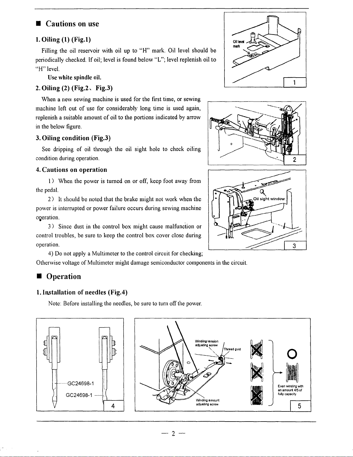
Oiling (1)
(Fig.l)
on
use
Filling the oil reservoir with oil up to
periodically checked.
"H"
level.
Use
white
2.
Oiling (2) (Fig.2, Fig.3)
When a new sewing machine is used for the first time, or sewing
machine left out
replenish a suitable amount
in the below figure.
If
oil; level is found below "L"; level replenish oil
spindle
oil.
of
use for considerably long time
of
oil to the portions indicated by arrow
"H"
mark. Oil level should
is
used again,
3. Oiling condition (Fig.3)
See dripping
condition during operation.
4.
Cautions on operation
l ) When the power is turned on or off, keep foot away from
the pedal.
2)
It should be noted that the brake might not work when the
power
is
interrupted or power failure occurs during sewing machine
OQeration.
3)
Since dust in the control box might cause malfunction or
control troubles, be sure to keep the control box cover close during
operation.
4) Do not apply a Multimeter to the control circuit for checking;
Otherwise voltage
of
oil through the oil sight hole to check oiling
of
Multimeter might damage semiconductor components in the circuit.
be
to
------
• Operation
1.
Installation
Note: Before installing the needles, be sure to turn off the power.
... ·GC24698-1
of
needles (Fig.4)
GC24698-1 -
..
4
-2-
Wnding
adjusting
amount
screw
~
Even
an
amount
fully
I
0
winding
capacity
415
wrth
of
5
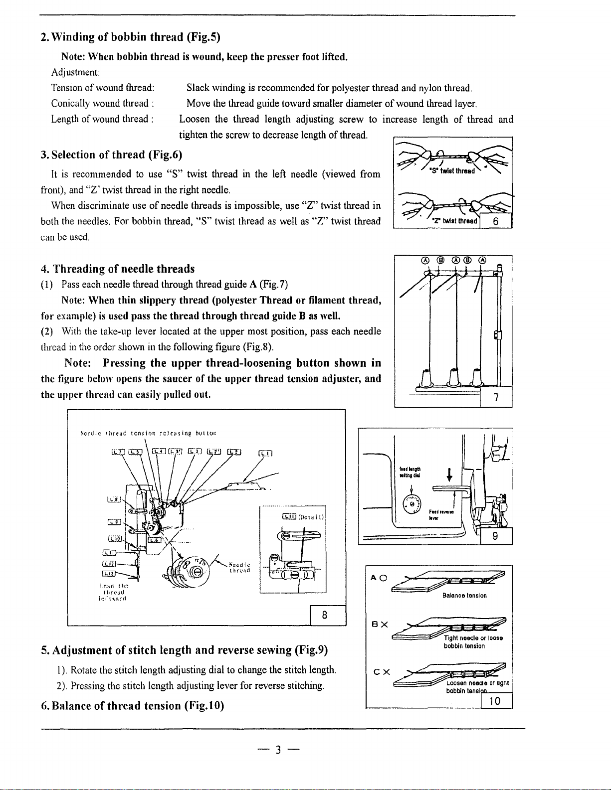
2.
Winding
of
bobbin
thread
(Fig.5)
Note: When bobbin thread
Adjustment:
Tension
Conically wound thread :
Length
3.
Selection
It
front), and
When discriminate use
both the needles. For bobbin thread,
can be used.
4.
Threading of needle threads
(1) Pass each needle thread through thread guide A (Fig.7)
of
wound thread:
of
wound thread :
of
thread (Fig.6)
is recommended to use
"Z'
twist thread
of
Note: When thin slippery thread (polyester Thread
for example)
(2) With the take-up lever located at the upper most position, pass each needle
thread
is
used pass the thread through thread guide
in
the order shown
in
Note: Pressing the
is
wound, keep the presser foot lifted.
Slack winding is recommended for polyester thread and nylon thread.
Move the thread guide toward smaller diameter
Loosen the thread length adjusting screw to increase length
tighten the screw to decrease length
"S"
twist thread in the left needle (viewed from
in
the right needle.
needle threads
the following figure (Fig.8).
upper
is
impossible, use
''S"
twist thread
as
thread-loosening button shown in
well
or
of
"Z"
twist thread in
as
"Z"
twist thread
filament
Bas
well.
thread.
thread,
the tigure below opens the saucer of the upper thread tension adjuster, and
the upper
thread can easily pulled out.
of
wound thread layer.
@@
of
thread and
@@@
7
~cedlc
thrti::IC
tension
releasing
Lr.:H\ th:-:
l
hft.'Jtl
1
e.r
t·"·j\
:·cJ
5.
Adjustment
I). Rotate the stitch length adjusting dial to change the stitch length.
2).
Pressing the stitch length adjusting lever for reverse stitching.
6.
Balance
of
thread
of
stitch length
tension (Fig.l
buttot~
and
reverse sewing (Fig.9)
0)
CiJlJ
((leta
ftodltnilfl 1
•ltingdill
'f
~
i
{)
~
te
....
r
AOc7-• &E7
Balance tension
8
BX
~
16::::-
CX,;>~
,.....-
~eaeoragm
I i
,.,;t?
TI9ht needle or loose
bobbin tension
bobbin tenslnfW''"-----l
I 1 o
-3-
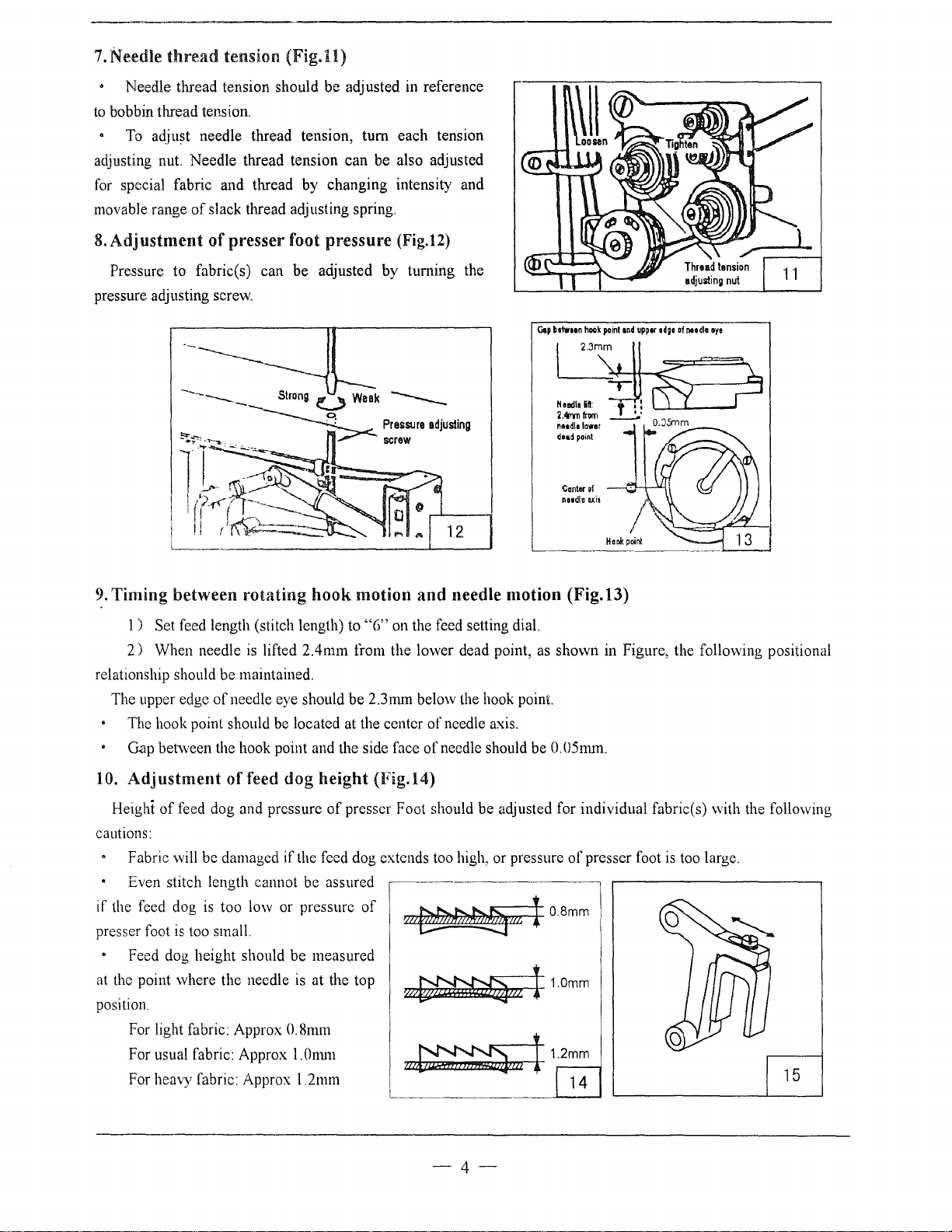
7.
Needle
to bobbin thread tension.
adjusting nut. Needle thread tension can be also adjusted
for special fabric and thread
movable range
8.
Adjustment
Pressure to fabric(s) can be adjusted by turning the
pressure adjusting screw.
thread
Needle thread tension should be adjusted in reference
To
adjust needle thread tension, turn each tension
tension
of
slack thread adjusting spring.
of
presser foot pressure (Fig.12)
(Fig.ll)
by
changing intensity and
Gop
btiwtan
naedlelcwar
d••~
point
Center
nndle
hook
of
axis
point
and
uppor
odgo
of
noodle
oye
12
]
9.
Timing between rotating hook motion and needle motion (Fig.13)
1)
Set feed length (stitch length) to "G" on the feed setting dial.
2)
When needle is lifted 2.4mm from the lower dead point, as shown in Figure, the following positional
relationship should be maintained.
of
The upper edge
The hook point should be located at the center
Gap between the hook point and the side face
10.
Adjustment of feed dog height (Fig.l4)
Height
cautions:
if the feed dog
presser foot
at the point where the needle
position.
of
feed dog and pressure
Fabric will be damaged
Even stitch length cannot be assured
is
Feed dog height should be measured
For light fabric: Approx
For usual fabric: Approx l.Onun
For heavy fabric: Approx l.2mm
needle eye should be 2.3mm below the hook point.
of
needle axis.
of
needle should be 0.05mm.
of
presser Foot should be adjusted for individual fabric(s) with the following
if
the feed dog extends too high, or pressure
I
is
too low or pressure
too small.
is
at the top
of
\
nz~m
~ml
0.8mm
I
~~~11m
of
presser foot
1 0.8mm
1.0mm
_1
~1.2_~:__.
is
too large.
15
-4-
Adjustment
1 ) Lean the machine head backward.
2)
3)
4)
height.
5) After the adjustment, tighten the feed bar setscrew.
The
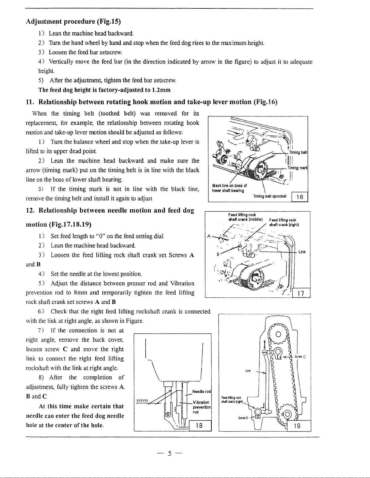
11.
Relationship between rotating hook motion
procedure
Turn the hand wheel by hand and stop when the feed dog rises
Loosen the feed
Vertically move the feed
feed dog height is
(Fig.15)
bar
setscrew.
bar
factory-adjusted
(in the direction indicated by arrow in the figure)
to
1.2mm
and
take-up lever
to
the maximum height.
motion
to
adjust it
(Fig.16)
to
adequate
When the timing
replacement, for example, the relationship between rotating hook
motion and take-up lever motion should be adjusted
1) Turn the balance wheel and stop when the take-up lever is
to
its
lifted
arrow (timing mark) put
line on the boss
remove the timing belt and install it again
12.
upper dead point.
2 ) Lean the machine head backward and make sure the
oflower
3)
If
the timing mark
Relationship between needle motion
belt
(toothed belt) was removed for its
as
follows:
on
the timing belt
shaft bearing.
is
not in line with the black line,
is
in line with the black
to
adjust
and
feed dog
motion (Fig.17.18.19)
1 ) Set feed length
2)
Lean the machine head backward.
3)
Loosen the feed lifting rock shaft crank set Screws A
andB
4)
Set the needle
5)
Adjust the distance between presser rod and Vibration
prevention rod
rock shaft crank set screws A and B
6)
the
with
right angle, remove the back cover,
loosen screw C and move the right
link
rockshaft with the link at right angle.
adjustment, fully tighten the screws
B
needle can
hole at the
link at right angle,
7)
to
connect the right feed lifting
8)
andC
At this
to
Check that the right feed lifting rocks haft crank
If
the connection
After the completion
time
enter
center
to
"0"
on the feed setting dial
at
the lowest position.
8mm and temporarily tighten the feed lifting
is
connected
as
shown in Figure.
is
not at
of
A.
8mm
make
certain
the
feed dog needle
of
the
hole.
that
Needle
Vibration
prevention
rod
18
Black
line
on
boss
lower
shan
-;("'
A -+I: ' - -.
-.....
,·0?-J)!=~-~
B
'
~·J l ~-
,~
of
bearing
Feed
shall
" -~ ··-
-.
Timing
filling
rock
crank
(middle)
--=.
-
:/1-
'B.lf)
~
bell
----
...---
~
sprocket
Feed
shaft
'--
.
1 6
lifting
rock
crank
(right)
.
:-\\~
\
I!
1J
L1nk
'':~;~/.~_
17
rod
F
.. d lifting
rock
shafl
crank
(nghl)
-5-
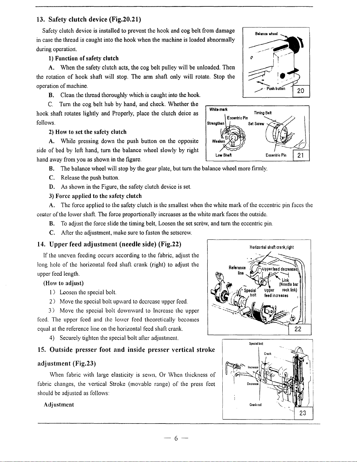
13. Safety clutch device (Fig.20.21)
Safety clutch device
in case the thread
during operatiort.
1)
Function
A. When the safety clutch acts, the cog belt pulley will be unloaded. Then
the rotation
operation
B. Clean the thread thoroughly which is caught into the hook.
C.
hook shaft rotates lightly and Properly, place the clutch deice as
follows.
2)
A.
side
of
hand away from you as shown
B.
C.
D.
3)
A. The force applied to the safety clutch
center
B.
C.
of
hook shaft will stop. The arm shaft only will rotate. Stop the
of
machine.
Tum the cog belt hub by hand, and check. Whether the
How to
bed by left hand,
Force
of
set
While pressing down the push button on the opposite
The balance wheel will stop by the gear plate, but tum the balance wheel more ftrmly.
Release the push button.
As
shown
applied to
the lower shaft. The force proportionally increases as the white mark faces the outside.
To
adjust the force slide the timing belt, Loosen the set screw, and turn the eccentric pin.
After the adjustment, make sure to fasten the setscrew.
is
installed to prevent the hook and cog belt from damage
is
caught into the hook when the machine is loaded abnormally
of
safety clutch
the
safety clutch
tum
the balance wheel slowly by right
in
the ftgure.
in
the Figure, the safety clutch device
the
safety clutch
is
the smallest when the white mark
is
set.
White
Law
mark
Shaft
~
....,__
/·Push
of
the eccentric pin faces the
14.
Upper
If the uneven feeding occurs according to the fabric, adjust the
long hole
upper feed length.
(How to
l ) Loosen the special bolt.
2)
3)
feed.
The upper feed and the lower feed theoretically becomes
equal at the reference line
4) Securely tighten the special bolt after adjustment.
15.
Outside
adjustment
When fabric with large elasticity
fabric changes, the vertical Stroke (movable range)
should be adjusted
Adjustment
feed
adjustment
of
the horizontal feed shaft crank (right) to adjust the
adjust)
Move the special bolt upward to decrease upper feed.
Move the special bolt downward to Increase the upper
on
presser
foot
(needle side) (Fig.22)
the horizontal feed shaft crank.
and
inside
presser
vertical
(Fig.23)
is
sewn, Or When thickness
of
the press feet
as
follows:
stroke
of
Horizontal
Spe~al
boll
shaft
crank,right
-
23
-6-

1 ) Loosen the special bolt.
2)
The vertical strokes
set.
3 ) The vertical strokes become minimum when the nut
4) After the adjustment,
The vertical strokes of the presser feet can be adjusted within· a range from 6mm to 2mm.
16.
Adjustment
of
the presser feet become maximum when the crank rod
is
moved downward and set.
fully
tighten the special bolt.
is
moved upward and
Screwing the pin that connects the link
the tolerance
otherwise, the stitch
17. Installation
1)
2)
3)
of
Fixed 1 to the
Fixed 3 to 1 with screws
Fixed 4
of
back sewing with the crank
between the stitches. Screwing the pin in clockwise can increase the stitch
of
back sewing will be increased.
of
Belt cover:
ann
with screws
to
3 and
ann
with screws
2 (2)
ofback
sewing (down) can adjust
..
v
(2)
3
of
forward sewing;
I
i
I
I
l
-7-
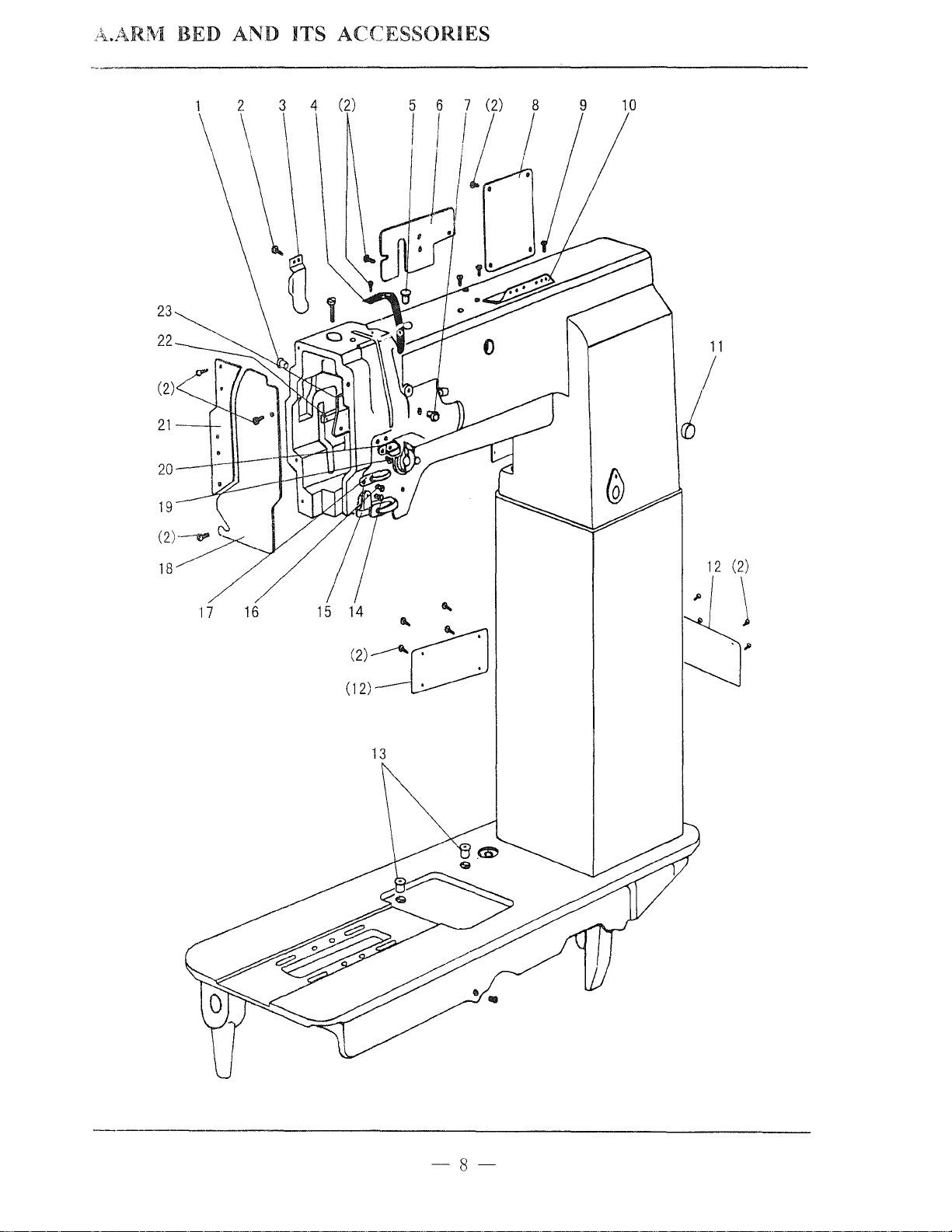
A
..
ARIVI
BED AND ITS
ACCESSORIES
1 2 3 4 (2)
\ \
\ \
. \
\
(2)
21
20
19
9
10
11
I
18
17
16
14
'
' '
(2)
------'~
(12)~
13
12
(2)
\
-8-
 Loading...