

Page 1
Purchasing
Copy
Dept
Post-Bed
HIGH
GC24628-1
Compound
Sewing Machine
LEAD
Split Needle
Bar
Feed
Lockstitch
Instruction
Manual
Parts Catalog
SHANGHAI HUIGONG
N0.3
SEWING MACHINE FACTORY
Page 2

Page 3
---
CONTENTS---
Instruction
Manual
Preparation for operation
1, Safety precautions
2,
Precautions
:L Precautions for
• Cautions
1 , Lubrication
2,
Lubrication (2)
3,
Condition
4,
Cautions
•
Or)et·atiort
I , How to attach
2,
How to
:i,
Selection
4,
How to route the
before
operating
on
use
(J)
.........................................
........................................................................
of
oil
lubrication
on
operation
...........................................................................
needle
wind
the
lower
of
Thread
upper
..............................
.....................................................................
starting
operation
conditions
.......................................................
.......................................................
·
................................
......................................................................
..............................................................
..................................................................
...................................................................
thread
...........................................................
....................................................................
thread
............................................................
·
...............................
1
1
1
1
1
1
1
l
2
2
2
2
3
:J
o,
Adjustment
fi,
Setting
7,
Threading
Balance
tL
Y,
Lower thread tens ion
I
0,
Upper thread
11, Adjustment
•1
L,
1
Timing
1:\,
AdjustmentofFeeddogheight
: '
\Valking
I.
, S
1fety
;.,~\:
.
i!.~:,l1
Parb
CaLliog
of
stitch
bobbin
of
between
clutch
<iation
il.)iJS
........................................................................
ofbobbin
thread
tension
of
pressure
rotating
foot
and
device
ofBelt
............................................................................
length
and
reverse
thread
tension
presser
cover
..............................................................
................................................................
...................................................................
..................................................................
of
presser foot
hook
motion
foot
vertiCal
...................................................................
...............................................................
sewing
and
..........................................................
stroke
...............................................
....................................................
needle motion
adjustn1ent
......................................
......................................
4
4
4
4
4
4
:'i
5
5
6
6
7
7
.\,
ARf'vl
BED
AND
ITS
ll,
THREAD
TENSl00-J
ACCESSORIES
REGULATOR
.....................................................
MECHANISM
.........................................
i-l
10
Page 4
C
ARM
SHAFT MECHANISM
D,
UPPER SHAFT & PRESSER
...........................................................
FOOT
MECHANISM
.........................................
13
15
L TAKE-UP THREAD AND SHAFT MECHANISM
F, STITCH REGULATOR MECHANISM
G,
LOWER
H,
HOOK SADDLE MECHANISM
SHAFT & FEED ROCK SHAFT MECHANISM
L OIL LUBRICATION MECHANISM
J, ACCESSORIES
......................................................................
...................................................
........................................................
.....................................................
..........................................
....................................
18
21
23
26
:JO
:53
Page 5
II
Preparation for operation:
1.
Safety precautions:
I) When turning the power on, keep your hands and fingers away from
and the area around the pulley.
2)
Power must be turned off when the machine is not in use, or when the operator leaves the seat.
3)
Power must be turned off when tilting the machine head, installing or removing the
the machine, or when replacing.
4)
Avoid placing fingers, hairs, bars etc. near the pulley,
machine is
is
in operation.
devices.
2.
Precautions before
power
3.
Precautions for
in operation.
5)
Do not insert fingers into the thread take-up cover, under/around the needle, or pulley when the machine
If
a belt cover, finger guard, eye guard are installed,
6)
starting
1)
Never operate the machine before filling the machine's oil pan.
2)
When a new sewing machine is first turned on, verify the rotational direction
on.
3) Verify the voltage and phase (single or three) with those given on the machine nameplate.
operating
operation:
conditions:
"V'
belt, bobbin winder pulley, or motor when the
do
not operate
the
area around/under the needle
the
machine without these safety
"V'
belt, adjusting
of
the pulley with the
I) Avoid using the machine at abnormally high temperatures (
lower) .
2)
Avoid using the machine in dusty conditions.
II
Cautions on use:
1.
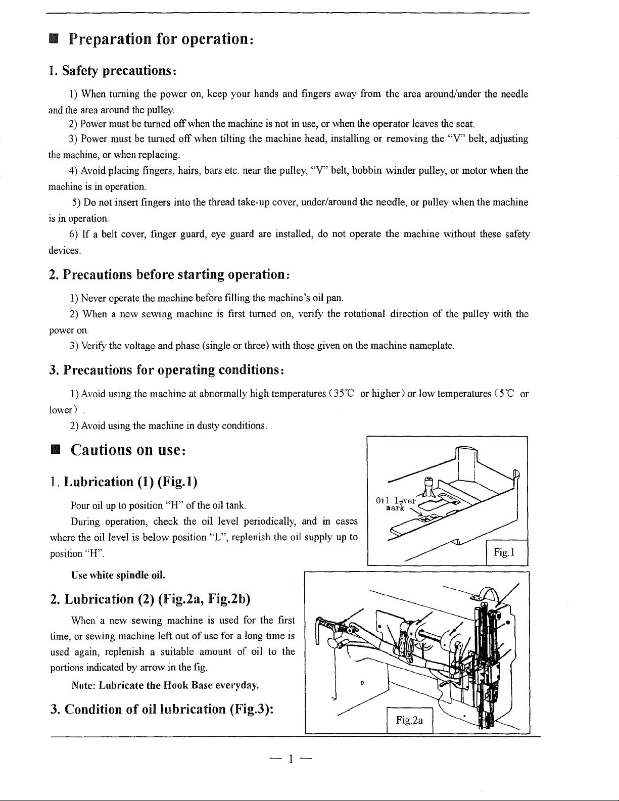
Lubrication (1)
Pour oil
During operation, check the oil level periodically, and in cases
where the oil level is below position
position
Use
2.
Lubrication (2) (Fig.2a, Fig.2b)
When a new sewing machine
time, or sewing machine left out
used again, replenish a suitable amount
portions indicated
Note:
up
to position
"H".
white spindle oil.
by
Lubricate
(Fig.l)
"H"
arrow in the
the
Hook
of
the oil tank.
"L", replenish the oil supply up to
is
used for the first
of
use for a long time
of
oil to the
fig.
Base everyday.
is
35
·c
or
higher)
or low temperatures ( 5
·c
or
3.
Condition
of
oil lubrication (Fig.3):
-I-
Page 6
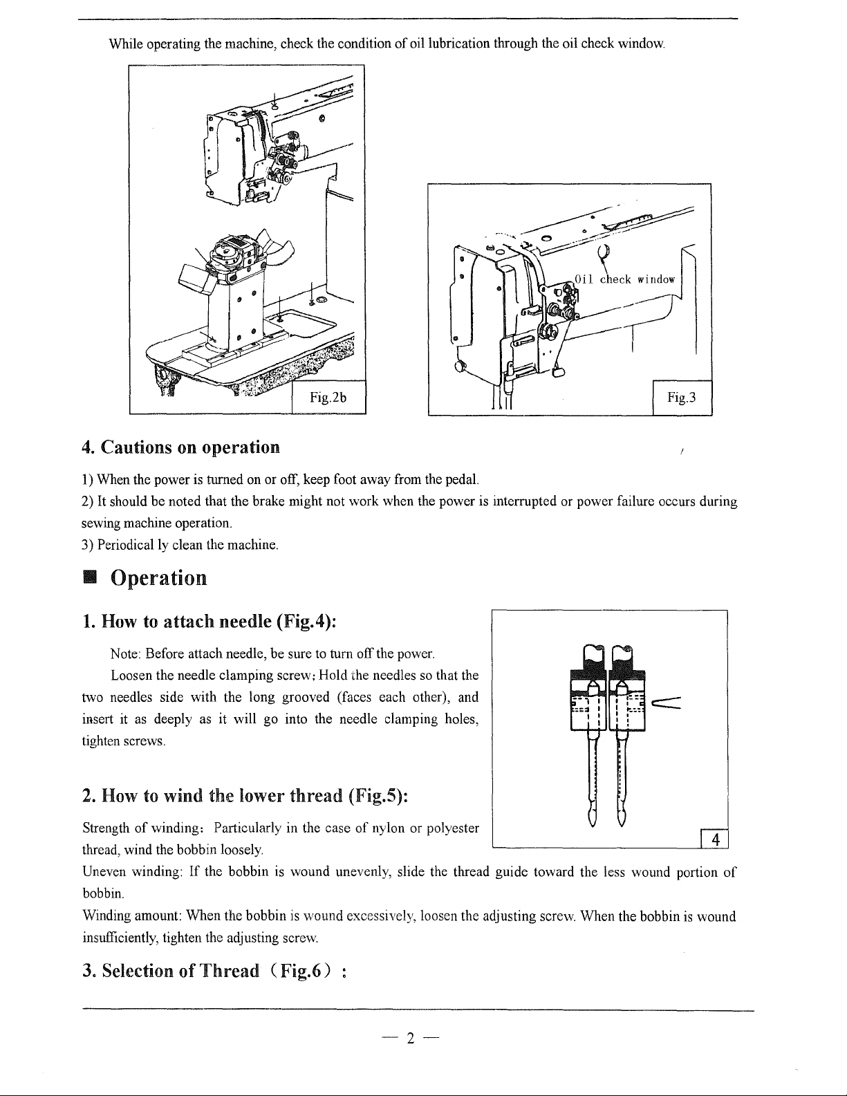
While operating the machine, check the condition
of
oil lubrication through the oil check window.
4.
Cautions on operation
1) When the power is turned on or off, keep foot away from the pedal.
2)
It
should be noted that the brake might not work when the power is interrupted or power failure occurs during
sewing machine operation.
3) Periodically clean the machine.
• Operation
1.
How
two needles side with the long grooved (faces each other), and
insert it as deeply as it will go into the needle clamping holes,
tighten screws.
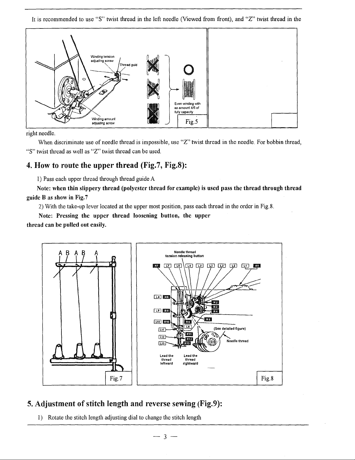
2.
How to wind the lower
Strength
thread, wind the bobbin loosely.
Uneven winding:
bobbin.
Winding amount: When the bobbin
insufficiently, tighten the adjusting screw.
to
attach
Note: Before attach needle, be sure to turn off the power.
Loosen the needle clamping screw; Hold the needles
of
winding: Particularly in the case
needle (Fig.4):
so
thread
If
the bobbin is wound unevenly, slide the thread guide toward the less wound portion
is
wound excessively, loosen the adjusting screw. When the bobbin
(Fig.S):
of
nylon or polyester
that the
is
wound
4
of
3.
Selection of
Thread
( Fig.6)
-2-
Page 7
It is recommended to use
"S"
twist thread in the left needle (Viewed from front), and
0
Even
winding
an
fully
V\linding
amount
adjusting
screw
right needle.
When discriminate use
"S"
twist thread
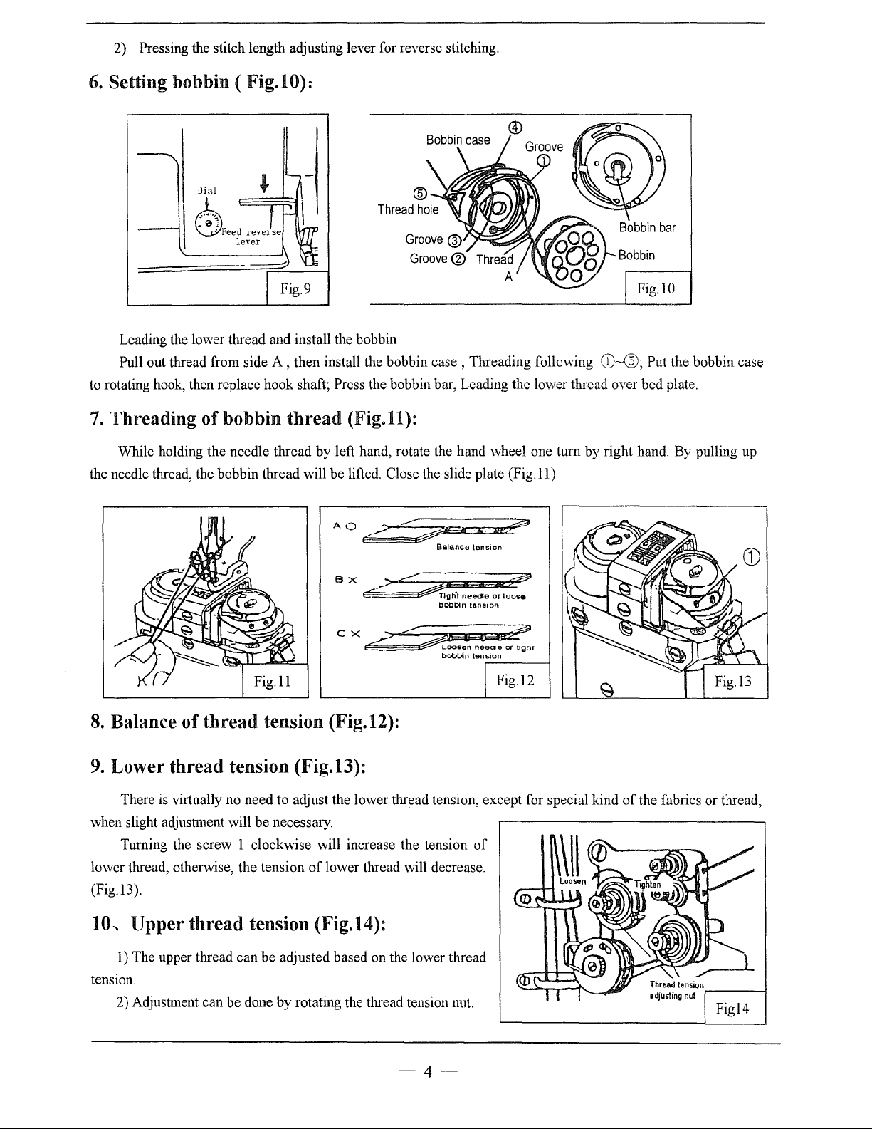
4.
How
1)
Pass each upper thread through thread guide A
Note: when
as
to
route the
thin
well
of
as
"Z"
upper
slippery
needle thread is impossible, use
twist thread can be used.
thread (Fig.7, Fig.8):
thread
(polyester
thread
for example) is used
guide B as show in Fig. 7
2) With the take-up lever located at the upper most position, pass each thread in the order in Fig.8.
Note: Pressing
thread
can
be
pulled out easily.
the
upper
thread
loosening
button,
with
amount
4/5 of
capacrty
Fig.5
"Z"
twist thread in the needle. For bobbin thread,
pass
the
thread
the
upper
"Z"
twist thread in the
through
thread
5.
Adjustment
1)
Rotate the stitch length adjusting dial
A B A B A
of
stitch length and reverse sewing (Fig.9):
Needle thread
tension releasing button
Lead the Lead the
thread thread
leftward rightward
to
change the stitch length
Fig.8
-3-
Page 8
2) Pressing the stitch length adjusting lever for reverse stitching.
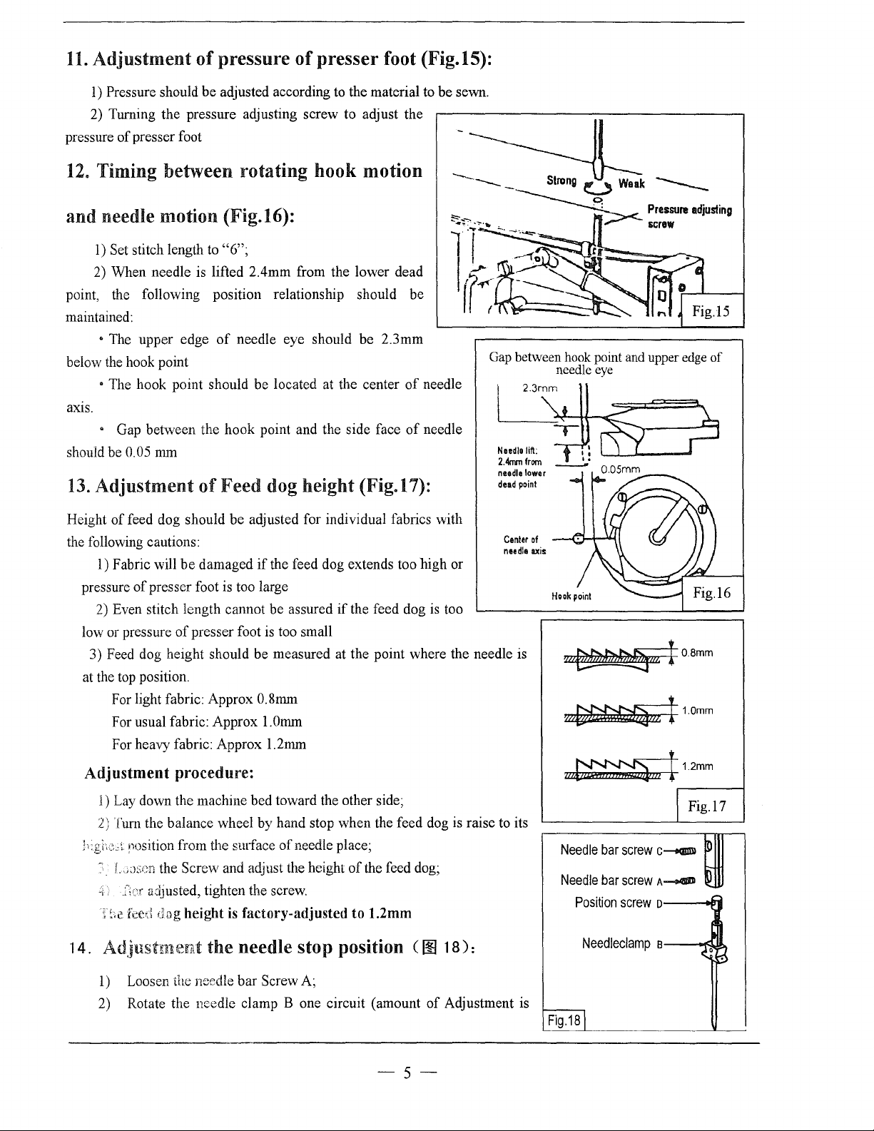
6.
Setting bobbin ( Fig.lO):
Dial
.
Feed
0
Leading the lower thread and install the bobbin
Pull out thread from side
to rotating hook, then replace hook shaft; Press the bobbin bar, Leading the lower thread over bed plate.
7.
Threading of bobbin
While holding the needle thread by left hand, rotate the hand wheel one turn by right hand. By pulling up
the needle thread, the bobbin thread will be lifted. Close the slide plate
reverse
lever
A,
then install the bobbin case , Threading following
thread
(Fig.ll):
(Fig.ll)
Fig.lO
CD--®;
Put the bobbin case
A 0
,.?
;:::;;;;.
B X
_,>:::::::~
e
ex..?'-<~
8.
Balance of
9.
Lower thread tension (Fig.13):
There is virtually no need to adjust the lower thread tension, except for special kind
when slight adjustment will be necessary.
Turning the screw 1 clockwise will increase the tension
lower thread, otherwise, the tension
(Fig.l3).
10-.
Upper
thread
thread
tension (Fig.12):
of
lower thread will decrease.
tension (Fig.14):
..--
Balance
TIOh·t
bobbin
Loo&en
bobbin
I
tens1on
1 1
needle
tan&ion
neeae
tenston
of
It?
~
or
loose
Of
ugnt
.----~
I
Fig.l2
of
the fabrics or thread,
1)
The upper thread can
tension.
2)
Adjustment can be done by rotating the thread tension nut.
be
adjusted based on the lower thread
-4-
Figl4
Page 9
11.
Adjustment
l)
Pressure should
2) Turning the pressure adjusting screw to adjust the
pressure
12.
of
presser foot
Timing between rotating hook motion
of
pressure
be
adjusted according to the material to
of
presser foot (Fig.15):
and needle motion (Fig.16):
l)
Set stitch length to
2) When needle is lifted 2.4mm from the lower dead
point, the following position relationship should
maintained:
• The upper edge
below the hook point
• The hook point should be located at the center
ax1s.
• Gap between the
0.05
should be
13.
Adjustment
mm
"6";
of
needle eye should
hook
point and the side face
of
Feed dog height (Fig.17):
be
2.3mm
be
of
of
be
needle
needle
sewn.
Gap between hook point and upper edge
1
~
··~"';'
2Ammfrom
needle
dead
needle eye
23~m~
~~
~·
lower
point
.'
0.05mm__..---
of
~
?
.......
Height
the following cautions:
of
feed dog should
1) Fabric will
pressure
low or pressure
3) Feed dog height should
at the top position.
of
2) Even stitch length cannot
For light fabric: Approx
For usual fabric: Approx l.Omm
For heavy fabric: Approx 1.2mm
be
presser foot is too large
of
be
damaged
presser foot is too small
adjusted for individual fabrics with
if
be
0.8mm
Adjustment procedure:
l)
Lay down the machine bed toward the other side;
2) Turn the balance wheel by hand stop
nosition from the smface
'
f.
.,Jscn the Screw and adjust the height
C';er
~
;,;c
a~ljusted,
feed ;Jog
tighten the screw.
height
is
factory-adjusted
Center
needle
the feed dog extends too
be
assured
measured at the point where the needle is
of
needle place;
if
the feed dog is too
when
the feed dog is raise to its
of
the feed dog;
to
1.2mm
high
or
of
axis
~I0.8mm
~ml1.0mm
Fig.l7
Needle
bar
screw
C---tGI!Ill
Needle
bar
screw
A__.
Position
screw
o
D
p
14. Adjustment the needle stop position C
l)
Loosen the needle
2) Rotate the
bar
Screw A;
needle clamp B one circuit (amount
00
18):
of
Adjustment is
-5-
Needleclamp
Fig.18l
B
g
~·
Page 10
0.6mm),
0.3mm)
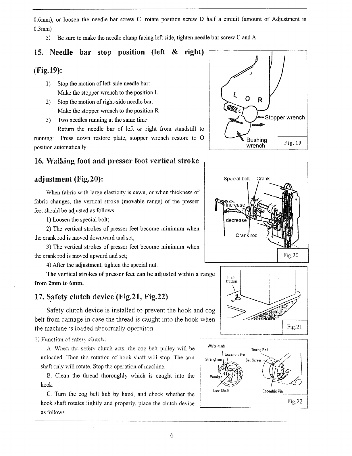
15.
or
loosen the needle
3)
Be
sure to make the needle clamp facing left side, tighten needle
Needle
bar
bar
stop position (left & right)
(Fig.19):
l)
Stop the motion ofleft-side needle bar:
Make
the stopper wrench to the position L
2)
Stop the motion
Make the stopper wrench to the position R
3) Two needles running at the same time:
Return the needle
runrung:
position automatically
16.
Press
down
Walking foot
of
right-side needle bar:
bar
of
restore plate, stopper wrench restore to 0
and
presser foot vertical stroke
screw C, rotate position screw D
left ur right from standstill to
half
a circuit (amount
bar
screw C and A
Bushing
wrench
of
Adjustment is
Fig.
19
adjustment
When fabric with large elasticity is sewn, or when thickness
fabric changes, the vertical stroke (movable range)
feet should
1)
Loosen the special bolt;
2)
The vertical strokes
the crank rod is moved downward and set;
3) The vertical strokes
the crank rod is moved upward and set;
4)
After the adjustment, tighten the special nut.
(Fig.20):
be
adjusted as follows:
of
the presser
of
presser feet become minimum
of
presser feet become minimum when
when
The vertical strokes of presser feet can be adjusted within a range
from
2mm
to
6mm.
17.
~afety
clutch device ·(Fig.21, Fig.22)
Safety clutch device is installed to prevent the hook and cog
belt from damage in case the thread is caught
the
mac.b.ine
I)
Function
A.
unloaded. Then
shaft only will rotate. Stop the operation
B.
hook.
C.
hook shaft rotates lightly
as follows.
:s
load•::d
of
safet~'
Vv'hen
Tum
th·~
Clean the thread thoroughly which is caught into the
the cog belt hub by hand, and check whether the
abnormally operati:::n.
dutch:
s2fcty
dmch
acts, the cog bell pnlley will be
th'.~
rotation
of
hook shaft
and
properly, place the clutch device
of
machine.
into the hook when
""~ll
stop. The arm
of
Special bolt Crank
Crank
Push
button
Low
Shaft
rod
Eccentric
Pin
,
..
Fig.22- J
-6-
Page 11
2)
How to
slowly
Force
3)
the lower shaft. The force proportionally increases as the mark faces the outside;
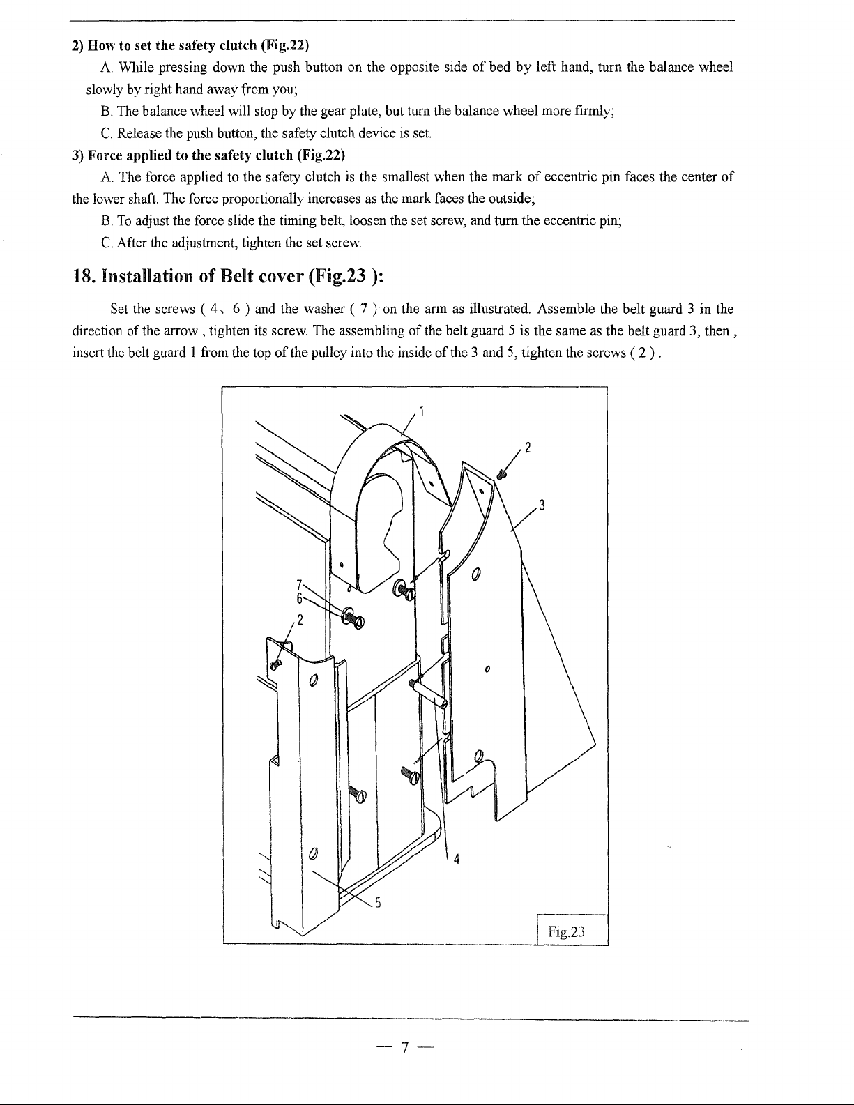
18.
set
the
safety clutch (Fig.22)
A.
While pressing down the push button on the opposite side
by
right hand away from you;
B.
The balance wheel will stop
C.
Release the push button, the safety clutch device
applied
A.
The force applied to the safety clutch
B.
To
C.
After the adjustment, tighten the set screw.
to
the
safety
adjust the force slide the timing belt, loosen the set screw, and turn the eccentric pin;
by
the gear plate, but tum the balance wheel more firmly;
clutch (Fig.22)
is
set.
is
the smallest when the
of
bed
mark
by
of
Installation of Belt cover (Fig.23 ):
left hand, turn the balance wheel
eccentric pin faces the center
of
Set the screws (
of
the
direction
insert the belt guard 1 from the top
arrow,
4,
6 ) and the washer ( 7 ) on the arm as illustrated. Assemble the belt guard 3 in the
tighten its screw. The assembling
of
the pulley into the inside
of
the belt guard 5 is the same as the belt guard 3,
of
the 3 and 5, tighten the screws ( 2 ) .
then,
--7-
Fig.23
Page 12
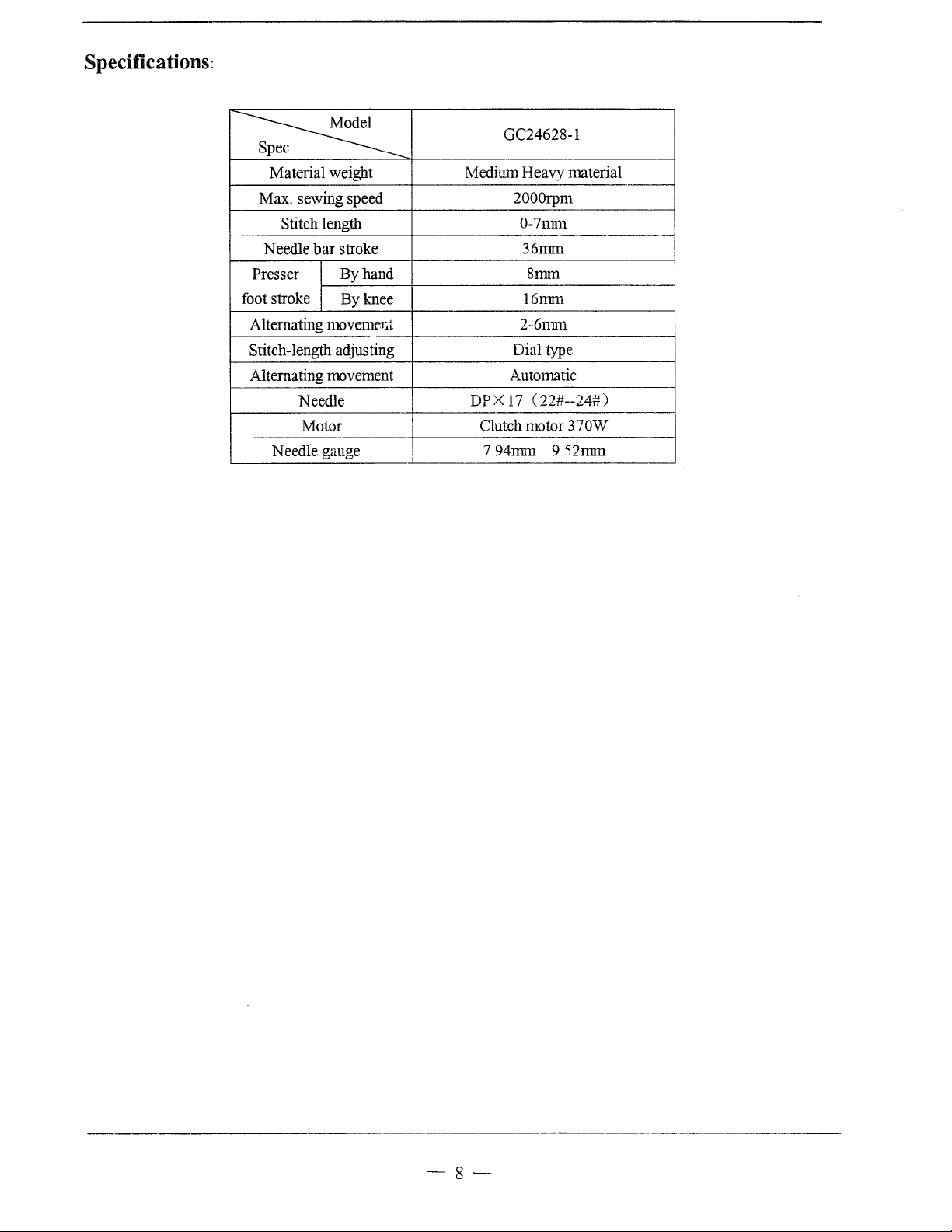
Specifications:
c
~
Material weight Medium Heavy material
Max. sewing speed
Stitch length
Needle
Presser
foot stroke
Alternating movemer..t
Stitch-length adjusting
Alternating movement
bar
stroke
By
By
Needle
Motor
Needle gauge
hand
knee
GC24628-1
2000rpm
0-7mm
·---·----"-
36mm
8mm
16mm
2-6mm
Dial type
Automatic
DPX17
Clutch motor
7.94mm 9.52mm
(22#--24#)
370W
-8-
Page 13

A.ARM
BED
AND
ITS
ACCESSORIES
2
3 4
(2)
5 6
8 9
10
19
18
(
15)
17
16
15
14
13
-9-
Page 14

A.ARM BED AND ITS ACCESSORIES
Fig.
No.
A01
HA300B2090
A02
HA300B2170
A03
H4716B8001
A04
H4717B8001
A05
H4715B8001
A06
H4718B8001
A07
H2000B2010
A08
H4719B8001
A09
HA700B2060
A10
H2400B2100
All
HA307B0673
A12
H4715H8001
A13
H4714H8001
Al4
H007013050
Al5
H2000M0090
A16
H3200B2100
A17
H3212B0066
Al8
H3000D2160
A19
H4726B8001
A20
H0213B8001
A21
H2400B2080
A22
H2400B2070
A23
H0212B8001
A24
H2400B2060
A25
H3200B2060
A26
HA7311C606
A27
H602030200
A28
HA100B2110
Part No.
Rubber plug
Screw
Oil guide plate
Thread take-up cover
Rubber plug
Arm
side cover (left)
Rubber plug
Arm
side cover (right)
Screw
Thread guide
Rubber plug
Push button
Spring
E-type ring
Cap
Screw
Thread guide
Screw
Thread guide
Face plate
Screw
Thread guide
Shaft supporter
Spacer
Oil guide plate
Screw
Pin
Screw
Description
Pes.
2
30 SM11164
1
1
1
1
1
1
SM11/64
2
1
1
1
1
1
2
1 SM9/64
1
SM9/64
1
1
1
2 SM3/16
1
1
1
1
SM 11/64( 40)x
2
2
2
SMII/64(40)x5.5
(40)
(40)
(40)
(40)
(28)
Remarks
X9
xs
x6.5
x4.5
x12.1
15
-
10-
Page 15

B.
THREAD
TENSION
REGULATOR
MECHANISM
1 2 3 4
8 9
10
11
12
13
~~;;:;.,.
14
----------------------20
----------------------21
15
16
17 18
~----23
22
24
25
26
27
28
29
48
47
46 45
44
43
42
41
40
39
38 37 36 35
34 33
-11-
32
31
30
Page 16

B.
THREAD
TENSION
REGULATOR
MECHANISM
81
49
50
51
52
54 ( 11)
5
~~
78
77
76
75
74 73 72
71
70
69 68
67
66 65 64
63 62
-12-
61
60
Page 17

B.THREAD TENSION
REGULATOR
MECHANISM
Fig.
No.
801
802
803
804
805
806
807
808
809
BlO
811
812
813
B14
815
B16
817
818
819
820
821
822
823
824
825
826
827
828
829
830
B31
332
B.?
'"
F_08
839
840
841
842
843
Part No. Description
H2504C6510
H3221B3142
H3221B6812
H4705C8001
H4706C8001
HA7311C306
H4707C8001
H007013050
H3221B6820
HA300C2030
H3221B6810
H4708C8001
H4709C8001
H:3221B0685
H3221B0683
HA112B0693
H3300B2040
HA710B0671
H3221B0682
HA106B0676
H3306B0661
HA310B0702
H4710C8001
HA115B7010
HA310B0701
HA310B0705
H3221B6816
H3221B0689
H3221B0686
H32481B721
H32481B621
H32481BC21
H32481BB21
·'
~1:;·~4818921
I
,.
..
\)
; •
~U300
•.
tL)2·1-t5 ~ GE?
H4
71
:.;c8uO
H32481BD2l
H32481B421
H32481B121
lB521
l
i~821
\
!'21
l
1
1
Screw
Tension releasing plate
Tension releasing spring
Screw
Lever
Screw
Mounting plate
E-type ring
Mounting plate
Screw
Nut
Spring
Push button
Thread tension stud
Thread tension stud
Thread tension disc
Spring
Thumb nut
Pin
Screw
Thread guide
Tension releasing disc
Spring
Thumb nut revolution stopper
Thumb nut
Thread tension disc
Pin
Thread tension stud
Thread tension stud
Thumb nut
Take-up spring guide
Screw
Stopper
Thread tension post
Screw
Bushing
Plate complete
Thread take-up spring
Plate complete
}Thread take-up spring
1
r·
: ';u'<: comp ete
Thread tension stud
Thread tension stud
1
-
Pes. Remarks
(40)
(40)
40)
(40)
(40)
(40)
(40)
(40)
(40)
(40)
(44)
(40)
(40)
x3
x5.5
x7
X8
X14
X14
x6
X23
X23
X6
X3.9
X2.9
X38.5
SM9/64
2
1
1
SM9/64
1
1
SM9/64 (
1
1
1
1
SM11/64
2
2
1
1
1
SMll/64
1
SM11/64
4
2
2
3
SM9/64
1
1
2
2
2
2
4
1
1
SM1/4
1
SM1/4
1
1
1 SM9/64
1
1
SMl/8
2
1
1
1
1
1
1
1 SM9/64
1
SMl/4
-
13-
Page 18

B.THREAD TENSION REGULATOR MECHANISM
Fig.
No.
B44
H3230K0751
B45
H3221B6817
B46
H4769E8001
B47
H3200B2100
B48
H3221B6819
B49
H3400D2030
B50
H340500663
B51
H003057050
B52
H340500661
B53
H0207C8001
B54
HE512D8001
B55
H0204C7101
B56
H3400L0050
B57
HA7311C606
B58
H3400D2060
B59
H3407D0671
B60
H3408D0681
B61
H3408D0682
B62
H3408D0686
B63
H0210C8001
B64
H007013040
B65
H3408D0684
B66
H3408D0685
B67
H3400D2100
B68
HA300C2030
B69
H0208C8001
B70
H0209C8001
B71
H3400D2110
B72
J:13210C3021
B73
H3404D0652
B74
HA7311CC06
B75
H3404D0653
lLA04D0!{;::;
B?fi
ir··
~~)
I
! . 1
....
il . .}-
'-
lLJ3
B7
,1
\1
l
87
9
IH3404D0658
B8
0
!H3404D0654
B8
1
!H3404D0651
Part
No.
Screw
Pin
Pin
Screw
Stopper
Screw
Link
Nut
Screw bar
Crank
Screw
Stop motion control lever complete
Tirread guide
Screw
Cammlation
Pin
Pin
Spring
Tension bracket
Screw
E-type ring
Lever
Pin
Spring
Screw
Plate
Cannulation
Screw
Crank
Pin
Screw
Pin
j
:lio
1~
d
'
-· J !
(.
'"- .
it;hu
.,
I,
;..:::-:p:
trif~
I
Q,
..
,.o
'',
L.JV~
'-
.-v
I
'Spring
Pin
Guide
tn'~"·r::·
;l.:!,)
,,
' •
''tiJ·'lD
Description
Pes.
1 SM11/64
1
1
SM9/64
1
1
2 SM11!64(40)x9.5
2 JKM5
2
1
1
SM11/64
1
1
1
SM11/64(40)x15
1
L=7.7
1
1
I
1
1
SM11/64(40)x22
1
1 GB/T896 4
1
I
1
2 SMI1/64(40)x8
1
L=15.2
1
SM9/64(40)x5
1
1
1
1
SM9/64
1
!
I
I
2
l
I
I
"
I
!,,'fS!l6
2
2
(40)
(40)
(32)
(40)
(28)
Remarks
x10
x6.5
X12
x6.5
x4
'---·
--
14-
I
Page 19

C.ARM
SHAFT
MECHANISM
4 5
6
7 8 9 10
14 15
17
18
19
20
-15-
Page 20

C.ARM SHAFT
MECHANISM
Fig.
No.
COl
HA307C0662
C02
H3404B0011
C03
HA105D0662
C04
HA100C2060
cos
HA100C2070
C06
H4708D8001
C07
H32111B104
cos
H32111B204
C09
H4709D8001
ClO
H3205C0661
Cli
HA113F0684
C12
H3205Cl021
Cl3
HA100F2130
C14
H3205J0662
CIS
H3205J0661
C16
HA110D0672
Cl7
H4100C2040
C18
H6304C8001
C19
HA104F0654
C20
H4713D8001
C21
H4714D8001
C22
H4716D8001
C23
H007013025
C24
H4717D8001
C2S
H4718D8001
C26
H4719D8001
C27
H4715D8001
C28
H4720D8001
C29
H4721D8001
C30
H4722D8001
C31
H4723D8001
Part No.
Set screw
Crank
Set screw
Screw
Screw
Set screw
Felt
Arm
shaft bushing (left)
Arm
shaft
Spring flange
Screw
Pulley
Screw
Bearing
Collar
Screw
Pulley
Cog belt
Screw
Link
Pin
Spring
E-type ring
Link
Pin
Link
Pin
Bushing
Screw
Pulley
Screw
Description
Pes.
1
SMl/4
1
SMl/4
1
SM9/32
1
SM9/32
1
1
SM114(24)X13
1
1
1
3
3 SM1S/64
1
1
SMlS/64
1
1
2 SM1S/64
1
1
1 SM15/64 (
1
1
1
1
1
1
1
1
1
1 SM15/64(28)x
1
2 SM15/64(28)x4.5
(40)
(40)
(28)
(28)
(28)
(28)
(28)
28) X 10
Remarks
x6
X4
x13
x14
xs.s
X14.S
X12
10.5
i
I
I
i
I
I
I
l
I
I
I
!
l
-
16-
i
I
I
!
'
Page 21

D.PRESSER
FOOT
MECHANISM
4
(2)
2 3
5 6 7 8 9 1 0
11
12
1 3
14
40
39
38
37
32
31
3029
52
18
G
59
/,
60/
61
62
-17-
Page 22

D.PRESSER
FOOT
MECHANISM
Fig.
No.
DOl
H4705E8001
D02
H4707E8001
D03
H003058060
D04
H4706E8001
DOS
H4709E8001
D06
H3115F0671
D07
H2013]0065
DOS
H2014]0066
D09
H2000J2100
DIO
H4713E8001
Dll
H20111Cl06
D12
H007009250
D13
H4714E8001
Dl4
HA307C0662
DIS
H4732E8001
DI6
H4739E8001
D17
H4734E7101
D18
H0204E8001
Dl9
H4741E8001
D20
H4742E8001
D21
H3100G2170
D22
H4730E8001
D23
H4729E8001
D24
H4727E8001
D2S
H4728E8001
D26
H3100G2130
D27
H4726E8001
D28
H4725E8001
D29
HA111G0683
D30
H4723E8001
D31
H4754E8001
D32
H4744E8001
D33
H3200E2020
D34
H4746E8001
D3S
H4768E8001
D36
H2404I0034
D37
H4748E8001
D38
H4767E8001
D39
H4752E8001
D40
H4749E8001
D41
H0207E8001
D42
H2004]0655
D43
H4717E8001
Part No. Description Pes.
Feed lifting rock shaft
Bushing
Nut
Set screw
Crank
Screw
Washer
Connecting
Screw 1 M6(0.7S)x24
Oil wick 1
Holder 1
C-type ring 1
Eccentric 1
Screw
Screw 1
Snap pin 1
Knee lifter lifting lever 1
Operation rod 1
Collar 1
Screw 1
Screw 1
Lever spring 1
Screw 1
Twist spring 1
Knee lifting lever 1
Screw
Nut
Screw 1
Screw 2 SM11164(40)xl2
Guide 1
Presser bar 1
Bushing 1
Screw 1
Spring bracket 1
Thread releasing plate 1
Screw 1
Lift lever 1
Spring
Bracket I
Screw 1
Bell crank
Screw
Roller
rod
1
2
1 (M6x0.7S)
2
1
1
1
1
2
1
1
1
I
1 SM3/16 (
1
SMl/4
(24)x7
SMl/4
(28)
SMl/4
(40)
SMI/4
(24)
SMll/64 C 40)
SMI/4
(24)
SM1S/64
SMI/4
SM1/4
SM1/8(44)x9
SM9/64
SM!l/64
(28)
(24)
(24)
(40)
(40)
28
) X
Remarks
xi6
x6
xi4
xS.S
X17
x79
x7
x19
xS.S
x8.S
10
-·-
-18-
Page 23

D.PRESSER FOOT MECHANISM
Fig.
No.
D44
H4718E8001
D45
H2004J0662
D46
H4719E8001
D47
HA100E2150
D48
H4722E8001
D49
H4721E8001
D50
H4753E8001
D51
H4708D8001
D52
HE504D8001
D52
HE304E8001
D53
HE013N8001
D54
H0205E8001
D55
H3210F0681
D56
HE510D8001
D57
HE511D8001
D58
HE106F8001
D59
HE512D8001
D60
HE507D8001
D61
H4708D8001
D62
H0206E8001
Part
No.
Description Pes. Remarks
Screw 1
Screw 1
Link
Screw
Washer
Bell crank guide
Screw
Set screw
Lifting presser 1 5/16
Lifting presser
Finger gusrd 1
Bushing 1
Screw
Bushing
Cover
Screw
Screw
Crank
Screw
Presser bar position guide
SM11/64(32)x6
SM114(40)x5
1
2 SM11/64
2
1
1 SM11/64
2 SM1/4(24)x13
1 3/8
M5x6
1
1
1
SM1/8(44)x6
2
1
1
SM1/4(24)x13
1
1
(40)
(40)
xlQ
x17.5
-19-
Page 24

E.NEEDLE
BAR
&
THREAD
TAKE-UP
LEVER
MECHANISM
35
36
37-{j
38'1}
39-{J
40----e
41-J
:~~
44~
45---r-
46----t:l
47~
48~
29
5 6 7 8
2322
10
11
12 13
65
~~~21
66
49
5o--=
:OJ
51--1
::==!
72
73
58
57
~~
54
53
52
~
\
59
60
-70
.........-71
-20-
Page 25

E.NEEDLE BAR &
THREAD
TAKE-UP
LEVER
MECHANISM
Fig.
No.
EO!
H3410C3023
E02
H3410C3022
E03
H007013070
E04
H609030220
EOS
H24211DN05
E06
H24211DM05
E07
HE033C8001
E08
HE034C8001
E09
HA110D0672
EIO
H24211D405
Ell
H24211D305
El2
H2405D0662
El3
H4716F8001
E14
H3409C0671
E15
HA100H2050
E16
H3409C0672
El7
H3410C3016
El8
H3410C3015
E19
H3410C301K
E20
HE523E8001
E21
HA7121N304
E22
H3410C301C
E23
H3410C301B
E24
H3410C3019
E25
H3410C3018
E26
H3410C3017
E27
H3204D6513
E28
H3410C3014
E29
HE505E8001
E30
H34411C410
E31
H34411C310
E32
H3410C3025
E33
HA605E0662
E34
H34412C810
E35
H34412C510
E36
H34412Cll0
E37
H34412C210
E38
H34412C310
E39
H3410Cl261
E40
H3410C1262
E41
H3410Cl265
E42
H3410C1263
E43
H3410C301I
Part No.
Description Pes. Remarks
Oil wick 1
Shaft 1
E-type ring 1 GB/T896 7
GB/T879.1 3 x22
I
1
l
1
1
SM15/64(28)x12
1
1
1
SM9/64(40)xll
4
SM9/64(40)x6.5
1
1
SM3/32(56)x4.2
1
1
SM9/64(40)x3.5
1
1
SM9/64(40)x4
2
2
M5.5x5
2
2
SM5/64(64)x6
2
SM5/64(64)x2
2
2
12
Pin
Oil wick 1
Shaft
"Thread
take-up lever
Thread take-up slide brock
Screw 1
Oil wick
Plug 1
Needle bar crank pin
Oil wick 1
Needle bar coil.Il.ecting link
Screw 1
Bushing 1
Washer
Needle bar holder 1
Screw
Guide plate 1
Screw
Screw
Needle bar supporter
Screw
Needle bar holding stopper 1
Needle bar holder 1
Felt 1
Needle bar holder 1
Needle bar rock fl·ame
Screw
Bashing for needle bar supporter 2
Bashing 1
Screw
Screw
Pin
Spring 2
Sleeve 2
Pin 2
Nut
Nut
Spring 2
Stud
Steel ball
·-·-
-21-
Page 26

E.NEEDLE BAR &
THREAD
TAKE-UP
LEVER
MECHANISM
Fig.
No.
E44
H3410C1264
E45
H34411C210
E46
H34412C410
E47
H34412C910
E48
H34412C710
E49
HE516E8001
E49
HE524E8001
E50
H32481B521
E51
H4740F8001
E52
HE505D8001
E53
H3400C2020
E54
H3200I2030
E55
H3400C2010
E56
H0206F8001
E57
H3100F2060
E58
HE506D7101
E59
H3410C301P
E60
H3406C0671
E61
H3406C0672
E62
H3400C2050
E63
H3204B0652
E64
H602040200
E65
H4736F8001
E66
H7107F8001
E67
H2012N0652
E68
H7108F8001
E69
H32311D406
E70
H7104F8001
E71
H0205F8001
E72
HE009D8001
E73
HE508D8001
E73
HE305E8001
Part No.
Description
Pes.
I
Triangle pin 2 SM5/64(64)x8
Needle bar
Spring 2
Stopper for needle clamp
Screw
Needle clamp
Needle clamp
Screw
Needle
Vibrating presser bar
Bolt
Washer
Needle bar guide
Vibrating presser bar link
Spring
Vibrating presser spring guide
Square block
Screw
Needle bar vibrating crank(left)
Washer
Bushing
Taper pin
Needle bar vibrating shaft
Nut
Screw
Screw
Oil wick
Needle bar vibrating crank(right)
Connecting link
Screw
Vibrating presser foot
Vibrating presser foot
2
2
4 SM1/8(44)x6
2
5/16
2 3/8
2
2
1
SM11164(40)x12
1
1
1
1
1
1
1
1 SM15/64(28)xJO
1
1
2
1
GB/T117
1
1
1
1
1
1
1
1
1 5/16
1 3/8
4X20
Remarks
-22-
Page 27

F.STITCH
REGULATOR
MECHANISM
2 3 4 5 6
I
I
21
8
20
27
26
(17) 25
15
~16
~17
24 23 22
-23-
Page 28

F.STITCH
REGULATOR
MECHANISM
Fig.
No.
FOl
H6309F8001
F02
HA113F0684
F03
H3200F2020
F04
H6304F8001
F05
HAIOOG2070
F06
H0204G8001
F07
H3200F2110
F08
HA100F2080
F09
H3207F0671
FlO
HA800F2020
F11
H3207F0672
F12
HA100F2110
F13
HA113F0684
F14
H4711G8001
F15
H6307F8001
F16
H3200F2050
F17
HA300C2030
F18
HA109F0673
F19
H3304F0652
F20
HA109F0671
F21
HA109F0674
F22
H3206F0662
F23
H3210F0681
F24
H3210F0683
F25
H3200F2080
F26
HA703R0067
F27
H3210F0682
F28
H3212F0692
F29
H3208G0672
F30
H3212F0691
Part No.
Description
Feed regulator 1
Screw
Screw
Link 1
Eccentric shaft
Reverse stitch shaft
Spring
Stopper pin
Reverse stitch crank
Screw
Screw
Washer
Screw
Feed reversing lever
Spring
Bracket for spring
Screw
Screw
Dial
Screw bar
0-ring
Pin
Screw
Reverse stitch shaft crank
Holding plate
Washer
Screw
Reverse bar
Square block
Guide plate
Pes.
2 SM15/64
1 SMIS/64
1
1
1
1
1
1
SM15/64
1 SM11/64
1
2
SM15/64
1
1
1
4
SMll/64 ( 40)
1 SM3!16
1
T7/lo
1
1
1
2
1
1
1
1
1
2
2
(8)
M5x6
M5xl4
(28)
(28)
(28)
(40)
(28)
(28)
xs4.3
Remarks
xfU
Xl2
xJ3.5
X8.5
X8.5
x8
x8.6
-24-
Page 29

G.LOWER
2
34
SHAFT
5 6 7 8 9
&
FEED
ROCK
SHAFT
13
14 15 17
MECHANISM
18
16
21
22
23
24
25
46 45 44 43
42
41
(39) (18)
40
(37) (36)
39
-25-
38
37
36
(18)
35
34
33
Page 30

G.LOWER SHAFT & FEED ROCK SHAFT MECHANISM
Fig.
No.
001
H6315B8001
002
H32132B204
003
H0204H8001
004
H3205H0655
005
H3205H0654
006
H6317B8001
007
H32132B204
008
H3204B0054
009
HA700F2100
010
H3208G0674
011
H32372G208
012
H32372G408
013
H32372G308
014
H3305G1011
015
H3208G2011
016
H3208G0675
017
H2405D0664
018
H3208G0676
019
H3208G0676
020
H3208G0673
021
HA105D0662
022
H3208H0662
023
H3208H0661
024
H3200H2060
025
HA7311C306
026
H6305G8001
027
H429050050
028
H3205G0662
029
H32243G205
030
HA104G0012
031
H3407C0664
032
H24211D405
033
H3407C0663
034
H2012N0652
035
H3204B0656
036
HA108G0066
037
HA105D0662
038
·
H3204G0651
039
H3204G0652
040
HA100G2120
041
HA104G0012
042
H3205G1032
043
H3204G0031
Part No.
Description
Lower shaft bushing(left)
Oil wick
Lower shaft
Feed lifting
Set screw
Lower shaft bushing(right)
Oil wick
Lower shaft bushing{middle)
Screw
Screw
Washer
Feed connecting rod
Needle bearing
Lever feed connecting cam
Link
Nut
Set screw
Screw
Screw
Connecting rod crank(middle)
Set screw
Bushing
Ball bearing
Bearing holder
Screw
Feed bar
Screw
Oil wick
Feed bar shaft
Screw
Pin
Oil wick
Connecting rod crank( right)
Screw
Feed rock shaft bushing( right)
Collar
Screw
Feed rock shaft
Felt
Feed rock shaft bushing(left)
Screw
Feed rock shaft crank(left)
Oil wick
cam
Pes.
1
1
1
1
SM1/4(40)x5
1
1
1
1
3 SM11/64
2
SMl/4
1
1
1
1
1
2
SM15/64
1
3 SM15/64
1 SM15/64
1
SMl/4
2
1
1
I
3 SM9/64 (
1
I
1
1
1
SM3/16
1
1
1
1 SM1/4
1
2
4
SMl/4
1
2
1
2
SM3/16
1
1
(40)
(24)
(28)
(28)
(28)
(40)
40)
(28)
(24)
(40)
(28)
Remarks
x7
x15
X14
X14
X14
X4
x7
X12
xl6
X4
Xl2
-26-
Page 31

G.LOWER
SHAFT & FEED
ROCK
SHAFT
MECHANISM
Fig.
No.
044
H3200G2030
045
H3200H2040
046
H2013J0065
047
H3205H0651
048
H3205H0652
049
H3205H0653
Part No.
Description
Holder
Bolt
Washer
Feed bar connecting fork
Felt
Screw
Pes.
1
1
1
1
1
1
SM1/8
(44)
Remarks
x4
-27-
Page 32

H.HOOK
16
SADDLE
MECHANISM
..1-1--11--
~_jj..-1-
~....,_1'111111
___
____
5
15
38
7
6
37
31
26
22
~.t=jj=t++H~---
---30
29
14
-28-
13
--
Page 33

H.HOOK
SADDLE lVIECHANISM
Fig.
No.
HOI
HE504J8001
H02
HE507J7101
H03
HE509J8001
H04
HE511J8001
HOS
HE512J8001
HOG
HE513J8001
H07
HE022K8001
H08
HE514]8001
H09
HE515J8001
HlO
H32142Il04
H11
HA307C0662
H12
H3204I6510
Hl3
H32142I204
H14
HA105D0662
H15
HE516J8001
H16
HE518J7101
Hl7
HE517J8001
Hl8
HE524J8001
H19
HE525J8001
H20
H005001080
l-I21
HE528J8001
H22
HE530J8001
H23
HE531J8001
l-I23
HE306I8001
H24
HE012E8001
H25
HE532J8001
H26
HE533J8001
H27
HE123I8001
H28
HE535J8001
H29
HE536J8001
H30
HE045D8001
H31
HE021B8001
H32
HE538J8001
H33
H0204I8001
H34
HE540.T8001
l-I35
HE541J8001
H36
HE542J8001
H37
HE543j8001
H38
HE544J8001
H38
HE307I8001
H39
HE545J8001
H39
HE30818001
Part No.
Hook saddle
Hook
Bobbin
Felt
Opener
Crank
Screw
Felt
Hook shaft
Gear(large)
Set screw
Set screw
Gear (small)
Set screw
Oil wick
Slide plate
Screw
Spring plate
Screw
Washer
Feed
bar
set bracket
Feed bar
Feed dog
Feed dog
Screw
Felt
Support plate
Screw
Square block
Screw
Washer
Nut
Screw
Screw
Nut
Cover plate
Hook support bracket
Screw
Plate
Plate
Needle plate
Needle plate
Description Pes.
2
2
2
2
2
2
I
2
2
2
2
2
2
2
6
2
2
24
2
4
8
1
1
1
1
1
2
2
1
1
1
1
1
4
1
1
2
2
6 SM3/16
2
2
1
1
KRT8-LPK
SMll/64
SMl/4 ( 40)
SMl/4(40)x6.5
SM1/4
SM9/64
SMS/16
GB/T97.1 8
5/16
3/8
SM11164
SMl/8
SM?/32
SMS/16
SM3/16
5/16
3/8
5/16
3/8
(32)
(40)
(40)
(20)
(32)
(44)
(32)
(20)
(32)
02)
Remarks
x9
x6
x4
xS.S
x26
x6.5
x4
x4.5
x18
x7.5
X9.5
-29-
Page 34

I.OIL
LUBRICATION
MECHANISM
363738(15)
2 3 4
39
(15)
40
41
5
42
43
44
8 9
(15)
10
11
12
35
14
15
16
17
(14)
(1)
18
19
34
-30-
Page 35

I.OIL
LUBRICATION
MECHANISM
Fig.
No.
IOl
HA300C2030
I02
H4731]8001
I03
H32175B304
I04
H4705J7101
I05
H3204K0011
I06
H411040160
I07
H4707J8001
I08
H0204K8001
I09
H0205K8001
IlO
H0206K7101
Ill
H4710J8001
!12
HA7311CC06
113
H2000M0110
!14
H3200K0190
!15
HA300B2130
!16
H3200K0200
!17
HA300B2170
!18
H3230K0751
!19
H0209K8001
120
H3215K0696
121
HllOOI2070
122
H1100I2090
123
HllOOI2110
124
H3204D6510
125
H3215K0693
126
H3215K0692
127
H3215K0694
I2X
H3215K4011
129
H3215K0695
I30
HA106B0676
I31
H32311D606
I32
H3210K0672
I33
H3200K0170
134
H3218K0072
135
H3217K0071
I36
H3200K0180
I37
H3216K0070
138
H3204K0655
139
H3200K0160
140
H3210K0674
141
H3210K0671
142
H3210K0673
142
H6204K8001
Part No. Description
Screw
Holder
Felt
Oil pipe & wick complete
Oil tank complete
Screw
Holder
Oil pipe
Oil pipe
Oil pipe complete
Spring
Screw
Holder
Holder
Screw
Holder
Screw
Set screw
Bushing
Oil pipe
Plunger
Coil spring
Guide plate
Screw
Screw
Filter
Screw
Base plate complete
Holder
Screw
Holder
Oil pipe
Holder
Oil pipe complete
Oil pipe complete
Oil wick
Oil pipe complete
Oil pipe
Holder
Holder
Oil pipe connector
Oil pipe
Oil pipe
I
Pes.
3
1
1
1
1
2
1
1
1
1
2
7
1
2
6
1
1
2
1
1
1
1
1
1
1
1
1
1
1
1
1
1
1
1
1
1
1
1
3
1
1
1
1
SMll/64
I
GB/T819.1
!
SM9/64
SMll/64
SMll/64
SMll/64
SMl/8
SM9/64
SM9/64
SM9/64
(40)
(40)
(40)
(40)
(40)
(44)
(40)
(40)
(40)
Remarks
X8
M4xl6
X6.5
xs.s
x9
xjO
x4.8
xs
x7
X6
--
-31-
Page 36

I.OIL LUBRICATION MECHANISM
Fig.
No.
143
HA100E2150
144
H3200K0250
Part No.
Screw
Holding plate
Description
Pes.
1
1
SMll/64
Remarks
(40)
XlO
-32--
Page 37

}.ACCESSORIES
28
27
26
25
®
~
~
5
21
20
19
18
17
22
16 15 14
13
12
-33-
Page 38

36~
37
34
32
33
-34-
Page 39

J.ACCESSORIES
Fig.
No.
JOl
H4740F8001
J02
HE509]8001
J03
HA300]2230
J04
H801045200
JOS
H3200L0020
J06
H3200L0030
J07
HA307J0067
J08
HA100]2120
109
HA300J2070
JlO
H3214L0067
Ill
H3214L2011
J12
H3213L0662
J13
HA104J0657
J14
HA104J0659
J15
HA104]6510
J16
HA106J0664
J17
H3213L0664
J18
H007013090
J19
HA104J0653
J20
HA104]0652
J21
H3213L0661
J22
H2400K0080
J23
HAIOOJ2180
J25
H3200L0130
J26
HA706S0067
J27
H3200L0120
J28
HA100]2140
J29
HAIOOJ2150
130
HAIOOJ2110
131
H3207L0065
J32
H6307L8001
J33
H6309L8001
J34
H6310L8001
135
H200000360
136
H0206L8001
137
H0207L8001
J38
H0208L8001
Part
No. Description
Needle
Bobbin 4
Washer
Wood
screw
Vibration preventing rubber
Vibration preventing rubber
Hinge complete
Magnet
Screw driver (larger)
Small parts 1
Knee lifter pin
Knee lifter shaft
Spring
Screw
Nut
Screw
Knee lifter crank
E-type ring 1 GB/T896 9
Washer
Screw
Oil reservoir
M-type belt
Vinyl cover
Oil tank
Bobbin winder complete
Cotton stand
Screw driver( middle) 1
Screw driver (small)
Oiler 1
Thread a needle kit 1
Belt cover (upper) 1
Belt cover (right) 1
Belt cover (left) 1
Screw 2
Washer
Screw
Screw
Pes.
1
4
4
2
2
2
1
1
1
1
1
2
SM15/64
2
SM15/64
1
1
1
1 SM5116
1
1
1
1
1
1
1
SMll/64
2
SM15/64
4
SM15/64
1
(28)
(18)
(28)
(40)
(28)
(28)
Remarks
x28
x13
XlO
x6.2
X18
xlQ
-35-
Page 40

SHANGHAI HUIGONG
N0.3
SEWING MACHINE FACTORY
ADD: 1418,
Yishan
Road, Shanghai,
China
Zip Code: 201103
Overseas
Business: TEL: 86-21-64853303 FAX: 86-21-64854304
E-mail:highlead@online.sh.cn http://www.highlead.com.cn
The
description covered in this
manual
is
subject to change for
improvement
of
the commodity without notice
2004.8.
Printed
 Loading...