

Page 1
SINGLE/DOUBLE NEEDLE POST-BED COMPOUND FEED LOCKSTITCH
SEWING MACHINE WITH ROLLER
GC24618(SINGLE NEEDLE)
GC24618-l(DOUBLE NEEDLE)
INSTRUCTION
BOOK
. ' -
•
& PARTS CATALOG
Page 2
. POST-BED COMPOUND FEED
LOCKSTITCH SEWING MACHINE WITH
INSTRUCTION BOOK
Thank
machine with roller.
This
maintain the machine correctly wbile facilitate reference
In
accept safety operation guide from professionals.
lockstitch sewing machine
be
heavy duty
high-grade leather shoes, bags, gloves and other curvy leather products.
you for choosing Single I
·
is
an
instruction book &
order
to avoid trouble, please read this instruction book carefully before operation,
1.
freely adjusted, light
with
wheel
Double
parts
needle
catalog, which will help you to use machine
.Post-bed compound feed lockstitch sewing
of
parts.
BRIEF INTRODUCTION OF MACHINE
Single needle I Double needle post-bed compound
with
roller
is
and
feed
elegant
smooth
and
in
running with
driven roller presser
in
appearance, nice and even
ball
bearing
foot,
and
and
is
especially suitable
ROLLER
and
and
feed
in
stitches which can
needle bearing, excellent for
for
sewing
2.
MAIN SPECIFICATIONS
1)
Max. Sewing Speed:
2)
Stitch Length
Presser Foot Lift:
3)
4)
Needle
5) Needle:
6)
Hook:
7) Max.Thicliness to
Lubrication:
8)
9) Motor:
3.
PRECAUTION
a.
Though each machine
machine parts
installing & using the machine,
trouble
perform run-in operation.
for
rotating,
Bar
may
Stroke:
be
no
2500
1.3-7mm.
7mm.(by hand)
14mm(by knee)
41mm
DP
Vertical Hook
beSewn:
has
been
strictly inspected
loose
or deformed after long distance transportation
you
must
check
colliding,
no
abnonnal resistance and abnormal sound before you
and
it
carefully. Examine
6mm.
Manual
370w Clutch Motor
tested before leaving
X
rpm
5,
11#
..
it
and ensure there
20##
factory,
with
jolt.
the
So
before
is
no
1
Page 3
b.
The thread guide way
regulator
must clean
c.
After
oil.
d.
If special sewing material or spec
will affect clearance, please refer to the professionals.
you
assy.
etc. is apt to accumulate dust, which would affect sewing performance.
it
regularly.
clean
of
the parts such
the
machine, please lubricate
ial
as
rotating hook, feeding wheel and thread tension
all
thread is used, or
the
relevant points with sewing-machine
you
want
to replace those parts which
So
you
'
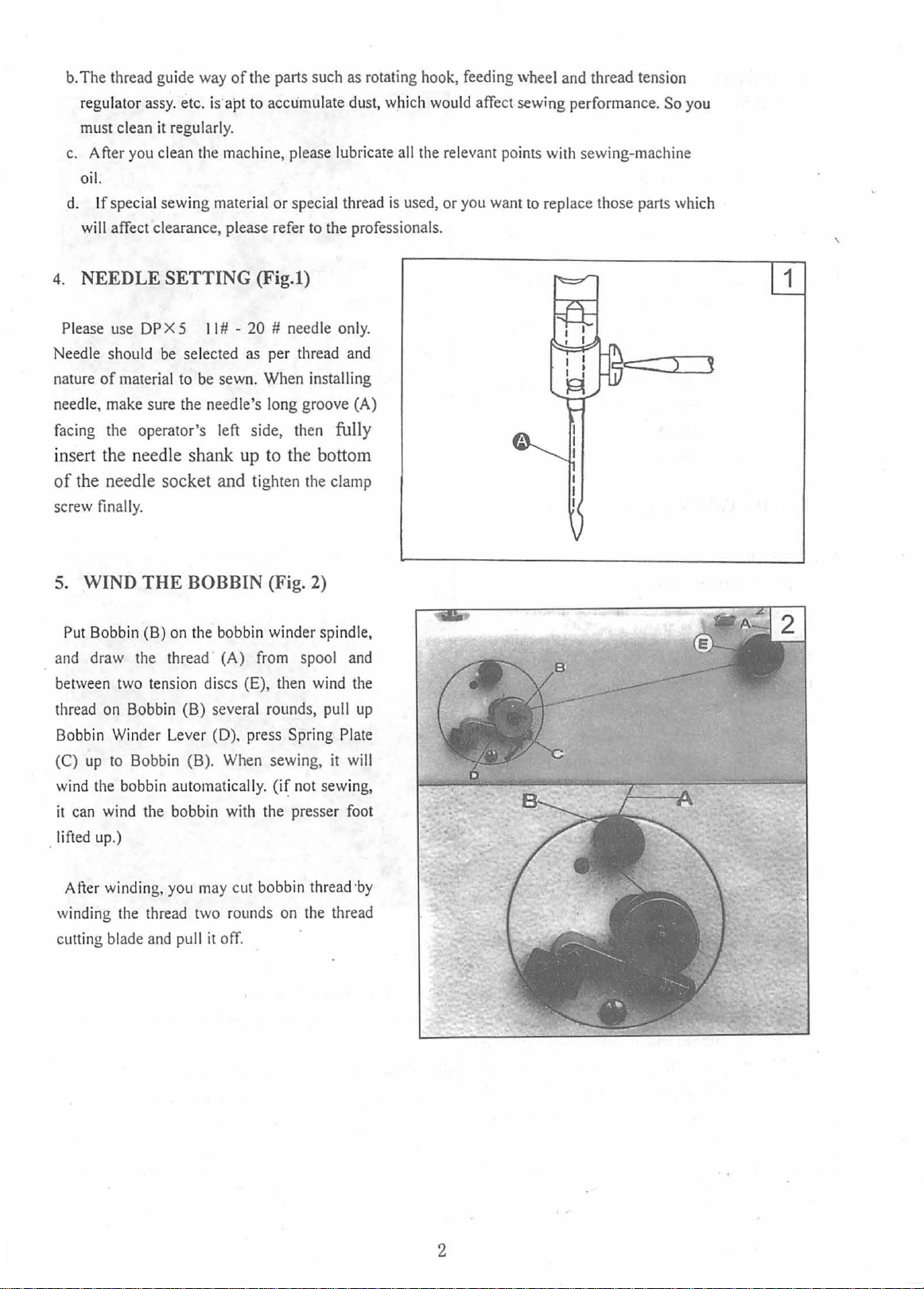
4. NEEDLE SETTING (Fig.l)
Please
Needle sho
nature of material to be sewn. When installing
needle, make
facing
insert the
of
screw
5.
and
between t
thread
Bobbin W
(C)
w
it can wind
lifted up.)
use
DP
X 5
the
II# -20
uld
be
selected
su
re the needle's long groove
the
operator's left side, then fully
needle
needle
finally.
shank
socket
and
# needle
as
per thread
up
to
tighten the clamp
WIND THE BOBBIN (Fig. 2)
Put
Bobbin (B)
draw
on
up
to
ind
the
wo
bobbin automatically. W not sewing,
on
the bobbin winder spindle,
the
thread (A)
tensi
on
discs (E), then wind
Bobbin (B) several rounds, pull
ind
er Lever (D). press Spring Plate
Bobbin (B).
the bobb
in
from
When
sewing,
with the presser
the
spool
only.
and
(A)
bottom
and
the
up
it
will
foot
1
wi
ndin
g,
you
may
After
wi
nding
the
cutting blade
thread
and
pull
cut bobbin thread
two
rounds
it
off.
on
the
·by
thread
2
Page 4
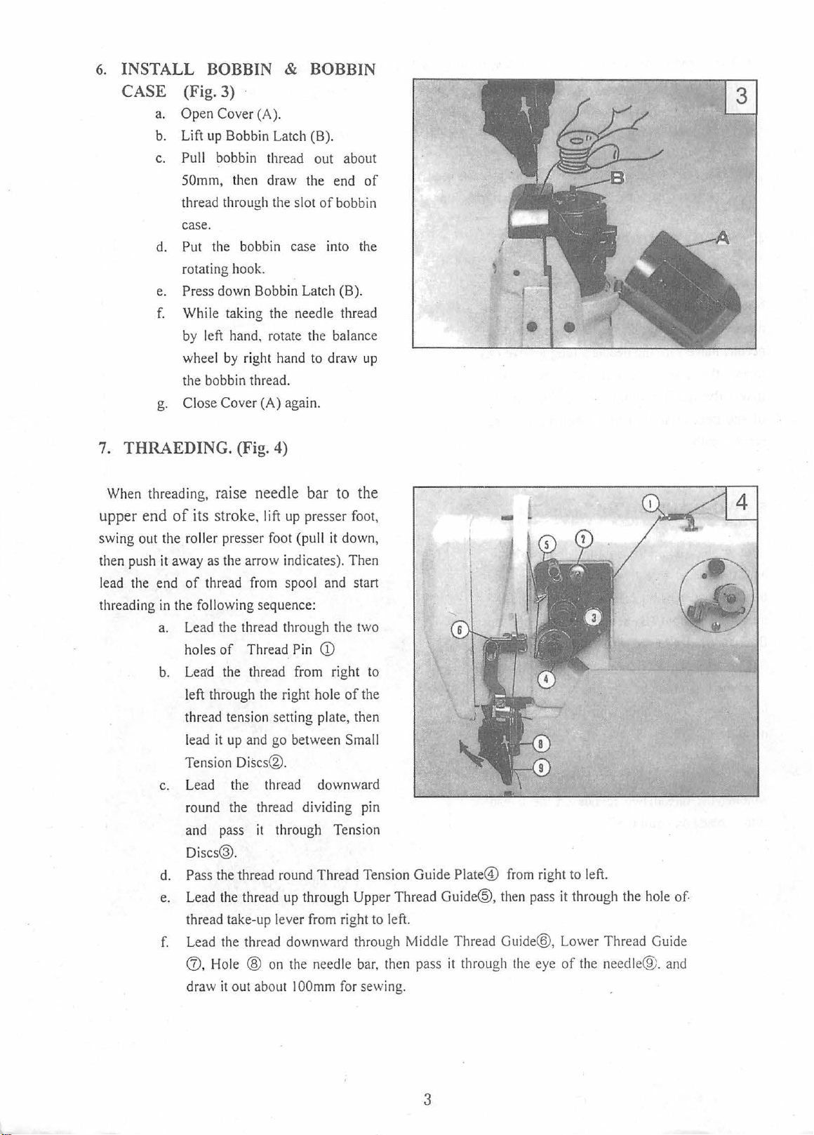
6.
INSTALL BOBBIN &
CASE
7.
THRAEDING.
(Fig. 3) ·
a.
Open Cover (A).
b. Lift
c.
d.
e. Press down Bobbin Latch (B).
f.
g.
up
Bobbin Latch (B).
Pull bobbin thre
50mm, then draw the end
thread throu
case.
Put the bobbin case into the
rotating
Whi
by
wheel
the bobbin thread.
Close Cover (A) again.
hook.
le taking the needle thread
left hand, rotate the balance
by right
(Fig. 4)
gh
ad
the slot
hand
BOBBIN
out about
of
of
bobbin
to
draw
up
When
threading, raise needle bar
upper end
swing out the
then push
lead
threading
it
away
the end
in
a.
b.
c.
d. Pass the thread round Thread Tension Guide Plate®
e. Lead the thread
f.
to
of
its
stroke. lift
roller presser foot (pu
as
the arrow indicates). Then
of
thread
the following sequence:
Lead
the thr
holes
of
Lea:d
the thread from right to
left through
thread tension setting plate, then
lead
it
up
Tension
Lead
round the thread dividing pin
and pass
Di
thread take-up l
Lead the thre
d), Hole @
draw
Discs®.
the thread downward
scs®.
it
out about I
up
presser foot,
ll
it
down,
from
spool
and
ead
through the
Thread P
and
it throu
in
CD
the
right hole
go between Small
up
eve
r from right to left.
ad
downward through Middle Thread Gui
on
the needle
OOm
of
gh Tensi
through Upper Thread Guide@,
m for sewing.
the
start
two
the
on
bar,
then pass
it
through
-
from
then
the
right
to
left.
pass
it
through the
de®,
Lower Thread Guide
eye
of
the needle® .
hole
of.
and
3
Page 5
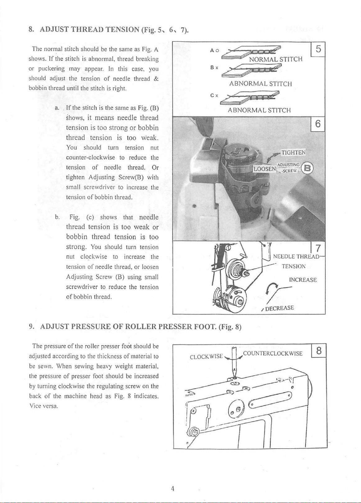
8. ADJUST
THREAD
TENSION (Fig.
5,
6,
7).
The normal stitch should
shows.
or puckeri
should adjust the tension
bobbin thread until the stitch
If
the stitch
ng
a.
. If the stitch is the same
is
abnor
may appear.
shows, it means needle thread
is
tension
too strong or bobbin
thread tension is
You
should turn tension nut
counter-clockwise to reduce the
tension
tighten Adjusti
small screwdriver to increase the
tension
b.
Fig.
th
read tension is
of
of
bobbin thread.
(c) shows that needle
bobbin thread tensi
strong.
nut clockwise to increase the
tension
Adjusting
screwdriver
of
You
of
needle thread, or loosen
Screw (B) using small
bobbin thread.
be
the same as
mal,
thread breaki
In
this case.
of
needle thread &
is
right.
needle thread. Or
ng
Screw(B)
too
should turn tension
to
reduce the tension
as
too
on
Fig.
Fig.
weak.
weak
is
you
with
too
A
ng
(B)
or
Ao/::::
Bx
Cx6,)=¢ii
•
<S~~Q;?
~~ORMAL
STITCH
~7••~
ABNORMAL STITCH
I I
,if!J
ABNORMAL STITCH
TENSION
INCREASE
r;-
/DECREASE
9. ADJUST
The pressure
adjusted according
be
sewn. When sewing heavy weight material,
the pressure
by
turning clockwise the regulating screw on the
back
of
Vice
versa.
PRESSURE
of
the roll
of
presser
the machine head
er presser
to
the thickness
foot
OF
should
as
Fig.
ROLLER PRESSER
foot
should
of
material to
be
8 indicates.
be
increased
FOOT
CLOCKWISE
. (Fig. 8)
4
Page 6
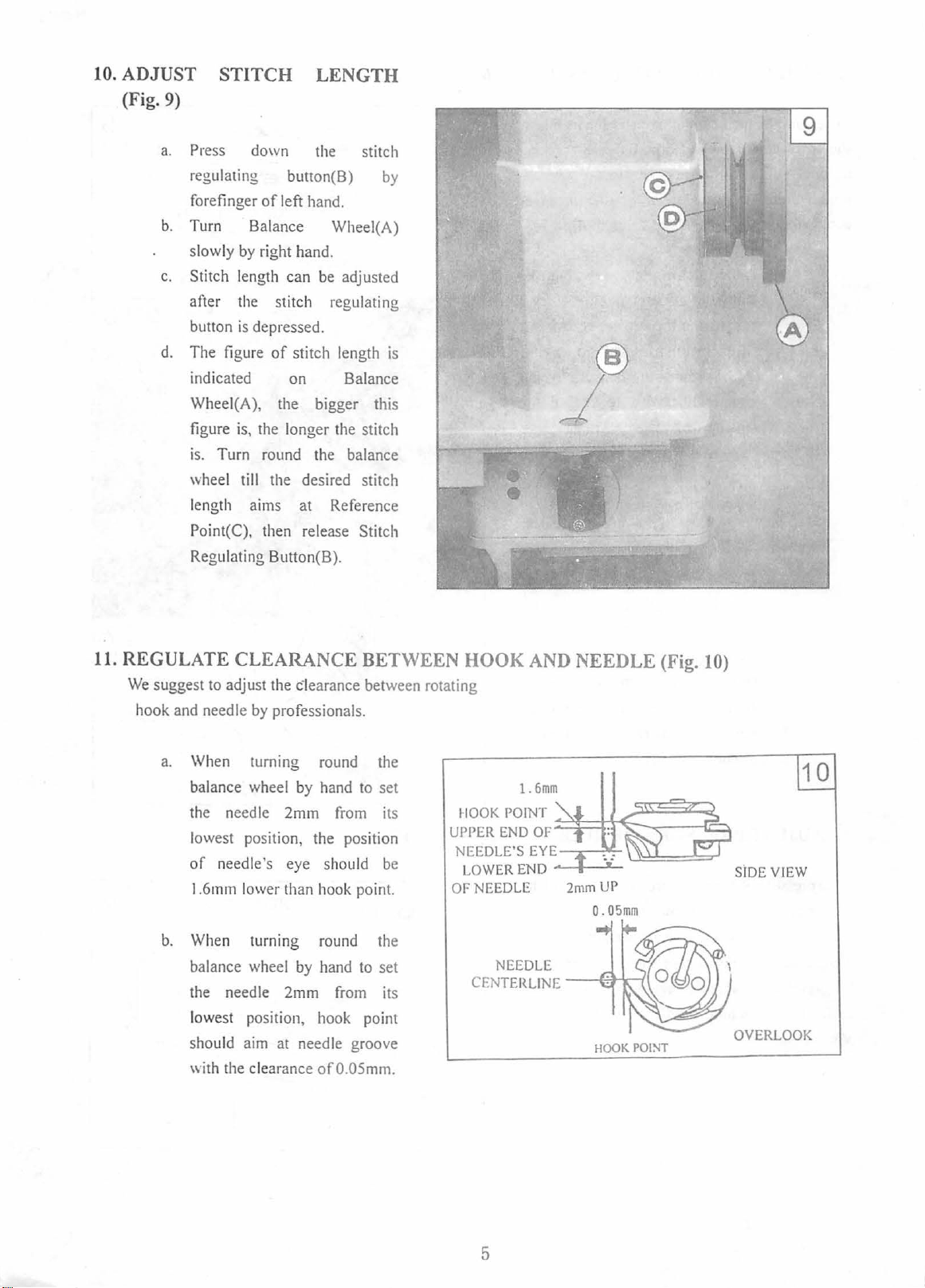
10. ADJUST STITCH LENGTH
(Fig. 9)
a.
Pre
ss down the stitch
regulating
forefinger
b.
Turn Balance Wheei(A)
slowly
c.
Stitch length can
after
button
d. The figure
indicated
Wheei(A), the bigger this
figure
is.
wheel till the desired stitch
length aims at Reference
Point(C), then release Stitch
Regulating Button(B
by
the
is
is,
Turn round the balance
bun on(
of
left hand.
right hand.
stitch regulating
depressed.
of
on Balance
the longer the stitch
B)
be
adjusted
stitch length is
).
by
®
_/
11. REGULATE CLEARANCE BETWEEN HOOK AND NEEDLE (Fig. 10)
We
suggest
hook
to
adjust the clearance between rotating
and
needle
a.
When turning round the
balance wheel
the needle 2mm
lowest position, the position
of
1.6mm
b.
When turning round the
balance wheel
the needle 2mm
lo
west position, hook point
sho
with
by
professionals.
by
hand to set
needle's eye should
lower than hook point.
by
hand
uld
aim
at
needle groove
the clearance
of0
from
to set
from
.05mm.
its
be
its
HOOK
UPPER
END
NEEDLE'S
LOWER
OF
NEEDLE
NEEDLE
CEN
TERLINE
1.6mm
POINT
~t=~~--..,..---€~
OF
EYE~.--.;JII;...
END...._....____..__
2mmUP
---<-;.t;rll
u::!=::~=-
0.05mm
HOOK
POI!'-IT
SiDE
VIEW
OVERLOOK
5
Page 7
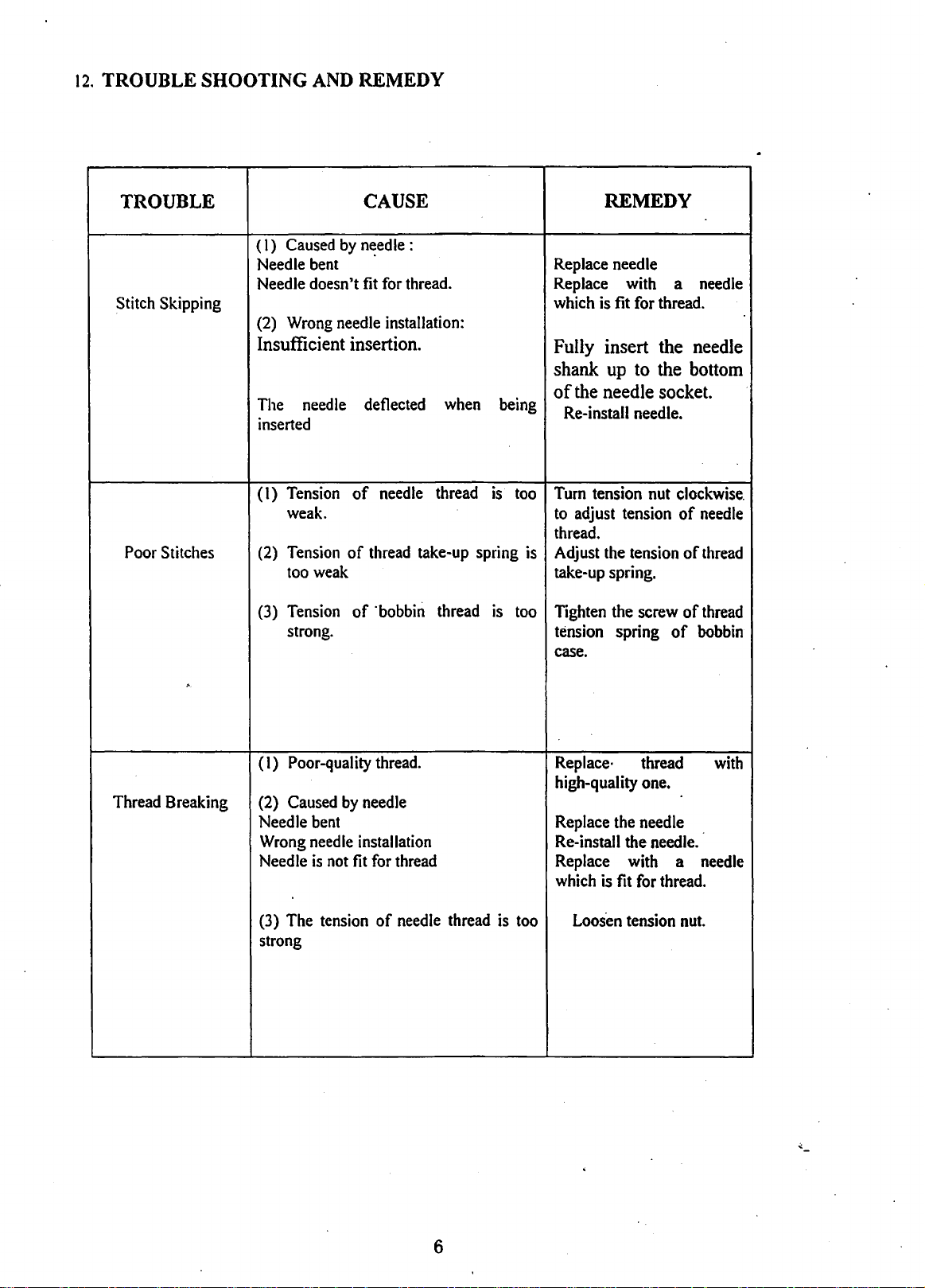
12.
TROUBLE
SHOOTING
AND REMEDY
TROUBLE
Stitch Skipping
Poor
Stitches
(
1)
Caused
Needle
Needle doesn't
(2)
Wrong
by
bent
needle
CAUSE
needle
·
fit
for
thread.
installation:
:
Replace
Replace
which
REMEDY
needle
with a
is
fit
for
thread.
needle
Insufficient insertion. Fully insert the needle
shank up to the bottom
of
The
needle
inserted
(I)
Tension
weak.
(2)
Tension
too
weak
(3)
Tension
strong. tension spring
deflected
of
needle
of
thread
of
·bobbin
when
thread
take-up spring
thread
being
is
is
too
too
the needle socket.
Re-install needle.
Turn
tension
to
adjust tension
thread.
is
Adjust
take-up spring.
Tighten
case.
the
nut
clockwise.
of
tension
the screw of
of
of
needle
thread
thread
bobbin
Thread
Breaking
(I) Poor-quality
(2)
Caused
Needle
Wrong
Needle
(3)
The
strong
by
bent
needle
is
not
tension
installation
fit
thread.
needle
for
thread
of
needle
thread
is
Replace·
high-quality
Replace
Re-install the
Replace
which
too
the
is
fit
Loos.en
thread
one.
needle
needle.
with
for
thread.
tension
a
nut.
with
needle
..:._
6
Page 8

ARE BED
AND
ITS ACCESSORIES
i
I
i
;
I
~
9
---~
I
-8
1
10-~
··~
/
11
7
Page 9

ARE BED
AND
ITS ACCESSORIES
Ref. No.
I
2
3
4
5
6
7
8
9
10
11
14
15
16
17
18
19
Part
No. Name
119687
108246
108234
168061
210210 Screw
119027
314946 Screw
119039
700335
118430
700335
119686
700335
119092
108285-1
119091
108225
Face
Screw I
Screw
Thread Take-up Cover
4 Hole Thread Guide
Arm
Screw
Thread Guide
Screw
Thread Guide
Screw
Support
Screw
Bottom
Screw
Plate
Side Cover
Leg
Pan
of
Part
Amt. Req.
Single
I I
I I
1 1
I
I
I 1
1
2
1 1
I 1
I
I
1
2
I
Double
5
Remarks
1
I
I
1
2
I
1
I
2
1
5
8
Page 10
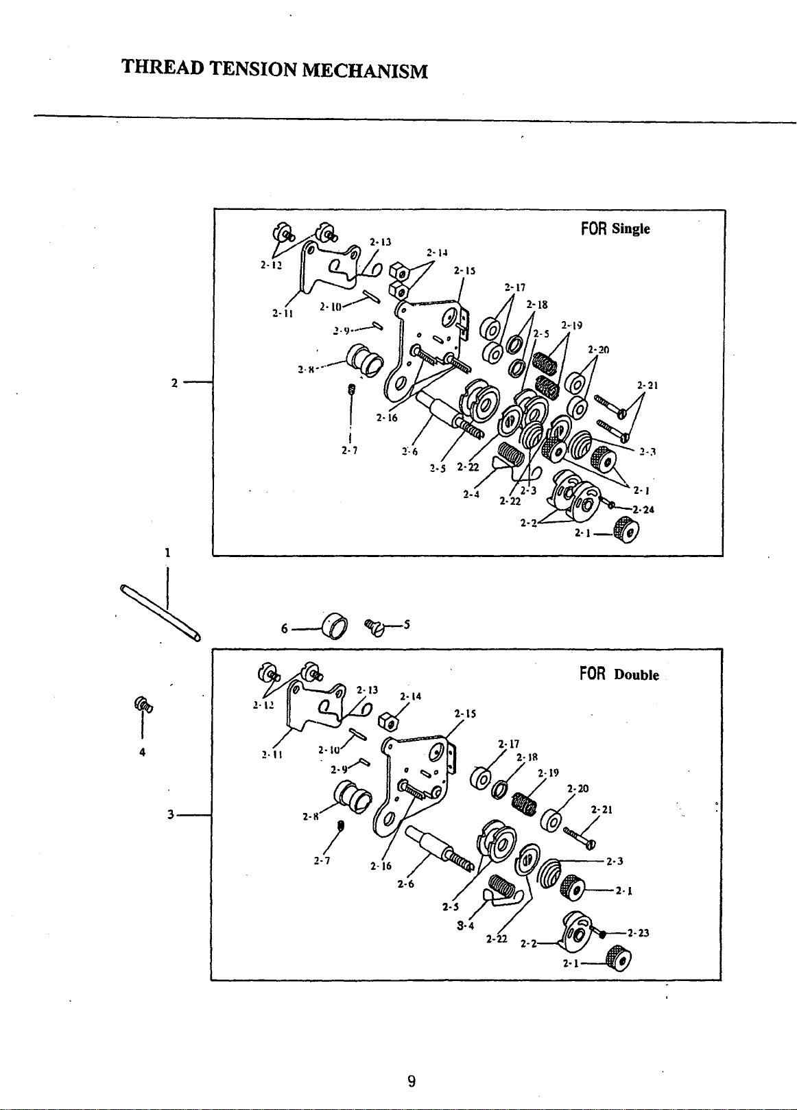
THREAD TENSION MECHANISM
z .• :
•.
~
2
1
I
2·7
2-1~
FOR
Single
1
6----0
4
3
~5
2·15
FOR
Double
9
Page 11
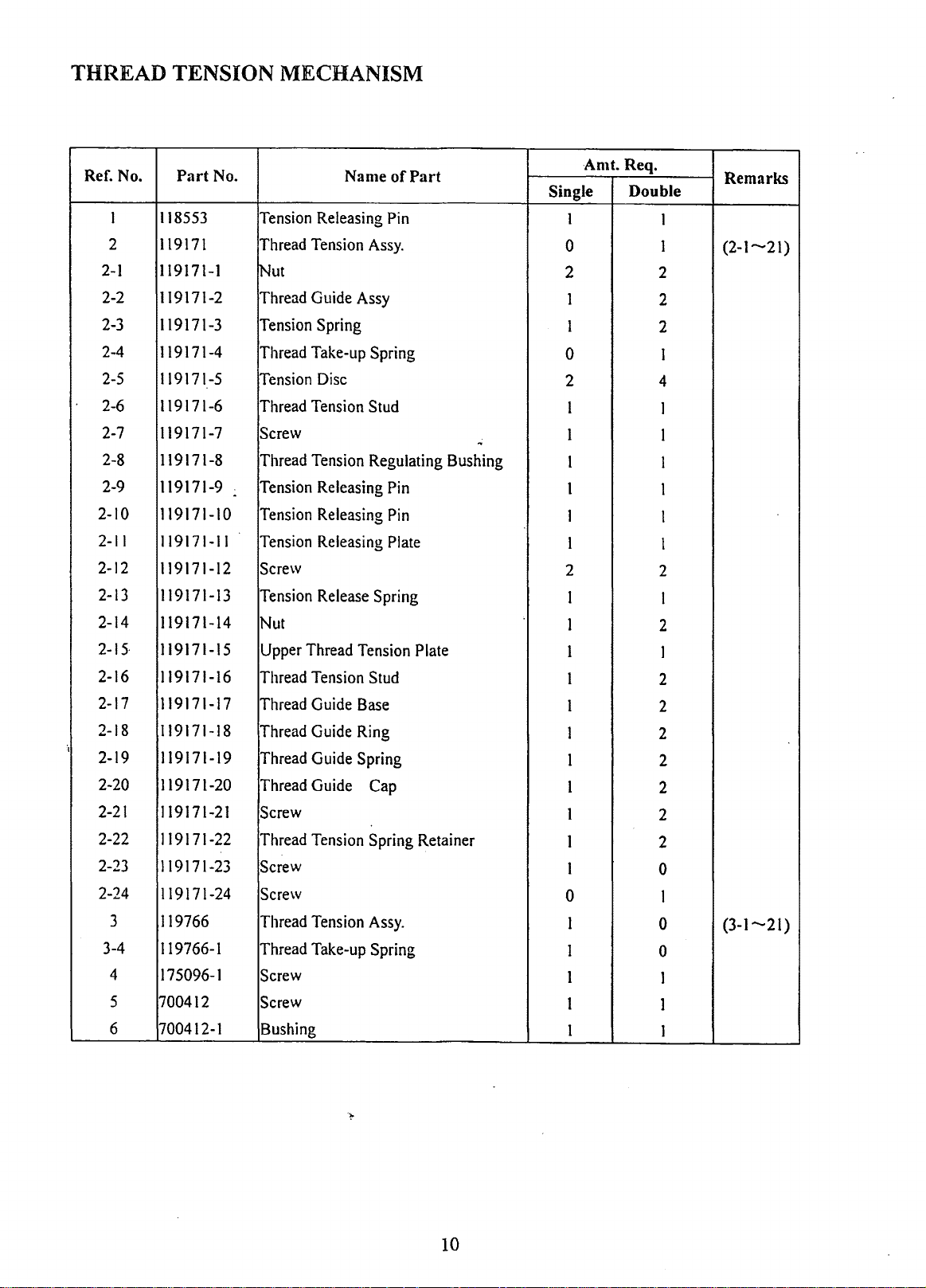
THREAD TENSION MECHANISM
·,
Ref.
2-1
2-2
2-3
2-4
2-5
2-6
2-7
2-8
2-9
2-10
2-11
2-12
2-13
2-14
2-15·
2-16
2-17
2-18
2-19
2-20
2-21
2-22
2-23
2-24
3-4
1
2
3
4
5
6
No.
Part
No.
118553
119171
119171-1
119171-2
119171-3
119171-4
119171-5
119171-6
119171-7
119171-8
119171-9
119171-10
119171-11
119171-12
119171-13
119171-14
119171-15
119171-16
119171-17
119171-18
119171-19
119171-20
119171-21
119171-22
119171-23
119171-24
119766
119766-1
175096-1
700412
700412-1
.
Tension
Thread
~ut
Thread
Tension
Thread
Tension
Thread
Screw
Thread
Tension
Tension
Tension
Screw
Tension
Nut
Upper
Thread
Thread
Thread
Thread
Thread
Screw
Thread
Screw
Screw
Thread
Thread
Screw
Screw
Bushing
Name
Releasing
Tension
Guide
Spring
Take-up
Disc
Tension
Tension
Releasing
Releasing
Releasing
Release
Thread
Tension
Guide
Guide
Guide
Guide
Tension
Tension
Take-up
of
Part
Pin
Assy.
Assy
Spring
Stud
Regulating
Pin
Pin
Plate
Spring
Tension
Plate
Stud
Base
Ring
Spring
Cap
Spring Retainer
Assy.
Spring
...
Bushing
Amt. Req.
Single
1
0
2
1
1
0
2
1
1
1
1
1
I
2
I
1
I
I
I
I
I
I
1
I
1
0
I
1
I
1
I
Double
1
1
2
2
2
1
4
1
1
1
1
I
I
2
I
2
1
2
2
2
2
2
2
2
0
I
0
0
1
I
1
Remarks
(2-1-21)
(3-1-21)
""{>
10
Page 12
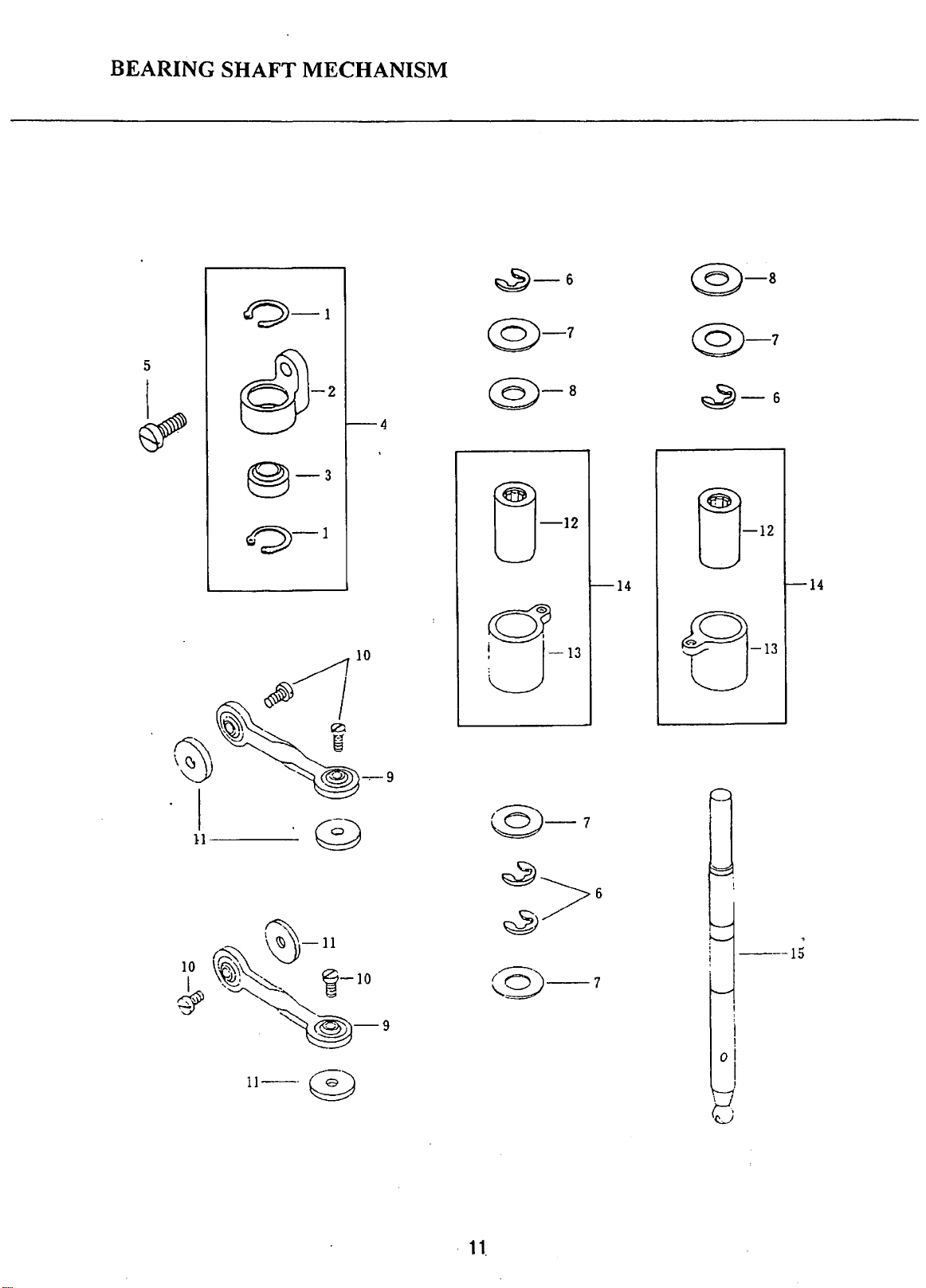
BEARING SHAFT MECHANISM
0-1
5
SJ-2
~
@3-3
o-1
f---4
~-6
@-7
@-a
u-12
;...___
14
d
o-13
@)-s
@-7
~-6
-12
u
-
14
e-13
11---
11-~
~
rg)-7
\..._
'
11.
---15
Page 13
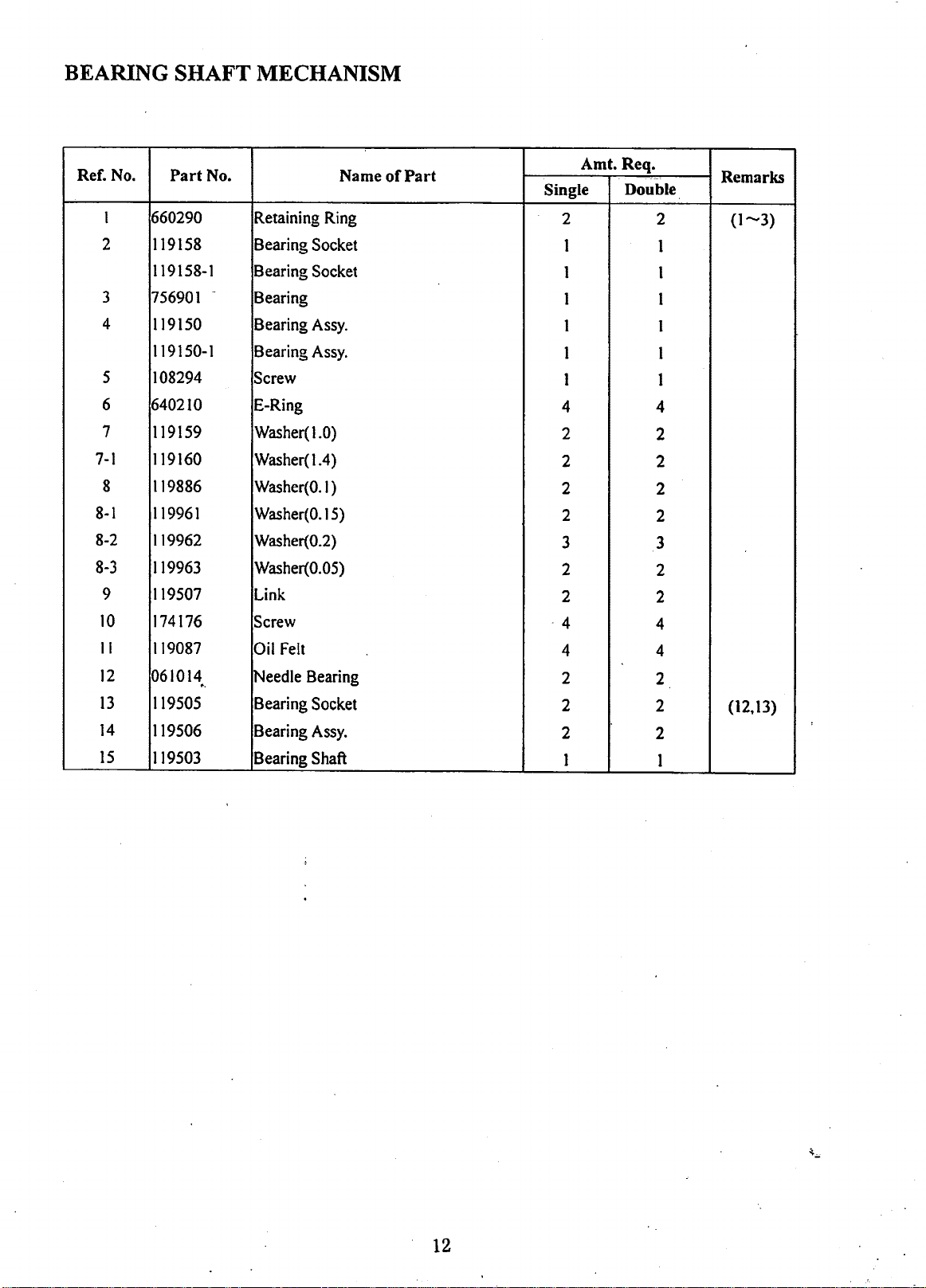
BEARING SHAFT MECHANISM
Ref.
No.
1 660290
2
3
4
5
6
7
7-1
8
8-1
8-2
8-3
9
10
II
12
13
14
15
Part
I19158
119158-1
75690I
119150
119150-1
108294
640210
119159
1I9160
119886
119961
119962
119963
119507
174176
119087
061014
..
119505
II9506
119503
No.
-
Name
Retaining
Bearing
Bearing Socket
Bearing
Bearing
Bearing
Screw
E-Ring
Washer(
Washer(1.4)
Washer(O.I)
Washer(0.15)
Washer(0.2)
Washer(O.OS)
Link
Screw
Oil
!Needle
Bearing Socket
Bearing
Bearing Shaft
Ring
Socket
Assy.
Assy.
1.0)
Felt
Bearing
Assy.
of
Part
Amt. Req.
Single
2
1
1 1
I
I
I
I
4 4
2
2
2
2
3
2
2
·4
4 4
2
2
2
1
Double
2
I
1
I
I
1
2
2
2
2
3
2
2
4
2
2
2
I
Remarks
(1-3)
(12,
13)
12
Page 14
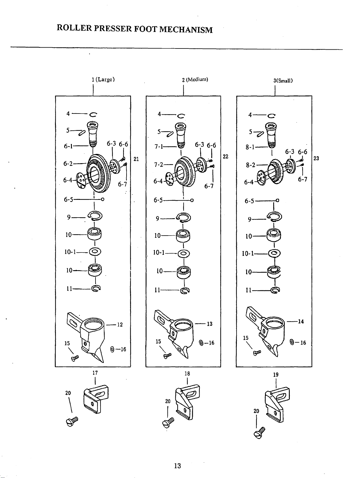
ROLLER PRESSER FOOT MECHANISM
1 (Large)
4-c
6-4
6-5
9-0
. I
Io-(9
10-1-@
. l
10-S.
11--©
1\
I
I 0
'
I
I
6-7
2 (Medium)
6-4
6-5 I 0
I
9-0
I
10-e
I
10-1-@
I
10-e
I
11--©
6-7
22
3(SmaJI)
6-5
10
9-0
I
10-e
I
11~
15
~
"
20
\
@-16
17
2
~
~-16
18
rtf
~
~
13
15
'\
~
19
20
f
~
~-16
Page 15
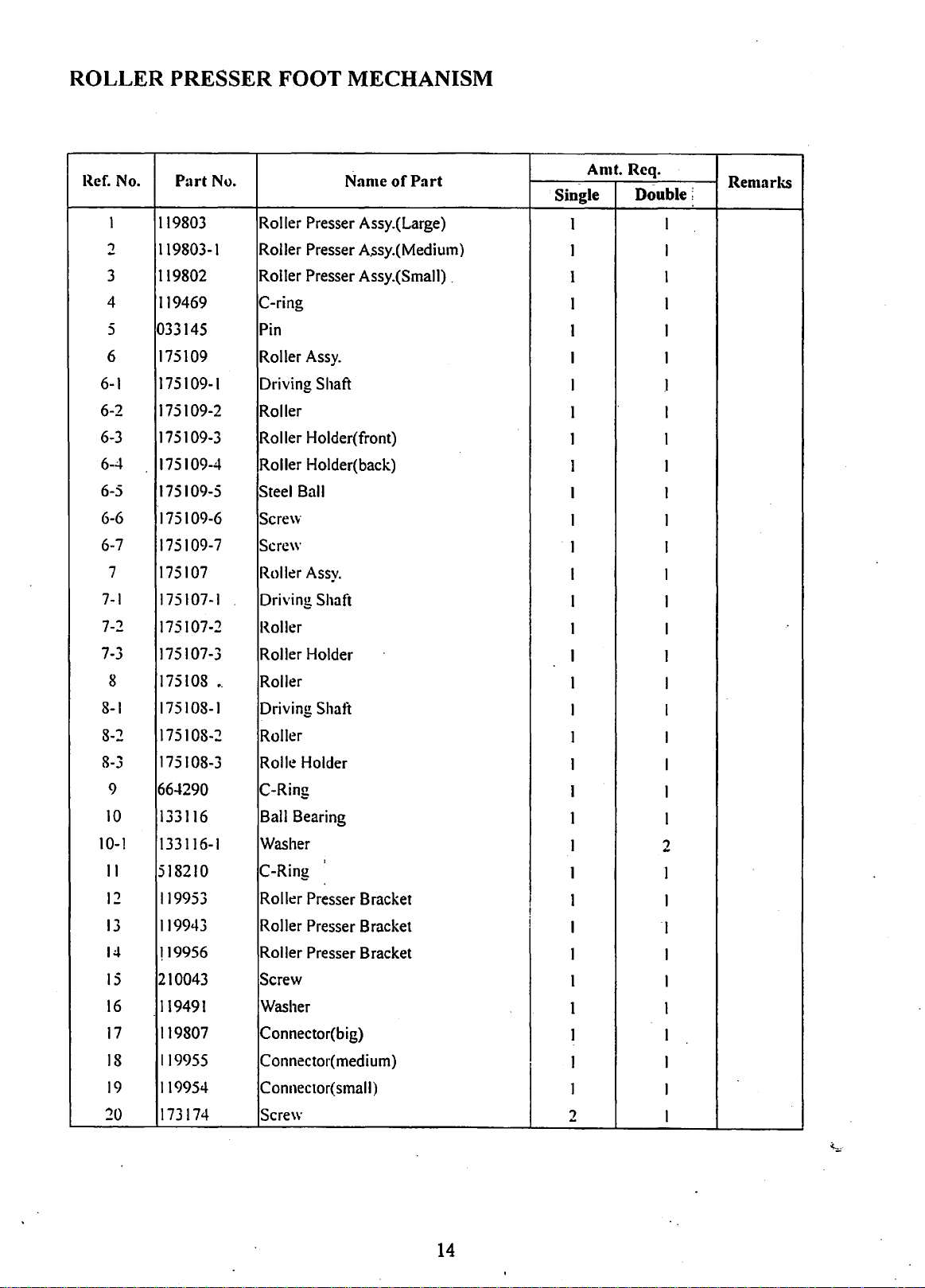
ROLLER PRESSER FOOT MECHANISM
Ref.
10-1
1
2
3
4
5
6
6-1
6-2
6-3
6-4
6-5
6-6
6-7
7
7-1
7-2
7-3
8
8-1
8-2
8-3
9
10
II
12
13
14
15
16
17
18
19
20
No.
Part
No.
119803
119803-1
119802
119469
033145
175109
175109-1
175109-2
175109-3
175109-4
175109-5
175109-6
175109-7
175107
175107-1
175107-2
175107-3
175108
175108-1
175108-2
175108-3
664290
133116
133116-1
518210
119953
119943
f19956 Roller Presser Bracket
210043
119491
119807
119955
119954
173174
Roller Presser Assy.(Large)
Roller Presser
Roller Presser Assy.(Small) .
C-ring
Pin
Roller
Assy.
Driving Shaft
Roller
Roller Holder( front)
Roller Holder(back)
Steel
Ball
Scre\v
Screw
Roller
Assy.
Driving Shaft
Roller
Roller Holder
•.
Roller
Driving Shaft
Roller
Rolle
Holder
C-Ring
Ball
Bearing
Washer
C-Ring
Roller Presser Bracket
Roller Presser Bracket
Screw
Washer
Connector(big)
Connector(
Connector( small)
Screw
Name
A.ssy.(Medium)
'
medium)
of
Part
Single
I
I I
1 I
1 I
1 I
I 1
I
1 I
1 I
1 1
I
I
1
I 1
I
I
I
1
I
1
I
I
1
1
1
1
I
i
I
I
1
1 I
1
I I
I
2
Amt. Rcq.
Double;
Remarks
I
.1
1
1
I
I
I
I
I
I
I
I
I
1
2
I
I
I
1
1
I
1
1
14
Page 16

THREAD TAKE-UP LEVER MECHANISM
-22
1
I
I
22
~~
21-~
14-~
4 3
~
~
,~~
t~a
15
14
17
1,8
6
19
~
16
0
I I
®~
15
~
I
I
20
Page 17
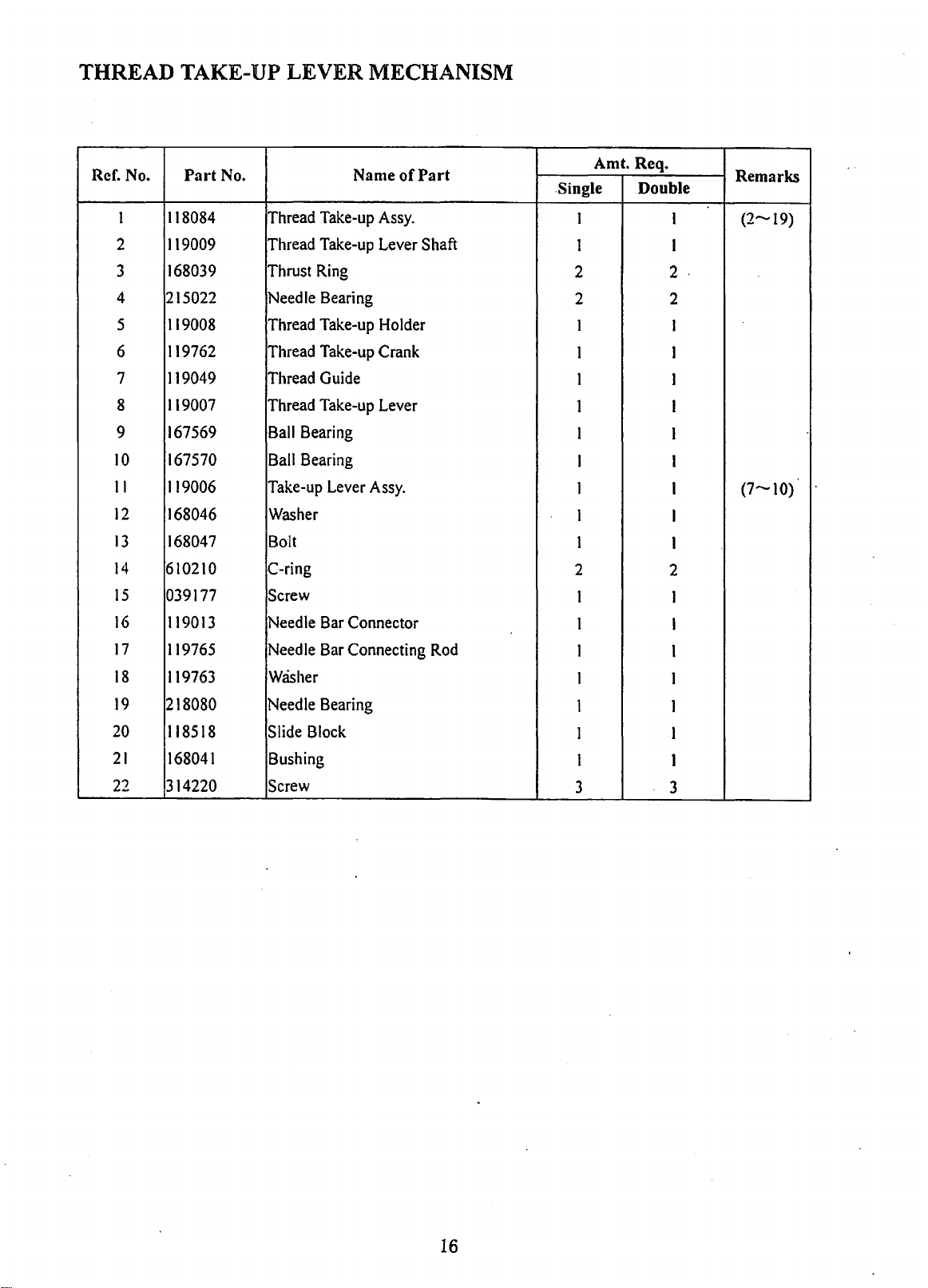
THREAD TAKE-UP LEVER MECHANISM
Ref. No.
I
2
3
4
5
6
7
8
9
10
II
12
13
14
15
16
17
18
19
20
21
22
Part
118084
119009
168039
215022
119008
119762
119049
119007
167569
167570
119006
168046
168047
610210
039177
119013
1
19765
119763
218080
118518
168041
314220
No. Name
Thread
Thread
Thrust
!Needle
Thread
Thread
Thread
Thread
Ball
Ball
Take-up
Take-up
Take-up
Ring
Bearing
Take-up
Take-up
Guide
Take-up
Bearing
Bearing
Lever
Assy.
Lever
Holder
Crank
Lever
Assy.
Washer
Bolt
C-ring
Screw
Needle
Needle
Bar
Connector
Bar
Connecting
Washer
Needle Bearing
Slide
Block
Bushing
Screw
of
Part
Shaft
Rod
Amt. Req.
.Single
1
1
2
2 2
1
I
1
1
1
I
1
1
1
2
1
1
I
I
1
I
1
3
Double
1
1
2
1
1
1
1
I
I
I
I
1
2
1
I
I
I
1
I
1
3
Remarks
(2-19)
.
(7-10)
16
Page 18

UPPER
~~
SHAFTE MECHANISM
1
2 I
I·~
i-4
7
13
I
FOR MODEL Single
16
I
~
~q
15
I
14
18
17
Page 19

UPPER
SHAFTE MECHANISM
Ref.
I
2
...
.)
4
5
6
7
8
9
10
II
I:!
13
1-t
15
16
17
18
19
No.
Part
119164
108177
119163
108225
119085
119511
118600
215124
133283
118504
118503
610370
119042-2
215028
175150
242810
119042
108225-2
130224
No.
Adapter
Screw
Connector
Screw
Washer
Upper Shaft
Bushing
Needle Bearing
Washer
Collar
Screw
C-Ring
Link
Needle Bearing
Pin
Needle
Eccentric
Screw
Screw
Name
of
B~aring
Cam
Part
Single
I
I
I
I
I
I
2
2
2
1
1
l
I
I
I
I
I
I
1
Amt. Rcq.
Double
2
2
2
0
0
0
0
0
I
I
I
I
I
I
1
I
l
l
Remarks
I
(
11)
18
Page 20

NEEDLE
BAR
1\tlECHANISM
11
10
I
~t1)
13
14
n
I i
~I
i
6
118195(2.8)
118195-1 (2.4)
118195-2(3.2)
'9
29-1=-~
~off/
.
26
31
I I
~
28
~-27
@--19
~--20
1
S~ngle
·
19
Page 21

NEEDLE BAR MECHANISM
Ref. No.
I
2
3
4
5
6
7
8
9
10
II
12
13
14
15
16
17
18
19
20
21
22
23
24
25
26
27
28
29
29-1
30
31
Part
No.
118197
118196
108174-1
700868
700868-1
118195
118195-1
118195-2
175096
174173
175096-2
175150
215028
169137
305305
024191
118612
119718
030310
119046
119525-2
119718-2
118858
108285
118857
118543
118544
Needle Bar
~eedle
Screw
Screw
Screw
Needle Holder (2.8)
Needle Holder (2.4)
!Needle
Needle Bar
Screw
Thread Guide
Pin(
short)
Needle Bearing
Washer
Screw
Nut
...
Pin(
long)
Presser Lifting Shaft
Pin
Connecting
Washer
C-ring
Fitting Plate
Screw
Spring
Crank
Pin
II8543A Crank
640150 E-Ring
020490
130224
130224-1
134356
II8545
~pring
Screw
Screw
Needle
Washer
Name
Bar Clamp
Holder (3.2)
Rod
~
Assy.
Plate
of
Part
Amt:
Req~
Single
0
0
0
Double :
0
0
0
0 1
0
1
1
1
1
2
2
2 2
2
I
1
1 I
I
I I
1 1
1 I
1
1
1
1
I
I 1
I I
·2
I 1
1
I I
Remarks
I
1
I
I
I
1
(4,5)
(4,5)
1
0
0
0
1
2
2
2
I
I
I
I
1
I
I (24,25)
")
2
I
20
Page 22

:
·::.
NEEDLEB
ARFEEDING
. 3 2 I
MECHANISM
1 2 I
1
6
3
~~
~
b~~
~·([)
8
5
I
4
11
I
22
9~:00
Ej-14
12
17
16
21
Page 23

NEEDLE BAR FEEDING MECHANISM
Ref. No.
I
2
3
4
5
6
8
9
10
II
12
13
14
15
16
17
18
19
20
21
..,..,
Part
118600
215124
133283
118610
118285-1
130224
118594
100355
119014
119015
706196
119940
119940-5
119940-4
118521
108219
118520
314286
118520-1
118503
118504
No.
...
Bushing
Needle
Washer
Crank
Screw
Screw
Guide
Screw
Bracket
Fitting
·Screw
Needle
Needle
Needle
Fitting
Screw
Bushing
Screw
Bushing
Screw
Collar
Name
Bearing
Trough
plate
Bar
Holder
Bar
Bushing(
Bar
Bushing(lower)
plate
Assy.
of
Part
upper)
Amt. Req.
;
~(pgle.
2
2
4
1
.1
I
I
2
1
,.
3
2
I
I
I
0
0
·o
0
0
I
I
Double.
0
0
0
(}
0
0
1
2
1
3
2
I
I
I
1
I
I
I
1
1
)
Remari<S
(2
1)
22
J
...
:
..
;,.
Page 24

PRESSER
BAR
MECHANISM
~
~
·~
3-1
~-1
0
11
16
I
??
@o
~
I
15
<.i-15
24-~~
20-~
IU\[-23
t5
21
~f
22
35
I
~.~
10
-9
~11
~-12
~
1
13
1.-
~
049657 3/32"
049657-1 1/16"
29
~0
l I
25
26
27
~-28
23
Page 25

PRESSER BAR MECHANISM
I
I
!
Ref.
3-1
No.
1
2
~
..)
4
5
6
7
8
9
10
II
12
13
1-l
15
16
17
IS
19
20
21
22
..,~
....
..>
2-t
..,-
-=>
26
27
28
29
30
31
"'")
J-
~~
_)..)
34
:35
Part
119019
700785
119018
119018-1
118530
700510
19019-1
I
700510-1
119165-1
119165
173174
025874
05-l876
130187
175135
700335
069079
317950
119004
118577
100331
118535
343901
118105
IJI.t286
700017
119016
049657
049657-1
108171
118542
I
18536
118536-1
118539
640150
I
18536A
,
....
,r'90"'
IJ
..>
-
No.
Name
Presser Bar Bushing(upper)
Screw
Presser
Bar
Pin
Presser
Bar
Holder
Screw
Presser Bar Bushing(lower)
Screw
Roller Presser Retainer(upper)
Roller Presser Retainer(lower)
Screw
Spring
Bracket
Screw
Cover
Plate
Screw
Foot
Presser
Lifter
Screw
Bushing
Foot
Lifter Shaft
Screw
Spring
Plate
Screw
Guide Stud
Screw
Screw
Spring
Presser
Presser
Foot
Foot
Screw
Knee
Lifter Connecting
Lifting
Lever
Pin
Bushing
E-ring
Lifting
Lever
Assy.
!l3ushing
of
Part
Rod
Amt. Req.
Single
Double :
I
I
1
I
1
.,
I
-
I
I
I
1
I
I
1
I
I
.,
-
I
I
I
I
I
I
I
I
I I
I I
I
0
0
0
I 1
I
I
I I
)
I
1
1
I
1
1 .
1
2
I
1
1
1
I
I
I
I
I
2
I
I
I
1
I
1
I
I
1
I
)
I
1
I
I
I
I
Remarks
I
I
I
(30--33)
24
Page 26

TIMING
2
BELT
DRIVING
. . MECHANISM
6
I
\)
11
8
;1
6
~~~
·
..
~·j
;~
~
I
i !
13.
...
I
10
i
t~
\
.
.:
5
I
8
I
~~~
~
:.
~··
: \ \ . i
\
\..6'
\
@
I
i
I
9
~\
r~
I .
·I,
'\~·
I
:
!
1
25
Page 27

TIMING
BELT DRIVING
MECHANISM
Ref. No.
I
2
3 018624
4
5
6
7
8
9
10
II
12
13
Part
119097
610300
119707
335902-l
335902
119121
700689
018613
119708
069161
069161-1
119706
118726
No.
Cover 2
C-ring
Ball Bearing
Timing Belt
Screw
Screw
Collar( left)
Screw
Ball Bearing 1
Timing Belt
Timing Belt 1
Timing Belt l
Shaft
Collar( right)
Name
Wheel
Wheel
of
Part
Amt. Req ..
Single
I I
2
1 1
2 2
2
1 1
4
1
1
1
Double
2·
2·
2
4
1
1
1
l
I
l
Remarl<S
I
I
I
26
Page 28

STITCH
REGULA.
TORMECHA
6
NISl\'1
~--13
7-fi
II
L
~
~~-10
9
{1-u
~-12
3
27
Page 29

STITCH REGULATOR MECHANISM
Ref.
No.
1 175038
2
I
"\
.)
4
5
6 165356
7
8 I65356-8
9 165356-5
10
II
12
13
14
14-1
14-2
14-3
14-4
14-5
14-6
14-7
14-8
14-9
14-10
14-11
14-.12
14-13
Part
No.
~onnecting
Ball
6906
175038A
215028
118612
Bearing
~onnecting
!Needle
Bearing
Pin
Stitch Adjusting Plate
165356-1
Screw
!Nut
Spring
165356-7 E-ring
165356-6 Spring
165356-2
165356-3
175029
175029-1
175029-2
175029-3
Pin
Screw
Cam
Assy.
Stitch Regulating Slide
~Stitch
Regulating Block
IStud
175029-4 Screw
175029-5
Nut
175029-6 Presser Plate
175029-7
Screw
175029-8 Screw
175029-9
175029-10
175029-11
Stud
1
E . C
·
cccntru.:
Spring
175029-12 Collar
175029-13 Screw
Name
Rod
Rod
am
of
Assy.
Part
Amt. Req.
Single
1
1
D'otible
1
1
Remarks
1 1 ( 1 ,2)
1
I
I 1
I
1
I
1
1
I
I
I
I 1
I 1
I
1
I I
I 1
1 1
I I
I I
1
1
1 1
1
1
1 I
1 I
I 1
I
I I
1
1 I
2 2
28
Page 30

FEED
MECHANISM
l
Q)
~-6
,~J
·.~ . ·~\
·~
~~·
)'J
~1---'·
!
~~-9
~-7
10
__-J--~
f~~
. ' . .
-------
,~:
- ! /
--------------
---------
i
~
-----~·
\l
-------------------
::...-------
-
17
I I I
,.L.,.
4 3
c-~r/·'
{(\
8
-----------·
'
.
Q__)·~~}
18
13
14
13
29
Page 31

FEED
1.\'IECHANISM
Ref.
1
2
3
4
5
6
7
8
9
10
II
12
13
14
15
16
17
18
No.
Part
No.
610280
119085
133283
215124
118600
119163
108225
119164
108177
119084
11860
I Bushing
119521
130224
!335902-1
It
19521-l
700689
118603
119893
C-ring
Washer
Cap
Needle
Bearing
Bushing
Connector
Screw
Connector
Screw
Feed
Rock
Crank
Screw
Screw
Crank
Screw
Bushing
Collar
Name
Shaft
of
Part
Aint. Req.
Single
1
1
6
""
.J
1
1
1
1
1
1
1
1
""
.J
2
l
3
1
I
Double
1
1
6
3
1·
I
1
1
1
1
1
1
""
.J
2
1
3
I
I
Remarks
(16)
30
Page 32

CLUTCI-1
MECHA
2
NISM
7-7
I
4
5
7·6
7
31
Page 33

CLUTCH MECHANISM
I
!
I
I
I
I
I
I
Ref.
7-10
7-11
7-12
7-13
7-14
I
2
~
.)
...
5
6
7
7-1
7-2
7-3
7--l
7-5
7-6
7-7
7-X
7-9
No.
Part
I75025
518250
119711
1750I9
341901
133I09
II908IA
7005IO
172263
013153
173261
009-lOS
1/3264
065052
640150
175023
640I30
1)13076
()09037
1)09343
175126
No.
Shaft
C-ring
Shaft( short)
Shaft Coupler(left)
Screw
Connecting Plate
Safty Clutch
Scre\v
Safty Clutch Block
Spring
Latch
Hinge Stud
Shatt Coupler(
Pin
E-ring
Stud
E-ring
Pin
\Vash~r
Spring
Set Screw
Name
Assy.
right)
of
Part
Amt. Req.
Single
I
I
I
I
1
...
1
2
I
2
I I
I I
I
.,
-
I
2
I
I
I
I
I
Double
1
I
1
I
1
4
I
2
I
2
I
2
I
2
I
I
I
I
I
Renutri<S
I
I
(7-I-7-14)
I
I
I
I
I
I
!
l
I
32
Page 34

CENTRAL
POST
BED
MECHANISM
FOR
SINGLE
17
NEEDLE
2-~
1-
0
5
11------e
~
I
·~
4
~
16
058436(2.0)
058436-1 (1.6)
~!
ll
l 2
9
II@
,,
I'
II
~~
1
~
!
~-15
I
13
J !
~~
14
I
\
\
33
I
2
Page 35

CENTRAL POST
Ref. No.
I
2
...
.>
4
5
6
7
8
9
10
II
12
13
1-t
15
16
17
P;lrt
119145
250084
119721
119144
130224
18:!451
119725
317170
168351
305174
135292
I I 9 I
21
700689
016120
305144
05S-t36
05S436-I
210168
No.
BED
l\tlECHANISM FOR SINGLE NEEDLE
Cover Plate
Screw
Post
Washer
Screw
Screw
Stud
Pin
Screw
Plug
Washer
Bolt
Collar
Screw
Ball
Bearing
Cover Plate
Needle
Needle
Screw
Platet~.O
Plate(
Name
1
1.61
of
P;1rt
Amt.
Rcq.
Single Double
4
2
2
4
4
2
2
I
I
I
I
I
I
I
1
I
I
I
I
I
0
0
0
0
0
0
0
0
0
0
0
0
0
0
0
0
0
0
Remarks
34
Page 36

ARMSH
.
AFTMECH
ANISM
7-1
~-3r-
~-fj
I .
4
9
l-5
________
-L--------------~
u---------------
~-2
12
I u
14
I
~
@)
~
•
I
13
13
15
I
I
~
ol)
G
I
13
----::r
@:]
I
8
10-·
STEEL
FIBRE
220xL
WIRE220xL
35
Page 37

ARM
SHAFT MECHANISM
Ref.
No.
I I19702-2
2
3 1I9702-3
4
5
6
7
7-1
8
9
10
I
0-1
II
12
13
14
15
16
17
18
19
20
21
22
130224
I19702-4
700510 Screw
119702-5
119702-1
119702A
119702-6
018643
069160 Timing
069160-1
119707
335902
335902-1
016153
119705
069746
168480
210265
175048
170913
341902
210287 Screw
Part
No.
Cam
Screw
Screw
Screw
Bushing
Arm
Shaft
Arm
Shaft
Bushing
Ball
Bearing
Timing
Timing
Screw
Screw
Ball
Bearing
Arm
Shaft Bushing
Bushing
Washer
Screw
Stitch
Ring
Balance
Screw
Assy
Belt
Belt
Belt
Wheel
Name
Wheel
of
Part
Amt. Req
Single
1
2
1
I
1
1
1
I
0
I
1
. 1
2
2
6
2
2
1
2
1
I
I
2
1
•.
Double
I
2
I
1
1
1
1
1
I
1
1
1
2
2
6
2
2
I
2
I
I
1
2
I
Remarks
'
36
Page 38

GEAR
DRIVING
MECHANISM
6
FOR
SINGLE
NEEDLE
2-3~
2-1--
1-3
9
1-l 1-5
~-GYLH
!
1-4
~----11
9
~12-1
7----i
10---1
I
7-~
I
~~---15
9
~~15
4 I
----®
4-1__,/
4-1
~
5-~
37
1\
I
'13
·/
14-~
/.
~15
15
Page 39

GEAR DRIVING MECHANISM
FOR
SINGLE NEEDLE
Ref. No.
I
1-1
1-2
1-3
1-4
1-5
2
2-1
2-2
__
_,
"')
"'
3
3-1
3-2
4
4-1
5
6
7
s
C)
10
II
11-1
12
13
14
15
16
Part
No.
119795
119795-1
119795-2
119795-3
119795-4
119795-5
119737
119737-1
119737-2.
119737-3
119723
119723-l
119723-2
119670
119670-1
11
<>7:!4
119723-A
119535
119534
119535-l
119535A
119532
119535-1
119533
5045
5046
700689
175113
Name
Gear Shaft
Assy.
Gear Shaft (upper)
Gear Shaft(lower)
Screw
Screw
Steel Ball
Bevel Gear
Ass~.
Bevel Gear Shaft
Bevel Gear
Feed
Wheel
Gear Bracket
Screw
Screw
Collar
Screw
!Bushing
Bevel Gear Driving
Shaft Coupler
Joint
Screw
Shaft Coupler
Assy.
Central Post Shaft
Screw
~Bushing
Bevel Gear(small)
jBevel
Gear(medium)
IS
crew
Central Bevel Gear
of
Part
Assy.
Assy.
Amt. Req.
Single
1
I
1
1
1
24
I
1
1
I
1
I
2
I
2
1
1
2
I
4
I
1
2
I
I
I
4
1
Double
0
0
0
0
0
0
0
I
1
0
0
0
0
0
0
0
0
0
0
0
0
0
0
0
0
0
0 (13--15)
0
Remarks
(1-5)
(7-9)
38
Page 40

LEFT
AND
MIDDLE
fl
.;
I
,:!
f
!!
,,
POST
BED
MECHANISM
17
FOR
TWO
NEEDLE
3~1/
2--i,
'51
L (/
;/
"
6-~:.
I o -
ii
II
,,
II
lj
!;
li
..
··
!
. :
a_/
18--~
21--11
058325(2.4)
Jl
I
'I
.
b~~
·~·f
)
IJ_...
39
Page 41

LEFT AND MIDDLE POST BED MECHANISM FOR TWO NEEDLE
Ref.
l
2
3
4
5
6
7
8
9
10
11
12
13
14
15
16
17
IS
19
20
21
22
No.
Part
No.
119976
119499
250084
119695
168351
135292
305174
016120
119121
700689
175318
119143
108093
119138
119136
108174-1
119140
108093
058325
058325-1
058325-2 Needle
100296
119296
108174-1
Name
Side Bracket(left)
Cover Plate
Screw
Cover Plate
Plug
Screw
Washer
Ball
Bearing
Collar
Screw
Stud
Spring Plate
Screw
Fitting
Feed
Screw
Post
Screw
Needle
Needle
Screw
Central Support
Screw
Plate
Wheel
Cap
Assy.
Plate(2A)
PlateJ
Plate(2.0)
1.6)
of
Part
Amt. Req.
Single
0
0
0
0
0
0
0
0
0
0
0
0
0
0
0 1
0
0
0
0
0 1
0
0
0
0
Double
Remarks
1
1
4
1
1
4
4
1
I
2
1
1
1
1
2
2
2
I
1
2
1
8
40
Page 42

LEFT
POST
1\lECHANISM
FOR
SINGLE
NEEDLE
2-l···o~
~
'---____.;;~
2
I
,.
~~
·~
r;)
~
1-9
r'v
'~
3
~·~
1
·
-?
~
l-
4~
,
1-3
1-5
0
'
1-9
...
o"l-6
-4
-1
~-15
I
~
~····1-10
~-17
~-1-7
5
I
'f
':o
:·\
(/I~
\\~
~~6
.;:--
1-
8
13
°
.......
.:~
0
l ( 0
.;-.
N
~·t,..
. 0
-~·
'!.{"'
8
•
0
•••• ~ .. 0 :--
•
'0'14
S"-"""
1· s
0-20
-19
e-23
0-24
8-25
..
·~~)-29
\.
:.:.,
..
·
~-18
'\.)-11
'
. (
'-....
0~~--12
41
Page 43

LEFT POST MECHANISM FOR SINGLE NEEDLE
Ref.
1-10
2-1
9-1
21-1
(.
1-2
1-3
1-4
1-5
1-6
1-7
1-8
1-9
2
"\
.)
4
5
6
7
8
9
10
II
12
13
14
15
16
17
18
19
20
21
22
..,
...
_
_,
24
No.
Part
119716A
000390
000928
010166
119487
175136
119377
000219
100529
119376
010079
0100158
100205
119716
119129
108093
119494
1700689
694ZZ
119106-1
119106
108177
119105
119128
119127
119525-1
119525
215031
215028
119108
125010
119104
119108-1
141710
119979
664390
No.
Rotating
Screw
Screw
Spring
Bobbin Case
Hook Gib
Needle Guard
Screw
Screw
Rotating
Bobbin
Bobbin Case
Screw
Bobbin Case
Rotating
Screw
Gear
Screw
'Ball Bearing
Holder
Opener Holder
Screw
Washer
Oil
Felt
Hook Opener Bracket
Hook Socket
Hook Shaft
Needle Bearing
Needle Bearing
Bushing
Washer
Out Bushing
Washer
Needle Bearing
Bushing
iC-ring
Name
Hook
Hook
Hook
Assy.
Assy.
Opener
Assy.
of
Part
Amt. Req.
Single
Double
0
0
0
0
0
0
0 I
0
0
0
0
0
0
0
0
0
0
0
0
0
0
0
0
0
0
0
0
0
0
0
0
0 1
0
·o
0
0 I
2
2
2
2
3
8
1
1
I
1
1
1
1
1
1
1
1
l
1
1
1
1
I
I
I
I
I
I
I
I
I
I
I
Remarks
1-1--10
(9)
42
Page 44

25
26
27
28
29
29-1
29-2
29-3
29-4
30
31
32
~
...
.).)
33-1
33-2
~~
.).)-.)
34
35
36
37
38
~
175138
119107
341901
119950
119947
119957
119958
119959
119960
119109-1
119109-2
119108
125010
122718
125008
125009
119133-1
119133-2
341901-1
119133
123778
Bushing
Collar
Screw
Screw
Washer(0.2)
Washer(0.1)
Washer(O.I5)
· Washer(0.5)
Washer(2.0)
Bevel
Gear(large)
Bevel
Gear(small)
Bevel
Gear
Washer(O.S)
Washer(
0.
1)
Washer(0.15)
Washer(0.2)
Bevel
Gear(small)
Bevel
Gear(large)
Screw
Bevel
Gear
Collar
Assy.
Assy.
0 I
0 I
0
2
0
0 I
0 2
0
0
0
0
0
0
0
2
0
0
0
0
0
0
2
0
0
I
1
I
1
I
1
I
I
1
I
1
I
I
1
(8.30,31)
(8.34-36)
43
..
Page 45

RIGHT POST BED MECHANISM
FOR MODEL Single
~
I
.2
8
1
0
0
0
2
(;
2-~
3
~m-.6
5
7
~
8-1
~8-2
~
0
I
0
2
~-
1
9
. \
{)
44
17-
18-
~
I
2
Page 46

RIGHT
POST BED MECHANISM
Ref. No.
I
2
3
4
5
6
7
7-1
8
9
10
11
12
13
14
15
16
17
18
Part
119695
250084
175267
700336
175318
330217
175324
119168
119436
108093
119143
108093
135292
305174
016120
119121
700689
175234
119499
No.
Cover
Screw
Cover
Screw
Stud
Screw
Side Bracket(right)
Side Bracket(right)
Post
Screw
Spring
Screw
Screw
Washer
Ball
Collar
Screw
Cover
Cover
Plate
Plate
Cap
Assy.
Plate
Bearing
Plate
Plate
Name
of
Part
I
Amt. Req.
Single
0
4
1
2
1
I
1
0
1
2
1
1
4
4
1
I
2
1
0
Double
-
1
4
0
0
I
1
0
1
0
0
1
I
4
4
I
I
..,
0
I
Remarks
45
Page 47

BEARING
DRIVIN
GMECHANISM
~
3
2-~~l
~
1
~lrf'
6
(Left)
0--j
'VY
4 5
ij)O~
I I
8 9
~--13
11
13--~
12
-
46
Page 48

BEARING DRIVING MECHANISM
Name
of
Ref. No.
I
2
3
4 06I014 Needle Bearing 2
5
6
7
8
9
10
II
12
13
14
Part
119507
119087
174176
119115-1
119112
119115
012555
664350
1731.74
119111
119216
108174
119115-3
No.
Link
Oil
Felt 2
Screw
Bearing Socket
Bearing Assy.(left)
Bearing Assy.(right)
Ball
Bearing
C-ring
Screw
Bearing Shaft
Cover Plate
Screw
Screw
Part
Amt.
Req.
Single
I
2
4
2
1
I I
2 2
2
1
1
I
4
0
Double
I
1
2
2
2
1 (4,5)
2
I
I
I
4
1
Remarks
(4.5)
~
I
47
Page 49

RIGHT POST
2
I
BED
DRIVING
-MECHANISM
@
3
I
~
l-9
1'1
',~··~-1-6
...
~
,.
1-9
~-13
~+10
~-15
~-1-7
1-
8
--.g
!·---
1-
8
-14
--17
18--B
19--0
20-8
25-@
Ref.
©-12
No.
I
1-2
1-3
1-4
1-5
1-6
1-7
Part
No.
119716A
,QQ0390
1000928
'010166
119487
175136
lt19377 Needle Guard
Rotating
Screw
Screw
Spring
Bobbin Case
Hook
Hook
Gib
~
I
16
Name
of
Assy.
Part
48
28-~
31--;':2}JJ~
30
I
28
Amt. Req.
Single
1
1
I
1 1
I
I
I I
Double
..
1
1
1
1
1
Remarks
(1-1-8)
Page 50

RIGHT POST BED DRIVING MECHANISM
1-8
1-9
1-10
2 010079
2-1
3
4
5
6
7
8
9
9-t
10
II
12
.
13
.
14
15
16
17
18
19
20
21
22
_
_,
")"'
24
25
25-1
25-2
25-3
26
27
28
29
30
31
000219 Screw
100529
119376
Screw
Rotating
Bobbin
010158
100205
119716
119128
119127
119129
108093
694ZZ
119106-1
119106
108177
119105
119525-1
119525
215031
215028
119524
119979
664390
175138
II9I07
119950
341901
131088
1250IO
122718
125008
125009
119133-1
1I9133-2
700689
341901-1
119I33
123778
Bobbin Cap
Screw
Bobbin
Oil
Felt
Hook
Rotating
Screw
Ball
Opener Holder
Opener Holder
Screw
Washer
Hook
Hook
Needle Bearing
Needle
Bushing
Bushing
C-ring
Bushing
Collar
Screw
Screw
Collar
Washer(0.5)
Washer(0.1)
Washer(O.IS)
Washer(0.2)
Bevel
Bevel
Screw
Screw
Bevel
Collar
Hook
Cap
Assy.
Opener Bracket
Hook
Opener
Bearing
Assy.
Socket
Shaft
Bc!aring
Gear(small)
Gear(large)
Gear
Assy.
2
..)
"'
2
4
4
2
2
I
1
1
I
I
I
I
I
I
I
I
I
I
I
I
I
I
I
I
I
1
I
1
I
I
I
I
I
I
I
I
2
6
2
2
2
4
2
4
2
I
I
1
I
1
1
I
I
I
I
I
I
I
1
I
1
I
I
1
I
I
I
I
I
I
I
1
(9)
I
I
(26-29)
49
Page 51

ACCESSORIES(l)
11-i
;~
\..
__
1-
~
3
~
4
>
_8
-~
"-....
....
___
...
~-10
'-
12--~:
~
~
14
,-·
.-....
~-
...
--?
.
~/
~~--
-·;_-,-·
..;•"'
__
15
50
16
Page 52

ACCESSORIES( I)
Ref.
I
2 029836
..,
.)
4
5 029946
6
7 134356
8
9
10
I
II
I
12
13
14
15
16
No.
Part
No.
123456
800
II 0 Spanner
129915
029007
029394
119089-1
100355
I
!032808
010079
259431
119026
FPL2
!FPL3
Name
of
Accessory Bag
Vinyl
Cover
Screw Driver(small)
Screw. Driver( medium)
Screw Driver(large)
Needle
Oiler
Stitch Length Indicator
Screw
IRubber
Cushion.
Bobbin
Bobbin Winder
Thread Guide
Pin
Thread Stand(2-pin)
Thread Stand(3-pin)
Part
Amt. Rcq.
Single
I
I
I I
I
r
1
10
1 1
1
I
2
4
I
I
I
0
Double
1
1
1
1
I
10
1
1
2
4
1
I
0
I
Remarks
i
I
51
Page 53

ACCESSORIES(2)
1-1
~
2
y
4
3
(\J
1 I
\ ;
·..
/
,~,
6-·1
.
,-···::?
-·'.
r~
QJ
-·,,
..
.
/l-6
.
·0
..
-·
//
~
)
I
,.'
''<V~
.
l"'l
~
;;!x"'.
5
11-·
"
..............
. !
; .
I
_/
A
12-u
1
52
Page 54

ACCESSO.RIES(2)
Ref.
.
13-1
14-1
I
2
3
4
5
6
7
8
9
·10
II
12
13
14
No.
Part
171543
171542
171413
171412
171411
029934
.
030341
029450
118636
460157
032717
032717-1
119078
11908<}-2
119088
119078-1
No.
Name
of
Part
Spring
Knee
Lifter Coupling 1
Knee
Knee
Knee
Hinge
Lifting
Lifter
Lifting
Assy.
Socket
Rod
Lever
Assy.
Pin
Hinge
Pin
Oil
Pan
Screw
Machine
Rest
Pin
Belt·
Cover(
large)
Screw
Belt
Cover(
small)
Screw
Single
;
· Amt. Req.
1
1
1
1
2
2
2
1
6
1
I
I
2
I
2
Double·~.
1
1
1
1
1
2
2
2
I
6
1
1
Remarks
(2-4)
1
2
I
2
53
Page 55

PRESSE'R FOOT.
FO~DOl.JBl.IE
NEE~LE
!
5 6
10
11
2
7 9
3
4
12
GAUGE
54
 Loading...