

Page 1
I
HIGH
LEAD
GC24518-1LD/1RD/2D
I
Single
feed
needle/twin-needle
lockstitcher
with
post-bed
auto
trimmer
needle
Instruction Manual
Parts Catalog
bar
SHANGHAI
HUIGO~G
N0.3
SEWING MACHINE
FACTORY
Page 2

!.Preparation
for
operation
1 ) Safety precautions
(
1)
When turning the power on, keep your hands and fingers away from the area around/under the
needle and the area around the pulley.
(2)
Power must be turned
off
when the machine is not in use,
or
when the operator leaves the seat.
(3) Power must be turned
adjusting the machine,
(4}
Avoid placing fingers, hairs, bars etc. near the pulley,
when the machine is in operation.
(
5)
Do
not insert fingers into the thread take-up cover, under/around the needle,
machine
(6)
If
safety devices.
2)
Precautions before
(
1)
Never operate the machine before filling the machine's oil pan.
(2) When a new sewing machine is first turned on, verify the rotational direction
the power on.
(3) Verify the voltage and phase (single
3)
Precautions for
(I)
Avoid using the machine at abnormally high temperatures (35"C
is
in operation.
a belt cover, finger guard, eye guard are insta1led, do not operate the machine without these
operating
off
when tilting the machine head, installing
or
when replacing.
starting
conditions
operation
or
three) with those given on the machine
"V"
belt, bobbin winder pulley,
or
or
removing the
higher)
"V"
belt,
or
motor
or
pulley when the
of
the pulley with
namepl~te.
or
low temperatures
(5"C
or
lower) .
(2) Avoid using the machine in dusty conditions.
4)
Specifications
Model
Max. sewing speed 2000rpm
Stitch length
Needle bar stroke 33.4mm
Presser foot
stroke
Needle
Needle gauge
Lubrication Semi-auto lubricated
Hook
Motor
By
hand
By
knee IOmm
GC24518-1LD/IRD
l.6times hook
DPXS
220V550W Servo motor
-I-
I
o-smm
7mm
(14#-18#)
I
GC24518-2D
8mm
Page 3
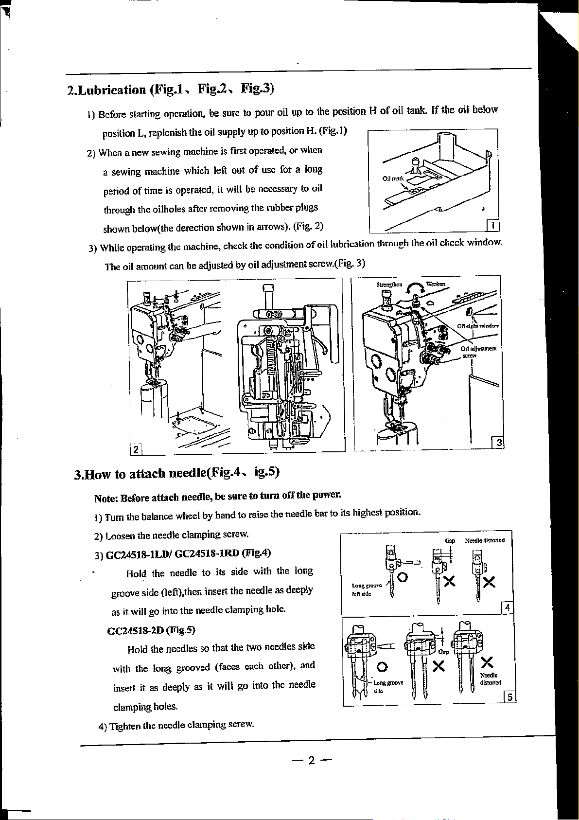
2.Lubrication
(Fig.l,
Fig.2,
Fig.3)
I) Before starting operation, be sure to pour oil up to the position H
position
2) When a new sewing machine is first operated,
a sewing machine which left out
period
through the oilholes after removing
shown below(the derection shown in arrows). (Fig.
3) While operating
The oil
L, replenish the oil supply up to position H. (Fig.])
or
when
of
use
for a long
of
time
is
amount
operated,
the
machine,
can
be
it
will be necessary to oil
the
rubber plugs
2)
check
the condition
adjusted by oil adjustment screw.(Fig. 3)
of
oil lubrication through the oil
of
oil tank.
If
the oil below
check
window.
3.How to
Note: Before
1) Turn
2) Loosen
3)
GC245!S.ILDI
groove side (left),then insert
as it
GC2451S.2D (Fig.S)
with the long grooved (faces each other), and
insert
clamping holes.
4)
Tighten
attach
the
the
Hold the needle to
will
Hold the needles so that the two needles side
needle(Fig.4, ig.S)
attach
balance wheel by
go into the needle clamping hole.
it
as deeply as it
the
needle,
needle
clamping
GC24518-IRD
needle
clamping
be
sure
to
turn
hand
to raise the needle
screw.
(Fig.4)
its side with the long
the
needle
will
go into the needle
screw.
off
as
the
deeply
power.
bar
to
its highest position.
!eh
""''"""
s!de
0 X
X
-2-
Page 4
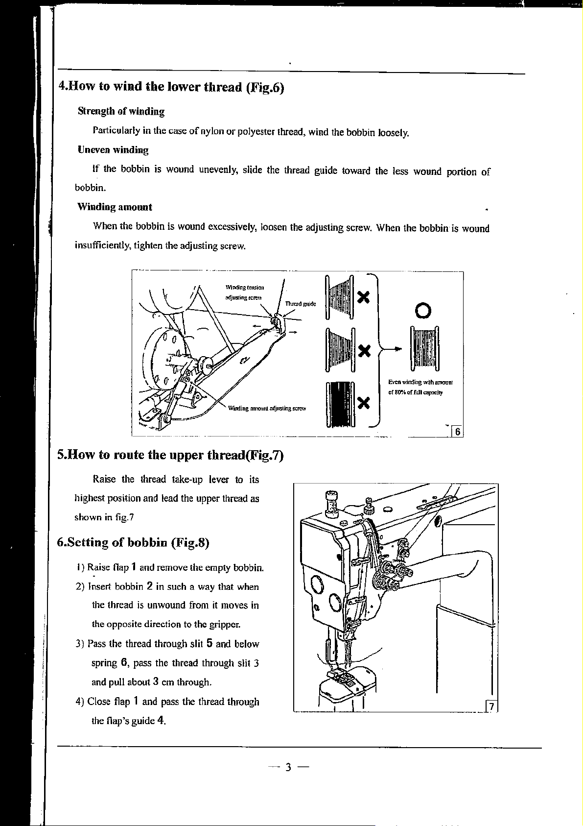
4.How to wind
the
lower
thread
(Fig.6)
Strength
Uneven
bobbin.
Winding
insufficiently, tighten the adjusting screw.
of
winding
Particularly in the
winding
If the bobbin
amount
When
the bobbin is wound excessively, loosen the adjusting screw.
case
of
nylon
or
polyester thread, wind the bobbin loosely.
is
wound unevenly, slide the thread guide toward the less wound portion
Wonding
:nnonnl
odjusling
SCI'Oif
X
X
When
Even winding
of
80%
the
bobbin
0
I
1¥i!h
a!
full~
ammmr
is
wound
of
S.How to route
Raise the thread take-up lever to its
highest position and lead the upper thread as
shown in fig. 7
6.Setting
I) Raise flap 1 and remove the empty bobbin.
2) Insert bobbin 2
3) Pass the thread through slit 5 and below
4) Close flap 1 and pass the thread through
of
the thread is unwound from
the opposite direction to the gripper.
spring 6, pass the thread through slit 3
and pull about 3
the
upper
bobbin (Fig.8)
in
such a way that when
em
through.
thread(Fig.7)
it
6
moves in
the flap's guide 4.
-3-
Page 5
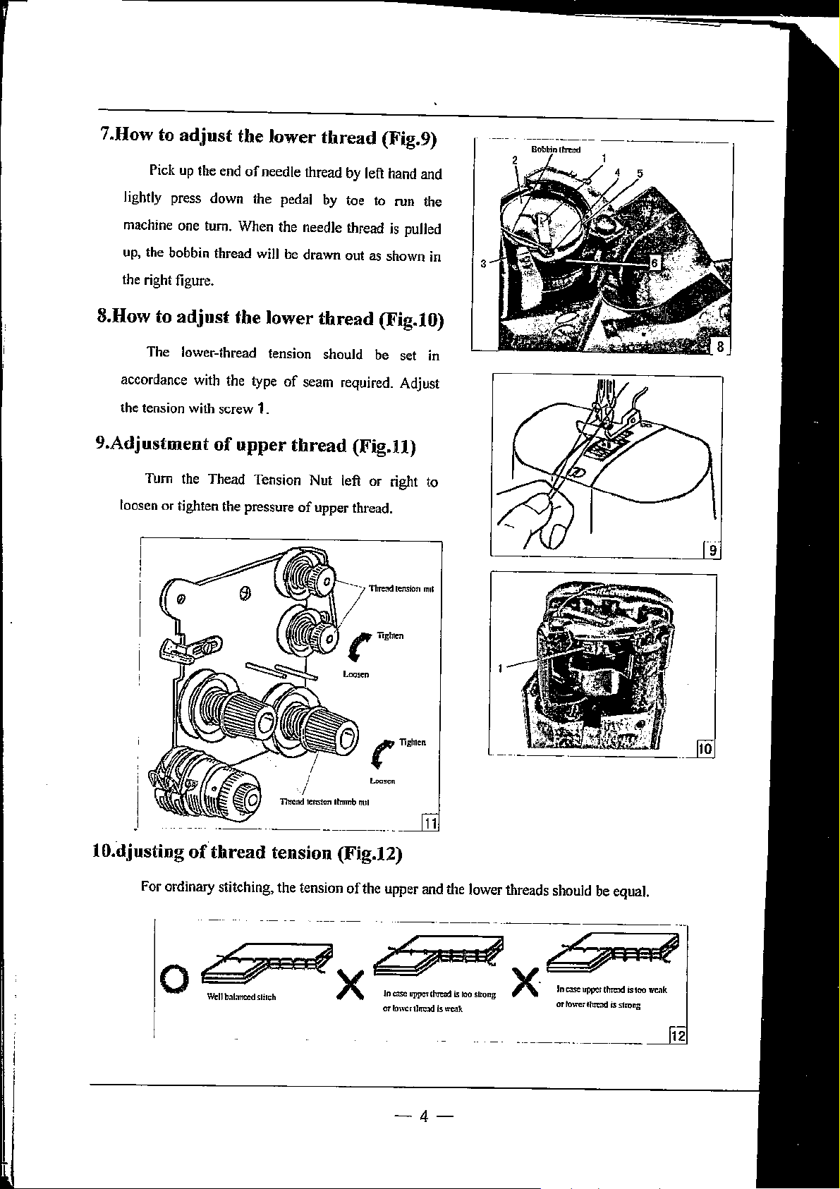
7.How to ad.just the lower
Pick
up
the end
of
needle thread
thread
by
left hand and
(Fig.9)
lightly
machine one tum. When the needle thread
up,
the right figure.
8.How to
accordance with the type
the tension with screw 1.
9.Adjustment
loosen or tighten the pressure
press down the pedal
the bobbin thread
adjust
The lower-thread tension should be set
of
Tum
the
Thead Tension Nut left or right to
will
be
drawn out as shown
the lower
of
seam required. Adjust
upper
thread
of
thread
upper thread.
by
toe
to
run the
is
pulled
(Fig.lO)
(Fig.U)
11!1'etld
ternjon
in
in
mol
'
.1
lO.djusting
For ordinary stitching, the tension
··-·--
of
thread
( llghlen
~=
tension (Fig.12)
of
the upper
-4-
and
the lower threads should be equal.
12
Page 6
;n.Adju•:tm.eut
of
stitch length
and
reverse sewing (Fig.13)
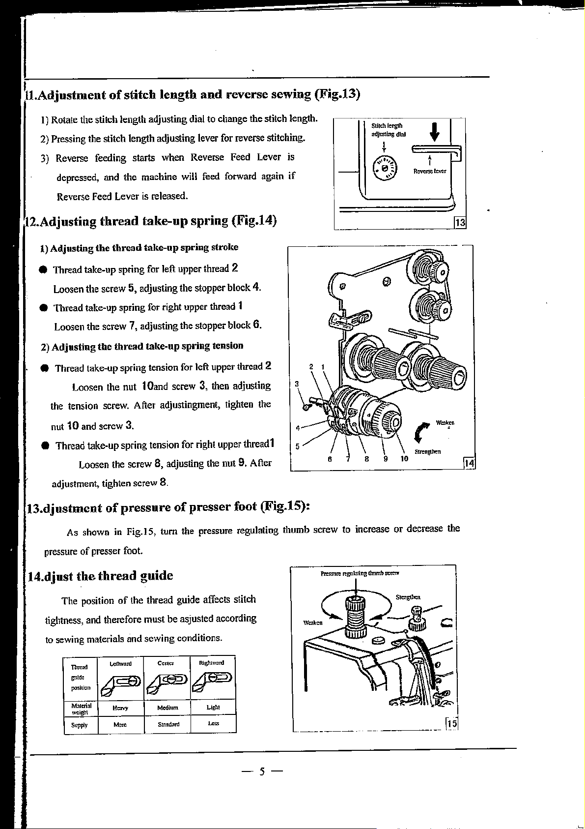
I) Rotate the stitch length adjusting dial to change the stitch length.
2)
Pressing the stitch length adjusting lever for reverse stitching.
3)
Reverse feeding starts when Reverse
depressed, and the machine
Reverse Feed Lever
;12.Ad.jus1ting
l)
Adjusting the thread take-up spring stroke
thread
is
released.
take-up
will
spring (Fig.14)
Feed
Lever
feed forward again if
e Thread take-up spring for left upper thread 2
Loosen the screw 5, adjusting the stopper block 4.
e Thread take-up spring for right upper thread 1
Loosen the screw 7, adjusting the stopper block 6.
2) Adjusting
• Thread take-up spring tension for left upper thread 2
the
thread
Loosen the nut 1
take-up
Oand
spring
screw 3, then adjusting
tension
is
1-
-------------
···-
SU!dt
lenglh
adJns!lns
l
0
dlnl
t-
I
R~lowr
-'l
[13
the tension screw. After adjustingment, tighten the
nut 10 and screw 3.
e Thread take-up spring tension for right upper thread1
Loosen the screw 8, adjusting the nut 9. After
adjustment, tighten screw 8.
(l3.dj1ost1ment
As shown
pressure
l4.d,iust
The position
tightness,
to
sewing materials and sewing conditions.
-·
~"
pcr.;iticn
f-=;
Moteriol
m::iglll
Supply
of
presser foot.
the
thread
and
therefore must
p
of
pressure
in
Fig.
IS, tum the pressure regulating thumb screw to increase or decrease the
of
presser foot (Fig.15):
guide
of
the thread guide affects stitch
be
asjusted according
L<:llw:lrd
"""
-~
CenlCI"
p>
Medilom
Stnnd.ml
Rlglnw:m:l
F
LiGht
~
5
-5-
Page 7
15. Installation
of
Belt cover (Fig. 16)
Set the screw
illustrated. Assemble the belt guard 3 in the direction
of
the arrow, tighten it's screw. The assembling
belt guard 5
the belt guard 1 from the top
inside
of
the 3 and
4,
6 and the washer 7 on the arm as
is
the same as the belt guard
of
5,
tighten the screw2.
3,
then, insert
the pulley into the
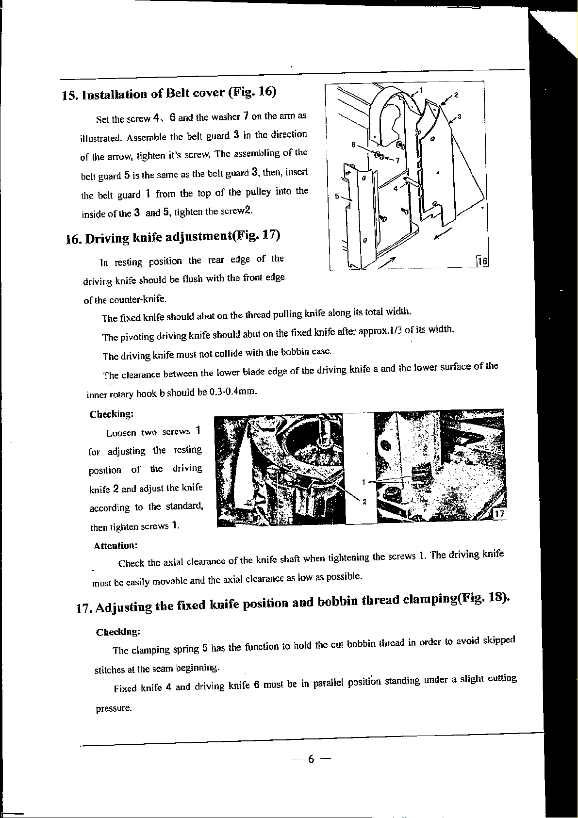
16. Driving knife adjustment(Fig. 17)
In
resting position the rear edge
driving knife should be flush with the front edge
of
the counter-knife.
The fixed knife should
The pivoting driving knife should abut on the fixed knife after approx.
The driving knife must not collide with the bobbin case.
The clearance between the lower blade edge
inner rotary hook
b should be
abut
on
0.3~0.4mm.
of
the
the thread pulling knife along its total width.
of
the
'
•
---
1/3
of
its width.
of
the driving knife a and the lower surface
- _ji6
of
the
Checlring:
Loosen two screws 1
for adjusting the resting
position
knife
according to the standard,
then tighten screws
Attention:
must
17. Adjusting
Checking:
stitches at the seam beginning.
of
the driving
2 and adjust the knife
1.
Check the
be
easily movable and the axial clearance as low as possible.
The clamping spring 5 has the function to hold the cut bobbin thread
Fixed knife 4 and driving knife 6 must be
ax.ial
the
fixed knife position
clearance
of
the knife shaft when tightening the screws
and
hohhin
in
parallel positiOn standing under a slight cutting
thread
1.
The driving knife
clamping(Fig. 18).
in
order to avoid skipped
pressure.
-6-
Page 8
Parallel position correction
Loosen screw 3 slightly for adjusting the
counter-knife 4, then change counter-knife 4
thread pulling knife and counter-knife are
in
parallel position
by
setting the screws 2
parallel position. Tighten screw 3 at last.
of
thread pulling knife 6 and
in
such a way that the edges
Cutting pressure adjustment
The knives should guarantee a safe cut at the lowest possible pressure
the thread
thread pulling knife with a knife overlapping
last, tighten screws
pulling knife. This
Loosen screws 1, then tum counter-knife support in such a way that the condition is fulfilled, at
1.
is
nonnally the case when the edge
of
l/3.
of
of
the counter-knife against
the counter-lmife just touches the
of
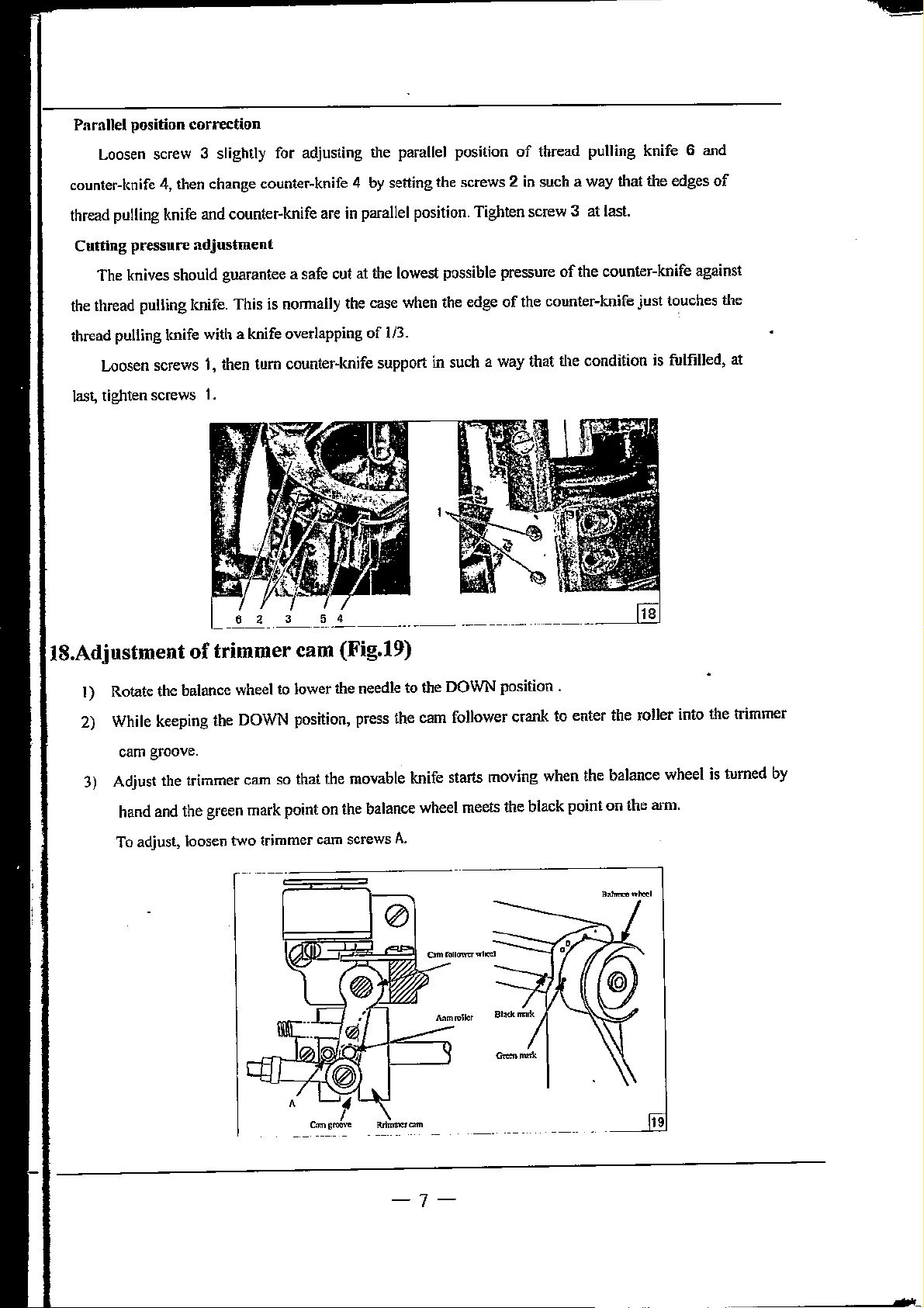
1)
Rotate the balance wheel
2) While keeping the DOWN position, press the cam follower crank
cam
groove.
3)
Adjust the trimmer cam so that the movable knife starts moving when the balance wheel is turned
hand and the green mark point on the balance wheel meets the black point on the arm.
To
adjust, loosen two trimmer cam screws
to
lower the needle to the DOWN position .
A.
to
enter the roller into the trimmer
19
by
-7-
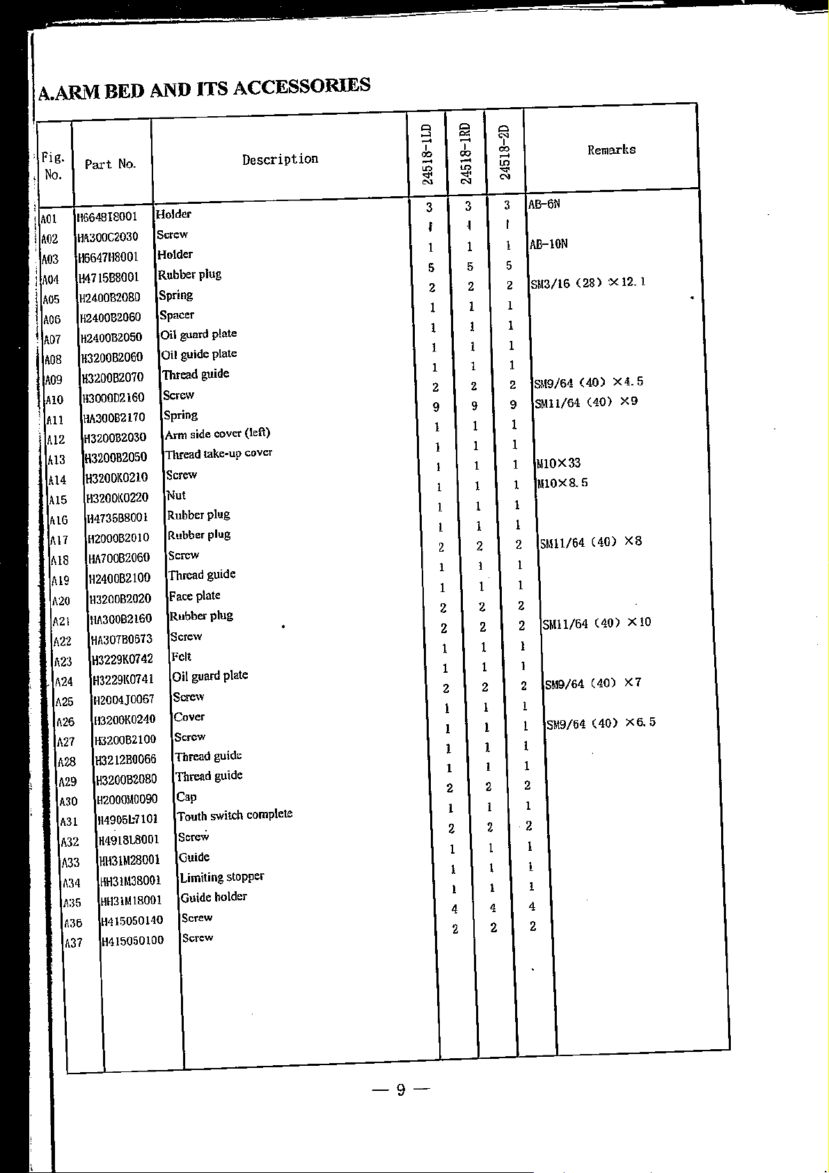
Page 9
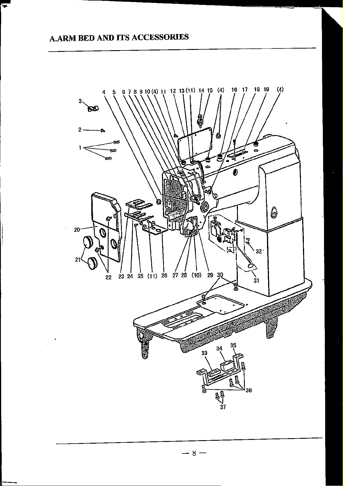
A.ARIVI
BED AND
3~
ITS
ACCESSORIES
2
..
22
(11)
-8-
Page 10
A.AR\VI
BED
AND
ITS ACCESSORIES
Part
No.
Description
complete
0
~
-
~
' '
~
-
..
N
3
1
5
2
1
1
1
1
2
9
1
1
1
1
1
2
1
1
2
2
1
1
2
1
1
1
2
1
2
1
1
4
2
iii
-
~
-
~
N
3
1
5
2
1
1
1
1
2
9
1
0
'i'
~
~
-
..
N
3
1
5
2
1
1
1
1
2
9
1
1
1
1
1
1
1
1
1
1
2
2
1
1
1
2
2
2
2
1
1
1
2
2
1
1
1
1
1
1
1
2
2
1
1
2
2
1
1
1
1
1
4
4
2
2
Remarks
(28)
'Xl2.1
(40)
(40)
(40)
(40)
(40)
(40)
X4.
X9
X8
X7
5
XlO
X6.5
-9-
Page 11
I
I
I
'
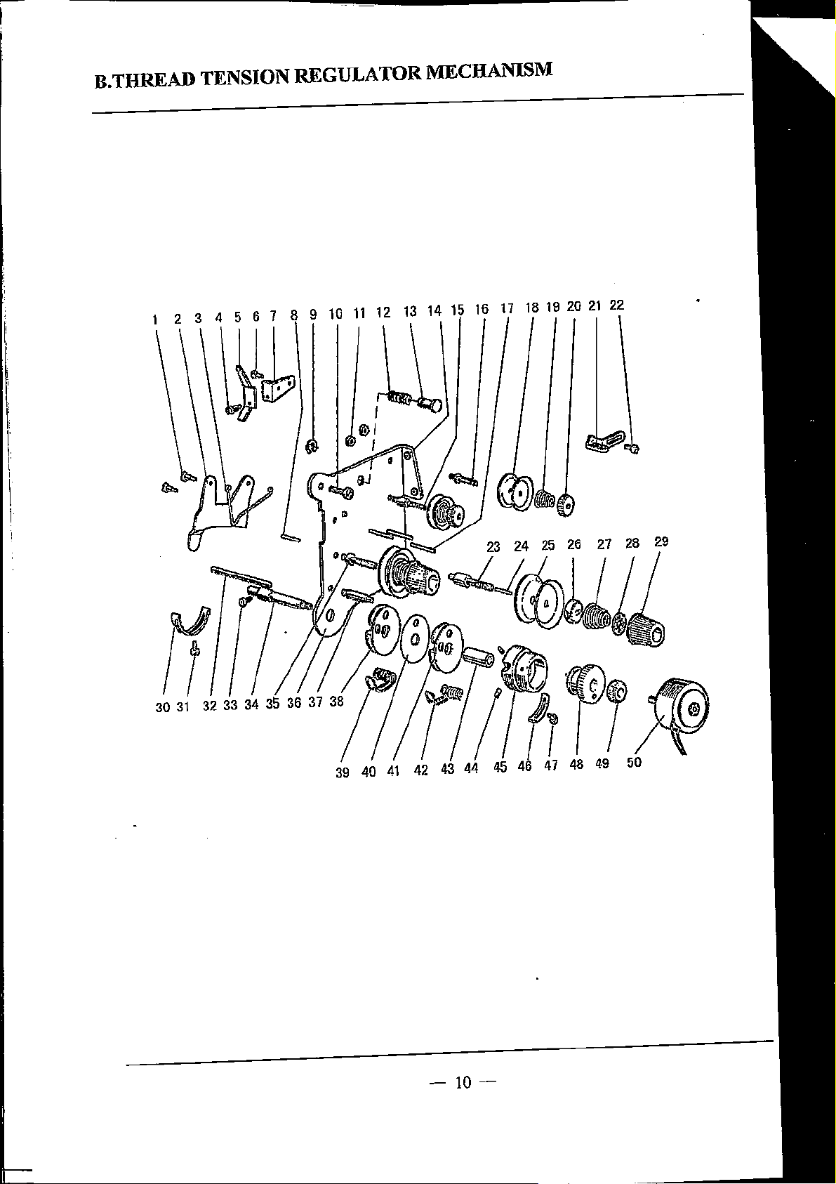
B.
THREAD
1 2 3 4 5 6 7 8 9
TENSION REGULATOR
10
11
12
13
.lb
MECHANISM
17
18
14
16
19
20
21
22
I
30
31
32 34
-10-
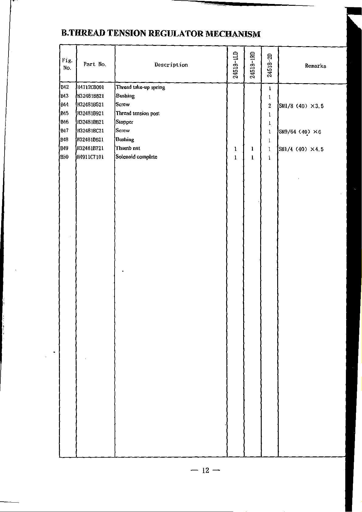
Page 12
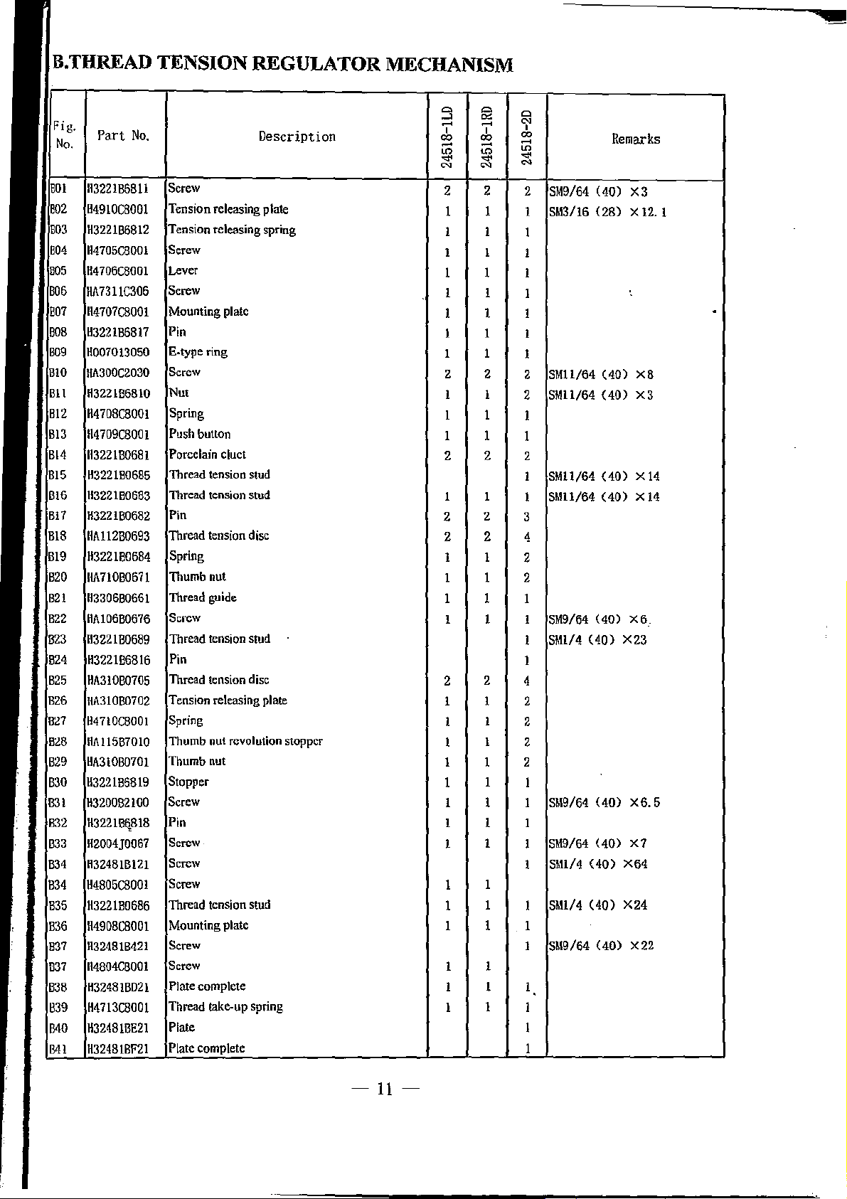
THREAD
TENSION
REGULATOR
MECHANISM
Part
No.
Description
spring
c\uct
tension stud
tension stud
uut
guide
tension stud
tension disc
nut revolution stopper
uut
tension stud
complete
take-up spring
Q
fi!
~
- -
ro ro
' '
~
~
-
-
~ ~
~
~
2 2 2
1 1 1
1 1
1 1 1
1 1
1 1 1
1
1 1
2 2
1
1
1 1
2 2 2
1 1
2
2
2 2
1 1
1 1 2
1 1 1
1 1 1
2
2
1 1 2
1 1 2
1
1
1 1 1
1 1 1
1
1
1
1
1
1
1 1 1
1 1
1 1
1
Q
~
ro
~
-
~
~
2
2
1
3
4
2
1
4
2
2
'
1
1
1
1
1
1
1
1
1
1
1
(40)
(28)
(40)
(40)
(40)
(40)
(40)
(40)
(40)
(40)
(40)
(40)
(40)
Remarks
X3
X 12. 1
XB
X3
Xl4
Xl4
X6_
X23
X6.5
X7
X64
X24
X22
-11-
Page 13
B.
THREAD
TENSION
REGULATOR
MECHANISM
Fig.
No.
Part
No.
spring
complete
Description
0 0
~
~
-
-
ro ro
' '
~
~
-
-
..
..
N N
1 1
1 1
0
N
ro
'
~
-
..
N
1
1
2
1
1
1
1
1
Remarks
(40)
(40_)
(40)
X3.
X6
X4.
5
5
-12-
Page 14
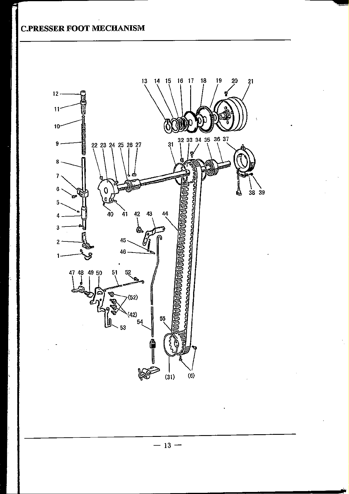
C.PRESSER FOOT MECHANISM
13
10
9
8
7
6""'-
.,
5~
4---'!"1
3-
R
2-l
1----\P
47 48 49
~
22
41
45~
46
50
51
52
.....
..-->
42
43
~_b
"'
54
53
"-._
1
~
(31) (6)
-13-
Page 15

---
C.PRESSER FOOT MECHANISM
Fig.
No.
Part
No.
foot complete
bar guide bracket
Description
foot
spring guide
command disk F20 (up)
command
"""'
disk
Fll
(down)
bracket (complete)
~
"'
-
00
'
~
-
~
N
1
~
N
"'
"'
-
00
00
~
-
~
N
1
1
1
1
3
1
1
1
1
1
1
1
1
1
1
2
1
2
1
1
1
1
1
1
3
1
1
1
1
1
1
1
1
1
1
3
'
'
~
-
~
N
1
1
1
1
1
1
1
1
1
3
3
1
1
1
1
1
1
1
1
1
1
1
1
1
1
1
1
1
1
1
1
1
2
2
1
1
2
2
1
1
1
1
1
1
1
1
1
1
1
1
1
3
3
1
1
1
1
1
1
1
1
1
1
1
1
1
1
1
1
1
1
3
3
1
1
1
1
1
Remarks
(44)
't28)
(28)
(28)
(28)
(28)
(40)
(40)
X9
(28)
(28)
(28)
Xl4
X10
Xl2
X13
X10
Xl4
X4
XB
X12
X6.
7
-14-
Page 16

C.PRESSER
FOOT
MECHANISM
Fig.
No.
C46
•17
COB
C49
C50
C51
C52
5.1
C54
C55
Part
No.
H3200E2090
H3208E0067
HAIOOBZllO
H3200E2060
H32JOE0682
H32\0E068!
HA107H0662
H32IOE0683
H6307E800!
H3207C067l
Description
Pin type
Presser har lifter
Screw
Eccentric
Knee lifter lever left
Knee lifter rod
Screw
Operation plate
Operation rod
Pulley
Q Q
~ ~
-
-
00
-
~ ~
f f
N
'
00
'
-
N
I I I
I
I I
2
2
I I
1 1
1 1 1
3
3
1 1 1
1
1 1
I 1 1
Q
N
00
'
-
~
f
N
SMll/64
2
I
1
S~\3/16
3
SM9/64
Remarks
(40}
(28)
(40)
X5. 5
.
xz. 5
X6
.
-
15-
Page 17

D.NEEDLE BAR AND THREAD TAKE-UP MECHANISM
17
16
14
1-----,1'1
-16-
Page 18

D.NEEDLE BAR AND THREAD TAKE-UP MECHANISM
Part
No.
Description
bar connecting stud
pulley
lever
Q
§l
~
- -
~ ~
'
~ ~
- -
~ ~
N N
1 1
1
1 1
2
4
1
4
2 2
1
1 1
1
1
1 1
1
3
1
1
1
1
1
1
2
2
1 1
1
1
2
1 1
1
1
Q
N
~
'
~
-
~
N
1 1
2 2
4 4
1
4 4
1
1
1
1
3 3
1
1
1 1
1
1
1
1
2 2
2
1 1
1
1
1
2
1
1
1
1
1
'
2
1
1
1
2
1
1
1
1
1
1
1
1
1
1
1
2
1
1
1
1
2
1
.1
1
1
Remarks
#18
(56)
(40)
(44)
(28)
(40)
(28)
(24)
(44)
(24)
(24)
X4
X8.5
X3.
X 12
X6
Xl5
X4. 8
X5. 5
X26.2
5
X7
-17-
Page 19

D.NEEDLE BAR AND THREAD TAKE-UP MECHANISM
Q
Fig.
No.
Part
No.
Description
Q
~
-
~
'
~
-
...
N
1
"'
-
~
'
~
-
...
N
1
1
Q
N
~
'
~
-
...
N
Remarks
(44)
X4.5
-18-
Page 20

E.STITCH REGULATOR MECHANISM
.262728
30
16 17
18 19
20
\x~~
1\
36 37 38 (31) 39
40
-19-
41
42
(31)
Page 21

E.STITCH REGULATOR MECHANISM
Fig.
No.
Part
No.
I"''"'"
pin
stitch
Description
shaft
(upper)
Q
~
00
m
N
~
Q
Q
N
"'
-
00
'
2
1
m
N
~
m
-
~
N
2
2
IS>lll/" ( 40)
1
1
'
00
'
Remarks
(28)
X8. 5
X
(28)
(28) X 12
12
X 8. 5
(28) X 12
xs.
5
(28)
X8.5
(28)
X7
1
(28)
X6
1
-20-
Page 22

F.LOWER SHAFT AND FEED ROCK SHAFT MECHANISM
1 2 3 4 6
22
23
24
25
26
~
-21-
Page 23

F.LOWER SHAFT AND
Fig.
No.
Part
No.
shaft bushing (left:)
shaft bushing (right)
shaft bushing complete (middle)
bearing
bearing
connecting fork
;
ring C-type
flange
shaft bushing
shaft
shaft crank(right)
FEED
ROCK
Description
(left)
SHAFT
Q
~
-
00
~
~
N
MECHANISM
Q
Q
~
N
00
'
00
'
'
~
-
~
-
~
~
N
N
1
1
1
1
1 1
3 3 3
1
1
1 1
1 1
1 1
3 3 3
2
2 2
1 1
1 1 1
1 1
3 3
1
1 1
1
1
1
1
1
1
1
1
1
1
1
1 1
3
1
2 2 2
2 2 2
2 2 2
2 2 2
2 2 2
Remarks
(40)
X5
(28) X 14
(28)
(24)
X4
(28)
X7
(44)
X4
(24)
X22
(24)
X3.5
(28)
(28) X 12
Xl4
Xl8
-22-
Page 24

F.LOWER
Fig.
No.
F44
F45
F46
H7
F-IH
F49
F50
F~l
F52
Part
HAIOOG2120
HA105D0652
HA106G0661
fl:l208G0676
H:l208G0673
H3206D0674
H2012N0652
H32311D306
H32311D406
SHAFT
No.
AND
Bushing
Screw
Collar
Screw
Connecting rod crank( middle)
N"t I
Screw
Screw
Oil wick
FEED
Description
ROCK
SHAFT
N
MECHANISM
Q
~
-
m
-
~
N
4
Q
N
ro
'
'
-
m
~
N
I
I
SMI/4
4
2
2
I
I
I
SM15/64 C28) X
I
I
SMS/16
I
SMI/4
I
I
SMS/16 C24) X26. 2
I
9
-
ro ro
'
-
m
~
I
4
2
I
I I
I I
I I
I
(24)
(24)
(24)
Remarks
X4
14
.
X5
XIS
.
-23-
Page 25

G.HOOK SADDLE MECHANISM GC24518-1LD (
1)
4 5 6 7 8
~
18
19
20
••
•
0 0
13
~
.,
..
•
-24-
Page 26

G.HOOK SADDLE MECHANISM
GC245l8-lLD
(2)
46 47 48
~~
::~
43
""'
42'\~-
41
51
52
53
54
55
56 57 58 59
49
50
11
60
61
62
l~/(40)
I·~
I
'!
63
64
(38)
66
67
-25-
Page 27

G.HOOK SADDLE MECHANISM GC24518-ILD
Q
Q
_,
Fig.
No.
l'art
No.
Description
-
'
~
~
-
.,.
~
~
00
~
.,.
~
Q
~
00
'
'
~
..
~
Remarks
complete
I
I
2
2
2
('>4\0.0)
5X4
X 5
3
6
8
2
8
4
-26-
ll/4\4WX6.5
(40)
X6
Page 28

G.HOOK SADDLE MECHANISM GC24518-1LD
Fig.
(',.14
G4.'i
G4fi
G47
G48
G-1\l
GSO
(;51
Gfi2
GS:l
G54
G55
G56
{;57
G58
G59
GUO
GGI
Gfi2
G63
GG4
Gfi!i
(;(,()
Gfi7
Ghli
(;(i9
Part.
No.
H40I030060
HG171]8001 Spring
No.
HG164J7101
HHIOI58001
HD726G8001
HHIOI68001
HGI77JBOOI
!f(jQ4020 180 Taper pin
HGJHZJBOOJ
HG!Bi]BOOI
H427040060
HG90]7BOOI
H415040370
H007013060
HGJ56]800I
HGI55]8001 Pin
1-11-131118001
HG91]88001
H428050080
H003008050
HG91}98001
Hfi31Jl8001
H'2000MOI'20
HG9l]58001
H41.'i060250 Screw
Hll31
I2800i
Screw
Cover
Needle plate
Screw
Feed
dog
Screw
Screw
Adjust cover
Screw
Transp.column
Screw
E-type
ring
Square block
Transp.lever
Cover
plate
Screw
Nut
Cover
Screw
Nut
Plate Holder
Plate
Description
Q Q
~
~
-
-
00 00
'
~ ~
- -
~ ~
~ ~
l
l
l
l
2
l
l
l
2
2
l
l
l
l
l
l
l
l
l
l
l
l
l
l
4
l
Q
~
'
00
'
~
-
f
~
Remarks
.
.
-27-
Page 29

H.HOOK SADDLE MECHANISM GC245l8-lRD (
l)
11
12
13
14
15
16
Y------31
~32
•
iJ_-30
~
~35
.._________
17
.-4----18
! 19
33
34
36
-28-
Page 30

H.HOOK SADDLE MECHANISM GC24518-1RD
52
53
47
48 49
50
51
54
(2)
55
56
57
58
42
39
38
37
59 60
\\
0
61
64 65
(44)
· .
66
(43) (50)
~
~
1!9l..
.., E ..
(49)
67
J
,---~
[f-,-,-1,
• I
..
I···
• I '
•II
'·
•
--~
·:
~
1
~~
II
·1K-1:
•J
1 tf
r·l·
:
I
~
••
1 r. I 1
~
.
·~
...........
69
68
;I:
1:
:~t,sl
II
I!
,.
~
..,
~.
<r
..
-·
..
(65)
..
-29-
Page 31

H.HOOK SADDLE MECHANISM GC24Sl8-lRD
~
"
Fig.
No.
Part
No.
Description
complete
"
-
00
'
~
-
~
"
"'
-
00
'
~
-
~
"
1
2
2
1
1
2
1
1
1
1
1
1
1
1
~
"
00
~
-
~
"
'
Remarks
5)X5
-30-
ll/4(4.0)
3
1
1
8
8
1
1
(40)
X6.
5
X6
Page 32

H.HOOK
Fig.
No.
Part
SADDLE
No.
MECHANISM
Description
GC24Sl8-lRD
Q
~
"'
"'
-
-
'
~
~
~
- -
..
N N
'
~
..
Q
N
~
'
~
-
..
N
Remarks
HG182}8001
H44
H45
HD726GBOOi
Hl-l20I58001
H46
H47
HGI77jBOOJ
HH20I6800l
H48
HGJ9Ij8001 Sorew
H49
H50
HG163J8001
H!il
HG91J58001
HG2
H415040370
Hf/:l
HG90j78001
H427040060 Sorew
H54
H!i5 HG164J7IOI
H50
H604020180
H57
HG171JBOOl
H40!030060 Snew
H58
H6311IBOOI
H59
Hl-13Jl!BOOI
HfiO
H2000MOI20
H61
HGi55JB00! Pin
Hfi2
H!i3
HGI56JB001
H007013060
H64
H65
H005001060
HliG
H415060250
Hli7
tll-l3ll2800I
HG90)88001
HliB
Hfi9
HG!JIJ4800I
Screw
Sorew
Needle plate
Screw
Feed dog
Sorew
Plate Holder
Screw
Transp.coiUitU1
Cover
Taper pin
Spring
Screw
Transp.lever
Nut
Square
block
E-type
ring
Washer
Sorew
Plate
Cover
plate
Plate Holder
I
2
I
I
I
2
4
I
I
I
I
I
I
I
I
I
I
I
I
I
I
6
4
I
2
I
.
.
-31-
Page 33

I.HOOK SADDLE MECHANISM GC24518-2D (
@ (1)
~
~--~
I
1._
I
~~r-
j~
L~(3)
1)
!
-----
i
(2)
~"'
18 •
19
20
~
0 0
,.
.
•
FJ-(30)
Y-------(31)
~(32)
0
~
~(35)
..._______ (36)
(33)
(34)
-32-
Page 34

I.HOOK SADDLE MECHAi'IISM GC24518-2D
(2)
44
43
40
39
--o::=::;,,"l--iP!f:,=?.:l---11
38--+
37~:
I
-~
46 47 48 49
::,.6~
~·
(64)
50
51
52 53
54
(1)
55
(43)
__......-(40)
rv---'(42)
IJ
...___
(41)
(37)
(38)
(63)
56 (55) (37) 57 58 59
-33-
60
61
62
63
64 65
Page 35

I.HOOK SADDLE MECHANISM GC245l8-2D
~
Fig.
No.
!•art
No.
Description
"
-
00
'
~
-
.,.
~
"
"'
-
00
'
~
-
~
""
~
"
00
'
~
-
~
""
2
2
2
4
••
2
2
4
2
2
2
2
2
2
2
2
2
2
2
2
2
2
2
2
2
2
2
2
2
2
2
2
6
2
2
2
8
2
2
2
2
2
2
(0. 5)
5X4
Jl/4\0UJ
(40)
Remarks
X5
X6.
5
X6
-34-
Page 36

!.HOOK SADDLE MECHANISM GC245l8-2D
Fig.
!44 HH3JI6800l Needle plate
!45
146
!47
l4H
149 HH31I58001
150 H415040370
IfJ
152 HGI50J800I
lfJJ
154
155
IS!i
!57 Hfi3III800I Screw
!58 HH3lli8001
!59
160
!61
!62
IG3
!64
Ifi5
I fi!i
Hi7
Part
No.
HGJ75J8001
HGI8l]8001 Adjust cover
HG!82J8001
HGJ77J800l
I
HG169]8001 Guide plate
H427040060
HGI91]8001
HG162J800l
HG163JBOOI
HG155J8001
H2000M0120
HGJ56J800!
H007013060
No.
H00500I060
H4l5060l60
H401035080
H415060250
HH31
128001
Screw
Sorew
Screw
Feed
dog
Screw
Transp.column
Screw
Screw
Cover
pJate(left)
Screw
Transp.lever
Pin
Nul
Square block
E-type ring
Washer
Sorew
Screw
Screw
Plate
Description
Q
§
~
- -
00 00
' '
~ ~
- -
.. ..
N
N
Q
N
00
'
~
-
..
N
I
2
2
2
I
I
I
I
1
1
2
2
8
1
I
1
I
1
1
8
8
2
4
1
Remarks
-
-
-35-
Page 37

J.OIL LUBRICATION MECHANISM
1 2 3
(1)
10
11
12
H/----+--24
......,,CC--
'
)
373635 34 33
......,-(23)
'---
28
(1
0)
(1)
27
-36-
....
Page 38

J.OIL LUBRICATION MECHANISM
Fig.
No.
Part
No.
Description
@
~
"
-
-
~ ~
~
-
.. ..
~ ~
'
'
~
-
~
"
~
'
~
-
..
~
Remarks
)01
HA300C2030
)02
H3200K0050
)03
H32422C208
)04
~32175B304
)05
H3204K0032
H3204K0043
J06
.J07
H3204K00ll
)OR
H4ll040160
JO!l
H3200K0030
)10
HA300B2170
)II
H3200K0040
112
H3209K0065
H3200K0180
J
13
H3216K0070
Jl4
)15
H323IID606
jl6
H3200K0160
)17
H3218K0072
)18
H3217K007I
)19
H3200K0170
)20
HA300B2130
)21
HAIOOE2l50
.}22
H3200K0250
)23
H3200K0190
H6304K800l
.J24
J25
H6305K800l
j2(i
H3200K0200
H3230K075I
J27
H3230K0752
J28
J29 H32I5K0696
)30
Hll0012070
)31
HI
10012080
)32
HllOOI2llO
.J33
H3204D6510
)34
H3215K0693
)35
H3215K0692
)36
H3215K0694
)37
H3215K40ll
H32151<0695
.J38
]39
HAl0680676
Sorew
Ho1deo-
Rubber
Felt
Oil pipe complete
Oil pipe complete
Oil pipe complete
Screw
Holder
Spring
Holder
Oil
Oil
Oil
Holder
Holder
Oil pipe complete
Oil pipe complete
Holder
Sorew
Screw
Holding plat
Holder
Oil pipe
Oil pipe
Holder
Screw
Bushing
Oil
Pm
Spring
-
Spring_
Screw 1 1 1
Screw 1 1
Filter
Screw 1 1 1
Mounting
Holder 1 1 1
Screw
plug
pipe complete
wick
pipe complete
pipe
holder
plate
complete
4 4 4
I I I
I
I I
2 2 2
I
1 I
I I
1 1 1
2 2 2
1 1 1
2 2 2
1 1 1
1
1 1
3 3 3
1 1
1 1 1
3 3
1
1 1
1 1 1
1 1
5 5 5
2 2 2
I
1 1
2 2 2
1 1 1
1 1 1
1 1 I
2 2 2
1 I I
1 1
I I I
1 I 1
1 1 1
1 1
1 1
1
1 1 1
•.
1
1
3
1
1
1
I
-
.
-37-
Page 39

"
1
..
-)"
,,
'
t
l
K.KNIFE
MECHANISM
678910
11
12
13
14
.
15
16
1 2
~v
. -
"'
\
17
3 4
....
/J
18
19
...
(17)
22 23 24
25
32
\
(21)
I
L
____
27
28
29
30--~'
31
(20)
•
26
l
I
38
39
-38-
40
41
42
43
44
45
Page 40

K.KNJFE MECHANISM
Fig.
No.
KOl
K02
K03
K04
K05
K05
K05
K07
KOB
K09
KlO
Kll
Kl2
Kl3
Kl4
Kl5
Kl5
Kl7
Kl8
Kl9
K20
1{21
K22
K23
K24
K24
K25
K26
K27
K28
K29
K30
K3l
K32
K33
K34
K35
K35
K37
K38
K39
K40
K4l
Part
No.
H4907K8001
H73!4G8001
HH3IM5800I
HH30M4800l
H4909K8001
HHIOM58001
HH30M58001
H4913K8001
H003002050
HH30M8710l
H4945K8001
HA113F0684
H6904]8001
HA710E0692
HH3Hl6800l
H431050050
H4934K8001
H4905K8001
H005001050
H4911K8001
H4936K8001
H3405D0663
~160
17H800
I
HH32Ml800I
H3405D0661
HHIOM68001
H4963K8001
H431050050
H4ll050160
H4965K8001
H2012N0652
H4983K8001
H49671\8001
H4973K8001
H4974K8001
H4977K8001
H498IK8001
H4979K8002
H003008050
HAIIIG0683
BA7111N304
H4972K800I
H4971K8001
0
~
IE
- -
00
Description
Screw
Washer
Ann
Link
Link
Ann
A~
Screw
N"t
Vibrating crank complete
Spring
Screw
Bushing
Screw
Crun
Screw
C•m l
Screw
Washer
Bolt
Screw
Link
Spring
Mounting plate
Screw
bar
Screw bar
Sboft
Screw
Screw
Set plate
Screw
Screw
Screw
Pin l l
Ann
Mounting plate
Holder
Solenoid complete
Nut 2 2 2
Screw
N"t
Screw l l
Lever l l I
00
'
~
-
~
N
'
~
-
~
N
l
l
l l
2 2
l l
l l
2
2 2
l l
2
2 2
l
l l
2
2 2
l l
2 2 2
2 2
l l
l l l
l l
l
l
l l
2 2 2
2
2 2
l
l l
l
l l
l
l l
2 2
l l l
l l l
l l l
l l
l l l
l l l
0
N
00
~
-
~
N
'
2
l
2
l
2
2
2
2
2
Remarks
l
l
l
l
.
l
l
l
M5X5
.
l
M5X5
M5X16
l
l
l
-39-
Page 41

K.KNIFE MECHANISM
Fig.
No.
Part
No.
Description
0
~
iii
~
~
J,
ro
~
~
~ ~
..,.
..
N N
1 1
1
1 1
1 1
0
N
ro
'
~
~
..,.
N
1 1
'
1
1
1
Remarks
-40-
Page 42

L.ACCESSORJES (
11
10~
g---~
1)
..----------
14
p:___--15
16
7
d~17
.--18
4
3
19
20
t--21
-11-
Page 43

L.ACCESSORIES
(2)
•
26 27
28
29
31
32
-42-
33
Page 44

L.ACCESSORIES
Fig.
No.
LOI
H801045200
L02
HA300J2230
L03
HA706S0067
L04
HAIOOJ2I80
L05
HA704S0654
L06
Hfi300]22IO
L07
HA300J2200
LOB
HA300J2070
L09
HBOIOOI015
LIO
HB0100l025
Lll
HBOlOOl030
LIZ
JZDP5000G1803
Ll3
HGl87J800l
Ll4
HAIOOJ2120
H3207L0065
Ll5
Ll6
H4705K800l
Ll7
H4706K800l
LIB
HA307J0067
Ll9
HAIOOJ2ll0
L20
H3200L0120
L20
HA200J2030
L21
HA120]8001
L22
H63IOL8001
L23
H0208L800I
L24
H6722N800l
L25
H0207L8001
L26
H6307L800l
L27
tl200000360
LZB
H6309L8001
L29
HA104J0652
HA104J0653
1.30
1.31
H32)3L0664
L32
HA104J0657
L33
H32l3l.0662
1.34
H3214l.0067
1.35
H3214l.20ll
1.36
Hfll04J6510
L37
HA300J2180
L38
HAI04J0659
L39
H007013090
L40
HH30l.5800l
L41
H2400K0080
Part
No.
Vibration preventing rubber
Washer
Bobbin winder
Vinyl cover
Adjusting plate for speed command disk
Screw driver (small)
Screw driver (middle)
Screw driver (large)
Sock!
wrench
Sockt wrench
Sockt wrench
Needle
Bobbin
Magnet
block
Thread a needle kit
Vibration preventing rubber
Vibration preventing rubber
Hinge complete
Oiler
Cotton stand
Cotton stand
Oil can
Belt cover (left)
Screw
Washer
Screw
Belt cover
Screw
Belt cover (right)
Screw
Washer
Knee
lifter crank
Spring
Knee
lift shaft
Small
parts
Knee
lifter pin
Description
for
reservoir
N"'
Screw
Screw
E-type ring
Oil
reservoir
V-belt
0 0
~
~
-
-
ro ro
'
~
~
- -
..
..
N N
2 2
2 2
1 1
1 I
I I
I
I I
I I
I
1 1
I 1
3 3
2
1 1
I 1
2
2
2 2
2 2
1 1
1 1
I I
I I
I
2
2
4 4
1 1
2 2
1 1
1 1
1 1
1 1
1 1
1 1
1 1
1 1
2 2
1 1
2 2
1 1
1 1
1 1
0
N
ro
'
'
~
-
..
N
2
2
I
I
I
I
1
I
I
I
I
I
1
DPX5
6
4
2
1
I
2
2
2
I
1
Remarks
-
#!B
.
1
1
I
1
2
4
1
2
1
I
1
I
1
1
1
1
2
1
2
1
1
1
h
I
'
-43-
Page 45

M.PNEUMATIC CONTROL UNIT
4 5 6 7
-44-
Page 46

M.
PNEUMATIC
Fig.
No.
Mill
M02
M03
M04
M05
M06
M07
M08
Part
H49J.'i~OOI
I!H30B88001
HA300B2170
H005008060
11415060200
H4914G8001
H4913G8001
H4916G8001
No.
CONTROL
Air cylinder
Arm
side cover (right)
Screw
Spring flange
Screw
"oin pole
Feeler
Windpipe joint
UNIT
Description
0
0
~
~
-
-
'
00
00
'
-
~
-
~
~
~
N
N
I I I
I
I I
4
4
4
4
4 4 4
I
1 I
I
I I
2 2 2
0
N
00
~
-
~
N
'
4
4
Remarks
.
-45-
...
 Loading...