


SHANGHAI HUIGONG NO.3 SEWING MACHINE FACTORY
GC2268-2B/2BL
Two Needle Cylindrical Bed Compound Feed
Lockstitch Sewing Machine
Instruction Manual
Parts Catalog

CONTENTS
INSTRUCTION MANUAL
一、PRECAUTIONS BEFORE STARTING OPERATION .................................... 1
1、Safety precautions ..................................................................... 1
2、Precautions before starting operation ....................................................... 1
3、Precautions for operating conditions ...................................................... 1
二、SPECIFICATIONS .................................................................. 1
三、CAUTIONS ON USE ................................................................. 2
1、Lubrication ........................................................................... 2
2、Winding of bobbin thread ................................................................ 2
3、Attaching the needle ................................................................... 3
4、Selection of thread ..................................................................... 3
5、Threading of needle threads .............................................................. 4
6、Setting of bobbin ..................................................................... 4
7、Threading of bobbin threads ............................................................. 5
8、Thread tension ........................................................................ 5
9、Thread take-upspring .................................................................. 5
10、Adjusting the stitch length .............................................................. 6
11、Adjusting the pressure of the presser foot ................................................. 6
12、Adjusting the presser foot and the walking foot .............................................. 6
13、Timing between rotating hook motion and needle motion ..................................... 7
14、Relationship between hook motion and opener motion ........................................ 7
15、Relationship between needle motion and feed dog motion ..................................... 7
16、Adjusting the height of the feed dog ..................................................... 8
17、Safety mechanism .................................................................... 8
18、Adjustment of needle bar stop position (GC2268-2BL) .................................... 9
19、Regulate the atmospheric pressure(GC2268-2BL) ......................................... 9
CATALOG
A、ARM BED AND ITS ACCESSORIES .................................................... 10
B、ARM SHAFT MECHANISM ........................................................... 15
C、NEEDLE BAR & THREAD TAKE-UP LEVER MECHANISM .............................. 17
D、PREAAER FOOT MECHANISM ........................................................ 19
E、STITCH REGULATOR MECHANISM ................................................... 22
F、FEEDING AND FEED LIFTING & ROTATING HOOK SHAFT MECHANISM ................. 25
G、HOOK SADDLE MECHANISM ........................................................ 27
H、PNEUMATIC CONTROL UNIT ......................................................... 29
I、ACCESSORIES ...................................................................... 31
GAUGE PARTS LIST .................................................................... 33
GC2268-2B
GC2268-2BL
Max. sewing speed
2000 rpm
1600 rpm
Needle
DP×17 23#
Needle bar stroke
36 mm
Thread take-up lever stroke
74.5 mm
Stitch length
6 mm
Presser foot stroke
By Hand 8 mm / By Knee 13 mm
Alternating movement
2-5 mm
Bed size In dia / Length
83 mm / 222 mm
83 mm / 566 mm
Lubrication
Manual
Needle gauge
Standard
6.4 mm
Special
3.2 mm / 9.5 mm
一、PRECAUTIONS BEFORE STARTING OPERATION
1. Safety precautions
1)When turning the power on, keep your hands and fingers away from the area around/under the needle
and the area around the pulley.
2)Power must be turned off when the machine is not in use, or when the operator leaves the seat.
3)Power must be turned off when tilting the machine head, installing or removing the “V” belt,
adjusting the machine, or when replacing.
4)Avoid placing fingers, hairs, bars etc., near the pulley, “V” belt, bobbin winder pulley, or motor when
the machine is in operation.
5)Do not insert fingers into the thread take-up cover, under/around the needle, or pulley when the
machine is in operation.
2. Precautions before starting operation
1)Do not operate the machine before lubricating it.
2)When a new sewing machine is first turned on, verify the rotational direction of the pulley with the
power on(the pulley should rotate counterclockwise when viewed from pulley).
3)Verify the voltage and (single or three) phase with those given on the machine nameplate.
3. Precautions for operating conditions
1)Avoid using the machine at abnormally high temperatures(35℃ or higher)or low temperatures(5℃
or lower).
2)Avoid using the machine in dusty conditions.
二、SPECIFICATIONS
— 1 —
三、CAUTIONS ON USE
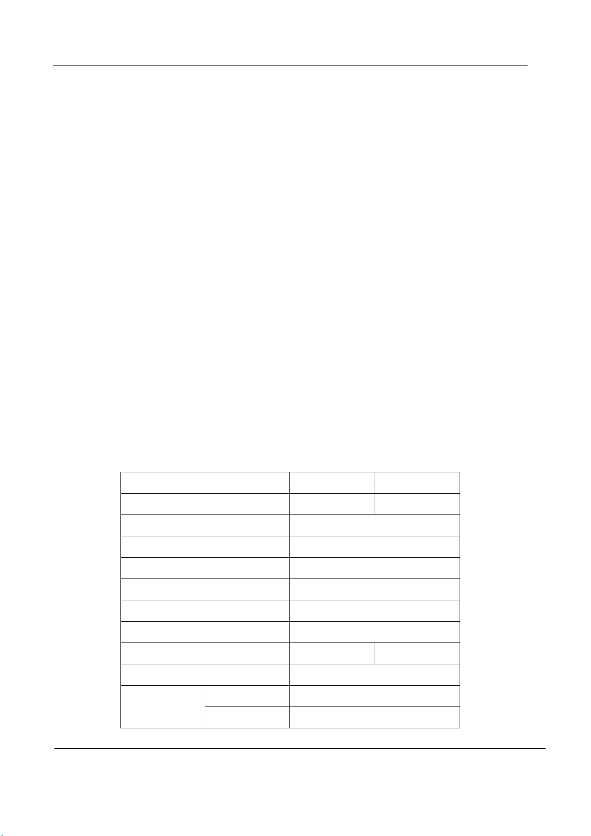
1. Lubrication
· When a new sewing machine is first operated, or when a sewing machine is operated which is out of
use for long period of time, it will be necessary to oil through the oil holes after removing the
rubber plugs shown below.
· See dripping of oil through the oil sight hole to check oiling condition during operation.
For oil, Use white spindle oil
2. Winding of bobbin thread
Note: When bobbin thread is wound, keep the presser foot lifted.
Adjustment:
·Tension of wound thread
Slack winding is recommended for polyester thread and nylon thread.
·Conically wound thread
Move the thread guide toward smaller diameter of wound thread layer.
·Length of wound thread
Loosen the thread length adjusting screw to increase length of thread and tighten the screw to
decrease length of thread.
— 2 —
3. Attaching the needle
Note: Before installing the needles, be sure to turn off the power.
4. Selection of thread
It is recommended to use “S” twist
thread in the left needle (viewed from front),
and “Z’ twist thread in the right needle.
When use of needle threads
discriminates is impossible, use “Z” twist
thread in both the needles.
For bobbin thread, “S” twist thread as
well as “Z” twist thread can be used.
— 3 —
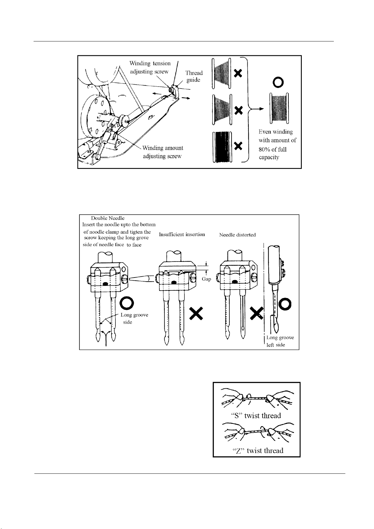
5. Threading of needle threads
1)Pass each needle thread through thread guide“A”.
Note: When thin slippery thread (polyester
thread or filament thread, for example)
is used pass the thread through thread
guides“B” as wall.
2)With the take-up lever located at the upper
most position, pass each needle thread in
the order shown in the following figure.
Note: Pressing the upper thread loosening button shown in the figure below opens the saucer of
the upper thread tension adjuster, and the upper thread can easily pulled out
6. Setting of bobbin
1)Pulling out 5. cm thread tail from
the bobbin.
2)Hold the bobbin so that the bobbin
thread is would in right direction
and put it into the hook.
— 4 —
7. Threading of bobbin threads
1)Put the hook into the bobbin case and press down the latch ①.
2)While holding the two needle threads by left hand, rotate the hand-wheel one turn by right hand.
By pulling up the needle threads, as shown in the figure, the bobbin threads will be lifted.
Each combination of bobbin thread and needle thread should be aligned and led backward.
8. Thread tension
1)Adjusting the bobbin thread tension
Turn tension screw, clockwise to increase the bobbin thread tension, or counter clockwise to
decrease it.
2)Adjusting the needle thread tension
· Needle thread tension should be adjusted in reference to bobbin thread tension.
· Turn tension nut clockwise to increase the needle thread tension, or counter clocking to decrease it.
· Needle thread tension can be also adjusted for special fabric and thread by changing intensity and
movable range of slack thread adjusting spring.
9. Thread take-upspring
1)To change the stroke of thread take-up spring
· Loosen screw“4”in the stopper, and
move stopper“3”to the right or left.
· Move the stopper to the right to
increase the stroke of the thread
take-up spring, or to the left to
decrease it.
— 5 —
2)To change the tension of the thread take-up spring
Loosen nut“2”and screw“5”.Turn spring shaft“1”counter clockwise to increase the tension
of the spring, or clockwise to decrease it. Fit a screwdriver in the spring shaft and turn it until the
desired tension is provided.
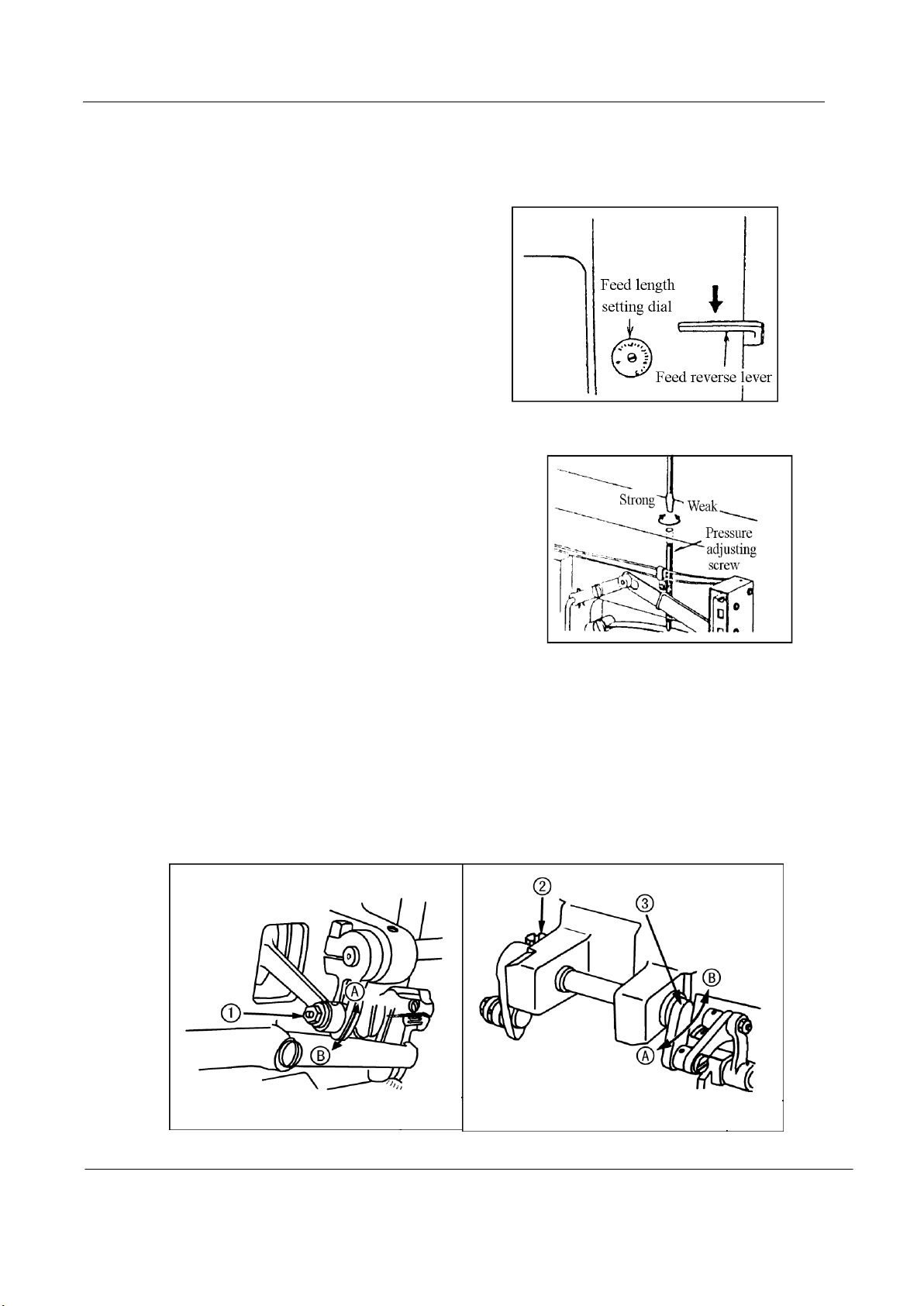
10. Adjusting the stitch length
Turn stitch length dial counter-clockwise
to bring the desired value to the top of the dial so
that the value is aligned with the pin.
Reverse feed stitching
1)The machine performs reverse feed stitching as
long as the lever is held depressed.
2)The moment you release the lever, the machine
resumed the normal stitching mode.
11. Adjusting the pressure of the presser foot
Pressure to fabric can be adjusted by turning the
pressure adjusting screw.
12. Adjusting the presser foot and the walking foot
1)Loosen not 1, and change the position of the cam
rod boss accordingly.
Highest position---The stroke is maximized. “A”
Lowest position--- The stroke is minimized. “B”。
2)Alternate vertical motions of the walking foot and presser foot
The alternate vertical strokes of the walking foot and presser foot
· Loosen screw ② of the top feed crank..
· Bring the thread take-up lever to its highest position, and lower the presser bar lifting lever. Move
top feed crank ③ to left“A”to increase the stroke of the presser foot, or to the right“B”to
increase it.
— 6 —
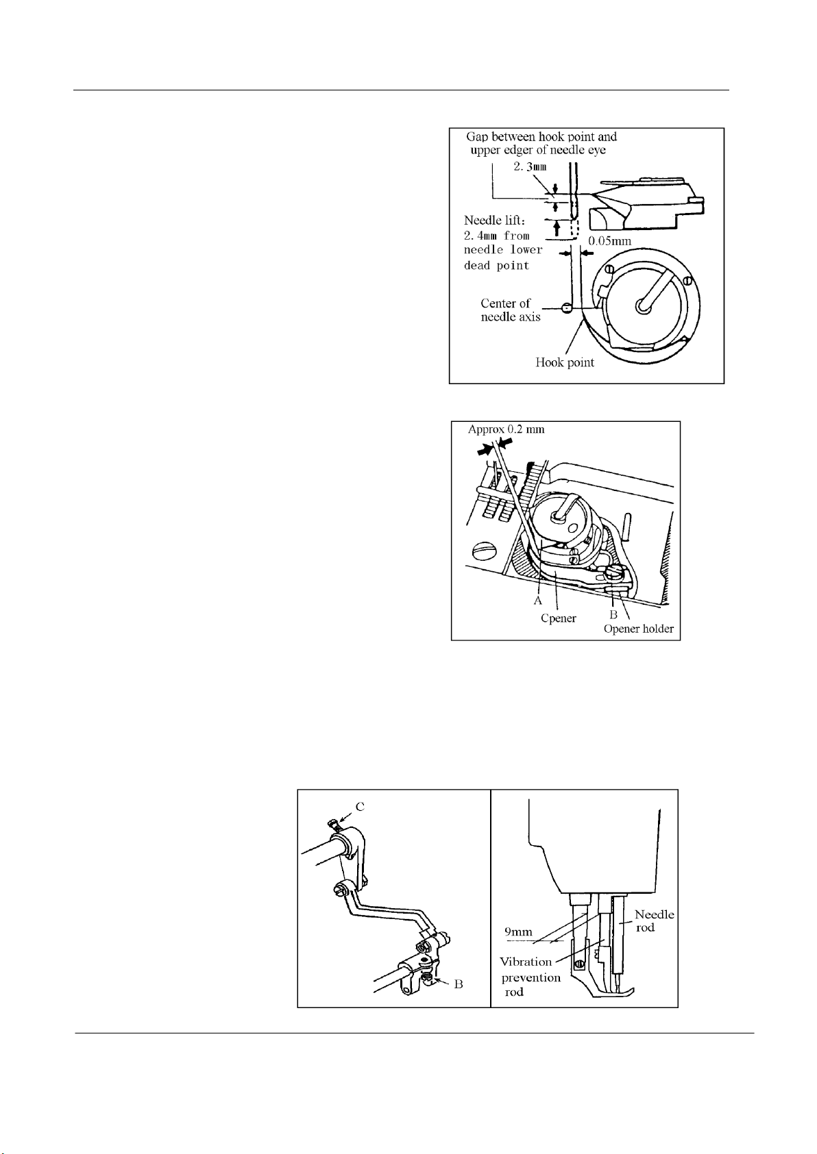
13. Timing between rotating hook motion and needle motion
1)Set feed length (stitch length) to “6” on the
feed setting dial.
2)When needle is lifted 2.4mm from the lower
dead point, as shown in Figure, the
following positional relationship should
be maintained.
· The upper edge of needle eye should be
2.3 mm below the hook point.
· The hook point should be located at the
center of needle axis.
· Gap between the hook point and the side
face of needle should be 0.0.5mm.
14. Relationship between hook motion and opener motion
1)Turn the balance wheel by hand and stop
when the opener holder is located most
remotely from the throat plate.
2) Make sure gap between the bobbin case
holder A and the opener is approximately
0.2 mm.
3) If the gap is too large or small , loosen the
opener holder set screw B and adjust
position of the opener.
15. Relationship between needle motion and feed dog motion
1)Set feed length to “0” on the feed setting dial
2) Set the needle at the lowest position.
3)Lean the machine head backward, remove the back cover, loosen screw B and C.
4)Adjust the distance between presser rod and vibration prevention rod to 9 mm.
5)After the completion of adjustment, fully tighten the screws B and C.
Note:
At this time make
certain that needle can
enter the feed dog needle
hole at the center of the
hole.
— 7 —
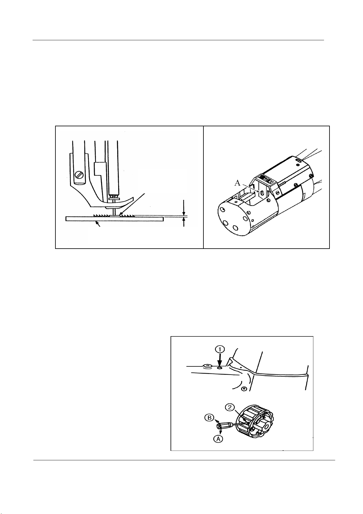
16. Adjusting the height of the feed dog
Feed dog
Needle plate 1 mm
The max. Height of the feed dog from the surface to the needle plate is normally 1mm.
To adjust this height:
1)Set the stitch length at minimum.
2)Turn the pulley so as to raise the feed dog to it highest position.
3)Loosen the screw“A”, adjust the height of the feed dog .
4)Tighten the screw“A”after adjustment.
17. Safety mechanism
If the thread is caught in the hook while the sewing machine is in operation, the safety
mechanism actuates to idle the lower sprocket only if the thread is caught in the hook while the
sewing machine is in operation, the safety mechanism actuates to idle the lower sprocket only.
1)How to reset
· Remove the thread caught6 in the hook
· Pressing push button ①, strongly
turn the pulley in the direction
opposite to its normal rotational
direction.
2)Safety load
Turn adjustment screw ② in
direction“A”(clockwise) to increase the
safety load, or in direction “ B ”
(counter-clockwise) to decrease it.
— 8 —
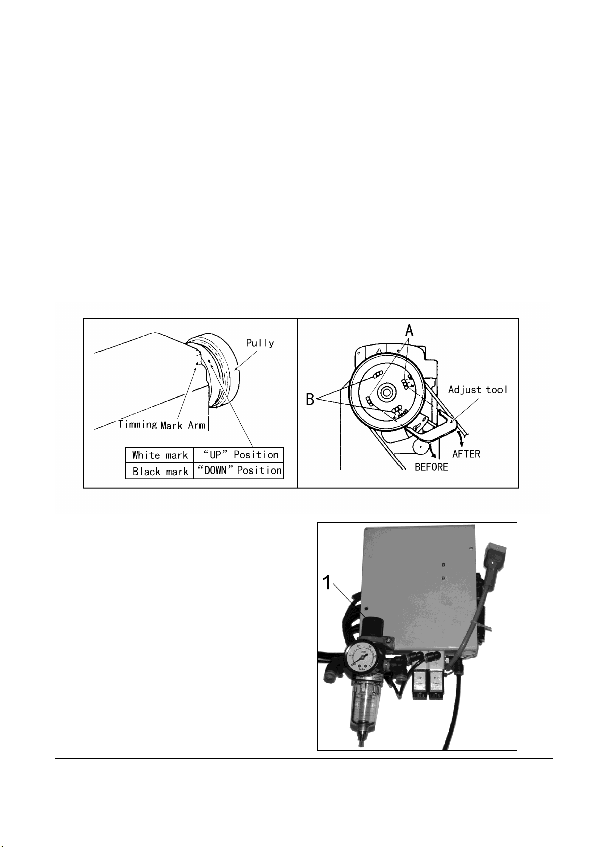
18. Adjustment of needle bar stop position (GC2268-2BL)
1)Adjust of “UP”position
When the pedal is kicked down by heel, the machine stops at “UP”position. If the marks
deviate larger than 3mm, adjust as follows.
· Disconnect the plug of cable from the machine head.
· Run the machine and stop at “UP”position.
· While holding the pulley, insert the “adjusting tool” in hole “A”, then remove the tool.
2)Adjust of “DOWN”position
When the pedal is “Neutral” the machine stops at “DOWN”position. If the marks deviate
larger than 5mm, adjust as follows.
· Disconnect the plug of cable from the machine head.
· Run the machine and stop at “DOWN”position.
· While holding the pulley, insert the “adjusting tool” in hole “B”, then remove the tool.
3)Confirm the stop operation, then set the plug coming from the machine head into the receptacle.
19. Regulate the atmospheric pressure
(GC2268-2BL)
When the air cylinder works normally, the
necessary atmospheric pressure is 5~6bar. Can
find out through the dial plate of the filtering.
1) Lifting knob 1, clockwise rotation, the pressure
increases.
2) Lifting knob 1, anticlockwise rotation, the
pressure is reduced.
— 9 —

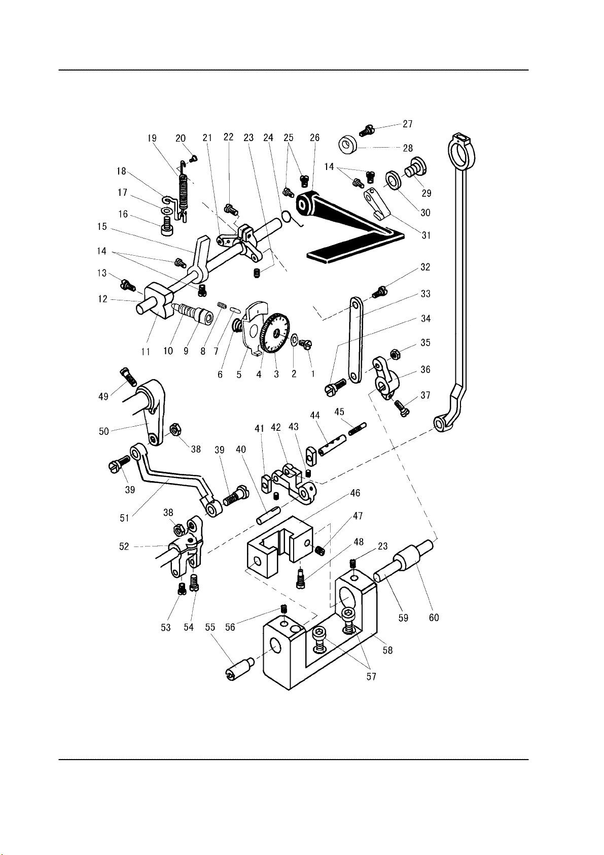
A. ARM BED AND ITS ACCESSORIES
7 8
\k!
3 4
2
56~
Lj~~~~~
9~~1
..
r;_..]
®~
G LW
~
22
23
~4
14
.
28
29
44
34
52
51~
50~'101
— 10 —
~~
49 48
45
46
47

A. ARM BED AND ITS ACCESSORIES
66
~6~li
54
93
92
91
90
— 11 —

A. ARM BED AND ITS ACCESSORIES
Pig.
No.
A01
A02
A03
A04
A05
A06
A07
A08
A09
A10
A11
A12
A13
A14
A15
A16
A17
A18
A19
A20
A21
A22
A23
A24
A25
A26
A27
A28
A29
A30
A31
A32
A33
A34
A35
A36
A37
A38
A39
A39
A40
A41
A42
Part No. Description
GC2268-2B
GC2268-2BL
HA300B2170 Face plat e s cr ew 9 9 SM11/64(40)×9
H4730B8001 Guide mounting plate 1 1
H4727B8001 Face plat e 1 1
HA300C2030 Screw 1 SM11/64(40)×8
H4731J8001 Holder 1
H4711J7101 Oil pipe 1
HH61B17101 Oil pipe 1 1
H411040160 Screw 2 2
HA100E2150 Screw 2 2 SM11/64(40)×10
H4722E8001 Washer 2 2
H4721E8001 Guide for slide block 1 1
H4716B8001 Oil guard plate 1 1
H4718B8001 Arm side cover 1 1
HA300B2170 Face plat e s cr ew 4 SM11/64(40)×9
H4719B8001 Arm side cover 1
H4717B8001 Thread take-up guard 1 1
HA300C2030 Screw 2 2 SM11/64(40)×8
H32175B304 Felt 1 1
H4715B8001 Oil cup 1 1 φ13
H4735B8001 Oil cup 1 2 φ22
HA700B2060 Screw 2 2 SM11/64(40)×8
H2400B2100 Thread guide 1 1
H7007D7101 Bobbin complete 1
H3107G0662 Screw 2
H6756B8001 Cut plate 1
HA500C2070 Screw
H7014D7101 Down-lead complete 1
H7016D8001 Washer 1
H6662B8001 Thread guide 1
HA300B2090 Oil cup 2 2 φ8.8
H2400B2060 Oil guard plate block 1 1
H3200B2060 Oil guard 1 1
H2400B2070 Thread guide 1 1
H2400B2080 Screw 2 2 SM3/16(28)×13
H4726B8001 Thread guide 1 1
H3000D2160 Screw 1 1 SM9/64(40)×6.5
H3212B0066 Thread guide 1 1
H3200B2100 Screw 1 1 SM9/64(40)×6.5
H4769E8001 Tension releasing pin 1
H7010E8001 Tension releasing pin 1
H4736B8001 Oil cup 1 1 φ15
HA307B0673 Oil cup 1 φ19
HA307B0673 Oil cup 1 1 φ19
2 SM9/64(28)×5
Remarks
— 12 —

A. ARM BED AND ITS ACCESSORIES
Pig.
No.
A43
A43
A44
A44
A45
A46
A47
A48
A49
A50
A51
A52
A53
A54
A55
A56
A57
A58
A59
A60
A61
A62
A63
A64
A65
A66
A67
A68
A69
A70
A71
A72
A73
A74
A75
A76
A77
A78
A79
A80
A81
A82
A83
Part No. Description
GC2268-2B
GC2268-2BL
HH60B68001 Arm 1
HH70B68001 Arm 1
HH60B78001 Arm bed 1
HH70B78001 Arm bed 1
HH60B98001 Felt 1
HH60B88001 Oil reservior 1
H4107B0672 Supporter 1
HE107I8001 Screw 1 M6
H4100B2090 Washer 1
H4100B2070 Screw 1 SM1/4(24)×9.8
H4100B2060 Link plate 1
H4100B2100 Hinge 1
H4100B2110 Hinge screw 6 SM1/4(24)×9.8
H3221B3142 Tension releasing plate 1 1
H3221B6811 Screw 2 2 SM9/64(40)×3
H3221B6812 Tension releasing spring 1 1
H4705C8001 Screw 1 1
H4706C8001 Lever 1 1
HA7311C306 Screw 1 1 SM9/64(40)×7
H4707C8001 Mounting plate 1 1
H007013050 Stop ring 1 1
H3221B6810 Nut 2 2
H4708C8001 Spring 1 1
H4709C8001 Push button 1 1
H3221B0681 Po rcelain cluct 2 2
H3221B0682 Pin 3 3
H3221B0685 Thread tension stud 1 1
H3221B0683 Thread tension stud 1 1
HA112B0693 Thread tension disc 4 4
H3221B0684 Spring 2 2
HA710B0671 Thumb nut 2 2 SM11/64(40)×6
H3221B0689 Thread tension stud 1 1
H3221B6816 Pin 1 1
HA310B0705 Thread tension disc 4 4
HA310B0702 Thread tension releasing disc 2 2
H4710C8001 Spring 2 2
HA115B7010 Thumb nut complete 2 2
HA310B0701 Thumb nut revolution stopper 2 2
H32481B721 Thumb nut 1 1 SM1/4(40)×4.5
H32481B621 Take-up spring guard 1 1
H32481BC21 Screw 1 1 SM9/64(40)×6
H32481BB21 Stopper 1 1
H32481B921 Thread tension post 1 1
Remarks
— 13 —

A. ARM BED AND ITS ACCESSORIES
Pig.
No.
A84
A85
A86
A87
A88
A89
A90
A91
A92
A93
A94
A95
A96
A97
A98
A99
A100
Part No. Description
GC2268-2B
GC2268-2BL
H32481B521 Screw 2 2 SM11/64(40)×10
H32481B821 Bush 1 1
H32481BF21 Plate complete 1 1
H4712C8001 Thread take-up spring 1 1
H32481BE21 Plate 1 1
H4713C8001 Thread take-up spring 1 1
H32481BD21 Plate complete 1 1
H32481B421 Screw 1 1
H3221B6820 Mounting plate 1 1
H3221B0686 Thread tension stud 1 1
H3221B6817 Pin 1 1
HA106B0676 Screw 1 1 SM9/64(40)×6
H3306B0661 Oil check window 1 1
H3221B6819 Stopper 1 1
H3200B2100 Screw 1 1 SM9/64(40)×6.5
H3230K0751 Screw 1 1 SM11/64(40)×10
H32481B121 Thread tension stud 1 1
Remarks
— 14 —
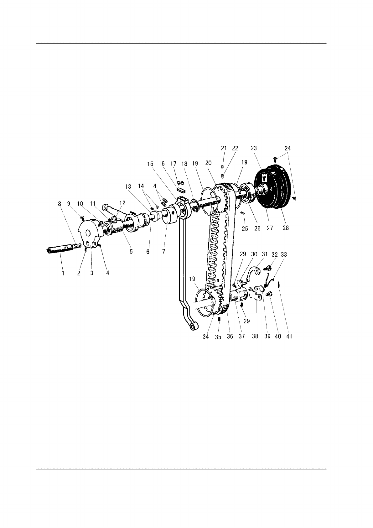
B. ARM SHAFT MECHANISM
23
13
2
29
24
— 15 —
37
38
39
40
41

B. ARM SHAFT MECHANISM
Pig.
No.
B01 H2405D0662 Hinge pin 1 1
B02 HA105D0662 Screw 1 1 SM1/4(40)×4
B03 H4706D8001 N eedle bar crank 1 1
B04 HA307C0662 Screw 3 3 SM1/4(40)×6
B05 H32111B204 Arm shaft bushing (left) 1 1
B06 HH61C08001 A rm shaf t 1
B06 HH70C58001 A rm shaf t 1
B07 H5332C8001 Feed cam (right) 1 1
B08 H4716F8001 Oil wick 1 1
B09 HA100C2060 Screw 1 1 SM9/32(28)×13
B10 HA100C2070 Screw 1 1 SM9/32(28)×14
B11 H2405D0664 Screw 1 1 SM15/64(28)×14
B12 H32111B104 Felt 1 1
B13 H7005D8001 Driving wheel 1
B14 H4723D8001 Screw 2 SM15/64(28)×4.5
B15 HH60C58001 Connecting rod for upper feed 1 1
B16 H20111C106 Holder 1 1
B17 H5330C8001 Felt 1 1
B18 H007009260 Stop ring 1 1
B19 H3205C0661 Spring stop ring 3 3
B20 HH60C78001 Pulley 1 1
B21 HE030C8001 Screw 1 1 SM17/64(24)×6.5
B22 HE029C8001 Screw 1 1 SM17/64(24)×14.5
B23 HA113F0684 Screw 2 SM15/64(28)×8.5
B24 HA110D0672 Screw 2 SM15/64(28)×12
B25 HE028C8001 Screw 1 1 SM17/64(24)×20
B26 H3205J0662 N eedle bearing 1
B27 H3205J0661 Arm shaft collar 1
B28 H4100C2040 B alance wheel 1
B29 HE022G8001 Screw 2 2 SM1/4(32)×10.5
B30 HE027G8001 Pin 1 1
B31 HE023G8001 Long lever for pulley 1 1
B32 HE024G8001 Pin 1 1
B33 HE026G8001 Spring for pulley 1 1
B34 HE019G8001 Pulley 1 1
B35 HE028E8001 Screw 2 2 SM7/32(32)×7
B36 HE109C8001 Cog belt 1 1
B37 HE021G8001 Shaft for pulley 1 1
B38 H4719D8001 Short lever for pulley 1 1
B39 HE031G8001 Lever for pulley 1 1
B40 HE029G8001 Pin 1 1
B41 H601012100 Pin 1 1
Part No. Description
GC2268-2B
GC2268-2BL
Remarks
— 16 —
C. NEEDLE BAR & THREAD TAKE-UP LEVER MECHANISM
9
6
— 17 —

C. NEEDLE BAR & THREAD TAKE-UP LEVER MECHANISM
Pig.
No.
C01 H4725F8001 Presser bar 1 1
C02 H3400C2020 Screw 1 1
C03 H3200I2030 Washer 1 1
C04 H3400C2010 N eedle bar guide 1 1
C05 H4726F8001 Presser bar connecting link 1 1
C06 H4729F8001 Spring 1 1
C07 H4753E8001 Screw 2 2 SM11/64(40)×17.5
C08 H4728F8001 Guide for slide block 1 1
C09 H4730F8001 V ibrating presser bar extension 1 1
C10 H2405D1122 Oil wick 2 2
C11 H4706F8001 Pin 1 1
C12 H4707F8001 Screw 1 1
C13 HA3411B308 Screw 1 1 SM15/64(28)×7
C14 H4719F8001 N eedle bar rock frame 1 1
C15 H4717F8001 N eedle bar connecting link 1 1
C16 H2405D1121 Pin 1 1
C17 H4712F8001 Th read take-up lever 1 1
C18 HA110D0672 Screw 1 1 SM15/64(28)×12
C19 H2405D1112 Thread take-up link 1 1
C20 H24211D405 Oil wick 1 1
C21 H24211D305 Oil wick 1 1
C22 H32111D304 Screw 6 6 SM3/32(56)×4
C23 H4721F8001 Washer 2 2
C24 H3204D6513 Felt 1 1
C25 H4722F8001 N eedle bar connecting stud 1
C26 H32111D604 Screw 1 1 SM9/64(40)×8.5
C27 H4724F8001 N eedle bar 1 1
C28 H3406C0672 Crank 1 1
C29 H4734F8001 Washer 1 1
C30 H3204B0652 Needle bar rock shaft bushing 2 2
C31 H4736F8001 N eedle bar rock shaft 1
C31 H7004F8001 N eedle bar rock shaft 1
C32 H602040240 Pin 1 1
C33 H3406C0671 Screw 1 1 SM15/64(28)×10
C34 H4759F8001 Square block 1 1
C35 H32132D104 Screw 2 2 SM9/64(40)×3
C36 H4739F8001 N eedle bar connecting stud 1 1
C37
C38 H4737F8001 V ibrating Presser foot 1 1
C39 HA700F2100 Screw 1 1 SM11/64(40)×7
Part No. Description
Needle 2 2 DP×17 23#
GC2268-2B
GC2268-2BL
1
Remarks
— 18 —
D. PREAAER FOOT MECHANISM
29
28~
27~~
25~'
"'
c
17~
...
a.
24~,
23-~
22---f/21
20-----
19~.
18/
17
p
(II"'
16/
15
30
1
0
l.
47
— 19 —

D. PREAAER FOOT MECHANISM
Pig.
No.
D01 H4705E8001 F eed lifting rock shaft 1 1
D02 H4706E8001 Screw 2 2 SM1/4(24)×7
D03 H4707E8001 Bushing 2 2
D04 H0030550608 Thumb nut 1 1 M6×0.75
D05 H3115F0671 Screw 1 1 SM1/4(28)×16
D06 H4709E8001 R egulating crank 1 1
D07 H2013J0065 Washer 1 1
D08 H2014J0066 Connecting rod 1 1
D09 H2000J2100 Screw 1 1 M6×0.75
D10 H20111C106 F elt clip 1 1
D11 H4713E8001 Oil wick 1 1
D12 HA307C0662 Screw 2 2 SM1/4(40)×6
D13 H007009250 Stop ring 1 1
D14 H4714E8001 Eccentric 1 1
D15 H4757E8001 Lifting Presser foot 1 1
D16 H3200E2020 Screw 1 1 SM1/8(44)×4
D17 H4708D8001 Screw 2 2 SM1/4(24)×13
D18 H4744E8001 Bushing for presser bar 2 2
D19 H4746E8001 Presser bar spring bracket 1 1
D20 H2404I0034 Screw 1 1 SM9/64(40)×8.5
D21 H4748E8001 Presser bar lifter 1 1
D22 H4749E8001 Screw 1 1 SM11/64(40)×8.5
D23 H4753E8001 Screw 1 1 SM11/64(40)×17.5
D24 H4717E8001 Roller 1 1
D25 H2004J0655 Support shaft 1 1
D26 H4718E8001 Screw 1 1 SM11/64(32)×6
D27 H2004J0662 Screw 1 1 SM1/4(40)×5
D28 H4719E8001 Link 1 1
D29 H4715E8001 B ell crank 1 1
D30 H4754E8001 Presser bar 1 1
D31 HA111G0683 Screw 2 2 SM11/64(40)×12
D32 H4723E8001 Guide 1 1
D33 H4752E8001 Presser bar lifting bracket 1 1
D34 H4768E8001 Th read releasing plate 1 1
D35 H4767E8001 Spring 1 1
D36 H4730E8001 Presser bar spring 1 1
D37 H4729E8001 Screw 1 1
D38 H3100G2170 Screw 1 1 SM1/4(24)×11
D39 H4725E8001 Screw 1 1 SM1/4(24)×19
D40 H4726E8001 Nut 1 1
D41 H3100G2130 Screw 1 1 SM1/4(24)×7
D42 H4727E8001 Spring 1 1
D43 HH60E48001 K nee lifter lever 1
Part No. Description
GC2268-2B
GC2268-2BL
Remarks
— 20 —

D. PREAAER FOOT MECHANISM
Pig.
No.
D43 H4728E8001 K nee lifter lever 1
D44 H2000I2140 Screw 1
D45 H2000I2150 Knee lifter lever joint 1
D46 H2000I2160 Nut 1 SM3/16(32)
D47 HH60E58001 K nee lifter rod 1
Part No. Description
GC2268-2B
GC2268-2BL
Remarks
— 21 —
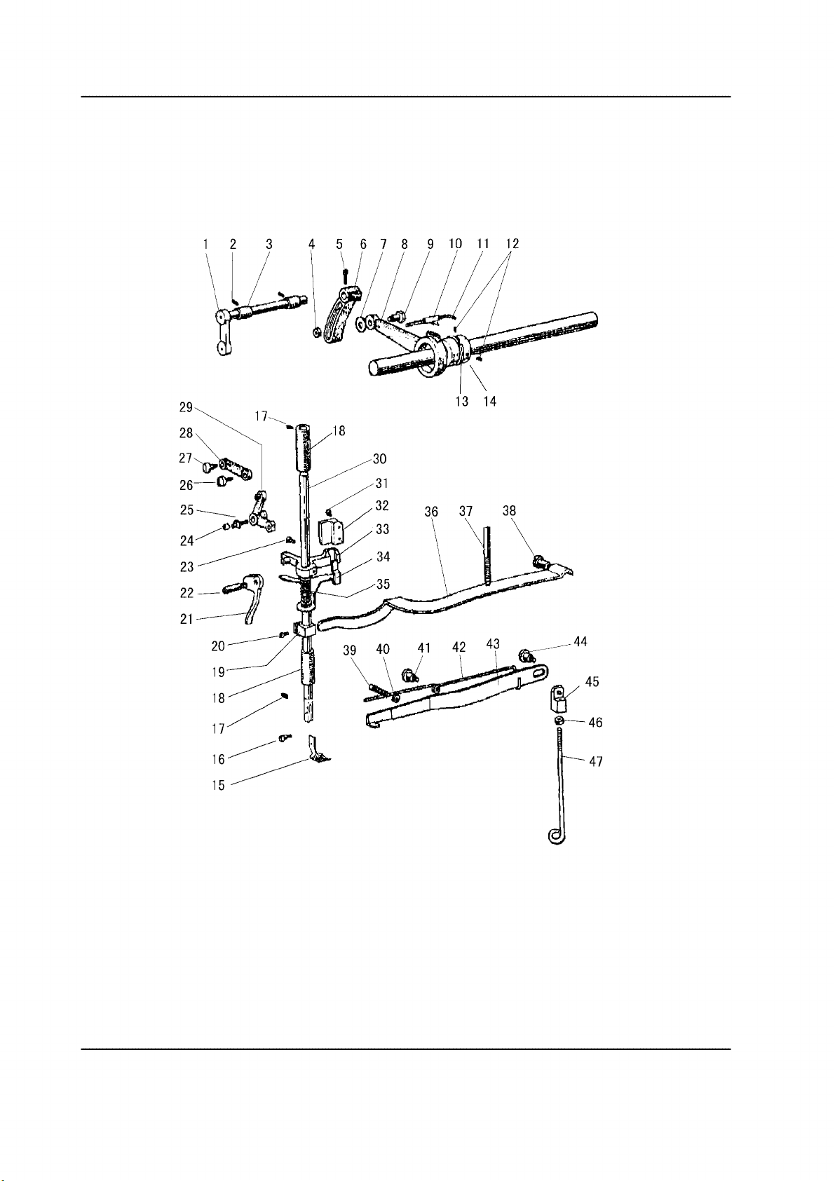
E. STITCH REGULATOR MECHANISM
22
18
17
1
15
6~~1
23
~27
®=------28
___
.J(
31
/32
~33
34
50
51
52
\
\
)
60
58
— 22 —

E. STITCH REGULATOR MECHANISM
Pig.
No.
E01 HA720F0686 Screw 1 1 SM3/16(28)×12
E02 HA720F0685 Bushing 1 1
E03 H5341H8001 Plate for stitch length 1 1
E04 HA7421F120 Dial 1 1
E05 HA720F0683 Stopper pin releasing lever 1 1
E06 HA720F0687 Co il sprin g 1 1
E07 HA700F2030 Stopper pin 1 1
E08 HA100F2090 Spring for stopper pin 1 1
E09 HA109F0674 Seal 1 1 14×2.4
E10 HA720F0681 Screw bar 1 1
E11 HH61F18001 Feed regulator crank 1 1
E12 HH61F28001 Feed reversing lever shaft 1
E12 HH70F88001 Feed reversing lever shaft 1
E13 HA104F0654 Screw 1 1 SM15/64(28)×10
E14 HA113F0684 Screw 4 SM15/64(28)×8.5
E15 HH71F08001 Baffle 1
E16 HA100H2150 Screw 1 1 SM9/64(40)×11
E17 H005004050 Washer 1 1
E18 H5330H8001 Spring retainer 1 1
E19 HG207G8001 Spring 1 1
E20 H5329H8001 Screw 1 1 SM9/64(40)×4
E21 H5327H8001 Feed reversing lever shaft crank 1 1
E22 H5343H8001 Screw 1 1 SM3/16(32)×16
E23 HA3411D308 Set screw 2 2 SM15/64(28)×7
E24 H4939L8001 Spring 1
E25 HA113F0684 Set screw 2 SM15/64(28)×8.5
E26 HH61F38001 Feed reversing lever 1
E26 HH70F98001 Feed reversing lever 1
E27 H4937L8001 Screw 1 SM15/64(28)×6
E28 H4938L8001 Rubber ring 1
E29 HA113F0683 Screw 1 SM3/16(28)×6.5
E30 HA100F2110 Washer 1
E31 H4936L8001 Lever 1
E32 H5333H8001 Screw 1 1 SM3/16(32)×8.5
E33 HH60F98001 Link lever 1 1
E34 H5324H8001 Screw 1 1 SM3/16(32)×13.5
E35 H5325H8001 Nut 1 1 SM3/16(32)×3.6
E36 H5322H8001 R ever se block shaft crank 1
E36 HH70F68001 R ever se block shaft crank 1
E37 HA104G0012 Screw 1 SM3/16(28)×12
E37 HA111G0683 Screw 1 SM11/64(28)×12
E38 H2010J0066 Nut 2 2 SM9/32(28)×3.6
E39 H5317H8001 Screw 2 2 SM9/32(28)×13.3
Part No. Description
GC2268-2B
GC2268-2BL
Remarks
— 23 —

E. STITCH REGULATOR MECHANISM
Pig.
No.
E40 H5315H8001 C rank shaft 1 1
E41 H5309H8001 S lid e block 2 2
E42 H5313H8001 Link lever 1 1
E43 HA711B0681 Screw 2 2 SM9/64(40)×4.5
E44 H5311H8001 Shaft for reversing block slide block 1 1
E45 H5312H8001 Oil wick 1 1
E46 H5305H8001 R ever se block 1
E48 HA100F2130 Screw
E47 HA300B2080 Set screw 1
E49 H5320H8001 Screw 1 1 SM15/64(28)×23.5
E50 HH60F78001 Link lever 1 1
E51 HH60F68001 Link lever 1 1
E52 H5314H8001 Crank 1 1
E53 HA700F2100 Screw 1 1 SM11/64(40)×7
E54 HA800F2020 Screw 1 1 SM15/64(28)×13.5
E55 H5308H8001 R ever se block shaft 1
E55 HH70F48001 R ever se block shaft 1
E56 HA100C2020 Set screw 1 1 SM15/64(28)×10
E57 H415060160 Screw
E58 HH60F48001 Mounting frame 1
E59 H5306H8001 R ever se block shaft
E60 H5307H8001 Bushing for reverse block shaft 1 1
Part No. Description
GC2268-2B
1
1 1
1
2
1 1
Remarks
GC2268-2BL
SM15/64(28)×5
SM15/64(28)×6.5
— 24 —

F. FEEDING AND FEED LIFTING & ROTATING HOOK SHAFT MECHANISM
15
10
9
8
7
1~~4
/
/ /
(j / (
\
)
/
/
/
'6''
lY
t:16
~::
y19
I
I
I
I
I
I
I
v
— 25 —

F. FEEDING AND FEED LIFTING & ROTATING HOOK SHAFT MECHANISM
Pig.
No.
F01 HE114E8001 Screw 1 1 SM11/64(40)×6
F02 HE115E8001 Washer 1 1
F03 HE012E8001 Connecting screw for feed dog 1 1 SM11/64(32)×6.5
F04 HE112E8001 Feed dog 1 1
F05 HE113E8001 Feed rock lifting shaft cran k 1 1
F06 H41111E204 Felt 1 1
F07 HE117E8001 Oil wick 1 1
F08 HE116E8001 Pin 1 1
F09 HE046C8001 Screw 2 2 SM0.1339(36)×6
F10 HE105E8001 Slide block for crank 1 1
F11 HE109E8001 Screw 1 1 SM9/64(40)×5
F12 HE110E8001 Roller 1 1
F13 HE108E8001 Screw 2 2 SM9/64(40)×7
F14 HE106E7101 Mounting frame 1 1
F15 HE104E8001 Feed rock shaft crank 1 1
F16 HE109D8001 Safe clutch shaft 1 1
F17 H4107D0672 Safe clutch spring 1 1
F18 HE108D8001 Safe clutch bushing 1 1
F19 H601016100 Safe clutch shaft pin 1 1
F20 HE110D8001 B evel gear for hook shaft 2 2
F21 HG214G8001 Set screw 6 6 SM1/4(40)
F22 HE105C8001 Set screw 1 1 SM13/64(32)×4.7
F23 HE111D8001 Rotating hook shaft bushing (left) 1 1
F24 HE112D8001 Felt 1 1
F25 HE106D8001 R eces s ed wheel 1 1
F26 HE043C8001 Set screw 1 1 SM1/4(28)×6.5
F27 HE013H8001 Screw 3 3 SM13/64(32)×4.3
F28 HE113D8001 Bushing 1
F28 HH70G58001 Bushing 1
F29 HE104D8001 Rotating hook shaft 1
F29 HH70G48001 Rotating hook shaft 1
F30 HE104C8001 Feed eccentric 1 1
F31 HE121E8001 Set screw 2 2 SM13/64(32)×5
F32 HE013C8001 Screw 1 1 SM17/64(24)×6.5
F33 H4100D2100 Bushing 2
F34 HE034G8001 Screw 2 4 SM1/4(32)×7
F35 HE107D8001 Screw 1 1 SM1/4(28)×6
F36 HE105D8001 Rotating hook shaft collar 2 2
F37 HE119E8001 Screw 1 1 SM5/32(40)×9
F38 HE118E7101 Feed rock shaft 1
F38 HH70G67101 Feed rock shaft 1
F39 HE113D8001 Bushing 1
F39 H5321E8001 Bushing 1
Part No. Description
GC2268-2B
GC2268-2BL
Remarks
— 26 —

G. HOOK SADDLE MECHANISM
22
31
32
33
34
35
— 27 —

G. HOOK SADDLE MECHANISM
Pig.
No.
G01 HD806I8001 Bobbin 2 2
G02 HH60H67101 Rotating hook 2 2
G03 HE117B8001 Rotating position guide 2 2
G04 HE046C8001 Screw 2 2 SM0.1339(36)×6
G05 HE116B8001 Guide plate slide block 2 2
G06 HE121B8001 Washer 4 4
G07 HE120B8001 Washer 4 4 SM13/64(32)×16.5
G08 HE125B8001 Bushing 2 2
G09 HE124B8001 Washer 2 2
G10 H2404I0652 Screw 2 2 SM9/64(40)
G11 HE127B7101 Guide plate 2 2
G12 HE126B8001 Felt 2 2
G13 HE147B8001 Rotating hook bracket 1 1
G14 HE119B8001 Rotating hook bracket 1 1
G15 HE028E8001 Screw 2 2 SM7/32(32)×7
G16 HE123B8001 Bevel 2 2
G17 HE143B8001 Screw 2 2 SM13/64(32)
G18 H005009050 Washer 2 2
G19 HE113B8001 Connecting frame 1 1
G20 HE131B8001 F ro n t guid e plate (left) 1 1
G21 HE130B8001 Screw 8 8 SM0.1339(36)×8.2
G22 HE144B8001 Connecting plate 2 2
G23 HE145B8001 Screw 10 10 SM11/64(40)×9
G24 HE133B7101 F ro n t slid e plate 1 1
G25 HE137B8001 Set screw 2 2 SM11/64(32)×10
G26 HE136B8001 N eedle plate 1 1
G27 HE140B8001 B ack guide plate (left) 1 1
G28 HE138B7101 B ack slide plate 1 1
G29 HE142B8001 Connecting plate 2 2
G30 HE141B8001 B ack guide plate (right) 1 1
G31 HE115B8001 S lid e plate 1 1
G32 H4111E0682 B ack guide plate (left) 1 1
G33 HE114B8001 N eedle plate 1 1 M4×4
G34 HE132B8001 F ro n t guid e plate(right) 1 1
G35 HE146B8001 S lid e plate 1 1
Part No. Description
GC2268-2B
GC2268-2BL
Remarks
— 28 —

H. PNEUMATIC CONTROL UNIT
7
6
5
4
3
2
~
~
'""
-,""'
8
9
~
'
l
~
'"'-..
,___.-
'
10
1)1
~
~
b\,----
--
23
24
6
22
11
21
18
14
17
28 29
30
31
— 29 —
32 33
34 35
36
37

H. PNEUMATIC CONTROL UNIT
Pig.
No.
H01 HA300B2130 Screw
H02 H0606N8001 Support block
H03 H005008060 Spring Washer
H04 H415060200 Screw
H05 H0605N8001 F ixing plate
H06 H4916G8001 Windpipe joint
H07 H0608N8001 Wire joint
H08 H415050450 Screw
H09 H0607N8001 Pump
H10 HA300B2170 Screw 2 SM11/64(40)×9
H11 HA700Q0050 Holder
H12 H4915G8001 Pump 1 SDA25×25-B
H13 HA300B2170 Screw 4 SM11/64(40)×9
H14 HH70I58001 Arm side cover 1
H15 H005008060 Spring Washer 4
H16 H415060200 Screw 4
H17 H4913G8001 Coupling 1
H18 H4914G8001
H19 HD44JM8001 Holder
H20 HA100I2090 Screw
H21 HA708P0668 Holder
H22 H4980K8001 Holder
H23 H4918L8001 Screw
H24 HH70I57101 Touth switch complete
H25 HA703R0065 D etector bracket (complele)
H26 HA703R0067 Washer
H27 HA300C2030 Screw
H28 H3205J0662 N eedle bearing
H29 H007009300 Retaining ring C-type
H30 HA700R0060 Washer
H31 HA700R0050 Support spring
H32 HA700R0040 Spacer B
H33 H4928L8001 Speed command disk F20 (up)
H34 HA700R0030 Spacer A
H35 H4930L8001 Speed command disk F11 (down)
H36 HA110D0672 Screw
H37 H4931L8001 Pulley (complele)
Part No. Description
Link 1
GC2268-2B
GC2268-2BL
3
1
2
2
1
3 φ6-M5
1 φ6-M5
4
1 SDA25×25-B
3
1
1
1
3
2
1
1
1
1
1
1
1
1
1
1
2
1
2
1
Remarks
SM11/64(40)×5.5
SM11/64(40)×13
SM11/64(40)×8
NTN 6204Z
SM15/64(28)×12
— 30 —
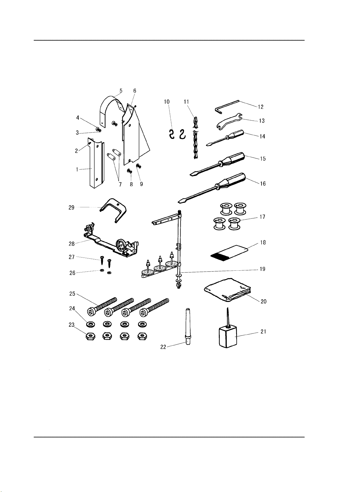
I. ACCESSORIES
5 6
~12
~13
~14
15
16
22
— 31 —
20
21

I. ACCESSORIES
Pig.
No.
I01 HH60I68001 B elt cover (left) 1
I01 HH70J68001 B elt cover (left) 1
I02 H2000O0360 Screw 2 2 SM11/64(40)×6
I03 H0207L8001 Screw 2 2 SM15/64(28)×18
I04 H6760B8001 Washer 2 2
I05 H6307L8001 B elt cover (upper) 1 1
I06 HH60I78001 Belt co ver (right) 1
I06 HH70J78001 Belt co ver (right) 1
I07 HH60I88001 Screw 2 SM15/64(28)
I08 HN720J8001 Screw 2 SM15/64(28)×10
I08 H0207L8001 Screw 2 SM15/64(28)×18
I09 H005006060 Washer 2
I10 H8000H2070 Pothook 2
I11 HPG100E203 Chain 1
I12 HB00001060 Sockt wrench 1 1
I13 HE105I8001 Spanner 1 1
I14 HA300J2210 Screw driver (small) 1 1
I15 HA300J2200 Screw driver (middle) 1 1
I16 HA300J2070 S crew driver (larger) 1 1
I17 HD806I8001 Bobbin 4 4
I18
I19 H3200L0120 Th read stand assay 1 1
I20 HA100J2180 Cover 1
I20 H7009K8001 Cover 1
I21 H2004O0069 Oil tank 1 1
I22 H6620J8001 H ead rest bar 1
I23 H003002080 Nut 4
I23 H003002120 Nut 4
I24 H005001080 Washer 4
I24 H005001120 Washer 4
I25 H403080750 Screw 4
I25 H103120120 Screw 4
I26 HA300J2230 Washer 2
I27 H801045200 Wood screw 2
I28 H3300L0040 Bobbin winder assay 1
I29 HA704S0654 Adjusting plate for speed command disk 1
Part No. Description
Needle 6 6 DP×17 23#
GC2268-2B
GC2268-2BL
Remarks
— 32 —
GAUGE PARTS LIST
Description
Part No.
1/4"(6.4mm) 1/8"(3.2mm) 3/8"(9.5mm) 1/2"(12.7mm)
Vibrating Presser foot
Needle Clamp
Lifting Presser foot
Feed Dog
Needle Plate
Front Slide Plate
Back Slide Plate
Front Guide Plate (left)
Front Duide Plate (right)
Back Duide Plate (left)
Back Duide Plate (right)
H4737F8001 H4741F8001 H4745F8001 H4746F8001
H4739F8001 H4750F8001 H4754F8001 H4755F8001
H4757E8001 H4758E8001 H4762E8001 H4763E8001
HE112E8001 HE139E8001 HE138E8001 HH60G48001
HE136B8001 HE169B8001 HE160B8001 HH61H18001
HE133B7101 HE165B7101 HE156B7101 HH60H97101
HE138B7101 HE167B7101 HE158B7101 HH61H07101
HE131B8001 HE161B8001 HE152B8001 HH61H28001
HE132B8001 HE162B8001 HE153B8001 HH61H38001
HE140B8001 HE163B8001 HE154B8001 HH61H48001
HE141B8001 HE164B8001 HE155B8001 HH61H58001
— 33 —

SHANGHAI HUIGONG NO.3 SEWING MACHINE FACTORY
ADD: 1418, Yishan Road, Shanghai, China
Zip Code: 201103
Overseas Business: TEL: 86-21-64853303 FAX: 86-21-64854304
E-mail:highlead@online.sh.cn http://www.highlead.com.cn
The description covered in this manual is subje ct to change for improvement of the commodity without notice
2008.12. Printed
 Loading...