

Page 1
HIGH
GC2268
LEAD
CYLINDER-BED UNISON
Instruction
Parts Catalog
FEED
Manual
SEWING
MACHINE
SHANGHAI HUIGONG
N0.3
SEWING MACHINE FACTORY
Page 2
PRECAUTIONS
1. Safety precautions
1)
When turning the power on, keep your hands and fingers away from the area around/under the needle
and the area around the pulley.
2)
Power must
Power must be turned off when tilting the machine head, installing or removing the ''V" belt, adjusting
3)
the machine, or when replacing.
4)
Avoid placing fingers, hairs, bars etc., near the pulley, "V" belt, bobbin winder pulley, or motor
be
BEFORE
turned off when the machine
STARTING OPERATION
is
not
in
use,
or
when the operator leaves the seat.
when
the machine
5)
Do
not insert fingers into the thread take-up cover, under/around the needle, or pulley
machine
2.
Precautions before
1)
Do
not operate the machine before lubricating
2)
When a new sewing machine
power on (the pulley should rotate counterclockwise when viewed from pulley) .
3)
Verify
3.
Precautions
1)
Avoid
or lower)
2)
Avoid
is
in
operation.
is
in
operation.
starting
the voltage and
for
operating
using the machine at abnormally high temperatures (
using the machine
operation
is
(s·ingle
or three) phase with those given on the machine nameplate.
conditions
in
dusty conditions.
first turned on, verify the rotational direction
CAUTIONS ON USE:
1.
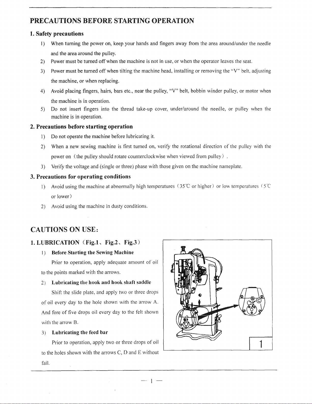
LUBRICATION CFig.L Fig.2, Fig.3)
it.
35
"C
or higher) or
of
the
pulley
low
temperatures ( 5
when
with
the
the
"C
1)
Before
Prior to operation, apply adequate amount
to
the points marked with the arrows.
2)
Lubricating
Shift the slide plate, and apply two or three drops
of
oil
And
fore
with
the
3)
Lubricating
Prior
to
the
fail.
Starting
every day
of
five drops
arrow
to
operation, apply two or three drops
holes shown with the arrows
the
Sewing Machine
the
hook
and
hook
to
the hole shown with the arrow
oil
every day
B.
the
feed
bar
shaft
to
the felt shown
C,
D and E without
of
saddle
of
-1-
oil
A.
oil
Page 3
2
3
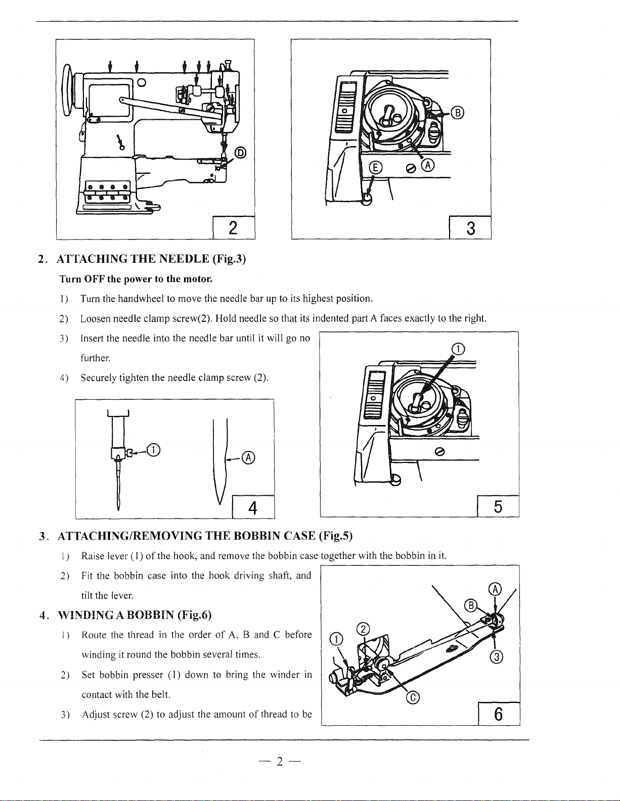
2. ATTACHING
Turn
OFF
I)
Turn the
2) Loosen needle
3) Insert the needle into the needle
further.
4)
Securely tighten
THE
NEEDLE
the power to the motor.
handwheel
clamp
the
to
needle
CD
3.
ATTACHING/REMOVING
(Fig.3)
move
the needle bar up to its highest position.
screw(2). Hold needle so that its indented part A faces exactly to the right.
bar
clamp
until it will
screw (2).
go
no
-®
4
THE
BOBBIN CASE (Fig.5)
5
I) Raise lever
2) Fit the bobbin
tilt the lever.
(I)
of
the
hook, and remove the bobbin case
case
into
the
hook
driving shaft, and
together
with the bobbin in
4. WINDING A BOBBIN (Fig.6)
I) Route the thread in the
it
winding
2) Set bobbin
contact with
3) Adjust screw (2) to
round the bobbin several times.
presser
the
belt.
(I)
down
adjust
order
the
of
A, 8 and C before
to bring
amount
the
winder
of
thread to be
in
-2-
it.
6
Page 4
would round the bobbin so that the bobbin
is
wound with
thread
about
80%
of
its capacity. Turn the
screw clockwise to increase the amount
If
4)
5) The moment the bobbin has been wound up, the bobbin presser is released, and the bobbin winder will
5,
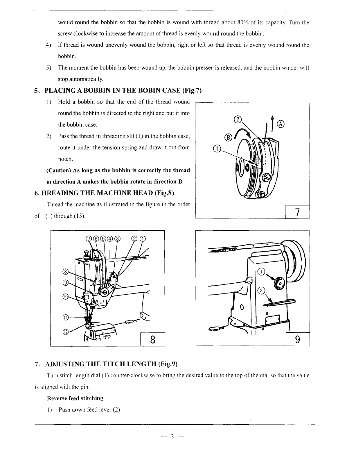
PLACING A BOBBIN IN
2) Pass the thread in threading slit (1) in the bobbin case,
(Caution) As long as
6.
HREADING
thread is
bobbin.
stop automatically.
1)
Hold a bobbin so that the end
round the bobbin is directed to the right and put
the bobbin case.
route it under the tension spring and draw
notch.
in
direction A makes
wound
unevenly wound the bobbin, right or left
THE
the
bobbin
t,he
bobbin rotate in direction
THE
MACHINE HEAD (Fig.8)
is
BOBIN CASE (Fig.7)
of
correctly the
of
thread
is
evenly
the thread wound
it
into
it
out from
thread
B.
wound
so
that thread
round the bobbin.
is
evenly wound round the
Thread the machine as illustrated
of
(1)through(13).
G)@@®@
@
®
@
7. ADJUSTING
THE
TITCH
in
the figure
in
the order
8
LENGTH (Fig.9)
;p
7
AD-=
9
Turn stitch length dial (
is
aligned with the pin.
Reverse feed stitching
I) Push down feed lever (2)
1)
counter-clockwise to bring the desired value to the top
3
of
the dial so that the value
Page 5
2) The machine performs reverse feed stitching as long as the lever
3) The moment you release the lever, the machine resumed the normal stitching mode.
8.
THREAD TENSION
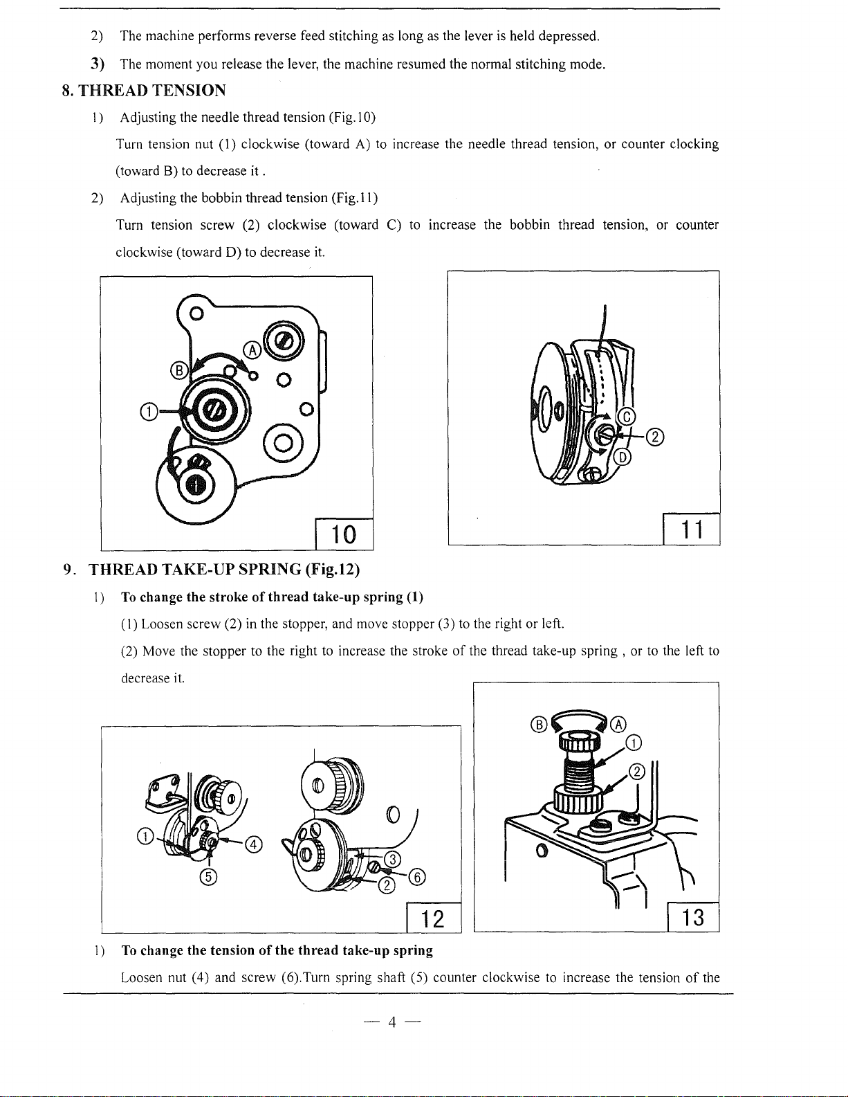
1)
Adjusting the needle thread tension (Fig. I 0)
is
held depressed.
Turn tension nut
(toward B) to decrease
2) Adjusting the bobbin thread tension (Fig.
Turn tension screw (2) clockwise (toward C) to increase the bobbin thread tension, or counter
clockwise (toward D) to decrease
(I)
clockwise (toward A) to increase the needle thread tension, or counter clocking
it.
II)
it.
10
1 1
9. THREAD TAKE-UP SPRING (Fig.12)
1)
To
change the stroke
(I)
Loosen screw (2) in the stopper, and move stopper (3) to the right or left.
(2) Move the stopper to the right to increase the stroke
decrease
it.
of
thread
take-up spring (1)
®
'------------'-------'1
1)
To
change the tension
of
the
thread
take-up
spring
of
the thread take-up spring , or to the left to
I I
I I
II
L---1
_
____,__
Loosen nut (4) and screw (6).Turn spring shaft (5) counter clockwise to increase the tension
-4-
of
the
Page 6
spring,
tension is provided.
10.
ADJUSTING
or
clockwise to decrease
THE
PRESSURE
it
. Fit a screwdriver
OF
THE PRESSER
in
the
FOOT
spring
(Fig.13)
shaft and turn
it
until the desired
I) Turn pressure spring
co\.)nter clockwise (toward B) to decrease
2) After the adjustment, securely tighten nut (2)
11.
ADJUSTING
I) Loosen not
Highest position---The stroke
Lowest position--- The stroke
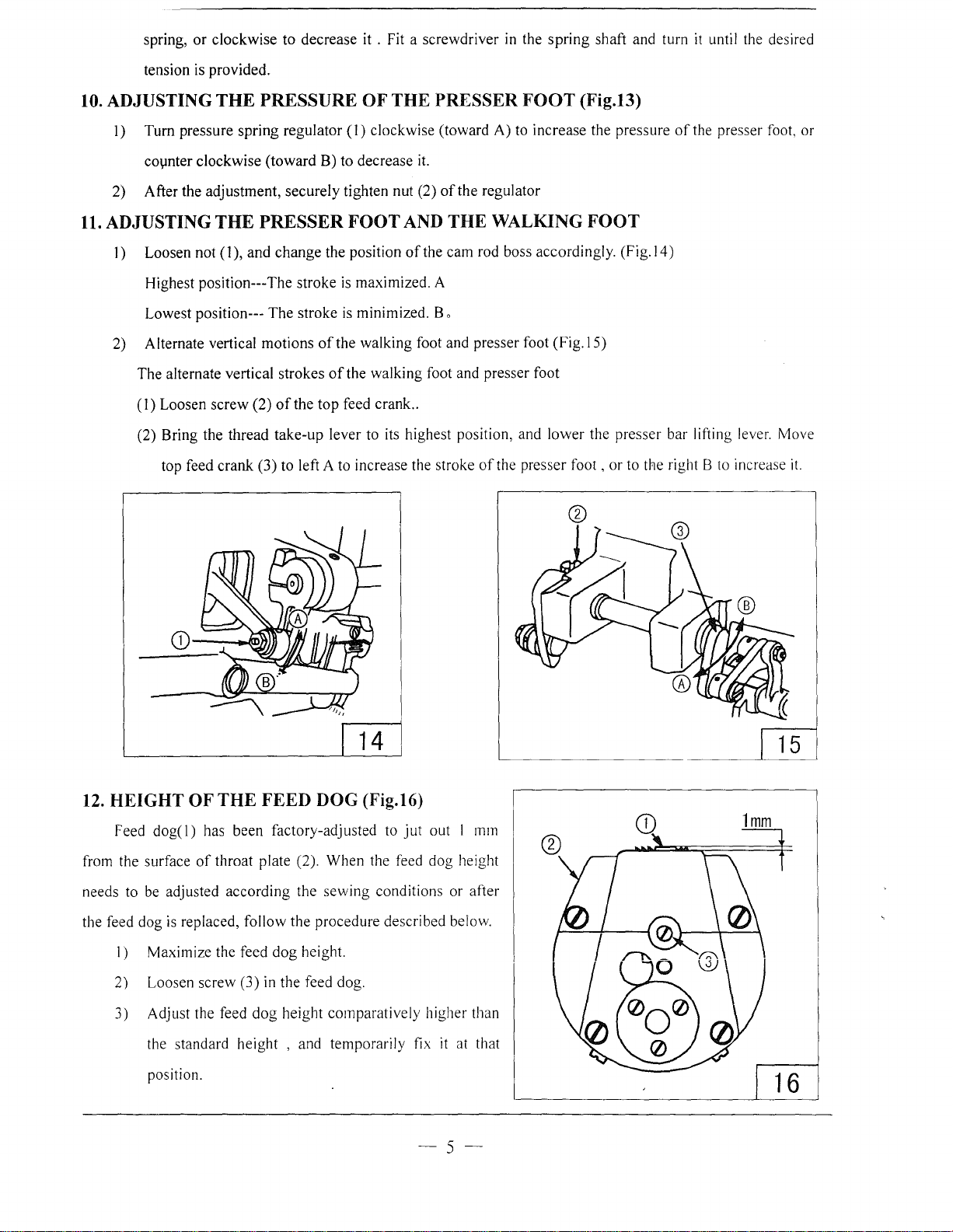
2) Alternate vertical motions
The alternate vertical strokes
(1) Loosen screw (2)
(2) Bring the thread take-up lever to its highest position, and lower the presser bar lifting lever. Move
top feed crank (3) to left A to increase the stroke
THE
(1
), and change the position
regulator(!)
PRESSER FOOT
is
maximized. A
is
minimized. B o
of
the walking foot and presser foot (Fig.15)
of
the walking foot and presser foot
of
the
top
feed crank
clockwise (toward A) to increase the pressure
it.
of
the regulator
AND
THE WALKING
of
the cam rod boss accordingly.
..
of
the presser
FOOT
(Fig.l4)
foot,
or to the right B to increase
of
the presser foot, or
it.
14
12.
HEIGHT OF
Feed
dog(!)
from the surface
needs to be adjusted according the sewing conditions or after
the feed dog
I) Maximize the feed
2) Loosen screw (3)
3) Adjust the feed
is
the standard height , and temporarily fix
position.
THE
FEED DOG (Fig.16)
has been factory-adjusted to
of
throat plate (2). When the feed dog height
replaced, follow the procedure described below.
dog
height.
in
the feed dog.
dog
height comparatively higher than
jut
out I mm
it
at that
-5-
Page 7
4) Now, adjust the height
dog.o
of
the feed
dog
appropriately, and securely tighten the screw (3)
in
the feed
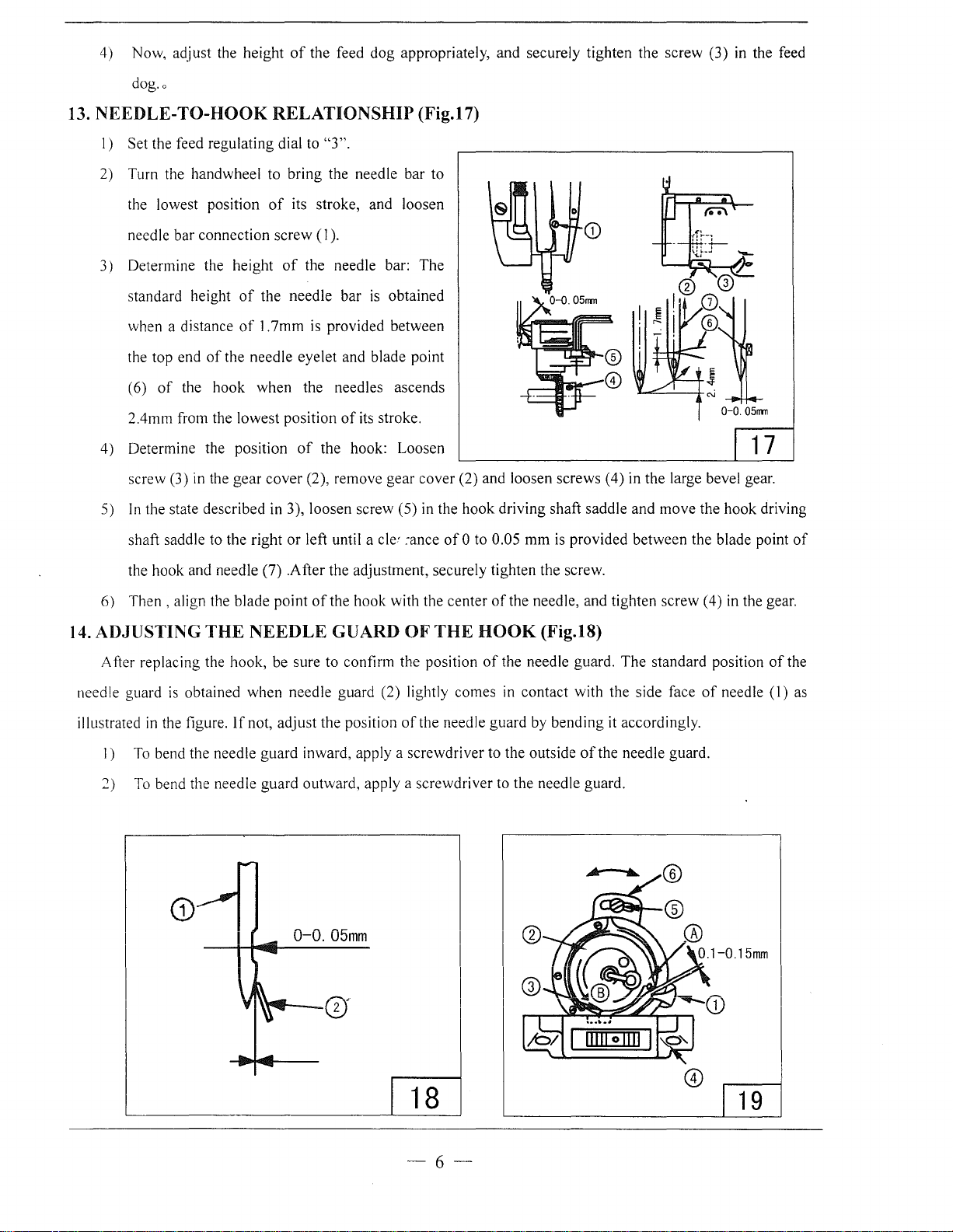
13. NEEDLE-
I)
Set the feed regulating dial to
2) Turn the handwheel to bring the needle bar to
the lowest position
needle bar connection
3) Determine the height
standard height
when a distance
the top end
(6)
2.4mm from the lowest position
4) Determine the position
screw (3) in the
In
5)
shaft saddle to the right
TO-HOOK
of
the needle eyelet and blade point
of
the hook
the state described in 3), loosen screw (5) in the
RELATIONSHIP (Fig.17)
"3".
of
its stroke, and loosen
screw
(I).
of
the needle bar:
of
the needle bar
of
1.7mm is provided between
when
gear
the needles ascends
of
the hook: Loosen 1 7
cover
(2), remove gear cover (2) and loosen screws (4) in the large bevel gear.
or
left until a
is
of
its stroke.
The
obtained
cle~
:ance
hook
of
0 to 0.05
driving shaft saddle
mm
is provided between the blade point
and
move
0-0.0511T11
the
hook
driving
of
the hook and needle (7) .After the adjustment, securely tighten the screw.
Then,
6)
14. ADJUSTING
After replacing the hook, be sure to confirm the position
needle guard
illustrated
I)
2)
align the blade point
THE
NEEDLE
is
obtained when needle guard (2) lightly comes in contact with the side face
in
the figure.
To bend the needle guard inward, apply a screwdriver to the outside
To
bend the needle guard outward, apply a screwdriver to the needle guard.
If
not, adjust the position
of
0-0.
the
hook
GUARD
05mm
with the center
OF
of
of
the needle, and tighten screw (4) in the gear.
THE
HOOK
of
the needle guard.
the needle guard by
(Fig.18)
bending
of
The
standard position
it accordingly.
the needle guard.
of
needle
of
(I)
the
as
18
-6-
19
Page 8
15. ADJUSTING
I)
Tum
the hand wheel in its
end position.
Tum
2)
bobbin case (2) in
throat plate ( 4 ).
THE
BOBBIN CASE OPENNING
nonnal
the
rotational direction to bring
direction
of
arrow
B until stopper
LEVER
bobbin
(3)
(Fig.19)
case
opening
comes in contact with the groove
lever (1) to its back
in
3) Loosen screw (5) in the bobbin case
of
THE
0.1 to 0.15
LONGITUDINAL POSITION
that a clearance
16. ADJUSTING
opening
mm
is
protruding section A
lever adjustment plate (6) in
(Fig.20)
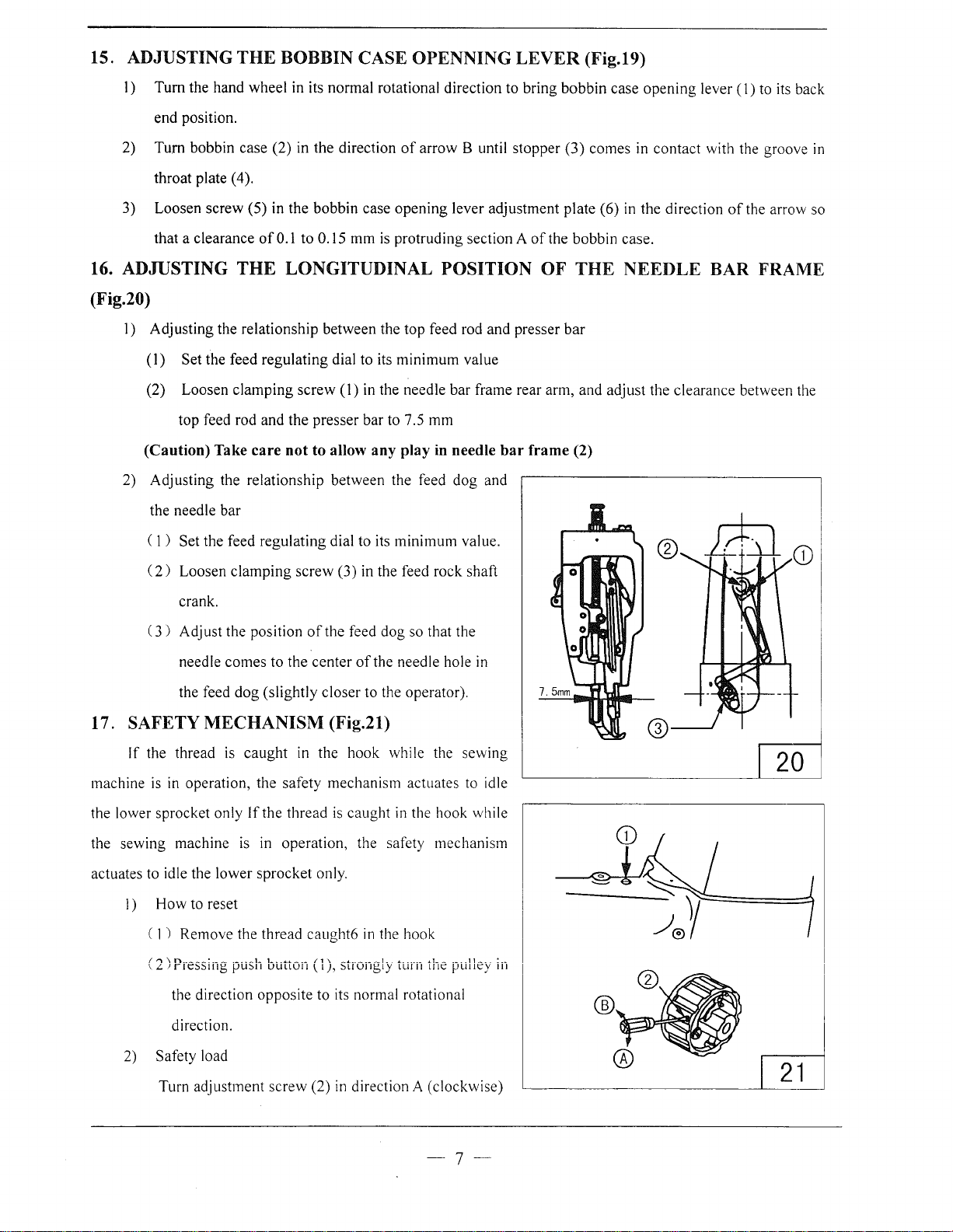
I) Adjusting the relationship between the top feed rod and presser
(I)
Set the feed regulating dial to its
(2) Loosen
top feed rod and
(Caution) Take
2) Adjusting the relationship between the feed
the needle bar
(I)
Set the feed regulating dial to its minimum value.
(
2)
Loosen
crank.
(3)
Adjust the position
clamping
care
clamping
screw
(I)
the
presser
not
to allow any play
screw
(3) in the feed rock shaft
of
the feed
minimum
in the needle
bar
to 7.5 mm
in
dog
so that the
value
bar
frame rear arm, and adjust the clearance between the
needle
dog
and
bar
of
the bobbin case.
OF
THE
bar
frame (2)
the
direction
of
the arrow so
NEEDLE BAR FRAME
comes
to
the
center
of
needle
the feed
dog
(slightly closer to the operator).
the needle hole
17. SAFETY MECHANISM (Fig.21)
If
the thread
machine
the lower sprocket only
the sewing machine
actuates to idle the lower
is
in operation, the safety mechanism actuates to idle
How
I)
) Remove the thread
( 1
(2)Pressing push button (1), strongly turn the pulley
the direction opposite to its normal rotational
direction.
2) Safety load
Turn adjustment
is
to reset
caught
If
is
in the hook while the sewing
the thread
in operation, the safety mechanism
sprocket
screw
is
caught
only.
caught6
(2)
in
the hook
in
direction A (clockwise)
in
the hook while
in
20
in
21
-7-
Page 9
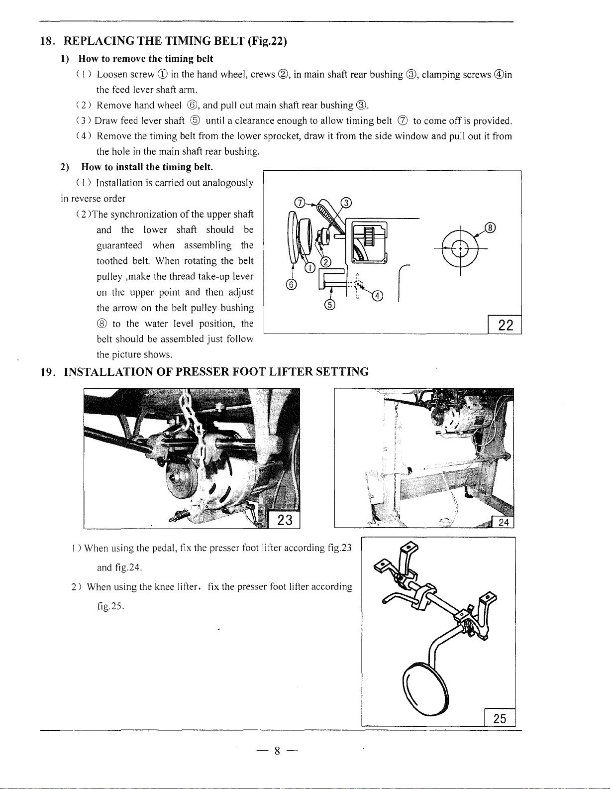
18. REPLACING
1)
How to remove the timing belt
( 1 ) Loosen screw
the feed lever shaft arm.
(
2)
Remove hand wheel ®, and pull
(
3)
Draw feed lever shaft @ until a clearance enough to allow
(
4)
Remove the timing belt from the lower sprocket, draw it from the side
the hole
2)
How to install the timing belt.
(
1)
Installation
in
reverse order
( 2
)The
synchronization
and the lower shaft should be
guaranteed when assembling the
toothed belt.
pulley ,make the thread take-up lever
on the
the
arrow
® to the water level position, the
belt should be assembled
the picture shows.
THE
TIMING BELT (Fig.22)
CD
in the hand wheel, crews ®, in main shaft rear
in
the main shaft rear bushing.
is
carried
When
upper
on
the belt pulley
out
analogously
of
the
upper
rotating the belt
point and then adjust
bushing
just
follow
out
main shaft rear
shaft
bushing®.
timing
bushing
belt
(J)
window
®,
clamping screws
to come
off
and pull out it from
is
provided.
@in
22
19. INSTALLATION
1 ) When using the pedal, fix the presser foot lifter according fig.23
and fig.24.
2)
When using the knee lifter, fix the presser foot lifter according
fig.25.
OF
PRESSER
FOOT
LIFTER
SETTING
-8-
Page 10

A.A
RM
BED
01
AND
ITS
ACCESSORIES__
04------.:..::::~~~
----
-----
05
11
37
Page 11

A.ARM BED
AND
ITS ACCESSORIES
Fig.
No.
AOI
A02
l\03
r\04
A05
A06
,\07
A08
.'\09
AIO
;\I I
A12
t\13
A14
Al5
Al6
A17
Al8
Al9
i\20
i\21
A22
A23
A24
i\25
A26
:\
27
.\
28
1\29
A30
i\31
1132
i\:33
•\:H
t\35
:
\:!6
:\:\7
Part No.
1-1
0209
88001
H3100F2360 Scr
1-1533508001
H
A73
11CH
1-124008206
IIA
307B06 74 Rubber plug
1-14717
88001 Thread take-up lever cover
HA80
0F2020 Screw
H5316B8001 Side plate
HA107Hl013 Screw
1-1
410082060 Hook
H4 100B2090 Washer
H4l00B2080 Wing bolt
H41
00B2070 Hinge screw
1-1
240082070 Frame thread guide upper
1-1472688
1-1240
082080 Screw
1132128
H3200B2l00 Screw
1102 108800 I
1-1533388
1-1
534088001 Throat plate
1-1
5341
B8001
1-15
3378800 I
H5339B8001
1-15334871
11
53388800 I
11
533
18800 I Lo\\er shaft
1-1533288001
1-1200082010
I-IA307B0673
115350B71
114
1 5080 160 Scr
11
2400132100 Thread guide
HA70082060 Screw
1-153
118800 1 Machine bast
1153548800 I
plate
Side
ew
Oil
guard plate
Sere\\
06
0 Spacer
001 Frame thread guide middle
0066 Thread guide
Throat plate base
Screw
001
frame
Screw
Bed
slide side plate left
Sere"
01
Bed slide
Bed slide
side pla
te
right
front metal
ScrC\\
Rubber plug
Rubber plug
0 l Hinge
ew
Fel
t
Description
Pes.
1
9/64
2
(40) X 7
I
9/64
2
(40) X8
I
1
<!>
1
1.8
1
15/64 (28) X
2
I
3 11/64 (40) X
I
1
1/4(2
1/
4(24)X5
4) X20
1
1
1
1
2 3/ 16(28) X
1
I 9/64 (40) X
l
2 11/64(40) X
1
2 11/64(40) X
1
4 9/64(40) X4
1
1
1
11/64
~)
13
<I>
19
(40) X 4
3
1
3
1
8
GB/1'70. 1 M8 X 16
I
2 11/64
I
1
(40) X 8
Remarks
13.
5
6.
5
.7
13
6.
5
18
15
-10-
Page 12

B.
THREAD
TENSION
REGULATOR
08 09
MECHANISM
1 0
11
1 2
13
14
15 16 17
36
35
34
33
32
31
30
29
Jl
__
------------------=18
~------------------19
~
20
25
26
27
28
-11-
Page 13

B.THREAD TENSION REGULATOR MECHANISM
Fig.
No.
801
802
803
804
805
806
H07
808
809
810
811
812
BI:J
814
815
816
817
1318
1319
820
B21
822
1323
824
825
826
H27
B28
1329
830
831
832
B33
H:l4
ll:l5
1336
Part
H2504C6510
H322183142
H322186812
H4705C8001
H4706C8001
HA7311C306
H4707C800 I
H007013050
H322186820
HA300C2030
H322186810
H4708C8001
H4709C8001
H322180683
HA11280693
H330082040
HA71080671
11322180682
HAI0680676
H3306B0661
HA31080702
H4710C8001
HAI1587010
HA31080701
HA31080705
H322180686
H32481 8721
H4713C8001
H324818D21
H4804C8001
H4805C8001
H3230K0751 Screw
H322186817
HG204C8001
H320082100
H322186819
No.
Description
Screw
Tension releasing plate
Tension releasing spring
Screw
Lever
Screw
Mounting plate
E-type ring
Mounting plate
Screw
Nut
Spring
button
Push
Thread tension stud
Thread tension disc
Spring
Thumb nut
Pin
Screw
Thread guide
Tension releasing disc
Spring
Thumb nut revolution stopper
Thumb nut
Thread tension disc
Thread tension stud
Thumb nut
Thread take-up spring
Plate complete
Thread tension stud
Thread tension stud
Pin
Pin
Screw
I
!stopper
I
Pes.
2
9/64(40)
1
1
1
1
1
9/64(40)
1
1
1
1
11/64(40)
2
1
1
1
11/64
2
1
1
2
9/64(40)X6
1
1
1
1
1
1
2
1
1/4(40)
1
1
1
1
9/64(40)
1
1/4(40) X 14.5
1
ll/64
1
1
1
9/64
(40) X
X23
(40) X
(40) X
X3
xs.
X8
X9
6.
Remarks
5
14
10
5
I
-12-
Page 14

C.TAKE-UP THREAD AND
ARM
SHAFT
01
MECHANISM
41
~~
40
14
45
4
51
4~
~
50
54
-
13
--
Page 15

C.
TAKE-UP THREAD AND ARM SHAFT MECHANISM
Fig.
No.
C:OI
COL
C03
C04
CO.'l
C06
C07
C08
(()l)
ClO
Cll
Cl2
C:l3
I
I
(
I
('JH
1'1'1
1~11
I
~'
I
I
~:
I~
I.,'
__
l':'li
('~-~
I
~K
I
~lJ
('',()
I
·:1
I
('.')')
c·;·;
('.j!
(
·:-;:1
l·:Hi
\
t''\N
I
I
(II
I
Part No.
H3100C2060
113 I OOC2050
H3100C2040 Thread take-up link
H0209F8001 Pin
H5305C8001
HAIOOC2020 Set screw
H5306C8001 Holder
HAI05D0662 Screw
IIA307C0662 Screw
H5310C8001
H53JIC8001 Pin
f-1240500663 Oil
HAIOOC2060 Screw
IIA I
II
I)
:r,J
II
OOC2070
115315CSOOI
11531
6CSOO
1153
17C800 I
I-IAIOOC2020
J!Ci204DSOOI
li;\307C0662
11Ci205D8001
I
,.,
11201410068 Oil
.~
112000C2030 Felt retainer
l
1153140\011 I
I
c
.)
115J26C800 I Arm sha!i bushing (middle)
115327C800 I
115332C8001 Feed cam (right)
Jl;\307C0662
115329C8001
115330U\OO
1120JIICJ06
110070
I 0260 Stop ring
113205C0661 Spring stop ring
. '
I Ll205C0661 Stop ring
!!A! !3!068·1
115337C800 I
I
L>\
I 00121.10
I
)/-
ll53J(J(
113208110661
IJ;\JI3F0684
\'J
1141
10
I~
OOC2040
Jl;\
II
OD06
11533RCSOOI
Needle bar connecting link
Oil wick
Thread take-up lever
Needle bar crank
wick
Scre11
Arm shaft bushing
I
!'cit
Felt
Screw
Feed cam
Scre1v
Upper feed driving rod
kit
Arm
shaft
Felt
Screw
Connecting
I Felt
lloldcr
SCt'C\\
l'ulky
(upper)
I
~crew,
·~oo
i
/\rill
..
snail ousnmg (nglltl
Needle bearing
Scrc11
72
Balance
Screw
11
Cog belt
(left)
(kli)
rod for upper
, , . . . .
heel
Description
ked
Pes.
1
1
1
1
1
15/64
1
1
1/4(40)
1
1/4(40)
1
1
1
1
9/32
1
9/32
1
1
1
1
15/64
1
1
1/4(40)X6
2
I
I
1
1
1
I
1
1/4(40)X6
2
I
1
1
I
2
1
l.l
bH;!KJ X k.
I
I
I
I
I
115/64
6004ZZNR/5K
2 15/64 (28) X
2 l.'i/61 (28) X
(28) X
X4
X6
(28) X
(28) X
(28) X
(21-l)
Remarks
10
13
10
10
X 8
8.
12
:]
I
5
Page 16

C.TAKE-UP THREAD AND ARM SHAFT MECHANISM
Fig.
No.
C43
C44
C45
C46
C47 H4714D800l Pin
C48
C49
C50 H007013025 E-type stop ring
C51
C52
C53
C54 H471708001 Lever for pulley
C55
Part
No.
H5334D800l
H5333D800l
HAI04F0654
H4721D8001 Screw
H471808001 Pin
H47160800l
H4719D8001 Short lever for pulley
H471308001 Long lever for pulley
H471508001 Pin
H472308001 Screw
Pulley
Shaft for pulley
Screw
Spring for pulley
Description
Pes.
l
I
I 15/64(28)x I
l5/64(28)x8.5
I
I
I
I
I GB/T896 2.5
I
I
I
1
15/64(28)x4 5
2
Remarks
0
-15-
Page 17

D.NEEDLE BAR AND
04
ROTATING
05 06
HOOK
SHAFT
MECHANISM
~
22
24---l
50
51
56
57
47
-
16-
Page 18

D.NEEDLE BAR AND ROTATING HOOK SHAFT MECHANISM
Fig.
No.
DOl
002
003
004
005
006
007
008
009
010
011 H5319H8001
012
013
014
015
016
017
018
019
020
021 HA7311C006
022
023
024
025
026
.
027
028
029
030
031 H410268016
032
033
034
035
036
037
038
039
040
041
042
043
Part
No.
H5325F8001
H5324F8001
H602040260
H5316F8001
H5319F8001
H5320F8001 Felt clip
H5328F8001
H5327F8001 Needle bar rock shaft bushing (left)
H5326F8001 Washer
H5320H8001
H5316H8001
H5317H8001
H2010J0066
H5314H8001
HA700F2100 Screw
HA800F2020
H3129F0692
H4722F8001
H320406513 Felt
H5322F8001 Thread guide for needle bar
H3129F0691 Screw
H4740F8001
HAIOOC2170 Screw
H532007101 Rotating hook
HIIOOE2010
H533708001 Screw
H532308001
H416220216 Guide plate slide block
H532908001
H532608001 Felt
H532708001 Oil wick
H2204C0651
H425050120 Screw
H005004050 Washer
H532508001
HG208E8001 Bushing
HG209E8001 Bushing
HG210E8001
HG211E8001
H530408001
Description
Needle bar rock shaft
Slide block
Pin
Needle bar rock frame
Felt
Needle bar rock shaft bushing (right)
Screw
Link
Link
Screw
Nut
Crank
Screw
Needle bar
Needle bar connecting stud
Screw
Needle
Bobbin
Rotating position guide
Guide plate pin
Guide plate
Screw
Rotating hook bracket
Washer
Bevel gear for hook shaft
Rotating hook shaft
Pes.
I
I
I A4x26
I
I
I
I
I
I
I J5/64(28)x23.5
I
I
9/32(28)x 13.3
2
9/32(28)x3.6
2
I
IJ/64(40))x
I
I J5/64(28)xJ3.5
I
I
I
I 9/64(40)x8.5
I
I 3/32(56)x2.5
I
OPxl7
I l/8(44)x4.5
I
KRT341NR
I
BO-PF541
9/64(40)x!O
I
I
I
I
I
I
I
I 9/64(40)x5
!V!5x!2
2
2
I
I
I
I
I
#23
I
Remarks
10
-17-
Page 19

D.NEEDLE
BAR
AND
ROTATING
HOOK
SHAFT
MECHANISM
Fig.
No.
044
045
[)46
047
048
[)49
050
051
052
053
D54
[)55
D56
[)57
D58
[)59
D60
D(J
D62
Part
No.
H5306E8001 Feed eccentric
HA305E0662
HG212E8001
HAI08C0663
1-!531508001
1-!531608001
1-!530808001
HA3411D308
H4107D0671
1-!41
0700672
H530908001
H609020120
HG206E8001
HE051C8001
HG205E8001
11531908001
l!A34ll
I
HA
0308
1!5314f800
700F2l
I
00
Set screw
Bevel
gear
for hook shaft
Set
screw
Rotating
Oil
Recessed
Set
Safe clutch
Safe
Safe
Safe clutch shaft pin
Rotating
Screw
Rotating
Oil wick
Screw
Guide
Screw
hook
wick
wheel
screw
bushing
clutch
spring
clutch
shaft
hook shaft
hook
for slide block
shaft
shaft
Description
bushing
collar
bushing
(left)
(right)
Pes.
I
2
I
3
I
I
2
I
I
I
I
I
2
I
I
I
2
15/64(28)x4.5
I/4(40)x7
15/64(28
A2xl2
SM
15/64(28)x7
ll/64(40)x7
)x 7
l/4"(40)x5.5
Remarks
I
I
I
I
I
I
-18-
I
Page 20

E.PRESSER
FOOT
FEEDING MECHANISM
16 15 14
~
32
33
re----50
~51
40
39
30
48
-19-
Page 21

E.PRESSER FOOT FEEDING MECHANISM
Fig.
No.
EO!
E02
E03
E04
E05
E06
E07 HG211F8001
E08
E09
EIO
Ell
El2
El3
E14
LIS
Ll6
17
I
I I X
El9
I
20
I
21
I
22
123
1:24
I
25
126
127
12X
I
29
uo
I
31 I 15331
U2
1-.33
I ).J
L35
IJ6
137
J]X
UlJ
40
I
141
142
143
Part No.
H4754E8001 Presser bar
HG204F8001
HAIOOC2020
H3200E2020 Screw
H5331G8001
1-!200012030
HG205F8001
H2400G2140
HAII7H0692
HG206F8001
H3100G2070
HG207F8001
1-!31
OOG221
HE04008001 Screw
I 1609025 I 80 Pin
f-13
107G066 I
HG208F8001
f-1200410655
I
13 I OOG2050
I
13 I 09CI0651
I
IG209FXOO
113IOOG2130
II!\
I
OOC2190
1Ki2 I OF800
I 15318G800 I
115314G800 I
1!4727E8001
11Ci212F800
113 I OOF2070
FXOO
I
131
OOF2
I 00 Bushing
113112F0663
I
1.:\
IOOB2110
113112F0661
113100F2010
1131
001"2020
113100F2030
115332F7101
11200012120
113115F0672
113100F2150
H3100F2130
Presser bar lower bushing
Screw
Presser foot aeey
Connecting pim roller
Presser bar bracket guide
Guide plate base
Presser spring regulator
Nut
Presser spring
Hand lifter
Hand lifter pin
0
Lifting bracket guide block
Screw
Presser
lifting lever base
Guide shaft hinge screw
Thread release spring
Thn:ad release guide assy
I
Presser bar
Hinge screw
Screw
I Screw
Hanging rod
Screw
Twist spring
I
Screw
Walking bar
I
Walking foot
Upper
Sere\\
Screw
Upper feed
L shaped link
Walking bar driving link
Walking bar spring
Walking bar spring
Upper feed
Connecting stud
Hinge screw
litting lever
feed
driving shati
'tud
dconnecting link
spring rod
Description
Pes.
I
I
I
I
I
I
I
I
I
I
I
I
I
I
I
I
I
I
I 3116(28)
I
I
I
I
2
2
I
I
I
I
I
I
2
I
2
I
I
I
I
I
I
I
I
I
I
Remarks
15/64(28)x I 0
1/8( 44 )x4
112(28)
17/64(24)xJ7.5
ll/64(40)x
t/i'ili'!31H6-00483
l/4(24)x7
11/64(40)x8
15/64(28)x I
3/16(28)x4.5
ll/64(40)x5
1/4(28)
7/32(32)
14
0
5
-20-
Page 22

E.PRESSER
FOOT
FEEDING MECHANISM
Fig.
No.
E44 HE045D8001
E45
E46
E47
E48
E49
E50 H5334F8001
ESI H2004J0067
E52 H5315F8001
E53 HG213F8001 Felt
Part
No.
Washer
H4728H8001 Washer
H3100F2160
H3112F0662
HAIOOC2040
H3115F0671 Screw
Nut
Nut
Screw
Walking bar retaining plate
Screw
Walking bar guide roller
Description
Pes.
I
I
I 7/32(32)
I 1/4(28)
ll/64(40)x5
I
J/4(28)xJ6
I
I
9/64(
2
I
I
Remarks
5
40)x7
0
I
-21-
Page 23

F.STITCH
---
REG
ULATOR
MECHANISM
-22-
Page 24

F.STITCH
REGULATOR
MECHANISM
Fig.
No.
FOI
F02
F03 H5305H8001
F04
F05 H5306H8001 Feed driving rocker shaft
F06 H5307H8001 Bushing
F07 HA3411D308 Screw
F08
F09 HA711B0681 Screw
FlO H5309H8001
Fll
F12 H5311H8001
F13
F14 HA720F0681
F15 HA7421F120 Stitch dial assy
F16 HA720F0686 Screw
F17 HA700F2030 Pin
F18
F19 H5339H8001 Reverse feed lever shaft
F20
F21
F22
F23 H5323H8001 Control lever crank link A
F24
F25
F26 H5322H8001 Feed driving rocker shaft arm
F27
F28 H5325H8001
F29
F30 H5329H8001 Hinge screw
F31
F32
F33
F34 H41111E204 Oil felt
F35 H5304E8001 Feed dog
F3n
F37
F38 H5315E8001 Hinge screw
F39
F40 H5309E8001
F41
F42
F43
Part
No.
H5308H8001
HAIOOC2020
HAIOOF2130
H5315H8001 Feed rocker shaft crank pin
H5313H8001
H5334H8001
HAIOOF2090 Spring
H5327H8001 Control lever crank
H5343H8001
HA34110308
H5333H8001
H5324H8001 Hinge screw
HA104G0012
HG207G8001 Tension spring
H5330H8001 Suspension hook
H200012050
HG205G8001 Feed bar crank
HA700F2100
H5307E8001 Feed bar support
H5308E8001 Feed bar support plate
H5314E8001 Screw
H5312E8001
HAIOOC2020
Feed driving rocker hinge pin
Screw
Feed driving rocker
Screw
Slide block
Feed driving rocker arm
Slide block shaft
Feed regulator
Needle feed regulating spring.
Screw
Screw
Hinge screw
Screw
Nut
Screw
Screw
Screw
Feed bar link
Screw
Description
Pes.
I
1 15/64(28)x
1
15/64(28)
1
I
I
)5/64(28)
1
I
9/64( 40)x4.5
2
2
1
I
I
I
I
3/16(28)x
I
1
I
I
I
3/64(32)x
I
15/64(28)x7
I
I
3/16(32)x8 5
3
3/16(32)x
I
I
3/16(28)x
I
3/16(32)
I
I
9/64( 40)x4
I
I
9/64( 40)x8
I
I
I
I
ll/64(40)x7
I
I
I
I
1/4( 4Q)x9
2
I
l/8(44)x6.3
4
IJ/64(40)x7.5
I
I
15/64(28)x I 0
I
10
X 7
12
16
13
12
Remarks
5
-23-
Page 25

F.STITCH REGULATOR MECHANISM
Fig.
No.
F44
F45
F46
F47
F48
F49
I
50
F51
F52
F53
F54
F55
t·sc,
I
57
F58
F59
F60
F6l H5312H8001
162
F63
F64
Part No.
H5313E8001
H5320E8001
H5316E8001 Nut
H5317E8001
H5319E8001 Thrust coolar
H6039G8001
H5321E8001 Bushing rear
HAIOOC2020 Screw
HAIOOF2130 Screw
H5332H8001
H5338H8001
H5335H8001 Hinge pin
ll5342H800 I Feed lever
llA34ll
HAII3F0683 Screw
D308
H5336H8001 Screw
Hi\
113
F0684 Screw
H53IOE800l Feed bar support
HI::ll4E8001 Screw
llEll5E800l
Description
Feed rocker link shaft
Bushing front
Feed rocker shaft
Screw
Feed lever connecting link B
Feed regulator bushing
Screw
Oil
wick
Stop ring
Pes.
I
I
2
I
I
2
I
I
I
I
I
I
I
I
I
I
2
I
I
I
I
1/4
(40)
II/64(4Q)x3.8
15/64(28)x I 0
15/64(28)
15/64(28)x 7
15/64(28)x
3/16(28)x6.5
15/64(28)x8.5
ll/64(40)x4
14.3
Remarks
I
I
-24-
I
Page 26

G.ACCESSORIES
~19
20
21
~22
~-ri
09
10
26--®
27-@
® @ ®
® ® ®
24
?
37
17
18
(
~
12
02
04
13
-25-
Page 27

G.ACCESSORIES
I
Fig.
No.
GO!
G02
G03
G04
G05
G06
C:i07
CJ08
G09
GIO
Gil
Gl2
Cil3
(i
(i
Ci
Cil7
Ci
(Jil)
Ci20
(i21
Ci22
(i2J
Ci24
(i25
(i2!J
Ci27
Ci28
Ci2l!
( ,.)()
(
i31
i32
(
(i33
i34
(
(
i35
(i36
(
i3
CJ3X
(i39
(i40
Part No.
H6307L8001 Belt cover (upper)
1-15311
I800I
1-1200000360 Screw
1-153
I21800I Belt cover (left)
H6722N8001
H0207L8001
H0206L8001
HA
706S0067 Bobbin winder assy
1-1801045200
HA30012230 Washer
HA20012030 Thread stand assy
HA
I
0610668
HAI0610665 Knee lifter plate
14
I-IAI06J0666 Knee I ifter bracket
15
HAI0610667 Screw
HA
I
I('
I X
7
0610662
HPGIOOE203
I lPG I
OOE202
114740f800I Needle
lli\30012070
fli\300.12200
lli\300J221 0 Screw driver (small)
IIIIOOE2010
11200400069 Oil assy
11403080750 Screw
1100500 I 080 Washer
11003002080 Nut
11201500065 Knee lilier
11802045250 Wood screw
1120 I 50006 7 Sl:t
lli\300J2180
11201500069
11201500066 Knee lilicr shali
1120
1600070 Coil spring
11531318001
II
130000
11120418001
lli\10012180 Vinyl covcr I
11G2081-1800
1131041-10651
Belt cover (right)
Washer
Screw
Washer
Wood screw
Knee lifter cover
Knee lifter shaft
Chain
S shaped hook
driver (large)
Screw
driver (middle)
Screw
Bobbin
blore
Scre1~
Knee lilier shalt
!Connector
I 060 Socket wrench
I Finger gusrd
I Lever I
Knee lifter shaft
Description
Pes.
I
I
I
I
2
I
I
I 5/64(28)x8
4
2
I
4.5x20
2
2
5
I
I
I
I
I
I
I
2
DPxi7
2
I
I
I
2
I
M8x75
4
4
4 M8
2
4.5x25
4
I
5
I
I
I
I
1
6mm
I
I
1
l
1164(
Remarks
40) X 6
23#
I
I
-26-
Page 28

SHANGHAI HUIGONG
N0.3
SEWING
MACHINE
FACTORY
ADD: 1418, Yishan
Zip
Code: 201103
Overseas
I
Business:
Road,
TEL:
Shanghai,
China
86-21-64853303 FAX: 86-21-64854304
E-mail: highlead@online.sh.cn http://www .highlead.com.cn
The
description covered
in
this
manual
is subject
to
change
for
improvement
of
the conunodity without notice
2008.2. Printed
 Loading...