

Page 1
iii.
® HIGHLEAD
GC22618-1B
Cylinder-Bed Unison Feed
Sewing Machine
INSTRUCTION MANUAL
CATALOG
Page 2
1.
Safety precautions:
1)
When turning the power on, keep your hands and fingers away from the
area around/under the needle and the area around the pulley.
off
2) Power must be turned
operator leaves the seat.
3) Power must be turned
removing the
4) Avoid placing fingers, hairs, bars etc., near the pulley,
winder pulley, or motor when the machine is in operation.
5) Do not insert fingers into the thread take-up cover, under/around the
needle,
"V"
belt, adjusting the machine, or when replacing.
or
pulley when the machine is
when the machine is not in use, or when the
off
when tilting the machine head, installing
"V"
belt, bobbin
in
operation.
2. Precautions before starting operation:
1)
When a new sewing machine
of
direction
machine nameplate.
the pulley with the power on.
2) Verify the voltage and phase (single or three) with those given on the
is
first turned on, verify the rotational
3. Precautions for operating conditions:
1)
Avoid using the machine at abnormally high temperatures (35°C or
or
higher)
low temperatures ( 5
2) Avoid using the machine in dusty conditions.
OC
or
lower) .
or
4. Specifications:
Max. Sewing Speed
Needle
Needle Bar Stroke (mm)
Thread Take-up Lever
Max.Stitch Length (mm)
Presser Foot Stroke
Alternating Movement (mm) 2.0-6.0
(rpm)
~troke
(mm) 72.1
Byhand(mm)
By knee (mm)
1
2,200
DPX17
34.2
6
8
14
22#
Page 3
5.
Preparation
1)
CleaniDg 1he
Before leaving
rust-preventive
during stoJage
1)
Examination
Though
factory, the machine parts
banspotlalion.
cleaning
evay
the
before
machine
the
grease,
and
shipment. This grease must
machine is
~
joiL A thorough examination must
machine..
starting
factory,
which
Tmn
may
inspeded
may
the balance wheel
obsbuclion, parts collision, uneven
adjuslmcot
use
for
wbich
material.
must
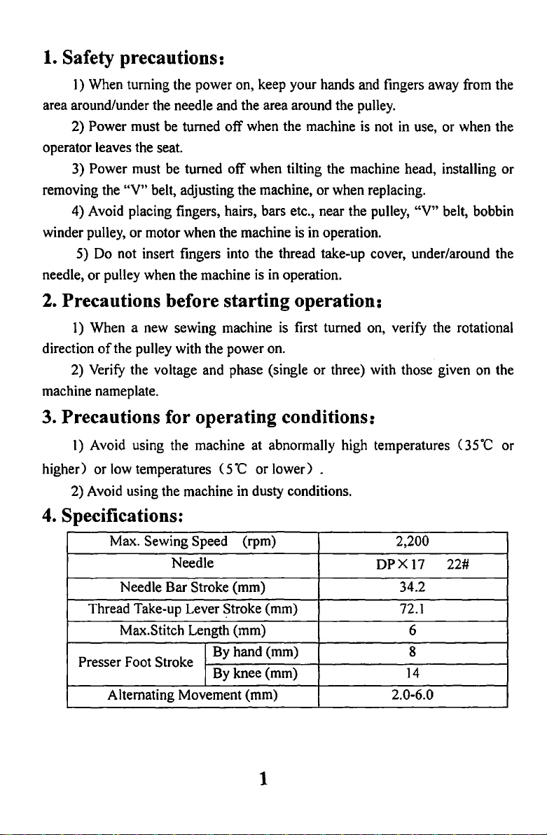
3)
Lubrication
When
a
new
a long time is
anowheads
Please
Please
use~
ap6ft
be
made
machine
to
~need
spindle
pnsser
accordingly before run-in operation.
begins
to
be
used
to
be
oil
foot
operation:
the
machine
be
hardened
be
and tested slricdy before leaving the
be
loose
or
resislance
be
again,
lubricated.Fig.l)
wheo
used
it
the
or
or
an
must
machine
parts
are
coated with
and
c:ontamioated
removed with gasoline.
deformed
to
abnormal noise.
old
be
lubricated fully.
after long distance
be
performed after
see
if
there is running
If
these
machine which left
(fhe
is
operated without
by
dust
exist,
out
spots
of
Fig.
I
2
Page 4
4)
Run-in
A
new
being lubricated sufficiently, each
increasing speed
done.
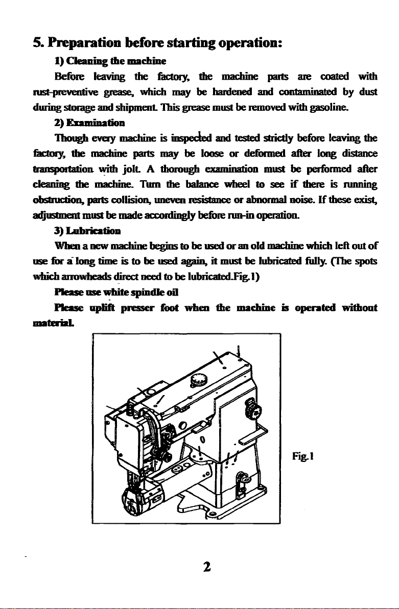
6.
How
Note:
This machine
according to the thread rightly. (Thread
freely.)
Insert
tighten
groove
operation
machine runs
to
the maximmn according
to
attach
Before attach the needle, be
's
the
needle
the
screw keeping
in
the
needle
Long groove
facing
to
the
left
.
at
a low speed ( 1600rpm)
a needle (Fig.2):
needle size is DPX17
until
it
boaoms.
facing
to
the
1he
and
lang
left:.
of
for
about a month after
parts will achieve its best state. Then
to
sure
need
the natme
to
tmn the
#122.
Needle
to
pass
X
power
size
the
pinhole
of
the work
switch
must
musl
ofi.
be selected
of
the needle
X
he
Fig..2
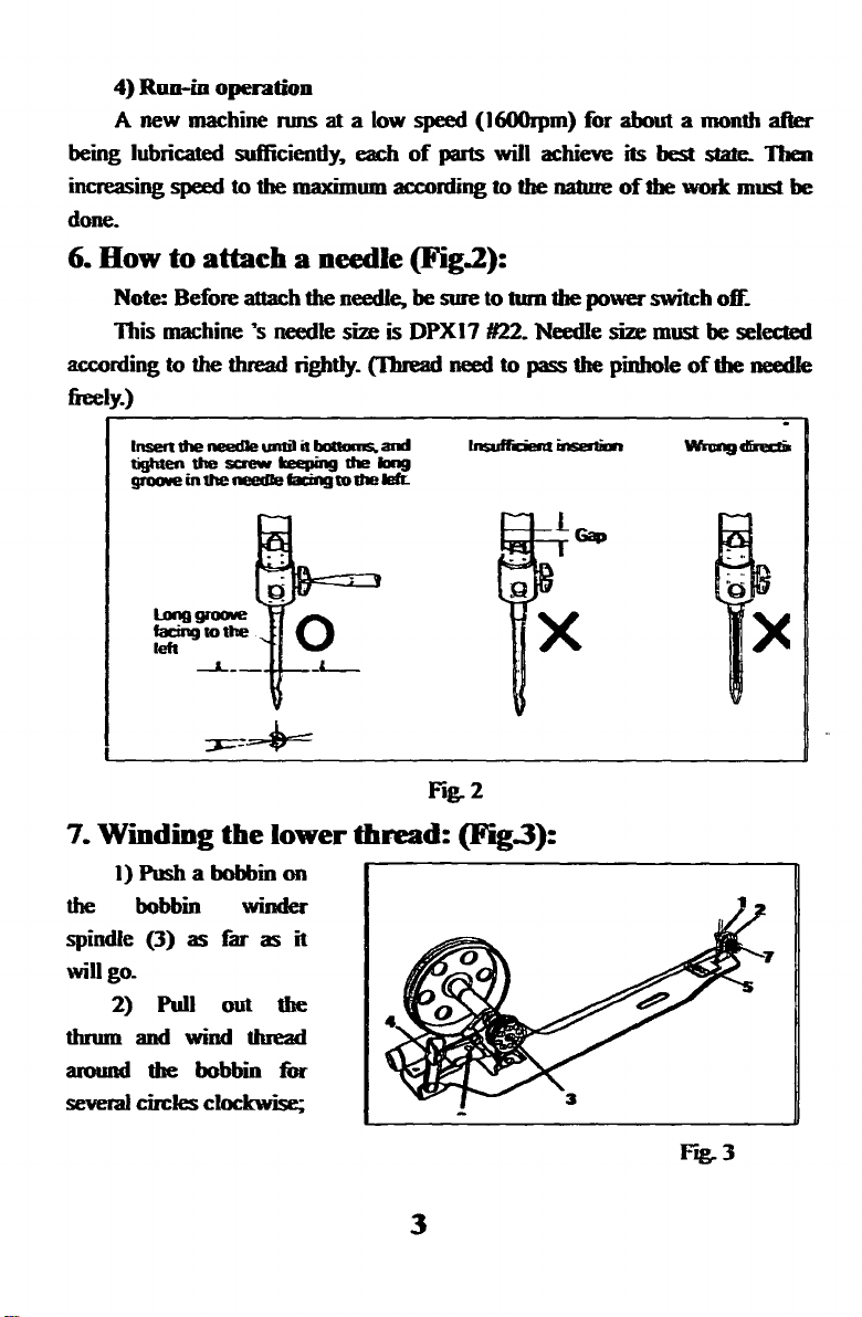
7.
Winding
1) Push a bobbin on
the
spindle
will go.
bobbin
(3)
2)
Pull
as
the
winder
far
out
lower
as
it
the
thn2d:
(Fig.3):
r--------------.,.
thnnn and wind thread
around the bobbin
several
circles clockwise;
for
F"rg..
3
3
Page 5
-----
3) Push the lever 4 backward so that the wheel
"V" belt, then start the machine.
4) The pulley will separate from the "V" belt automatically after the
bobbin is filled with thread.
8. Adjustment
I)
In case
Loosen the screw
right or to the left as may
2) Adjustment
Adjusting screw
screw will increase the amount, otherwise the amount
decrease.
3) Winding strength
Adjusting the nut
Adjusting screw 6 can adjust the amount
screw will increase the amount, otherwise the amount
decrease.
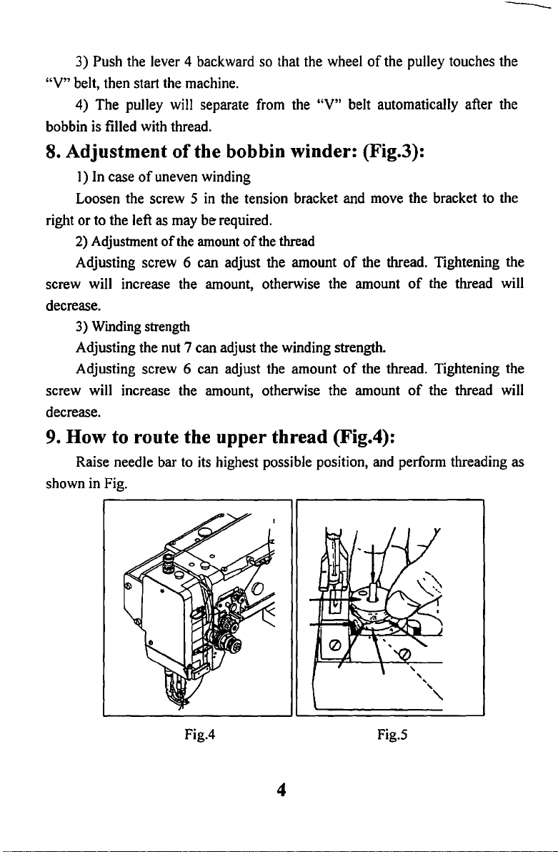
9.
How
shown in Fig.
to route the upper thread (Fig.4):
Raise needle bar to its highest possible position, and perform threading as
of
the bobbin winder: (Fig.3):
of
uneven winding
5
in
be
of
the
amount ofthe thread
6 can adjust the amount
7 can adjust the winding strength.
the tension bracket and move the bracket to the
required.
of
the pulley touches the
of
the thread. Tightening the
of
the thread will
of
the thread. Tightening the
of
the thread will
Fig.4 Fig.S
4
Page 6
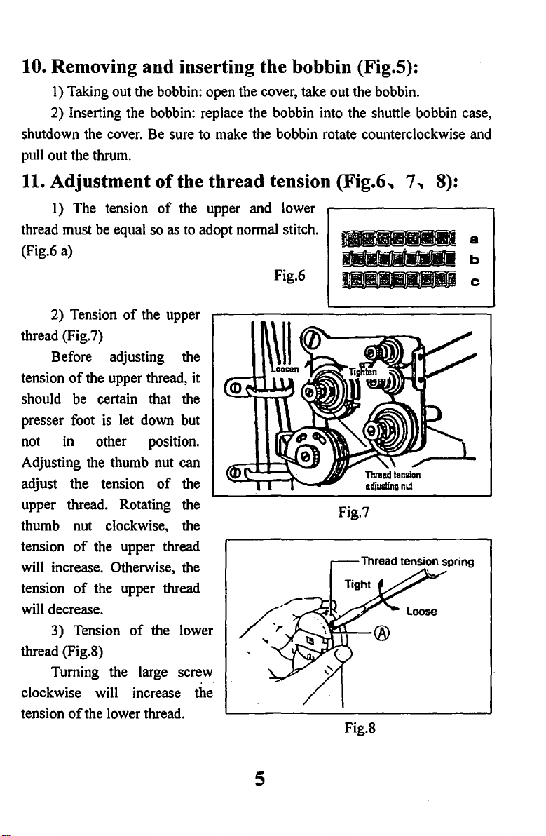
10. Removing and inserting the bobbin (Fig.5):
1)
Taking out the bobbin: open the cover, take out the bobbin.
2) Inserting the bobbin: replace the bobbin into the shuttle bobbin case,
shutdown the cover. Be sure to make the bobbin rotate counterclockwise and
pull out the thrum.
11.
Adjustment
1)
The tension
thread must be equal so as to adopt normal stitch.
(Fig.6 a)
of
the thread tension (Fig.6,
of
the upper and lower
:.
Fig.6
7,
8):
T]cJCJif:fOC!CJ-
a
b
c
2) Tension
thread (Fig.7)
Before adjusting the
tension
should be certain that the
presser foot
not in other position.
Adjusting the thumb nut can
adjust the tension
upper thread. Rotating the
thumb nut clockwise, the
tension
will increase. Otherwise, the
tension
will decrease.
thread (Fig.S)
clockwise will increase the
tension
of
of
of
3) Tension
Turning the large screw
of
of
the upper
the upper thread, it
is
let down but
of
the
the upper thread
the upper thread
of
the lower
the lower thread.
Fig.7
Fig.S
5
Page 7
Otherwise, the tension
of
the lower thread will decrease.
12. Adjustment
I)
Pressure should be adjusted according to the
material to be sewn.
2) Pressure on both the walking foot and the
presser foot can be adjusted.
3)
Sewing pressure should be adjusted to the
minimum required strength.
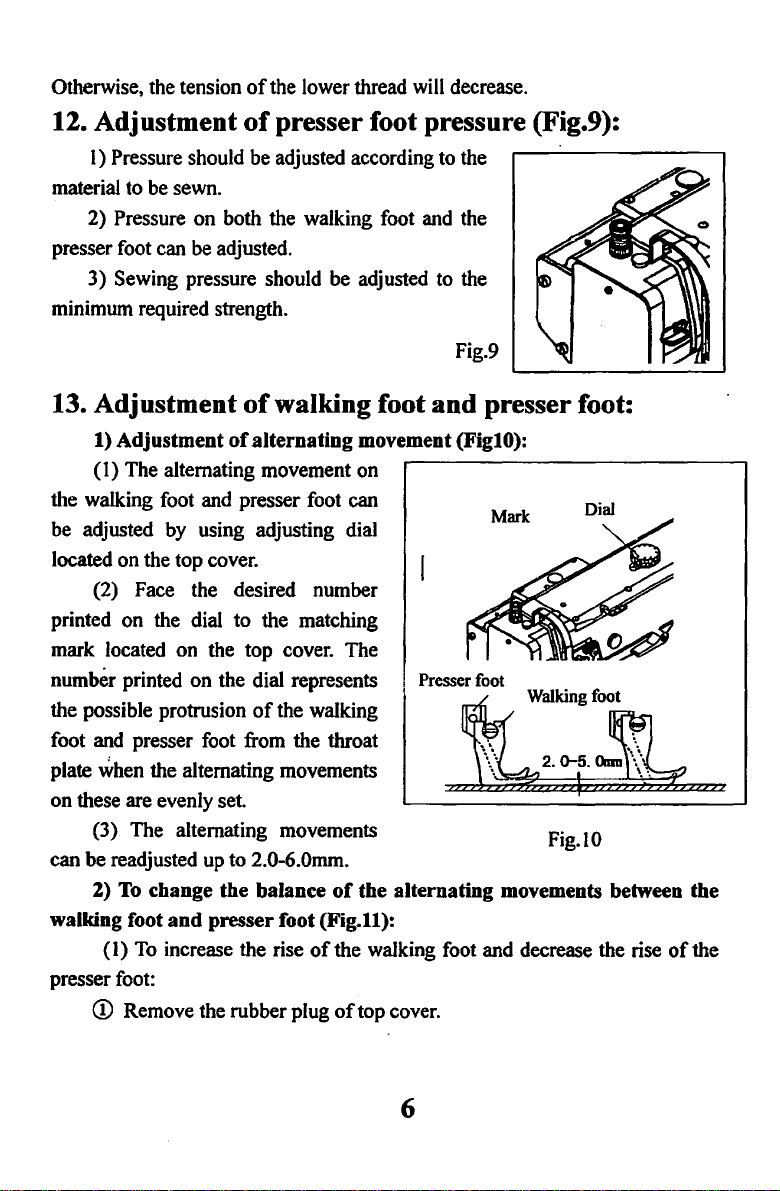
13. Adjustment
1) Adjustment
(I)
The alternating movement on
the walking foot and presser foot can
be adjusted by using adjusting dial
located on the top cover.
(2) Face the desired number
printed on the dial to the matching
mark located on the top cover. The
number printed on the dial represents
the possible protrusion
foot and presser foot from the throat
when the alternating movements
plate
on these are evenly set.
(3) The alternating movements
can be readjusted
2)
To
change the balance
walking foot and presser foot (Fig.ll ):
(I)
To
increase the rise
presser foot:
CD
Remove the rubber plug
of
presser foot pressure (Fig.9):
of
walking foot
of
alternating movement (FiglO):
of
the walking
up
to 2.0-6.0mm.
of
the alternating movements between the
of
the walking foot and decrease the rise
of
top cover.
Fig.9
and
presser foot:
...---------------.....,
Presser foot
~Walking
kto-5.~
Fig.IO
Dial
h
foot
of
?????
the
6
Page 8
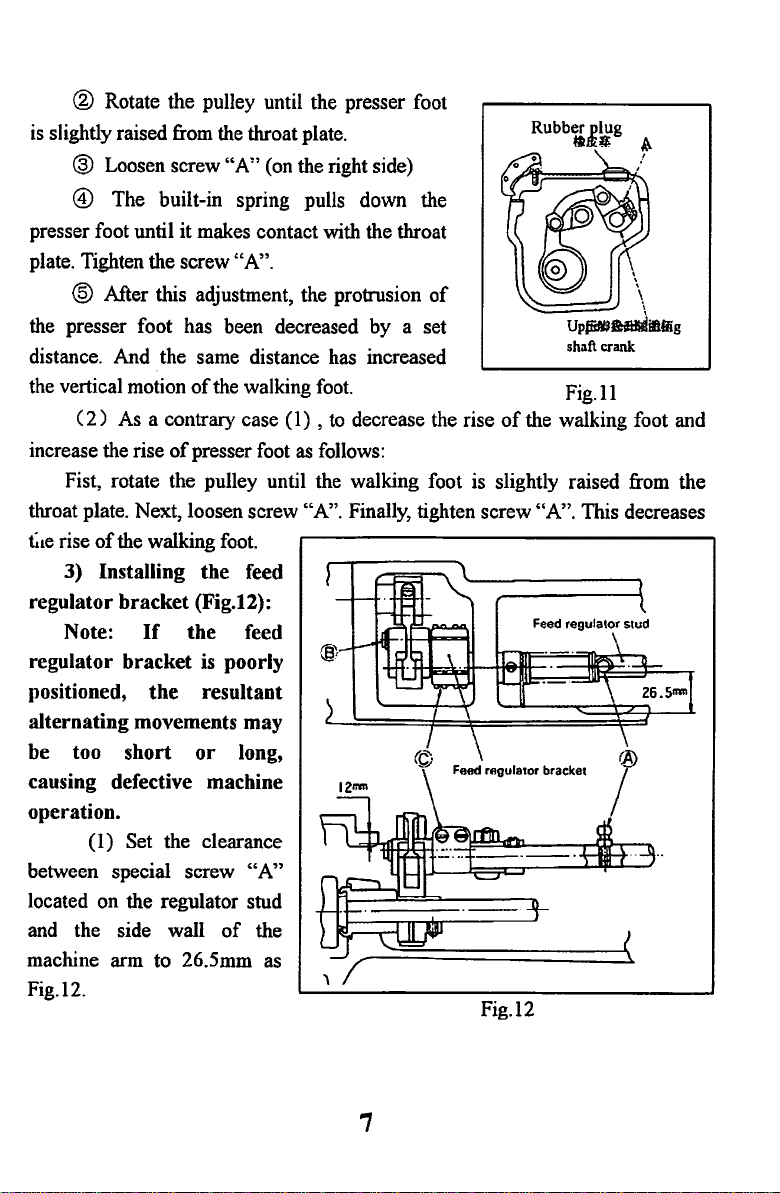
® Rotate the pulley until the presser foot
is
slightly raised from the throat plate.
@ Loosen screw
"A"
(on the right side)
@ The built-in spring pulls down the
presser foot until it makes contact with the throat
plate. Tighten the screw
@ After this adjustment, the protrusion
the presser foot has been decreased by a set
distance. And the same distance has increased
the vertical motion
( 2 ) As a contrary case (1) ,
increase the rise
Fist, rotate the pulley until the walking foot is slightly raised from the
throat plate. Next, loosen screw "A". Finally, tighten screw "A". This decreases
Lte
rise
of
of
the walking
"A".
of
the walking
presser foot as follows:
foot.
foot.
to
decrease the rise
of
3) Installing the feed
regulator
regulator bracket
positioned,
Note:
bracket
If
the
(Fig.12):
the feed
is
poorly
resultant
alternating movements may
be too short
or
long,
causing defective machine
operation.
(1) Set the clearance
of
"A"
the
between special screw
located on the regulator stud
and the side wall
arm
machine
Fig.12.
to 26.5mm as
Rubber plug
•&I;
shaft crank
Fig.
II
of
the walking foot and
Fig.l2
t
7
Page 9
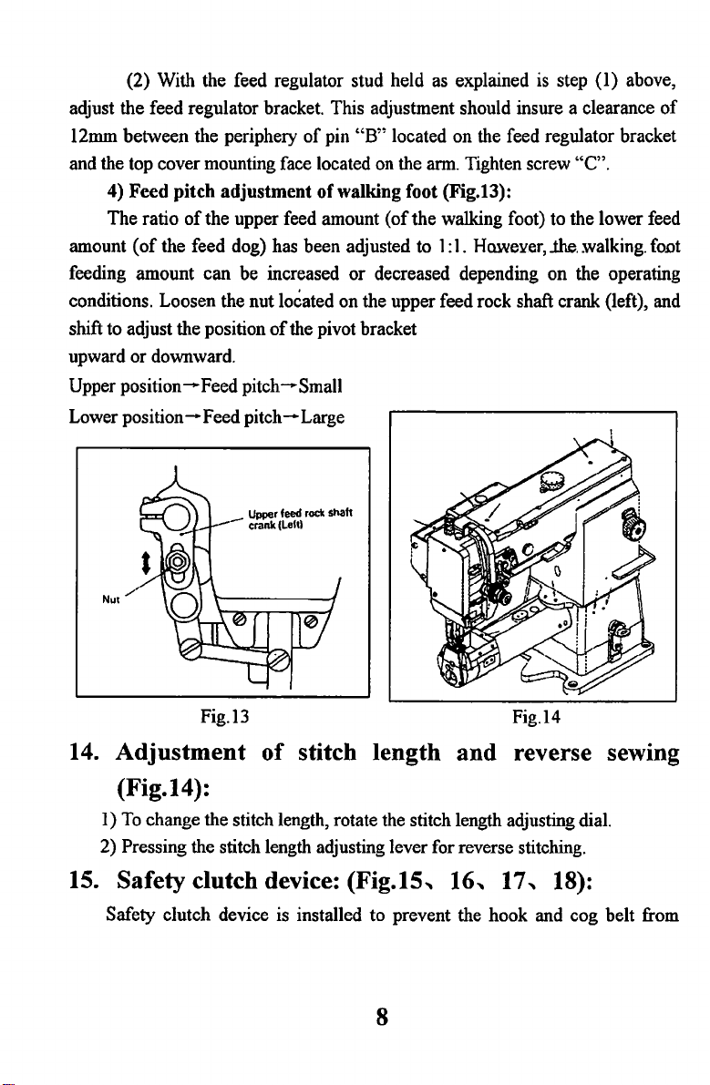
(2) With the feed regulator stud held as explained is step (1) above,
adjust the feed regulator bracket. This adjustment should insure a clearance
12mm between the periphery
and the top cover mounting face located on the arm. Tighten screw
4)
Feed
pitch
adjustment
The ratio
amount
feeding amount can be increased
conditions. Loosen the nut located on the upper feed rock shaft crank (left), and
shift to adjust the position
upward
Upper
position-Feed
Lower
position-
of
the upper feed amount
(of
the feed dog) has been adjusted to 1 :1. Hawe¥er, lhe . .walking.
or
downward.
pitch-Small
Feed
pitch-
of
pin
"B"
of
walking foot (Fig.13):
or
of
the pivot bracket
Large
located on the feed regulator bracket
"C".
(of
the
walking foot) to the lower feed
decreased depending
on
the operating
of
fo.ot
14.
Adjustment
Fig.l3
of
stitch length
and
Fig.l4
reverse sewing
(Fig.14):
I)
To
change the stitch length, rotate the stitch length adjusting dial.
2) Pressing the stitch length adjusting lever for reverse stitching.
15. Safety clutch device: (Fig.15,
Safety clutch device is installed to prevent the hook and cog belt from
16, 17,
18):
8
Page 10
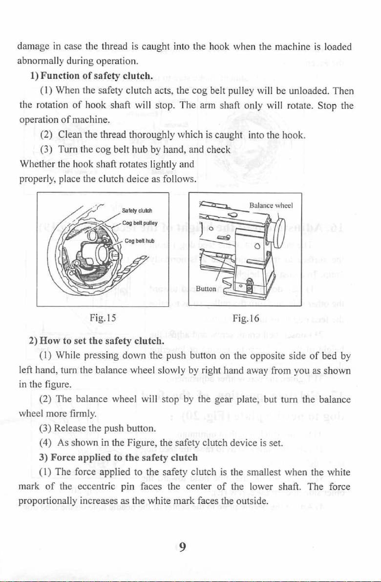
damage in case the thread is caught into the hook when the ma chine is loaded
abn
ormally durin g operation.
1) Function
(I)
the rotation
ope
ration
(2) Clean the thread thoroughly
(3) Turn the
Whether the hook shaft r
properly, place the clutch dei
of
safety clutch.
When the safety clutch acts, the
of hook
of
machine.
shaft wi
cog
belt hub by hand, and check
Fig.
IS
ll
stop.
which
otates lightly and
ce
as follows.
The arm
cog
belt pull
is
ey
will
shaft only wi
caug
ht into the hook.
Fig. l6
be
unloaded.
ll
rotate. Stop the
Then
2) How to
( I) While pressing down
left hand, turn the balance wh
fi
in the
(2)
wheel more firml
(3)
(4) As shown in the Figu re, the safety clutch device is set.
3) Force applied to
(I)
mark
proportiona
set
the
safety clutch.
the
push button on the opposite side
ee
l slowly by right hand away from you as shown
gure.
The balance wheel will stop by
y.
Relea
se
the push button.
the
safety clutch
The
force
applied
of
the eccentric pin faces th e center
ll
y increases
to the safety clutch is the smallest
as
the white mark faces the outsid
the
gear plate, but
of
the
tum
when
lower shaft.
e.
of
bed by
the
balance
the white
The
force
9
Page 11
(2) To adjust
the eccentric pin.
(3) After the adjustment, make sure to fasten the set screw.
the
force slide the timing belt, loosen the set screw, and turn
Low
Shaft
Eccentric
Pin
Fig.17 Fig.
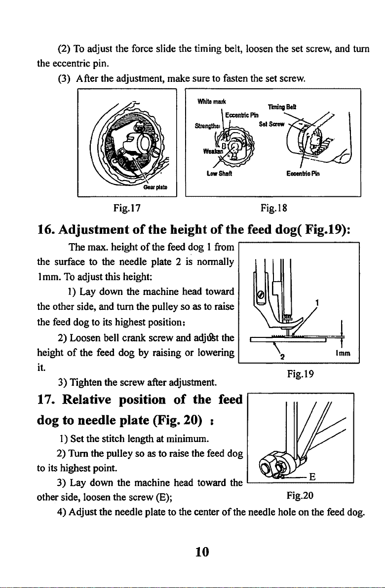
16. Adjustment
The
max. height
the surface
to
the needle plate 2 is normally
of
the height
of
the feed
I mm. To adjust this height:
I)
Lay
down
the machine head toward
tum
the
the other side, and
the feed
height
it.
dog
to
its highest position;
2)
Loosen bell
of
the
feed
3)
Tighten the screw after adjustment.
crank
dog
pulley
screw and
by
raising
17. Relative position
dog to needle plate (Fig.
I)
Set the stitch length at minimum.
2)
Tum
the
pulley
so
as
to
raise the feed
to
its highest point.
3)
Lay
down
the machine head toward the
other side, loosen
4)
Adjust the needle plate
the
screw (E); Fig.20
to
dog
so
as to raise
adj&t
or
lowering
of
the feed
20) :
the center
IS
of
the feed dog( Fig.19):
1 from
the
2
Fig.I9
dog
L-----------'
of
the needle hole
on
the feed dog.
10
Page 12

5) Tighten the screw.
18.
Adjustment
When
the needle bar
position, normally the measurement between
the surface
end
adjust this at its lowest position.
normally the measurement between the
surface
of
the needle eye is
loosen screw (B.fig.3), and raise or lower
the needle bars may be required. Then
tighten the screw.
19.
1)
lifting cam are illustrated to Fig.22
2)
position.
(3) The eccentric feed cam can also be adjusted by removing the rubber
plug located on the top cover. In the latter case, however, the built-in bevel gear
is when adjusting.
of
the needle plate and the upper
of
the needle eye
of
the needle plate and the upper end
Adjustment
The standard position
Open the top cover, properly slide the eccentric ring to adjust the
of
the height
is
at
is
22.3mm.
11
mm.
To
of
feed
of
of
the needle
its
highest
You
can
In
this case,
adjust this,
timing
the eccentric feed cam and eccentric feed
(Fig.22):
c:::=:::~~===--,_j_
bar
Fig.21
(Fig.21):
22.lmtn
1
st
screw Upper shaft
Upper eccentric feed
lifting cam
Fig.22
Eccentric
feed cam
11
Page 13

A,
ARM
11
..::::::::--
BED
• •
AND
2
IT'S
ACCESSORIES
89
90
Page 14

A,
ARM
BED
AND
IT'S
ACCESSORIES
No.
AOI
A02
A03
A04
A05
A06
A07
AOB
A09
AIO
All
AI2
AI3
AI4
Al5
AI6
AI7
AlB
AI9
A20
A21
A22
A23
A24
A25
A26
A27
A28
A29
A30
A31
A32
A33
A34
A35
A36
Ref.
No.
H5301001
H5301002
H5301003
H5301004
H5301005
H5301006
H530I007
H5301008
H5301009
H530IOIO
H5301011
H5301012
H5301013
H530I014
H5301015
H5301016
H5301017
H5301018
H5301019
H5301020
H5301021
H5301022
H5301023
H5301024
H5301025
H5301026
H5301027
H5301028
H5301029
H5301030
H5301031
H5301032
H5301033
H5301034
H5301035
H5301036
Description
Screw
Arm
side
cover 1
Rubber
plug
Screw
Set screw 2
Screw
Spring 1
Pin 1
Dial
for
upper feed
Oil guard
Face
plate
Rubber
plug
Thread take-up cover
Screw
Three hole thread guide I
Upper
feed
lifting
Oil
box
Screw
Top
cover
Screw
Screw
Slide
block
Face
plate
screw 2
Screw
Thread guide I
Thread guide
Screw I
Screw 1
Thread guide I
needle guide
Needle
plate
Set screw 2
Stop
plate
Screw
Bushing 1
Screw 3
plate
lifting
regulator
(right)
cam
Pes.
3
2
6
I
I
I
I
4
I
I
I
I
3
I
2
2
I
I
I
I
1
1
2
Page 15

A,
ARM
BED
AND
IT'S
ACCESSORIES
No.
A37
A38
A39
A40
A41
A42
A43
A44
A4S
A46
A47
A48
A49
ASO
A51
A52
AS3
AS4
ASS
AS6
AS7
A
58
AS9
A60
A61
A62
A63
A64
A65
A66
A67
A68
A69
A70
A71
A72
Ref.
No.
H5301037
H5301038
H5301039
H5301040
H5301041
H5301042
H5301043
HS301044
HS30104S
H5301046
H5301047
H5301048
HS301049
HS3010SO
HS301051
HS301052
HS301053
HS3010S4
H53010SS
H5301056
H5301057
H5301058
H5301059
HS301060
H5301061
H5301062
H5301063
H5301064
H5301065
H5301066
H5301067
HS301068
H5301069
H5301070
H5301071
HS301072
Description
Set screw
Hinge screw
Arm
bed hinge
Slide
plate
needle guide
Oil guard
Oil guard
Screw
Screw
Tension
Tension
Stopper
Screw
Thread take-up
Lever
Screw
Stop
Screw
Thread
Screw
Screw
Plate
Plate
Plate
Screw
Stopper
Screw 1
Thumb
Take-up
Thread
Bush
'screw
Mounting
Nut
Mounting
Pin
plate
plate
releasing
releasing
ring
tension
complete 1
complete
nut 1
spring
tension
plate
plate
plate
block
spring
stud
guard
post
(left)
plate
spring
Pes.
4
8
1
1
1
1
1
1
2
1
1
1
1
1
1
1
1
1
1
2
1
1
1
2
1
1
1
1
1
1
2
1
2
Page 16

A,
ARM
BED
AND
IT'S
ACCESSORIES
No.
A73
A74
A75
A76
A77
A78
A79
ABO
A81
A82
A83
A84
ASS
A86
A87
ASS
i\89
A90
A91
A92
A93
A94
A95
No.
Ref.
H5301073
H5301074
H5301075
H5301076
H5301077
H5301078
H5301079
H5301080
H5301081
H5301082
H5301083
H5301084
H5301085
H5301086
H5301087
H5301088
H5301089
H5301090
H5301091
H5301092
H5301093
H5301094
H5301095
Description
Thread tension
Pin
Spring
Push
button
Thread tension
Thread tension
Spring
Thumb
nut complete
Thumb
nut
Thread tension
Thread tension
Spring 1
Thumb
nut
Thread guide
Screw
Thread
releasing
Arm
Arm
bed
Supporter
Screw
Screw
Washer
Link
plate
stud
disc
releasing
revolution
stud
disc
pin
disc
stopper 1
Pes.
1
1
1
1
2
1
1
1
1
2
1
1
1
1
1
1
1
1
1
1
1
Page 17

Page 18

B,
ARM
SHAFT
MECHANISM
No.
B01
B03
B04
B05
B06
B07
BOB
B09
B10
Bll
B12
B13
B14
B15
B16
B17
B18
B19
B20
B21
B22
B23
B24
B25
B26
B27
B28
B29
B30
B31
832
B33
B35
B36
B37
B38
No.
Ref.
H5302001
H5302002
H5302003
H5302004
H5302005
H5302006
H5302007
H5302008
H5302009
H5302010
H5302011
H5302012
H5302013
H5302014
H5302015
H5302016
H5302017
H5302018
H5302019
H5302020
H5302021
H5302022
H5302023
H5302024
H5302025
H5302026
H5302027
H5302028
H5302029
H5302030
H5302031
H5302032
H5302033
H5302034
H5302035
H5302036
Description
Pin
Oil wick
Screw
Needle
bar
crank
Screw
Screw
Screw
Felt
F~lt
ring
(left)
for
upper feed
(right)
Arm
shaft
bushing
Screw
Screw
Feed
Screw
Oil guard
Feed
Balance
Screw
Felt
Arm
Screw
Arm
Feed
Screw
Holder
Felt
Stop
Connecting rod
Pulley (upper)
Screw 1
Spring
Screw
Arm
Arm
Screw
Balance wheel
(left)
cam
plate
cam
crank 1
wheel
shaft
bushing (middle)
shaft
collar
(right)
cam
ring
stop
shaft
bushing
shaft
Pes.
1
1
1
1
1
1
1
1
1
1
2
1
1
1
1
2
1
1
2
1
1
2
1
1
1
1
1
2
1
1
1
2
1
Page 19

B...
ARM
SHAFT
MECHANISM
No.
839
840
841
842
843
844
845
846
Ref.
No.
H5302037
H5302038
H5302039
H5302040
H5302041
H5302042
H5302043
H5302044
Description
Cog
belt
Oil wick
Set screw
Pin 1
Thread take-up
Thread take-up
Oi
1 wick
Needle bar connecting
lever
link
link
Pes.
1
1
1
1
1
1
1
Page 20

Page 21

C,
ROTATING
HOOK
SHAFT
MECHANISM
No.
COl
C02
C03
C04
cos
C06
C07
cos
C09
C10
Cll
C12
C13
C14
CIS
CI6
Cl7
CIS
C19
C20
C21
C22
C23
C24
C25
C26
C27
C28
C29
C30
C31
C32
C33
C34
C35
C36
Ref.
No.
H5303001
H5303002
H5303003
H5303004
H5303005
H5303006
H5303007
H5303008
H5303009
H5303010
H5303011
H5303012
H5303013
H53030I4
H5303015
H53030I6 Lever
H5303017
H53030I8
H5303019
H5303020
H5303021
H5303022
H5303023
H5303024
H5303025
H5303026
H5303027
H5303028
H5303029
H5303030
H5303031
H5303032
H5303033
H5303034
H5303035
H5303036
Guide
Guide
Guide
Screw
Bushing
Washer
Felt
Screw
Oil wick
Rotating
Bushing
Bevel gear for
Stop
Pulley 1
Screw
Pin I
Long
Short
Pin 1
Pin
Screw
Shaft
Spring
E-type stop
Screw
Bevel gear
Set
Oil wick
Rotating
Screw
Rotating
Set
Recessed
Safe
Safe
plate
plate
plate
ring
for
lever
lever
for
for
screw
screw
clutch
clutch
pin
slide
hook
pulley
for
for
pulley
pulley
ring
for
hook
hook
wheel
shaft
spring
Description
block
bracket
hook
shaft
pulley
pulley
hook
shaft
shaft
bushing
shaft
collar
pin 1
(left)
Pes.
1
1
1
1
1
2
1
2
1
I
1
I
1
2
1
1
1
I
1
1
1
1
1
1
3
1
2
1
2
1
1
Page 22

C,
ROTATING
HOOK
SHAFT
MECHANISM
No.
C37
C38
C39
C40
C41
Ref.
No.
H5303037
H5303038
H5303039
H5303040
H5303041
Safe
clutch
Safe
clutch
Rotating
Oil wick
Rotating
shaft
bushing
hook
hook
Description
shaft
shaft
bushing
(right)
Pes.
1
1
1
1
Page 23

15
~
J
"'%2
~
~
~
"'%2
~
~
t""4
1---4
~
1---4
~
I
1---4
(/l
Is::
Page 24

D,
No.
DOl
D02
D03
D04
DOS
D06
D07
DOS
D09
DID
Dll
D12
D13
D14
D15
D16
D17
DIS
D19
D20
D21
FEED
Ref.
H5304001
H5304002
H5304003
H5304004
H5304005
H5304006
H5304007
H530400S
H5304009
H5304010
H5304011
H5304012
H5304013
H5304014
H5304015
H5304016
H5304017
H530401S
H5304019
H5304020
H5304021
AND
No.
FEED
LIFTING
Feed
dog
Connecting screw
Feed rock
Set
screw
Feed
eccentric
Screw
Screw 2
Screw
Guide
plate
Guide
plate
Feed rock
Screw
Pin 1
Link
Nut
Feed rock
Feed rock
Collar
for
Set
screw
Feed rock
Set screw
MECHANISM
Description
for
feed
lifting
shaft
shaft
shaft
shaft
shaft
(left)
(right)
crank
bushing
feed rock
bushing
shaft
dog
crank 1
(left)
(right)
Pes.
1
1
2
1
2
2
1
1
1
1
1
2
1
1
1
2
1
2
Page 25

2
33
6 --.s-
~
\
7
36
28
35
t%2
~
~
~
~
~
~
~
1-1
~
~
n
~
1-1
rJl
a::
Page 26

E,
NEEDLE
BAR
FEEDING
MECHANISM
No.
E01
E02
E03
E04
E05
E06
E07
E08
E09
E10
Ell
E12
E13
E14
E15
E16
E17
El8
El9
E20
E21
E22
E23
E24
E25
E26
E27
E28
E29
E30
E31
E32
E33
E34
E35
E36
-
Ref.
No.
H5305001
H5305002
H5305003
H5305004
H5305005
H5305006
H5305007
H5305008
H5305009
H5305010
H5305011
H5305012
H5305013
H5305014
H5305015
H5305016
H53050.17
H5305018
H5305019
H5305020
H5305021
H5305022
H5305023
H5305024
H5305025
H5305026
H5305027
H5305028
H5305029
H5305030
H5305031
H5305032
H5305033
H5305034
H5305035
H5305036
Description
Needle bar rock
Needle bar rock
Needle bar rock
Washer
Pin
Felt
clip
Felt
Needle bar rock frame 1
Bracket
Screw
Needle bar 1
Oil wick
Slide
block I
Needle bar connecting
Screw
Screw
Screw
Thread guide
Spring guide bar complete
Spring 1
Presser
Presser
Screw
Presser
Slide
Guide
Screw
Bushing
Cam
Upper
Spring
Set screw 2
Collar
Set screw
Lifting
Screw
bar
bar 1
foot
block 1
for
for
follower 1
feed
rock
shaft
shaft
shaft
for
connecting
slide
block
upper feed
regulator
shaft
bushing
bushing
stud
needle
shaft
bracket
(right)
(left)
bar
link
shaft
Pes.
1
1
1
1
1
I
1
1
2
1
I
1
1
1
1
1
1
1
1
1
2
2
1
1
1
2
1
4
Page 27

E,
NEEDLE
BAR
FEEDING
MECHANISM
No.
E37
E38
E39
E40
E41
E42
E43
E44
E45
E46
E47
E48
E49
E50
E51
E52
E53
E54
E55
E56
E57
E58
Ref.
No.
H5305037
H5305038
H5305039
H5305040
H5305041
H5305042
H5305043
H5305044
H5305045
H5305046
H5305047
H5305048
H5305049
H5305050
H5305051
H5305052
H5305053
H5305054
H5305055
H5305056
H5305057
H5305058
Description
for
Shaft
Stop
Screw
Link 1
Set screw
Pin
Oil wick 1
Crank
Pin 1
Oil wick
Oil wick 1
Bushing
Set screw
Bushing
Lifting
Bell crank
Link
Screw
Screw
Bell
Bell crank guide bracket block
Lifting
ring
for
lifting
for
for
rock
for
feed
crank guide pin
lifting
lifting
shaft
lifting
rock
rock
rock
rock
shaft
shaft
rock
shaft
shaft
shaft
bracket
bracket
(right)
(left)
Pes.
1
1
1
2
1
1
1
1
1
2
1
1
1
1
1
1
Page 28

F,
PRESSER
1-~2
FOOT
MECHANISM
5
11
30
27
21
29
38
20~
_l
,
....
37
Page 29

F,
PRESSER
FOOT
MECHANISM
No.
F01
F02
F03
F04
F05
F06
F07
FOB
F09
FlO
Fll
F12
F13
F14
F15
F16
F17
F18
F19
F20
F21
F22
F23
F24
F25
F26
F27
F28
F29
F30
F31
F32
F33
F34
F35
F36
Ref.
No.
H5306001
H5306002
H5306003
H5306004
H5306005
H5306006
H5306007
H5306008
H5306009
H5306010
H5306011
H5306012
H5306013
H5306014
H5306015
H5306016
H5306017
H5306018
H5306019
H5306020
H5306021
H5306022
H5306023
H5306024
H5306025
H5306026
H5306027
H5306028
H5306029
H5306030
H5306031
H5306032
H5306033
H5306034
H5306035
H5306036
Description
Nut
Thumb
screw
Presser
Presser
Screw
Presser
Set
Bushing
Screw
Walking
Presser
Set
Spring
Presser
Presser
Set
Collar
Set
Tension
Screw
Seal
Screw
Screw
Knee
Pin 1
Knee
Pin
Spring 1
Knee
Screw
Guide block
Stop.
Knee
Screw
Knee
Knee
bar
bar
guide
bracket
bar
spring
screw
for
presser
foot
bar
lifter
screw
lifting
bar
lifting
bar
screw 1
screw
releasing
1
ifter
rod 1
lever
lifter
lifter
connecting rod 1
ring
lifter
connecting rod
lifter
connecting rod
lifter
connecting rod
cam
bar
shaft
cam
shaft
crank 1
shaft
crank 1
shaft
Pes.
1
1
1
1
1
1
1
1
1
1
1
1
1
1
1
1
2
1
4
2
3
2
1
1
1
1
2
2
1
Page 30

F,
PRESSER
FOOT
MECHANISM
No.
F37
F38
No.
Ref.
H5306037
H5306038
Mounting
Screw
plate
Description
Pes.
1
2
Page 31

19
18
-
L/25
20
Page 32

G,
STITCH
LENGTH
REGULATING
MECHANISM
No.
G01
G02
G03
G04
G05
G06
G07
GOB
G09
GlO
Gll
G12
G13
G14
G15
G16
G17
GIS
Gl9
G20
G21
G22
G23
G24
G26
G26
G27
G28
G29
G30
G31
G32
G33
G34
G36
G36
Ref.
No.
H5307001
H530700~
H5307003
H5307004
H5307005
H5307006
H5307007
H5307008
H5307009
H5307010
H5307011
H5307012
H5307013
H5307014
H5307015
H5307016
H6307017
H6307018
H5307019
H5307020
H5307021
H6307022
H5307023
H6307024
H5307025
H6307026
H5307027
H6307028
H5307029
H5307030
H5307031
H6307032
H5307033
H5307034
H5307035
H5307036
Description
Screw
Bushing
Plate
for
stitch
length
Dial
Stopper
Spring
Stopper
Coil
Screw bar
Seal
Feed
Set
Pin 1
Screw 1
Washer
Feed
Feed
Set
Screw 1
Spring 1
Screw 1
Washer
Spring
Screw
Screw 1
Screw
Feed
Set screw
Feed
Link
Screw
Reverse block
Screw
Nut
Screw
Link
pin
releasing
for
stopper pin
pin
spring
regulator
screw 1
reversing
reversing
screw 2
retainer
reversing
reversing
for
reversing
shaft
crank
lever
lever
lever
lever
lever
shaft
shaft
shaft
block
crank
crank 1
link
shaft
crank
Pes.
1
1
1
1
1
1
1
1
1
1
1
1
1
1
1
1
2
1
1
1
1
1
1
1
1
1
1
Page 33

No.
G37
G38
G39
G40
G41
G42
G43
G44
G45
G46
G47
G48
G49
G50
G51
G52
G53
G54
G55
G56
Ref.
No.
H5307037
H5307038
H5307039
H5307040
H5307041
H5307042
H5307043
H5307044
H5307045
H5307046
H5307047
H5307048
H5307049
H5307050
H5307051
H5307052
H5307053
H5307054
H5307055
H5307056
Description
Pes.
Nut
Link
Screw 2
Crank
Screw 1
Screw
Crank
shaft
Link
for
reversing
block
slide
block
Set screw 2
Shaft
for
reversing
block
slide
block 1
Oil wick
Slide
block
Reverse block
Bushing
Set
screw
for
shaft
reverse
block
shaft
Reverse block
Reverse block
shaft
Set screw 1
Screw
Set
screw
2
1
1
1
1
1
1
2
1
1
1
1
1
1
1
Page 34

B,
ACCESSORIES
j
T
2 3
@--s
~-
6
~-7
~-8
fl"'-
--11
~18
19/
10
~15
16
0~
. \ 21
20
-9
Page 35

H....
ACCESSORIES
No.
H06
H08
H09
mo
811
812
813
ms 85308015
B16
ID7
ms
819
H20
1121
Ref.
No.
HOI
H02
H03
H04
H05
H07
W4 85308014 Washer 4
115308001
85308002
85308003
85308004 Bobbin winder
115308005
85308006 Supporter
115308007
85308008 Bobbin 1
85308009
85308010 Screw 4
85308011
85308012
115308013
115308016
115308017
115308018
115308019
115308020
115308021
Oiler
Wood
screw
Nail
Washer
Needle 1
Thread
stand
Nut
Knee
1 i
fter
Screw 2
Knee
I i
fter
Knee
I i
fter
Screw
driver
Screw
driver
Knee
I i
fter
Knee
I i
fter
Screw 1
Description
assay
assay
driving
shaft
bracket
cover 1
plate
crank
(larger)
(aiddle)
Pes.
1
4
15
1
2
1
1
4
1
1
1
1
1
1
Page 36

SHANGHAI HUIGONG SEWING MACHINE
ADD:
1418,
Zip
Code:
TEL:
(021)64061284
FAX:
(021)64853208
Yishan
201103
Road,
Shanghai, China
64852138
N0.3
FACTORY
 Loading...