

Page 1
HI
Customer
Copy
®
Service
Basting Machine
In struction
a
t Cata
al
SHANGHAI HUIGONG
N0.3
SEWING MACH INE FACTORY
Page 2

Page 3
•
CAUTIONS
1,
Cautions on operation
I)
When the power
to
the UP position when the power switch is turned
2)
Note that braking does not work
operation.
3)
Since dust or other foreign matter entering into the control box may cause malfunction or trouble, be
sure
to
keep control box cover closed during operation.
4)
Do
not use a multi meter to check the control circuit. Otherwise, semiconductors in the control circuit
might be damaged by voltage from the multimeter.
2.
Precautions before
I ) Never operate the machine before filling the machine's oil pan.
2)
When a new sewing machine is first turned on, verify the rotational direction
ON
USE
is
turned on and off, keep your foot away from the
on.
if
the power is turned off, or power failure takes place, during machine
starting
operation:
pedal
Note that the needle goes up
of
the pulley with the
power 0
3.
or lower) .
4.
The control box should be connected
care
11
.
~)
V'!ri
fy
the voltage and phase (single
Pfuautions for operating conditions:
1)
A\Olcl
us'ng the machine
2)
Avoid
using the machine in dusty conditions.
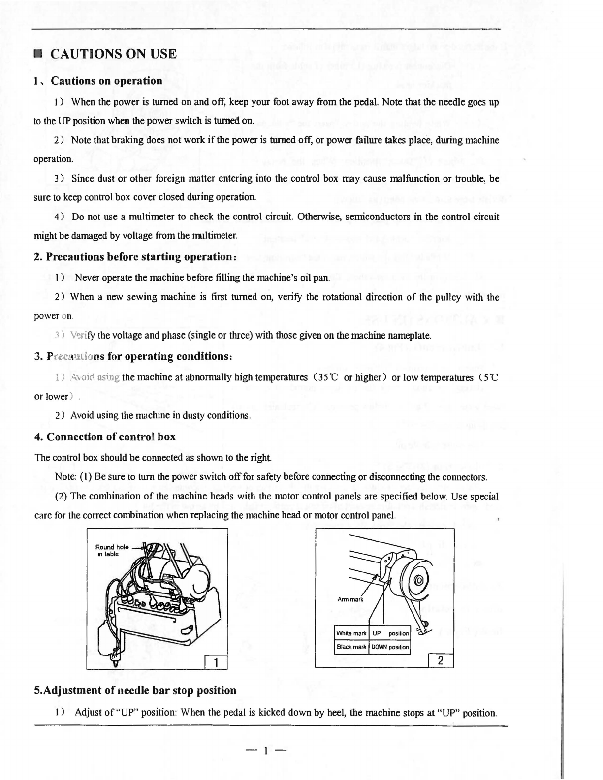
Connection
Note:
(2) The combination
for
the correct combination when replacing the machine head or motor control panel.
(I)
of
contro box
Be sure
to
turn the power switch
of
at
abnormally high temperatures (
as
shown
the machine heads with the motor control panels are specified below. Use special
or
three) with those given on the machine nameplate.
35
'C or higher) or low temperatures ( 5
to
the right.
off
for safety before connecting or disconnecting the connectors.
·c
INMe
mark
Black mark
S.Adjustment
I)
Adjust
of
needle
of"UP"
bar
stop position
position: When the pedal
is
kicked down by heel, the machine stops
-1-
UP
DOWN
pos1110n
position
at
"UP" position.
Page 4
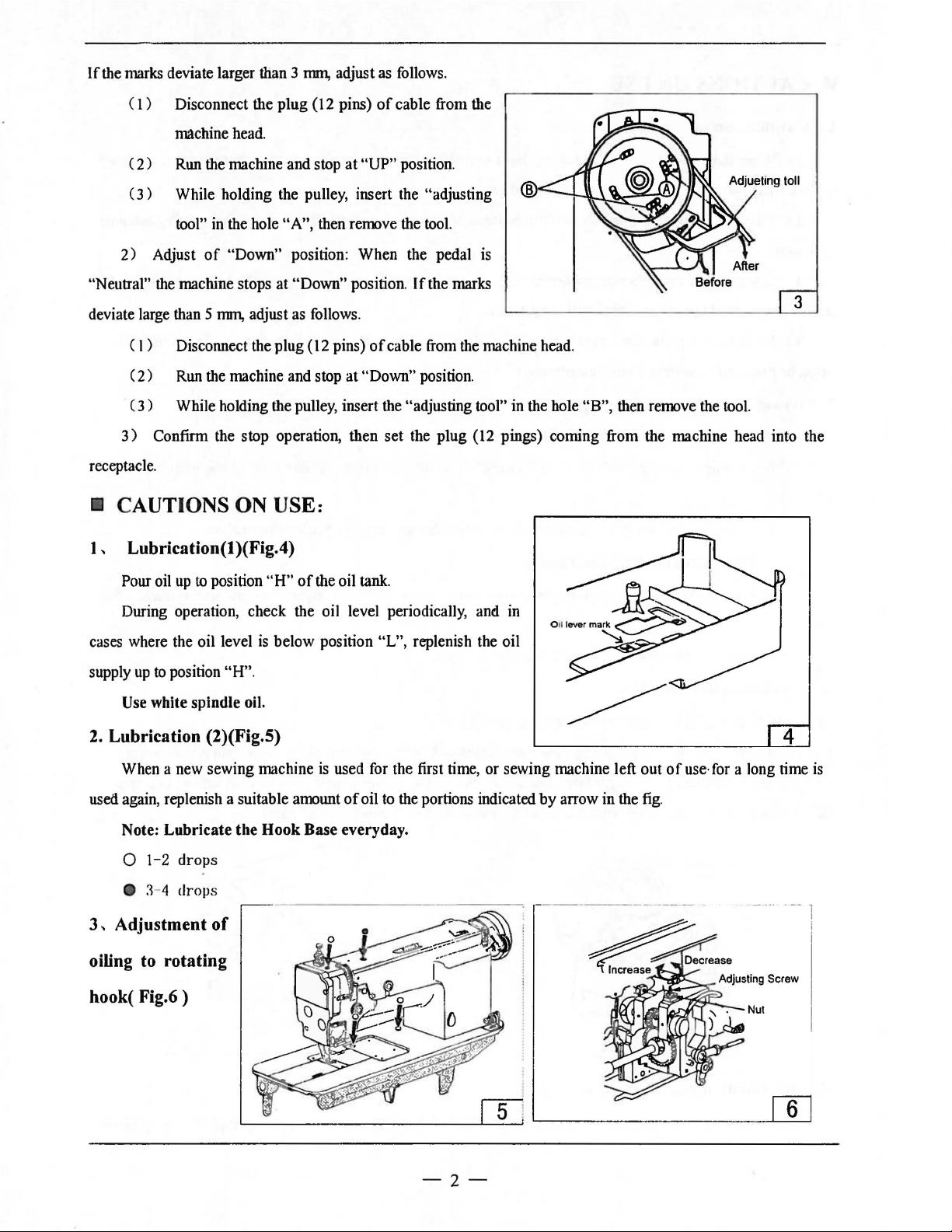
If
the marks deviate larger than 3 nnn, adjust
(
l)
Disconnect the plug (12 pins)
machine head.
(
2)
Run the machine and stop
(3)
While holding the pulley, insert the "adjusting ®
tool"
in
the hole "A", then remove the tool.
2)
Adjust
of
"Down" position: When the pedal is
at
as
follows.
of
cable from the
"UP"
position.
"Neutral" the machine stops at "Down" position.
deviate large than
(I
) Disconnect the plug (
(
2)
(
3)
3)
Confirm the stop operation, then set the plug (12 pings) coming from the machine head into the
receptacle.
•
CAUTIONS
5 nnn, adjust as follows .
12
pins)
Run the machine and stop
While holding the pulley, insert the "adjusting tool" in the hole "B", then remove the tool.
at
"Down" position.
ON USE:
If
the marks
of
cable from the machi
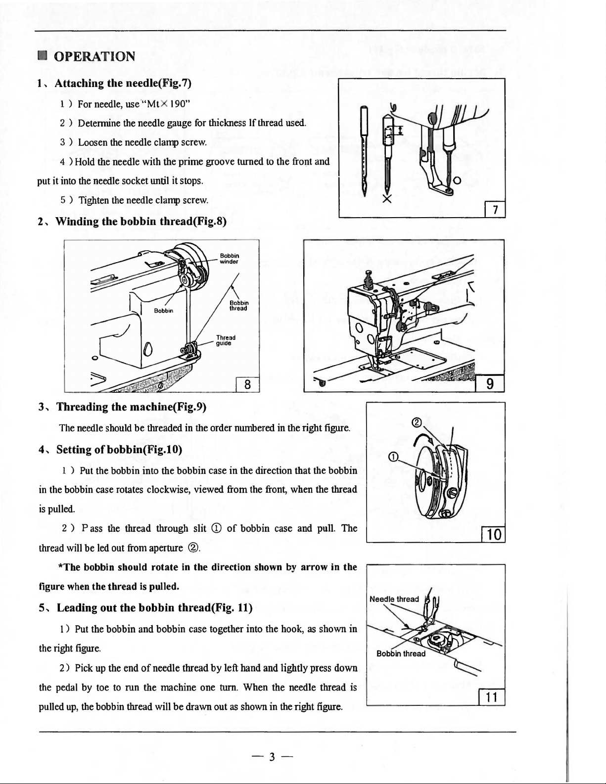
1 , Lubrication(! )(Fig.4)
Pour oil
During operation, check the oil level periodically, and in
cases where the oil level
supply
Use
up
to
position
up
to
position
white spindle oil.
"H"
"H"
of
the oil tank.
is
below position "L", replenish the oil
.
ne
3
head.
2.
Lubrication (2)(Fig.5)
When a new sewing machine
used again, replenish a suitable amount
is
used for the first time, or sewing machine left out
Note: Lubricate the Hook Base everyday.
0 1-2
e
3,
Adjustment
~
- 4
drops
drops
of
oiling to rotating
hook( Fig.6 )
of
oil
to
the portions indicated
-2-
by
arrow in the fig.
of
use· for a long time
is
Page 5
OPERATION
1 , Attaching the needle( Fig. 7)
1 ) For needle, use '
2 ) Determine the needle gauge for thickness If thread used.
3 ) Loosen the needle clamp screw.
4 ) Hold the needle with the prime groove turned
put it into the needle socket until it stops.
5 ) Tighten the needle clamp screw.
2,
Winding the
"Mt
bobbin
X 190"
thread(Fig.8)
to
the front and
7
9
3,
Threading the machine(Fig.9)
The needle should
4,
Setting ofbobbin(Fig.lO)
1 ) Put the bobbin into the bobbin case in the direction that the bobbin
in the bobbin case rotates clockwise, viewed from the front, when the thread
is
pulled.
Pass
2 )
thread will be led out from aperture
*The bobbin should rotate in the direction shown by arrow in the
tigure when the thread
5,
Leading
I ) Put the bobbin and bobbin case together into the hook, as shown in
the right figure.
2)
the pedal by toe
Pick
out
up
be
threaded in the order numbered in the right figure.
the thread through slit
CD
of
bobbin case and pull. The
®.
is
pulled.
the
bobbin
the end
of
to
run the machine one turn. When the needle thread is
thread(Fig.
needle thread
11)
by
left hand and lightly press down
<D
up,
pulled
the bobbin thread will
be
drawn out
as
shown in the right figure.
-3-
Page 6
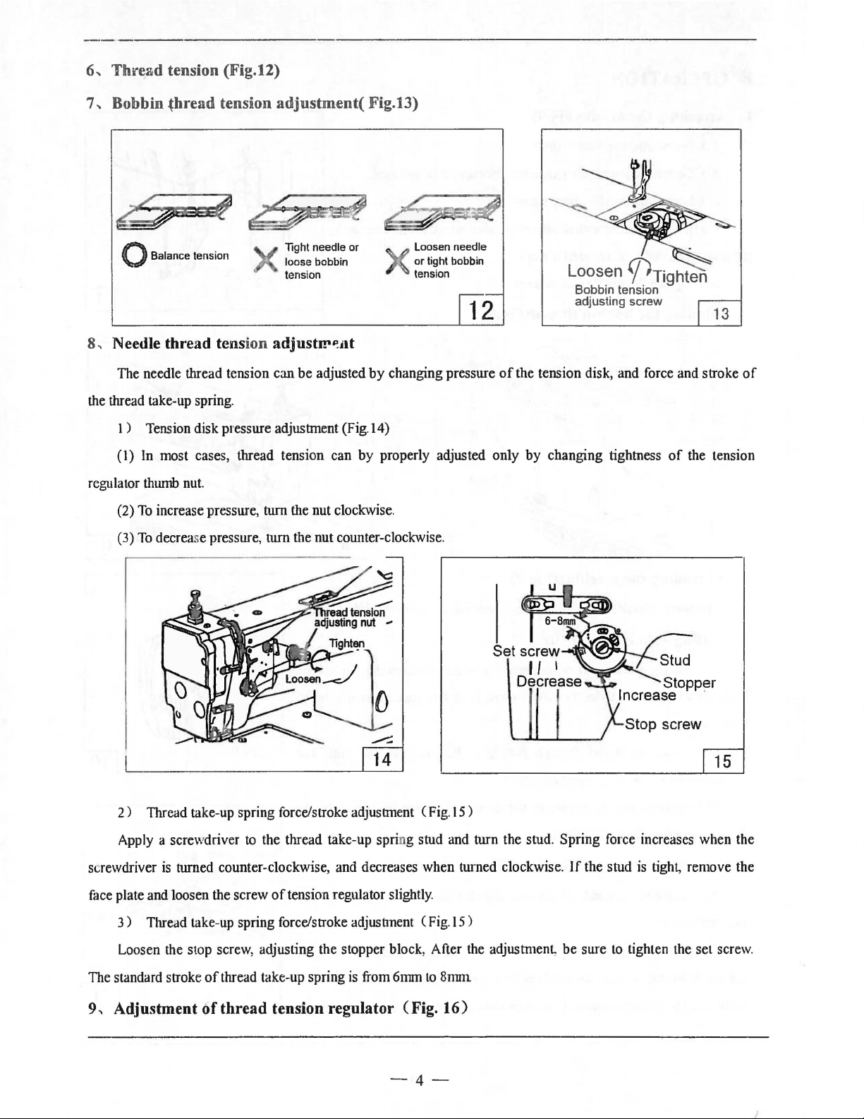
6..
Thread
tension (Fig.12)
7" Bobbin
0 Balance tension
8
..
Needle thread tension
The needle thread tension can
the thread take-up spring.
1 ) Tension disk presstrre adjustment (Fig.
(1) In most cases, thread tension can by properly adjusted only by changing tightness
regulator thmnb nut.
(2)
thread
To
increase presstrre, ttrrn the nut clockwise.
tension
adjustment(
Tight needle or
loose bobbin
tension
adjustl!'~dt
be
adjusted
.Fig.13)
Loosen needle
or
tight bobb in
tension
by
changing presstrre
l4)
Loosen
Bobbin tension
adjusting screw
of
the tension disk, and force and stroke
'J)Tighten
of
the tension
13
of
(3)
To
decrease pressure, ttrrn the nut counter-clockwise.
2)
Thread take-up spring force/stroke adjustment
Apply a scre\vdriver to the thread take-up spring stud and ttrrn the stud. Spring force increases when the
screwdriver
face plate and loosen the screw
3 ) Thread take-up spring force/stroke adjustment ( Fig.
is
ttrrned counter-clockwise, and decreases when ttrrned clockwise.
of
tension regulator slightly.
(Fig
. 15)
15
If
the stud is tight, remove the
)
Loosen the stop screw, adjusting the stopper block , After the adjustmen
The standard stroke
9,
Adjustment
of
thread take-up spring
of
thread
tension regulator (Fig.
is
from 6mrn
to
8nm1
16)
-4-
t,
be sure
to
tighten the set screw.
Page 7
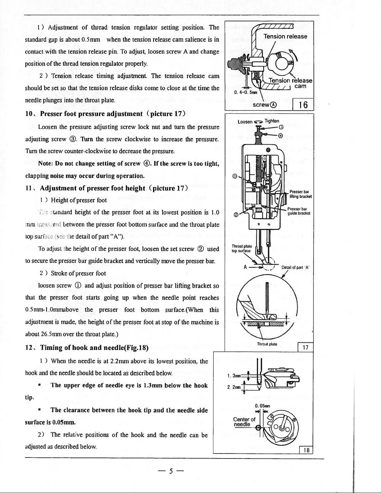
1 ) Adjustment
of
thread tension regulator setting position. The
standard gap
contact with the tension release pin.
position
2 ) Tension release timing adjustment The tension release
should
needle plunges into the throat plate.
10,
Presser foot pressure
Loosen the pressure adjusting screw lock nut and turn the pressure
adjusting screw
Turn the screw counter -clockwise
Note: Do not change setting
clapping noise may
11
, Adjustment
l ) Height
'i'.>'!
is
about 0.5mm when the tension release cam salience is in
To
adjust, loosen screw A and change
of
the thread tension regulator properly.
be
set so that the tension release disks come to close at the time the
®.
Turn the screw clockwise
occur
of
of
presser foot
~
tandard
height
adjustment
to
decrease the pressure.
of
screw
during
operation.
presser foot height
of
the presser foot at its lowest position is 1.0
(picture
to
@.
If
(picture
17)
increase the pressure.
the
screw is too tight,
17)
cam
Loosen
screw®
.;-:.
Tighten
1010.---<ID
mm 1
r.
eas mxi
top
surface (sec the detail
To
to
secure the presser
2 ) Stroke
loosen screw
that the presser foot starts going up when the needle point reaches
0.5mm-l.Ommabove the presser foot bottom surface.(When this
adjustment
about 26.5nnn over the throat plate.)
12,
Timing
1 ) When the needle
hook and the needle should
•
tip.
•
surface is 0.05mm.
between the presser foot bottom surface and the throat plate
of
part "A").
adjust the height
of
is
made, the height
of
The
upper
The
clearance
of
the presser foot, loosen the set screw ® used
bar
guide bracket and vertically move the presser bar.
presser foot
CD
and adjust position
of
hook
and
needle(Fig.18)
is
at 2.2mm above its lowest position, the
be
located as described below.
edge
of
needle eye is 1.3mm below
between
the presser foot at stop
the
of
hook
presser
tip
and
bar
lifting bracket so
of
the
needle side
the machine is
the
hook
Center
needle
Throat
0.0511111
of
plate
2)
adjusted
The relative positions
as
described below.
of
the hook and the needle can
be
-5-
18
Page 8
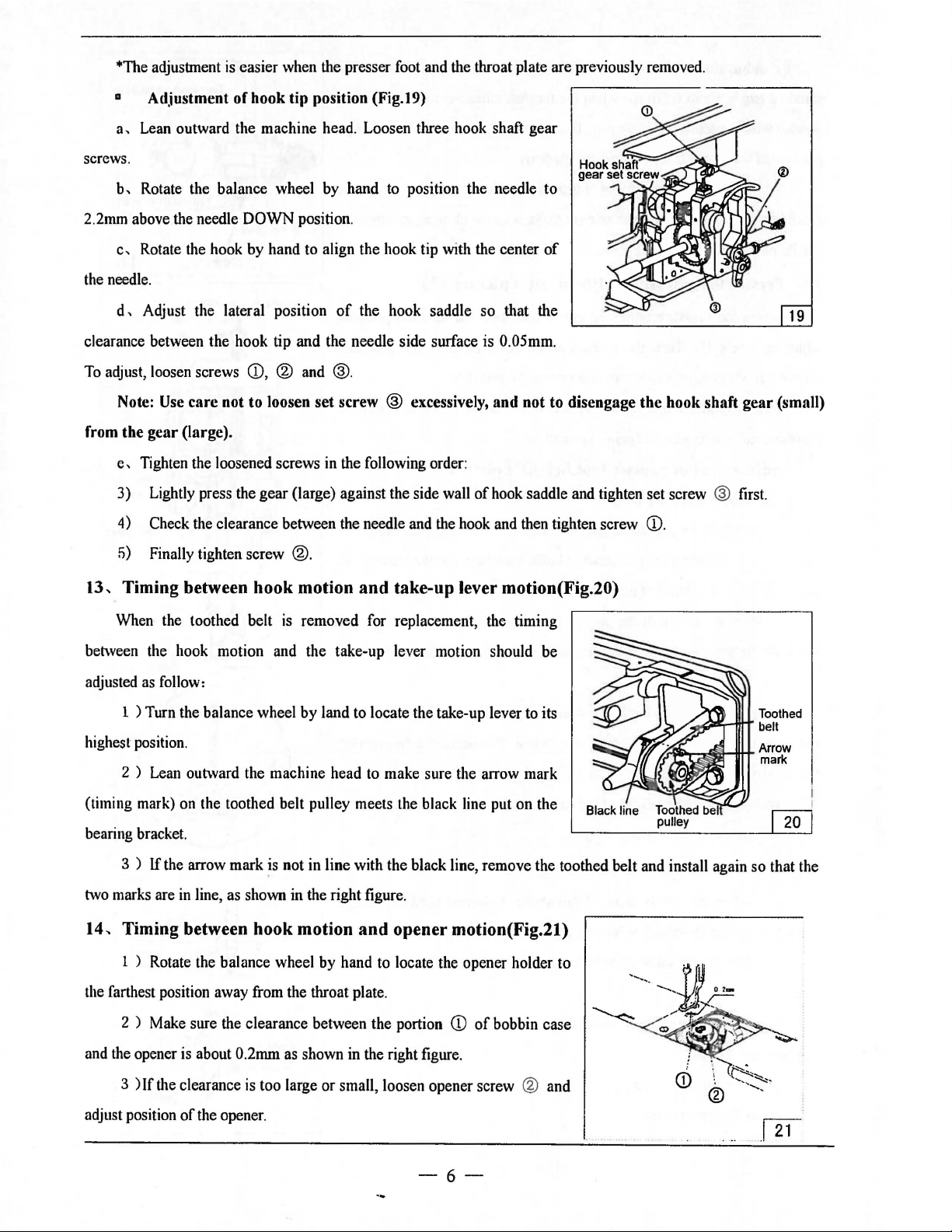
*The adjustment
is
easier when the presser foot and the throat plate are previously removed.
• Ad.iustment of hook tip position (Fig.19)
a,
Lean outward the machine head . Loosen three hook shaft gear
screws.
b,
Rotate the balance wheel by hand
2mm
2.
the needle.
clearance between the hook tip and the needle side surface is 0.05mm.
To
above the needle DOWN position.
c,
Rotate the hook by hand to align the hook tip with the center
d,
Adjust the lateral position
adjust, loosen screws
Note:
Use
care not to loosen set screw ® excessively, and not to disengage the hook shaft gear (small)
CD,
® and
of
®.
to
position the needle to
of
the hook saddle so that the
from the gear (large).
e,
Tighten the loosened screws
3) Lightly press the gear (large) against the side wall
in
the following order:
of
hook saddle and tighten set screw ® first.
19
Check the clearance between the needle and the hook and then tighten screw
4)
5)
Finally tighten screw
13, Timing between hook motion
When the toothed belt
between the hook motion and the take-up lever motion should be
as
adjusted
highest position.
(timing mark) on the toothed belt pulley meets the black line put on the
bearing bracket.
two marks are
follow:
1 ) Turn the balance wheel
2 ) Lean outward the machine head
3 )
If
the arrow mark
in
line, as shown in the right figure.
14, Timing between hook motion
l ) Rotate the balance wheel by hand to locate the opener holder to
®.
and
take-up lever motion(Fig.20)
is
removed for replacement, the timing
by
land to locate the take-up lever to its
to
make sure the arrow mark
~s
not in line with the black line, remove the toothed belt and install again so that the
and
opener motion(Fig.21)
CD
.
/ - ..GASr-11tT belt
Toothed
Arrow
mark
the
farthest position away from the throat plate.
CD
of
2 ) Make sure the clearance between the portion
and the opener is about 0.2mm as shown in the right figure.
3 ) If the clearance is too large or small, loosen opener screw
adjust position
of
the opener.
bobbin case
® and
-6-
Page 9
• ADJUSTMENT
OF
THREAD TRIMMER
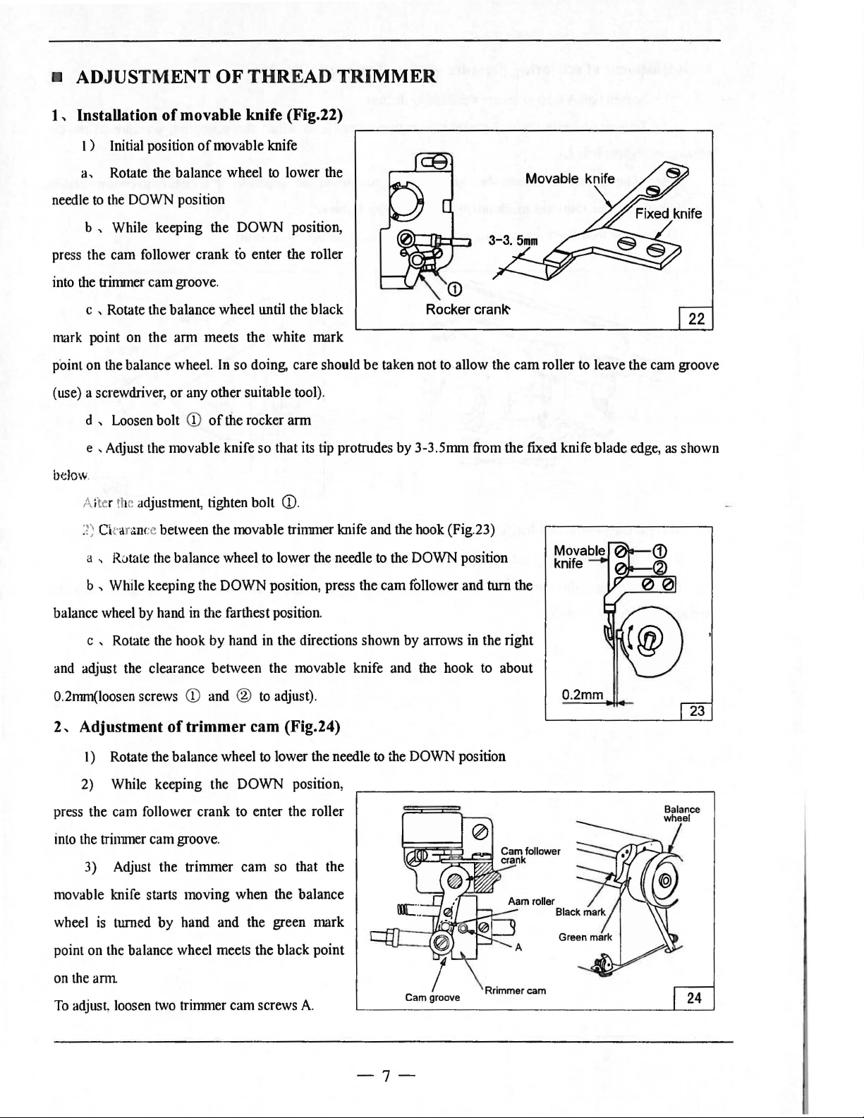
1 , Installation
l)
Initial position
a,
Rotate the balance wheel
needle
to
the DOWN position
b , While keeping the DOWN position,
press the cam follower crank to enter the roller
into the trimmer cam groove.
c , Rotate the balance wheel until the black
mark point on the arm meets the white mark
point on the balance wheel. In so doing, care should
(use) a screwdriver,
d , Loosen bolt
e , Adjust the movable knife so that its tip protrudes by 3-3.5mm from the fixed knife blade edge, as shown
btl
ow
.
Alter the adjustment, tighten bolt
of
movable knife (Fig.22)
of
movable knife
to
lower the
or
any other suitable tool).
CD
of
the rocker arm
CD.
Rocker
be
taken not to allow the
crank-
cam
roller to leave the cam groove
2) Ck anmcc between the movable trinnuer knife and the hook (Fig.23)
a , Rotate the balance wheel to lower the needle
b , While keeping the DOWN position, press the cam follower and
balance wheel by hand in the farthest position.
c , Rotate the hook by hand in the directions shown
and adjust the clearance between the movable knife and the hook to about
0.2nnn(loosen screws
2,
Adjustment
I) Rotate the balance wheel
2) While keeping the DOWN position,
press the cam follower crank to enter the roller
into the trinnner cam groove.
3) Adjust the trimmer
movable knife starts moving when the balance
wheel
is
turned
CD
and ®
of
trimmer cam (Fig.24)
by
hand and the green mark
to
adjust).
to
lower the needle
cam
so that the
to
the DOWN position
by
arrows in the right
to
the DOWN position
tum
the
0.2mm
point on the balance wheel meets the black point
on the
ann
To
adjust loosen two trimmer cam screws
A.
Cam groove
-7-
Page 10

3,
Adjustment
( 1 ) Loosen bolt A used to secure the fixed knife base.
(
2)
Turn fixed knife vertical position adjusting screw 8 to adjust the scissoring pressure. After the
of
scissoring pressure
of
thread
trimmer
(Fig.25)
adjustment, tighten bolt
Note:
The
over-torque to
(3) Move the movable trirruner knife to make sure threads are cut successfully.
4,
Sharpening the fixed knife(Fig.26)
If the fixed knife becomes dull, sharpen it as shown
A.
pressure
the
trimmer
should
mechanism,
be
adjusted
and
trimming
Fixed knife
base
A
B
as
minimum
failure.
in
the figure below.
as
possible. Excessive
pressure
causes
Since it
movable knife becomes dull.
is
impossible to sharpen the movable "knife, replacement with a new one is required when the
-8-
Page 11

A.ARM
BED
AND
ITS
ACCESSORIES
16
33323~
-9-
Page 12

A.ARM BED AND ITS ACCESSORIES
Fig.
No.
AOl
A02 H2400B2060
A03
A04
A05
A06 HA300B2170 Screw
A07 Il3200B2030
A08
A09
AlO H3200B2040
All
Al2
Al3
Al4
Al5
Al6
Al7
Al8
Al9
A20
A21
A22
A23
A26 H4813B!l001
A27
A28
A29
A30
A31
A32 HA300B:?.
A33
A34
A35
A36
I 37 H675GB8001 Thread cutter 1
t\38
Part
No.
H3000D2160
H3200B2060 Oil
1-1320082070
H2400B20MO
H3200B2050
H2400J2010 Oil
H2000B2010 Rubber plug
HA700B2060
H2400B2100 Thread guide
HA100E2150 Screw 2
HH415B7101
H6658B8001
HA100E2150 Screw 1
HAJOOB2070 Washer
HI-142787101
H2000M0090
H4913B8001 Needle
14491288001
H3200B20MO
H5015B8001
H4914B8001
HH411B8001 Needle plate
HI-141288001
HH413B8001
H4747B8
HA106B0673 Rubber plug 2
HA300B2160 Screw
l-13
20082020
H6762B8001
Screw
Spacer
guide plate 1
Thread guide
Screw 3
Ann
side cover (left)
'fbrend
take-up cover
cap 1
Ann
>'
ide cover (right)
Screw
Bobbin winder complete
Rubber ring
Thread guide complete
Cap 2
bar
supporter
Screw
Thread guide
Slide plate (Jell)
Cover
Screw
Needle holder
Scr<Jw
l90 Sere 2
Slide plate (right)
001
Face plate
Screw 2
Description
Pes.
2
1
I
11
1
1
(<ll13)
1
(<ll13)
1
2
1
SM11164(40)xlO
1
<ll35
1
SMll/64
<ll4.5x<IJ8x
1
1
1
2
2
l 3/32-5/
1
2
1
I
1
SM11/64(40)x6.5
3/32-1/4
1
(<ll19)
2
1
SM91
Ci4(40)X4
!l
Remarks
(40J
1
.5
xl()
-10-
Page 13

B.
THREAD
TENSION
1 2
MECHANISM
3 4
5 6 7
19 18
L
24
20
21
22
23
17
16
15
14
13
12
11
10
-11-
Page 14

B.THREAD TENSION MECHAN ISM
Fig.
No.
801
802
803
804
805
806
807
80!!
809
810
811
812
813
814
1315
816
817
818
819
820
821
822
8:!3 HA31080701
8:!4
Part No.
Thread
l-1322180687
HAI0680676 Screw I
.1-1322186820
HA300C2030 Screw
H3221B6810
H322180683
HAII2B0693
1-13221806!!4
HA71080671
H2504C0658
l-1324818221
H324818D21
H4804C8001 Screw I
H2504C0652
1-1200410067
H320082100
H322186819 Stopper
HH406C8001
HH407C8001
HA31080705 Thread tension
HA31080702 Tension releasing plate
HA60780068 Spring
HA3411D30!! Screw
guide I
Mounting plate I
Nut 2
Thread tension stud
TIU'ead
tension disc 2
Spring
Thumb nut I
Thumb nut
Thread Take-up spring
Plate complete
TIU'cud
tension stud
Screw I
Screw
TIU'ead
tension stud
Thread releasing pin
Thumb nut
Description
elise
Pes.
SM 9/64( 40) x6
2
SMIII6
SMII/64(40)x3
SMII/64(40)x14
I
I
I
I
I
SM9/64(40)x22
I
SM9/64(40)x7
SM9/64(40)x6.5
I
I
I
I
2
I
I
I
I
Remarks
4(40)x8
-
!2-
Page 15

C.THREAD
TAKE-UP
LEVER
MECHANISM
&
ARM
SHAFT
MECHANISM
1 2 5 7 8 6 9
10
11
12
13
14 15 16 17 18
25
26
-13-
Page 16

C.THREAD TAKE-UP MECHANISM & ARM SHAFT MECHANISM
Fig.
No.
COl
C02 H32422CI08
C03
C04
cos
C06
C07 H240SD0662
COB
C09 H32111D704
CIO
Cll
Cl2
Cl4
CIS
Cl6
Cl7
Cl8
Cl9
C20 H3204C06SI Arm shaft
C21
C22
C23
C24 HAIOOF2130
C2S
C26
C27
C28
C29
C30
C31
C32
C33
C34
C3S
C36
C37
C38
C39
C40
Part
No.
Oil
H240SD1122
HAI10D0672
H240SDIIII
H240SDI112
H24211D30S
H240SD0662
HA307C0662 Screw I
HAIOSD0662 Screw 1
HAIOOC2070 Screw I
HAIOOC2060 Screw
H240SD0664
H32111BI04 Felt 1
H3204BOOII Arm shaft bushing left (complete) I
HA30SE0662 Screw 2
HH404D8001
H320SC0661 Spring flange 3
HAII3F0684 Screw
H3207C0671 Pulley I
H3200C2030 Cog belt 1
H320SC1021 Pulley
HA104F06S4 Screw 2
H4931L8001 Machine pulley 1
HAIIOD0672
H4930L8001
HA700R0030
H4928L8001
HA700R0040
HA700ROOSO
HA700R0060
H007009300 Retaining ring C-type I
H320SJ0662 Ball bearing
HA300C2030
HA703R0067
HA703R006S
wick I
Thread Take-up guide bracket pin I
Screw
Thread Take-up lever I
Thread Take-up slide block
Plug I
Thread take-up crank pin I
Oil
wick I
Needle bar connecting link 1
Screw I
Thread releasing
Screw I
Screw 2
Speed command disk
Spacer A 2
Speed command disk F20 (up) I
SpacerB
Spacer
Stopper
Screw
Washer
Detector bracket
Description
cam
Fl1
(down)
Pes.
2.Sx240
SMIS/64{28)x 12
3
I
SMI/4{40)x6
SMI/4(40)x4
SM9/32(28)xiO
SM9/32(28)x
I
SMIS/64(28)xl4
I
I
SMIS/64{28)x8.S
I
SM IS/64(28)X6. 7
I
I
1
1
I
I
I
1
1
Remarks
13
-14-
Page 17

D.NEEDLE
BAR & PRESSER
28::-i
::~
25~
22
FOOT
MECHANISM
29
~30
16
7
8
9
6
-15-
Page 18

D.NEEDLE
BAR
& PRESSER FOOT MECHANlSM
Fig.
No.
DOl
D02 HD41708001 Bushing
D03
D04 HH406E8001
D05 H32111D504 Needle bar connecting
D06 H32111D604
D07 HD415D8001 Crank guide
D08 HAIOOC2190
D09
DID
011 HD41308001 Bushing
Dl2
Dl3
Dl4
Dl5
Dl6
Dl7
Dl8
Dl9
D20 HA300C2030 Screw
D21
D22
D23
D24
D25
D26 H2400GOI40
D27
028
029
030
031
Part
No.
H2405D0664 Screw
HH405E8001
HD41608001
HH417E8001
H620408001 Needle clamp
HA500C2030
HAIOOC2170
HD404D0651 Needle
HH407E8001
H3200E2020 Screw
HH408E8001 Bushing
HH409E8001 Presser bar position guide bracket
HH411E8001 Bracket
HH412E8001 Lever spring
HH413E8001 Presser bar
HH414E8001 Spring
HAI17H0692
H2400GOI60 Nut I
H2400G0150 Screw
HA70400657 Rubber plug
HE016L8001 Felt
HH416E8001
Washer
Rubber ring
Screw
Screw
Bell crank guide
Needle bar
Needle bar thread guide
Screw
Lining
presser
Nut
Screw
Pin I
Description
Pes.
3 SM 15/64(28)x
I
4
2
I
I SM9/64(40)x8.5
I
SMI1164(40)x8
2
I
I
I
I
I
SMI/8(44)x4.5
I
MTxl90
I
I
I/8(44)X9
I
1
1
SMII/64(40)x8
2
I
I
I
I
SMI/2X28
I
SM 112(28)x55
I
SMII/64(40)
SM11164(40)x48
I
I
I
16#
Remarks
14
-
16-
Page 19

E.
HOOK
SADDLE
MECHANISM
9
10
--------n
---------18
27
26
-17-
Page 20

E.HOOK SADDLE MECHANISM
Fig.
No .
EOI
E02 H320410021
E03 H320710661
E04 H320710066 Bushing 1
E05
EO'
E07
EOS
E09 H321531504
E10 H321531204
Ell
E12
El3
E14
E15 H320012020 Opener 1
E16
E17
E18
E19
E20 HAI05D0662
E21
E22
E23
E24
E25
E26
E27
E2l!
E29
E30
E31
Part No.
HH404F8001
H850417101 Hook complete I
H6906H8001 Spring
Hl!50518001
H320410656 Oil wick
H321531304 Ling
H32153l104
H2004J0067 Screw I
H3200l2030
H005008050 Spring washer 1
HA104G0658 Nut 1
H320410657
H321421204 Gear (small) 1
H320410653
H2013J0065 Washer
H320012050 Screw
H320410658
H320410659 Nut 1 SM3/16{28)
H005014050 Spring washer 1
HA305E0662
H321421104
HA307C0662
H320416510
H850618001
Hook saddle (right) I
Hook shaft bushing (upper) complete
Screw
Bobbin 1 B0-112(A)M
Bobbin case opener holder pin I
Screw 1
Bobbin case opener holder
Washer I
Screw
Screw 3
Hook shatl bushing (lower)
Screw 1
Screw
Gear (large)
Screw
Screw
Bobbin case
Description
Pes.
1
SM 15/64(28)x30
1
HSH-12-15M
1
2.5x)5
2
SM3/16
1
I
SM9/64
GBrf93
SM3/16(28)x14.5
1
SMJ/4
1
1
SMI/4(24)x23
1
SM3/16x(28)X43
GBrf955
2 SM15164 (
I
SMJ/4(40)x6
1
SM114(40)x6.5
1
1 CP-12C
(30)
(40
5
(40)
) x7
5
2X)
Remarks
(3)
x7.8
X4
X4.5
-18-
Page 21

F.
KNIFE
MECHANISM
(10)
15 16
17
19 20
21
22
.lJI.
-19-
Page 22

F.KNIFE MECHANlSM
Fig
.
No.
FOJ
F02 H4915J8001
F03
F04
F05
F06 H4925J8001
F07
F08 H4911J800J
F09
FlO
FJ
Fl2
Fl3
Fl4
Fl5
Fl6
Fl7
Fl8
Fl9
F20 HA710E0692
F21
F22
F23
F24
F25
F26
F26
F27 H4974K8001 Arm
F28
F29
F30
F31
F32
F33
F34
F35
F36
F37
F38 H4943K.8001
F39
F40 H4965K.800 I Set
F41
F42
Part No.
H492JJ8001
H4920J8001
1-!492418001
H69041800I
H4912J8001
H4913J8001
H4908J8001
I Hl-140408001
H4914J8001
H4922J8001 Cover (right)
H4914B8001 Screw 4
H4909J8001 Fixed blade 2
H4907J8001 Trimming knife holder
H4906J8001
H4905J80ul
H4932K8001
HAl 13F0684 Screw
H6904J8001 Bushing
H4979K8001 Solenoid complete
H4977K8001 Mounting plate I
H003008050 Nut
H4951K8001
H4951K.8001 Nut I
HAIIIG0683
H4981K8001
H4972K.8001
H4971K8001
H4970K.8001 Screw
H4967K8001 Screw
H4966K8001 Stopper
H41
1050160 Screw
H3205Gll14
H4957K7101 Vibrating crank complete
HAIOOH2080 Pin type
H2012N0652 Screw I
H4963K8001 Shat\ I
Lever
Screw
Roller
Knife pad (right)
Guide (right) I
Screw
Screw I
Move knife I
Screw 1
Screw
Rever~ing
Spring plate I
Bolt 2
Screw 2
Cam
Screw
Nut I
Screw
Holder
Screw
Lever
Screw
Spring 1
spring
plate 1
Description
Pes.
1
SM3/32
2
1
I
SM9/64
I
SM1/8
SM9/64
2 SM9/64
I
I
SM9/64
2
SMII/64
SM9/64
I
SMI/4 ( 40) X9.5
2
SMI5/64
2
I
I
2 GB/T6172.1 M5
SMII/64
SMil/64
I
I
SMI
I
SMil/64
I
I
I
SMil/64
3
SMII/64
I
GB'TXI9. 1 M5xJ6
2
M5 x5
2
I
I
SM ), 4 ( 24 ) X I
(56)
(40) >'9.5
(44)
(40)
(40)
(40)
(40)
(40)
(28)
(40)
(40)
1/64 C40J
(40)
(40J
C40J
Remarks
X .8
x9.2
x4.5
x4
X4
x12
x7
X8.5
x)2
x6.8
x6
x7
()
-20-
Page 23

F.KNIFE MECHANISM
Fig.
No.
F43 H4944K8001
F44
F45
F46
F47 H4939K8001 Bolt 1
F4H
F49 H4987K8001
F50 H4912K8001 Arm
rst
F52 H4905K8001
fo53
rs4
rss
F56
F57 HAIOOE2150
rss
Part No.
Screw
H4936KROOI
H3405D0663 Ball joint (right) I
H003002050 Nut (right) I
H4940K8001
H4913K8001 Bolt
H4980K8001
HA300B2170
Hl-140508001
HA700N0080
Hl-140608001
Screw 2
Nut (Jell) 1
joint
Boll
Screw
Holder 2
Screw
Bracket
Screw
Screw I
Screw
(Jell) 1
Description
Pes. Remarks
SMII/64
I
M5(0.5)X8.5
0Brf6170
M5(1ell)
SM15/64 (2H)
I
M5(0.5)x7.5
2
SMII/64
2
I
I
SMI5/64
SM
11/64
SM11164
1
(40)
x5.5
M5
xl2.5
(40)
x8
(:?.8)
xJ:?.
(40) X 10
(40)
-21-
Page 24

G.
LOWER
SHAFT & OIL
LUBRICATION
MECHANISM
31
30
29 28
2726
25
2423
-22-
22
21
20
19
18 17
16
Page 25

G.LOWER SHAFT & OIL LUBRICATION MECHANISM
Fig.
No.
GO!
002
003
004
005
006
007
008
009
010
Gil
012
013
014
015
016
017
018
019
t
i:!O
021 H320406510
02:! H3215K0693
023
024
025
026
0:!7 HA106B0676 Screw
G:!X
0:!9
030
031 H3200K0170 Holder
032
033
GJ4 H3:!16K0070 Oil pipe & wick complete
035
036
037
03X H3200H2010 Lower shall
039
Part
No.
HA300C2030 Screw
H3200K0170 Holder 1
H32422C208
H32175B304 Felt
H3209K0066 pipe & felt complete
H3200K0200 Holder 1
HA300B2170 Screw
HA7311C306 Screw
H3200H2060
H3208H0661 Ball bearing
H3208H0662 Bushing
HAII203012
HAI0500662
H3230K0751 Screw
H3230K0752 Bushing
Illi404H71
H3215K0696
H110012070
HIIOOI2090
HI 10012110 Spring holder
H3215K0692 Filter
H3215K0694 Screw
H3215K4011 Base plate complete
H3:!15K0695
H3:!311
HA300B2130 Screw
HG805J8001
H3211K0068 Oil reservoir complete
H32132B204 Oil wick
H3200KOI60
HA100E2150 Screw
H3204B0032 Lower shall bushing .Jctl (complete)
H3204B0043 Lower shatl bushing right (complete)
Pipe 1
Bearing holder
Ring
Screw
01
Lower shatl bushing middle (complete)
Pipe
Pin
Spring
Screw
Screw
Holder
0606
Holder
Pipe
Holder
Description
Pes.
4 SMI!/64{40)x8
2
1
SMII/64(40)x9
3
SM9/64(40)x7
3
1.
1
1
I
SMI/4(40)x4
2
2 SMI1/64(40)xiO
I
1
1
1
1
1
SM 1/8( 44)x4.8
I
SM9/64(40)x5
I
1
SM9/64(40)x7
1
1
1
SM9/64(40)X6
1
3
6
SMII/64(40)x5.5
1
1
1
2
1
3
SM11164{40)x10
2
1
1
1
Remarks
-23-
Page 26

H.
ACCESSORIES
22~
19------------r
2
13~
~
3
-4
7
12
11
10
-24-
9 8
Page 27

H.ACCESSORIES
Fig
.
Part
No
.
HOI
HO:!
HOJ
1-
104
1-
105
1106
1107
l-108
1109
HIO
III I H3213L
I-II:!
1-
113
1114
1-115
1-1
16
1-117
HI!! HA300J2210 Screw driver( small)
1119
1-120
121
11-
122
No.
I-ID40400651 Needle
I-16907H!!OOI
H3200L0020 Vibration preventing rubhcr 2
l-13:!00
L0030 Vibration preventing rubber
HA307J0067
HA I OOJ2120
HA300J2070 Screw driver(large) I
HA104J0653 Washer I
HAI04J0652
I-
IAIOOB2150
1-145001-1:!0
HA I OOJ21
H3218L0681 Felt I
H3200LOI30 Oil can
HA200J:!030 Cotton :;land
HA300J2200 Screw driver(middle)
HAIOOJ21
HH404l7101 Belt cover (complete)
HA300J22XO
HA704S0654 Adjusting plute for speed commund disk
Bobbin
Hinge complelt:
Magnet block lhr
Screw
Rubber plug I
Oil
rc:;'-.,-
OM
I
I 0 V-bclt I
Vit~yl
XO
10
Oiler I
Screw
voir I
cover
Description
re~crvoir
Pes.
3
3
:!
:!
I
I
I
I
I
I
I
I
2
I
MTx
i90
16#
SM5/ l
<l(:!X)x I:!
<l>l
:U!
M44
SM 15/64 (
Remarks
28)
X
l!
-25-
Page 28

SHANGHAI HUIGONG
N0.3
SEWING MACHINE FACTORY
ADD: 1418, Yishan Road, Shanghai,
China
Zip Code: 201103
Overseas
Business: TEL: 86-21-64853303 FAX: 86-21-64854304
E-mail: highlead@online.sh.cn http://www .highlead.com.cn
The
descri
ption
covered
in this
manuuli~
subject
tu
change for imp rov
emen
t of the c
ommod
ity without notice
ZO
4.11. Printed
 Loading...