

Page 1

Purchasing
HIGHLEAD
GC20698 Series
Dept
Copy
•
Long
Material Lockstitch Sewing Machine
Arm
Version,Compound-feed,Heavy
Instruction
Parts
Catalog
Manual
SHANGHAI HUIGONG
N0.3
SEWING MACHINE FACTORY
Page 2
CONTENTS
PRECAUTIONS
PREPARATION
l. Power cable connection --------
2.
Connection
3.
Adjustment
CAUTIONS
I. Oiling (
2.
Oiling (2)
3.
Oiling condition ---------------·
4.
Adjustment
5.
Cautions on operation ----------·
BEFORE
FOR
of
control
of
needle
ON
USE
l)
------------
-----------------·--------------------------------------------------4
of
oiling to rotating hook -----------------------------------------------------------5
STARTING
OPERATION
box
----------------------------------------------------------------------3
bar
stop position ---------------------------------------------------------3
OPERATION
1.
Installation
2.
Winding
3. Selection
4.
Threading
5.
Adjustment offeed (stitch) length and stitch reversing (touch-back) -
6.
Setting
7.
Threading
8.
Tension adjustment
9. Balance
10.
Needle thread tension ------------
l l. Adjustment
12.
Timing between rotating hook motion
13.
Adjustment
of
needles---
of
bobbin thread
of
thread ---------------------------
of
needle threads ---------------------------------------------
of
bobbin -------------------------------------------------------------------------------7
of
bobbin threads
of
thread tension ----------------
of
presser foot pressure
of
feed dog height
----------------------------
of
bobbin threads ----------------------------------------------------------9
OPERATION
·---
----
------------------------------------------------------4
---------
----------------------------------------------------------------5
---------------------------
----
---
----------------
------------------------------------and
_________________________
- -------------------------------------4
--
·--------
---------------
needle
motion
-------------------------------------- l
--------------------------------2
---------------------------------------------5
--
------
--
-
--------------6
-----------------------------------6
-----------------------6
--------------------
------------------------------------
---------------
--------------
--------------------------------------9
\_
_____________________________________
---
----------------
--
--------------9
----------------9
-------7
-----8
---
--9
10
14.
Relationship between rotating hook
15.
Relationship between hook motion and opener
16.
Relationship between needle motion
17.
Safety clutch device --------------------------------------------------------------------------
18.
Upper
feed
adjustment (needle side)'-----------------------
19.
Outside presser foot and inside presser vertical stroke adjustment -
20.
Adjustment
21.
Installation
22.
Adjustment
23. Adjustment
24
. Adjustment
25.
Sharpening
26.
Adjustment for change
SPECIFICATIONS
of
forward/backward stitch
of
movable knife ------
of
thread trimmer
of
needle threads tension release assembly -
of
scissoring pressure
of
fixed knife----------
of
needle
-----------------------------------------
motion
cam
--------------
of
------------------------------------------------
to
needle distance---
and take-up lever motion
motion
and
feed
dog motion ------------------------------------
length ---
---
---------
movable
----
------
---
---------------- ----
knife and fixed knife
---
·-
----
---
--------·-
---------
--
------
--
----
------
----
----------·- - - - ---
-------------
--
--
------------------------14
---
---------
---
--
----
--
----
--
- --
----------
--
--------------
---
---
-------
----------
---
---------
---------
--
·----
---
--------17
--
----
------
---
---
-----
---
--
11
11
11
12
13
14
14
15
16
16
17
18
Page 3

PARTS
CATALOG
I . Ann bed its accessories
2.
Thread tension regulator mechanism
3.
Ann shaft mechanism
4.
Upper shaft & presser foot mechanism --;-
5.
Needle bar & thread take-up lever mechanism
6.
Stitch regulator mechanism
7.
Lower shaft & feed rock shaft mechanism
8.
Hook saddle mechanism
9.
Knife mechanism ( I ) -------------------------------------------
10.
Knife mechanism
11
. Touch back mechanism & detector mechanism
12.
Accessories
GAUGE
PARTS
-----------
LIAT
---------------------------------------------
-----------------------------------------------------------
---
------------------------------------------------,---------------------
(II)
--------------------------------
--
----------------------------
---------------------
------------------------------------------------
------------------------------------------------
---
-------------------------------------------
-------------------------------------------------
----
---
---------------------------
------------------
----
---
-------------
------------
--
---------------------------
---
----
19
21
24
26
29
--
32
34
37
39
41
44
46
48
Page 4
PRECAUTIONS BEFORE STARTING OPERATION
1.
Safety precautions
I) When turning the power on, keep your hands and fingers away from the area around/under the
needle and the area around the pulley.
2) Power must be turned
3) The power must be turned
adjusting the machine,
4) Avoid placing fingers, hairs, bars etc. near the pulley,
when the machine
5) Do not insert fingers into the thread take-up cover, under/round the needle, or pulley when the
is
in
machine
If
a belt cover, finger guard, and/or eye guard are installed,
6)
these safety devices :
2.
Precaution before Starting Operation
I)
If
the machine's oil pan has an oil sump, never operate the machine before filling
2)
If the machine
3) When a new sewing machine
the power on. (the pulley should rotate counterclockwise when viewed from the pulley.)
4)
Verify the voltage and (single or three) phase with those given on the motor nameplate.
operation.
is
off
when the machine
off
before tilting the machine head, installing
or
when replacing.
is
operation. Injury could result.
lubricated by a drop oiler, never operate the machine before lubricating.
is
first turned on, verify the rotational direction
is
not used,
or
when the operator leaves his/her seat.
or
removing the
"V"
belt, bobbin winder pulley, or motor
do
not operate the machine without
it.
of
the pulley with
"V"
belt,
3. Precaution for Operating Conditions
I) Avoid using the machine at abnormally high temperature (35°C
Cor
lower). Otherwise, machine failure may result.
°
in
2) Avoid using the machine
3) Avoid using the machine in areas where too much electrical noise, resulted from the
high-frequency welder and others,
dusty conditions.
is
generated.
or
higher)
or
low temperature (5
-1-
Page 5
PREPARATION
FOR
OPERATION
~-----------------------------,
Operation
overall view
sewing machine
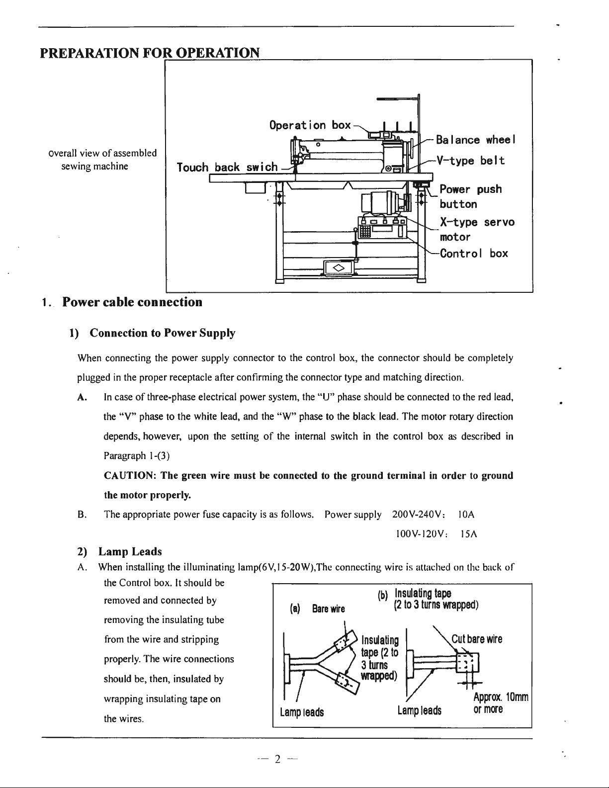
1 .. Power cable connection
1)
of
assembled
Connection to Power Supply
When connecting the
plugged in the proper receptacle after confirming the connector type and matching direction.
A.
In
case
of
the
"V
" phase
depends,
power
three-phase electrical power system, the
to
the white lead, and the "
how
eve
r,
upon the setting
Power
push
button
X-type servo
motor
Control
supply connector to the control box, the connector should be completely
"IJ"
phase should be connected to the red lead,
W"
phase to the black lead.
of
the internal switch in the control box as described
The
motor rotary direction
box
in
Paragraph 1-(3)
CAUTION:
the motor properly.
B. The appropriate power fuse capacity
The
green wire must be connected to the ground terminal
is
as follows. Power supply
2) Lamp Leads
A. When installing the illuminating lamp(6V, 15-20W),
the Control box.
removed and connected by
removing the insulating tube
from the wire and stripping
properly.
should be, then, insulated by
wrapping insulating tape on
the wires.
The
It
should be
wire connections
(
a)
Lamp
leads
in
order to ground
200V
-240V: I 0A
I00V-120V: 15/\
Thc
connecting wire is attached on the back
(b)
Bare
wire
Insulating
(2
to 3 turns
tape
wrapped)
lns~ating
tape
(2
to
3
turns
wrapped)
Lamp
leads
of
- 2 -
Page 6
CAUTION: The power switch must be Turned
off
before connecting the lamp.
B. When the illuminating lamp
shown
control box will be possibly burned out.
in
CAUTION: The illuminating lamp must not be connected with any heater, such
3) Rotary direction
It
is
possible to change the rotary direction
bottom left side
switch. The built-in lamp in the internal switch
facing to the motor pulley, and on when rotating clockwise. The rotary direction has been set to
counterclockwise as facing to the motor pulley, matching with the machine prior to shipping
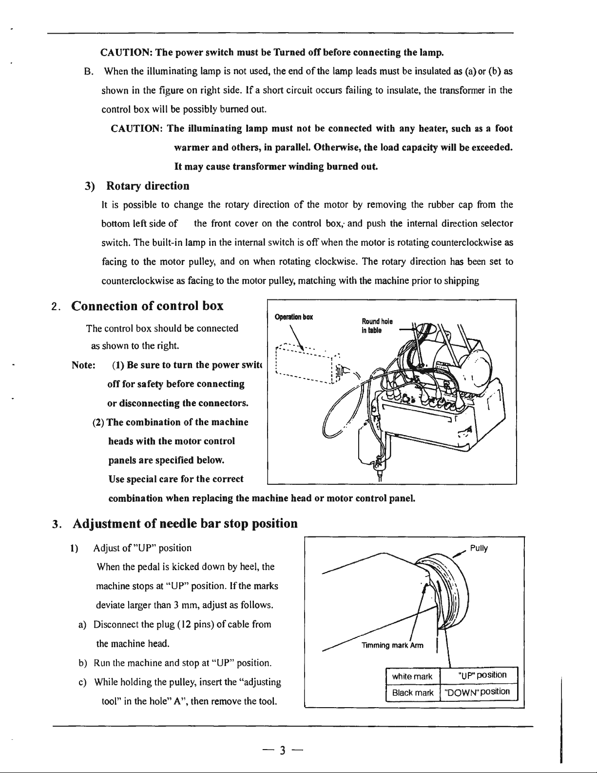
2. Connection
The control box should be connected
as shown to the right.
the figure
on
warmer and others,
It
may cause transformer winding burned out.
of
of
control box
is
not used, the end
right side.
the front cover on the control box; and push the internal direction selector
If
a short circuit occurs failing to insulate, the transformer in the
in
parallel. Otherwise, the load capacity will be exceeded.
Operation
of
the lamp leads must be insulated as (a)
of
the motor by removing the rubber cap
is
off
when the motor
box
Round
In
table
is
rotating counterclockwise as
hole
or
as
from
(b)
as
a foot
the
Note: (1) Be sure to turn the power swih
off
for safety before connecting
or disconnecting the connectors.
of
(2) The combination
the machine
heads with the motor control
panels are specified below.
Use special care for the correct
combination when replacing the machine head or motor control panel.
3. Adjustment
1) Adjust
When the pedal
machine stops at
deviate larger than 3 mm, adjust as follows.
a) Disconnect the plug (12 pins)
the machine head.
of
of
needle bar stop position
"UP"
position
is
kicked down by heel, the
"UP"
position . If the marks
of
cable from
b)
Run
the machine and stop at
c) While holding the pulley, insert the "adjusting
tool"
in
the hole" A", then remove the tool.
"UP"
position.
-3-
while mark "UP" positi
Black
mark
"DOWN" positi
on
on
Page 7
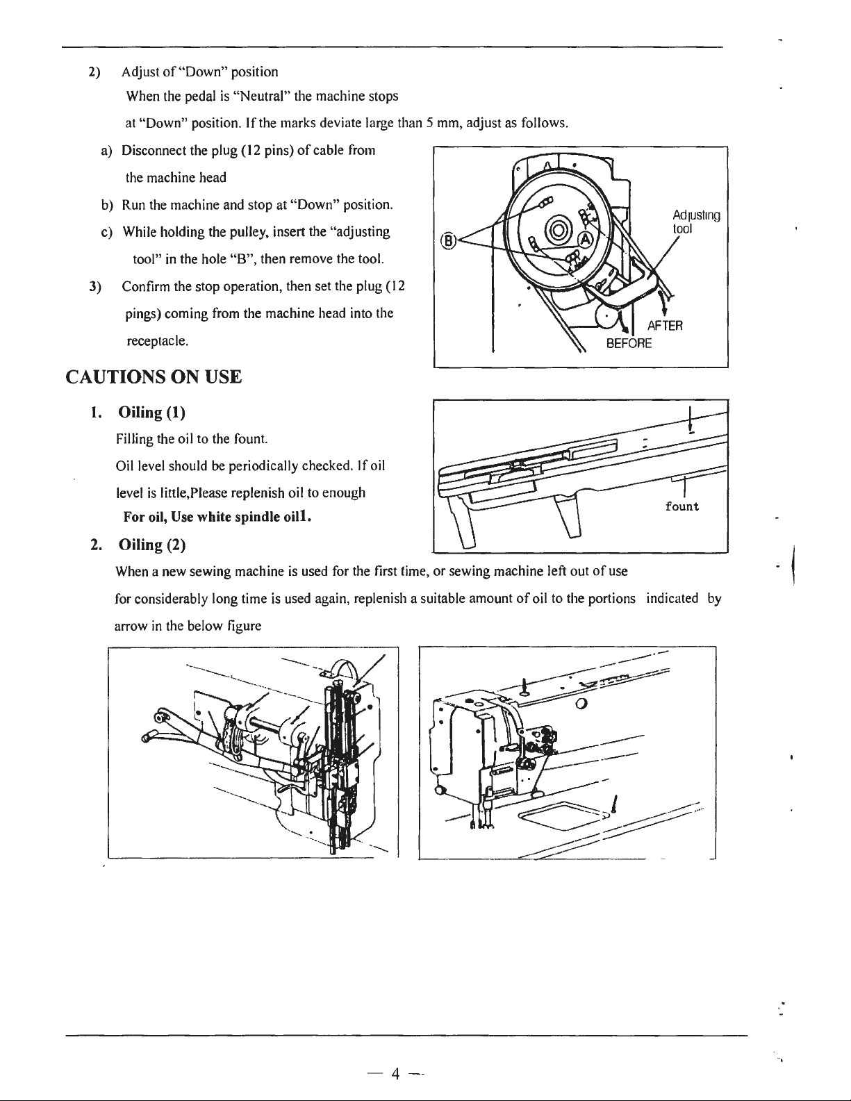
2) Adjust
When
at
"Down" position. If the marks deviate
a)
Disconnect
the
machine
b)
Run
the
While
c)
tool"
of
"Down" position
the
pedal
is
"Neutral" the machine stops
the
plug (
12
pins)
of
cable
head
machine
holding
in
the hole "B", then remove the tool.
and
stop at "Down" position.
the
pulley, insert the "adjusting
large
from
than 5
mm,
adjust
as
follows.
3) Confirm the stop operation, then set the plug (
pings) coming
receptacle.
from
the machine
head
CAUTIONS ON USE
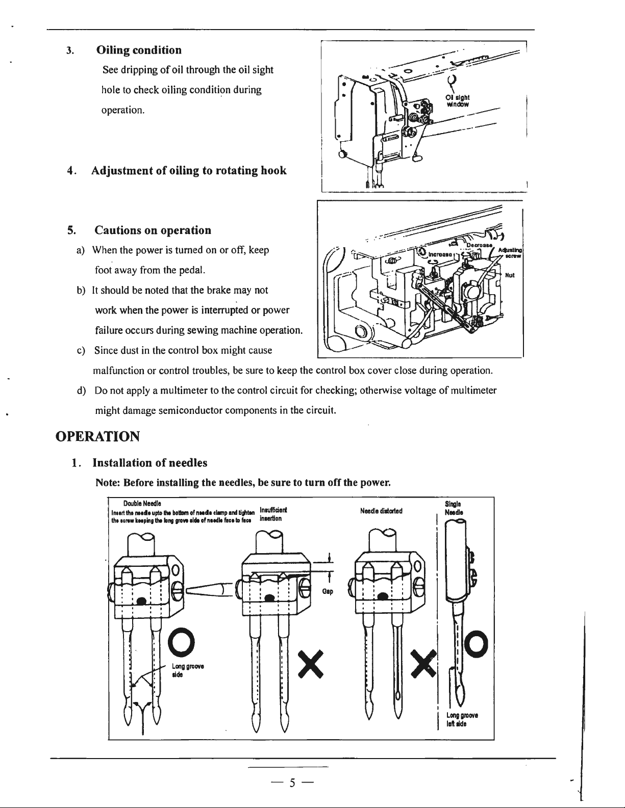
1.
Oiling (1)
Filling
the
oil
to
the
fount.
Oil
level
should
level
is
little,Please replenish
For oil, Use white spindle
2. Oiling (2)
When a new
for
considerably long time
arrow
in
the
be
periodically checked. I foil
oil
oill.
sewing machine
below figure
is
is
used
to
enough
used
for
again, replenish a suitable amount
----~
into
the
the
first
12
time,
or sewing machine left out
of
of
use
oil
to
the portions indicated
. I
by
- 4 -
------
Page 8
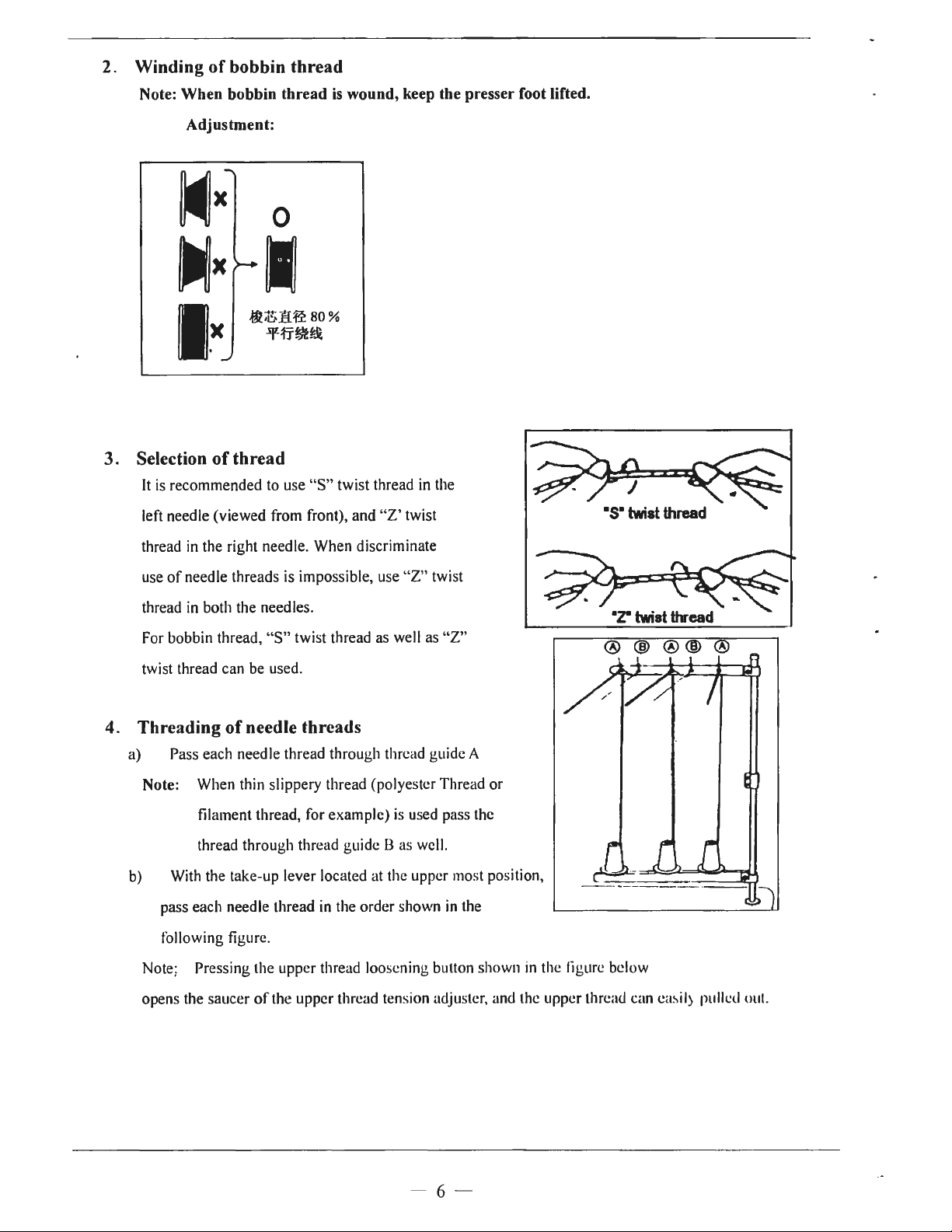
3.
Oiling condition
See dripping
hole to check oiling condition during
operation.
4. Adjustment
Cautions on operation
5.
a) When the power
foot away from the pedal.
b)
It
should be noted that the brake may not
work when the power is interrupted
failure occurs during sewing machine operation.
c)
Since dust
of
oil through the oil sight
of
oiling to rotating hook
is
turned
in
the control box might cause
on
or
off, keep
or
--·--
ICl9W
Nul
power
malfunction
d) Do not apply a multimeter to the control circuit for checking; otherwise voltage
might damage semiconductor components in the circuit.
or
control troubles, be sure to keep the control box cover close during operation.
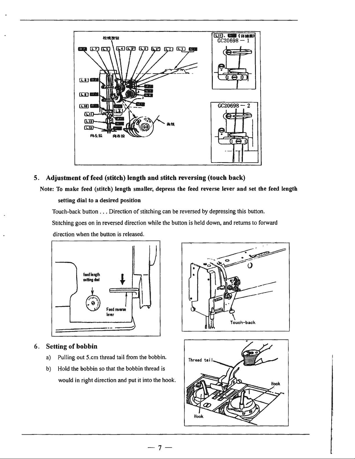
OPERATION
1. Installation
Note: Before installing the needles, be sure to turn
Double
lnutl
lhl
1crew
lh•
Needle
1111cl1
kNping
of
needles
upto
lhl
lhl
long
bollllm
grow
of
tide
nNclt
of
clamp
n1tdll
flee
and
ID
ti~
flee
~nlllfficieri
111Nr1lon
off
the power.
Needle
dillarled
0
Long
gro1111e
tide
X
of
multimeter
Sil'lle
Needle
I
!O
I
I
- 5 -
Long
groove
leftlide
Page 9
2. Winding
Note: When bobbin thread
of
bobbin thread
Adjustment:
is
wound, keep the presser foot lifted.
3. Selection
It
is recommended
left needle (viewed from front), and
thread in the right needle. When discriminate
use
thread in both the needles.
For bobbin thread,
twist thread can be used.
4. Threading
a) Pass each needle thread through thread guide A
Note: When thin slippery thread (polyester Thread
b) With the take-up lever located at the upper most position,
pass each needle thread in the order shown
of
thread
to
use
"S"
twist thread in the
"Z'
twist
of
needle threads is impossible, use
"S"
twist thread
of
needle threads
filament thread, for example) is used pass the
thread through thread guide B
as
well as "
as
"Z"
well.
twist
Z"
in
the
or
following figure.
Note; Pressing the upper thread loosening button shown in the figure
opens the
saucer
of
the
upper
thread tension adjuster, and the upper thread can easil) pulled out.
- 6 -
below
Page 10
uJI1, -
GC20698-
CiHIIII
1
5. Adjustment
Note:
To
make feed (stitch) length smaller, depress the feed reverse lever and set the feed length
setting dial to a desired position
Touch-back button
Stitching goes on in reversed direction while the button is held down, and returns
direction when the button is released.
GC20698-
of
feed (stitch) length and stitch reversing (touch back)
...
Direction
of
stitching can be reversed by depressing this button.
2
to
forward
f11d
lenvth
selling
dill
k
~
6. Setting
a) Pulling out 5.cm thread tail from the bobbin.
b) Hold the bobbin so that the bobbin thread is
of
bobbin
would in right direction and put it into the hook.
-
-----
---
- 7 -
Page 11

7. Threading
a) Put the hook into the bobbin case
of
bobbin threads
and press
The
the bed .
b)While holding the
by left hand, rotate the hand-wheel
one turn by right hand.
By pulling up the needle threads,
as shown
will be lifted. Each combination
thread and needle thread should be aligned
down
the latch
thread end should be left on
two
in
the figure, the bobbin threads
CD
.
needle threads
of
bobbin
and led backward .
- 8 -
Page 12
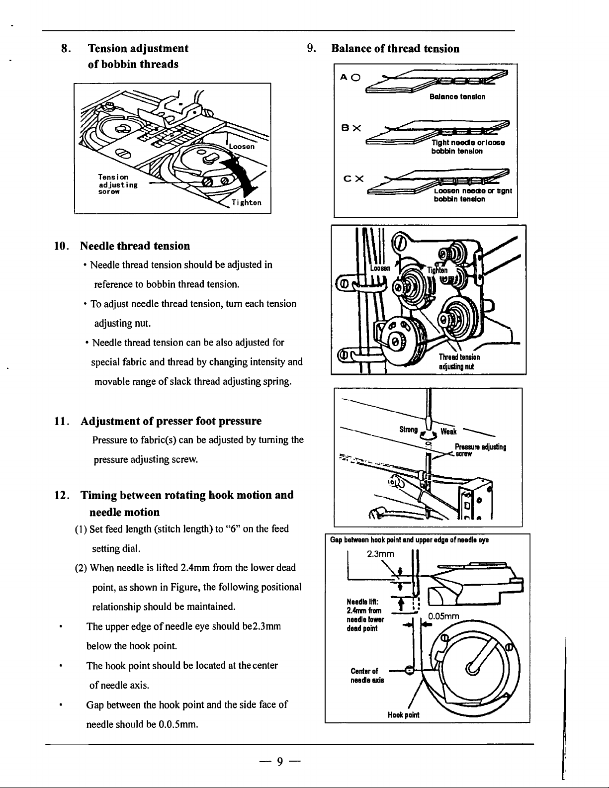
8. Tension adjustment
of
bobbin threads
9.
Balance
of
thread tension
Tension
adjusting
SOl"8W
10. Needle thread tension
• Needle thread tension should be adjusted in
reference to bobbin thread tension.
To
adjust needle thread tension, tum each tension
•
adjusting nut.
• Needle thread tension can be also adjusted for
special fabric and thread by changing intensity and
of
movable range
slack thread adjusting spring.
BX
2:::~
'~ht
C X /
,
Balance
bobbin
~:;..;?
~n
bobbin
tension
I I
1;?
neecle orloose
tension
neeae
or
tension
ogn1
11. Adjustment
Pressure to fabric(s) can be adjusted
of
presser foot pressure
by
turning the
pressure adjusting screw.
12. Timing between rotating hook motion and
needle motion
(I)
Set feed length (stitch length) to
setting dial.
(2) When needle is lifted 2.4mm from the lower dead
point, as shown
in
Figure, the following positional
relationship should be maintained.
of
The upper edge
needle eye should be2.3mm
below the hook point.
The hook point should be located at the center
of
needle axis.
Gap between the hook point and the side face
"6"
on the feed
of
------
Strang O Weak
--------9
~"i-:-
..
~ . ,i><.screw
- .
:._
.....:•.
Gap
betwean
haak
paint
and
upper
Needle
lift:
2.4nmfram
needle
lower
dead
paint
Center
af
needleuis
edge
----
Pressure
af
needle
adjusting
eye
needle should be 0.0.Smm.
-9-
Page 13
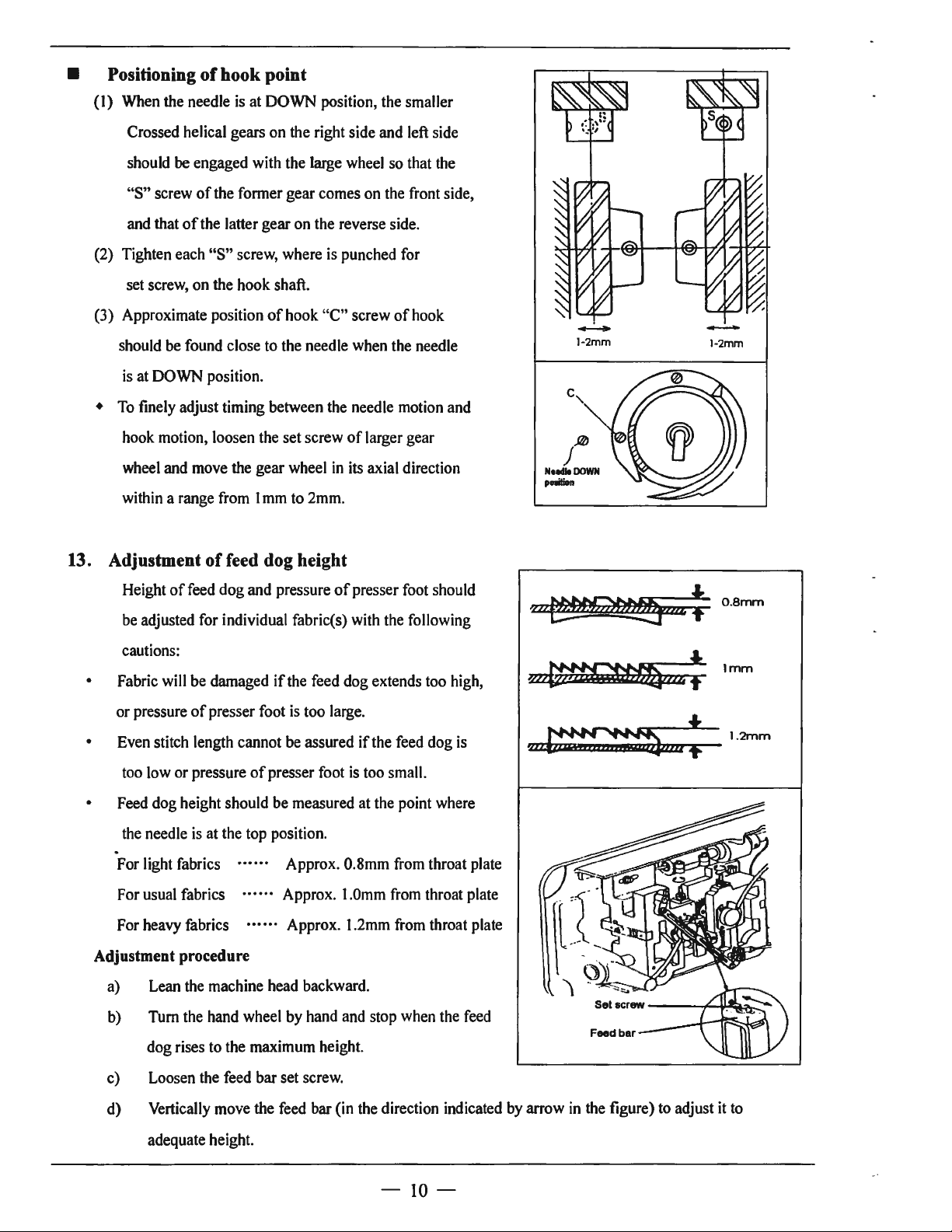
• Positioning
(I)
When the needle
-Crossed helical gears on the right side and left side
should
"S"
and that
(2) Tighten each
set screw, on the hook shaft.
(3) Approximate position
should be found close to the needle when the needle
is at DOWN position.
To
finely adjust timing between the needle motion and
•
hook motion, loosen the set screw
wheel and move the gear wheel
within a range from I mm to 2mm.
of
be
engaged with the large wheel so that the
screw
of
of
the latter gear on the reverse side.
hook point
is
at DOWN position, the smaller
the fonner gear comes on the front side,
"S"
screw, where is punched for
of
hook
"C"
screw
of
hook
of
larger gear
in
its axial direction
-
l-2mm
j,@
N1.U.DOWN
poeition
-
1-2mm
13. Adjustment
Height
be adjusted for individual fabric(s) with the following
cautions:
• Fabric will be damaged
or pressure
• Even stitch length cannot be assured
too low or pressure
• Feed dog height should be measured at the point where
the needle is at the top position .
of
feed dog height
offeed
dog and pressure
if
of
presser foot is too large.
of
presser foot
of
presser foot should
the feed dog extends too high,
if
the feed dog
is
too small.
.
For light fabrics
For usual fabrics
For heavy fabrics
Adjustment procedure
a) Lean the machine head backward.
Approx. 0.8mm from throat plate
Approx. 1.0mm from throat plate
Approx. 1.2mm from throat plate
is
0.
8mm
Imm
b) Tum the hand wheel by hand and stop when the feed
dog rises to the maximum height.
c) Loosen the feed bar set screw.
d) Vertically move the feed bar (in the direction indicated
adequate height.
-
IO-
by
arrow
in
the figure) to adjust
it
to
Page 14
e) After the adjustment, tighten the feed bar set screw.
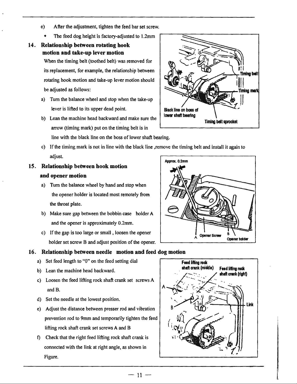
• The feed ~og height is factory-adjusted to
14. Relationship between rotating hook
motion and take-up lever motion
When the timing belt (toothed belt) was removed for
its replacement, for example, the relationship between
rotating hook motion and take-up lever motion should
be adjusted as follows:
a) Tum the balance wheel and stop when the take-up
lever is lifted
b) Lean the machine head backward and make sure the
arrow (timing mark) put on the timing belt is in
line with the black line on the boss
c)
If
the timing mark is not in line with the black line ,remove the timing belt and install it again to
adjust.
to
its upper dead point.
of
15. Relationship between hook motion
and opener motion
t .2mm
lower shaft bearing.
App-ax.
0.2mm
Timing
belt
sprocket
a) Tum the balance wheel by hand and stop when
the opener holder is located most remotely from
the throat plate.
b) Make sure gap between the bobbin case holder A
and the opener
c)
If
the gap is too large
holder set screw
b) Lean the machine head backward.
c) Loosen the feed
and B.
d) Set the needle at the lowest position.
e) Adjust the distance between presser rod and vibration
prevention rod to 9mm and temporarily tighten the feed
is
approximately 0.2mm.
or
small , loosen the opener
Band
adjust position
Ii
fti
ng rock shaft crank set screws A
of
the opener.
A
Opener
Scl'IIW
Opener
hdder
lifting rock shaft crank set screws A and B
f)
Check that the right feed lifting rock shaft crank is
connected with the link at right angle, as shown in
Figure.
-
11
-
Page 15
g)
If
the connection
cover, loosen screw C and move the right link to connect
the right feed lifting rock shaft with the link at right angle.
is
not at right angle, remove the back
h) After the completion
screws
A,
Band
• At this time make certain that needle can enter the
feed dog needle hole at the center
of
adjustment, fully tighten the
C.
of
the hole.
I
I
-,--l""T"-==---
I
Needle rod
Vibration
prevention
rod
Feed
shaft
lifting
crank
rock
(righl)
. I
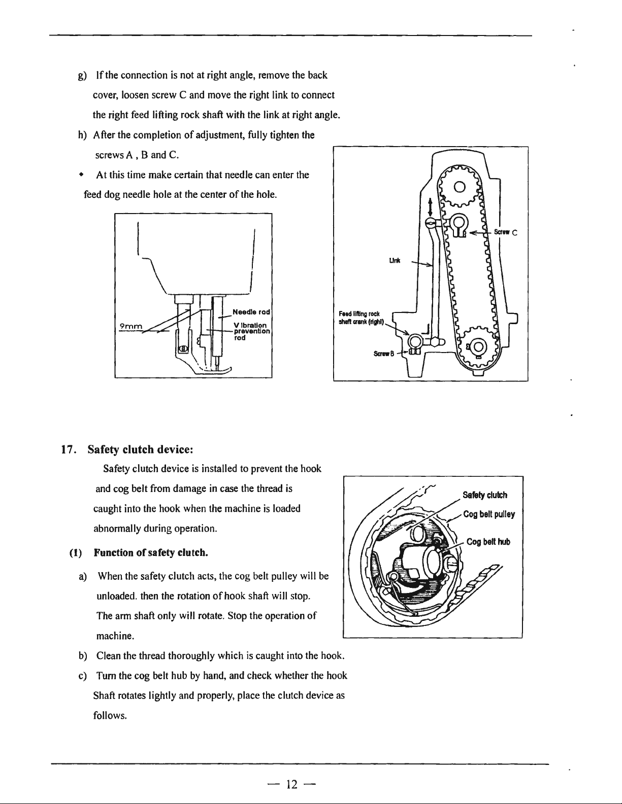
17. Safety clutch device:
Safety clutch device
and cog belt from damage
caught into the hook when the machine
abnormally during operation.
(1) Function
a) When the safety clutch acts, the cog belt pulley will be
unloaded. then the rotation
The arm shaft only will rotate. Stop the operation
machine.
b) Clean the thread thoroughly which
c) Turn the cog belt hub by hand, and check whether the hook
Shaft rotates lightly and properly, place the clutch device as
follows.
of
safety clutch.
is
installed to prevent the hook
in
case the thread
of
hook shaft will stop.
is
caught into the hook.
is
loaded
is
of
-
12
-
Page 16
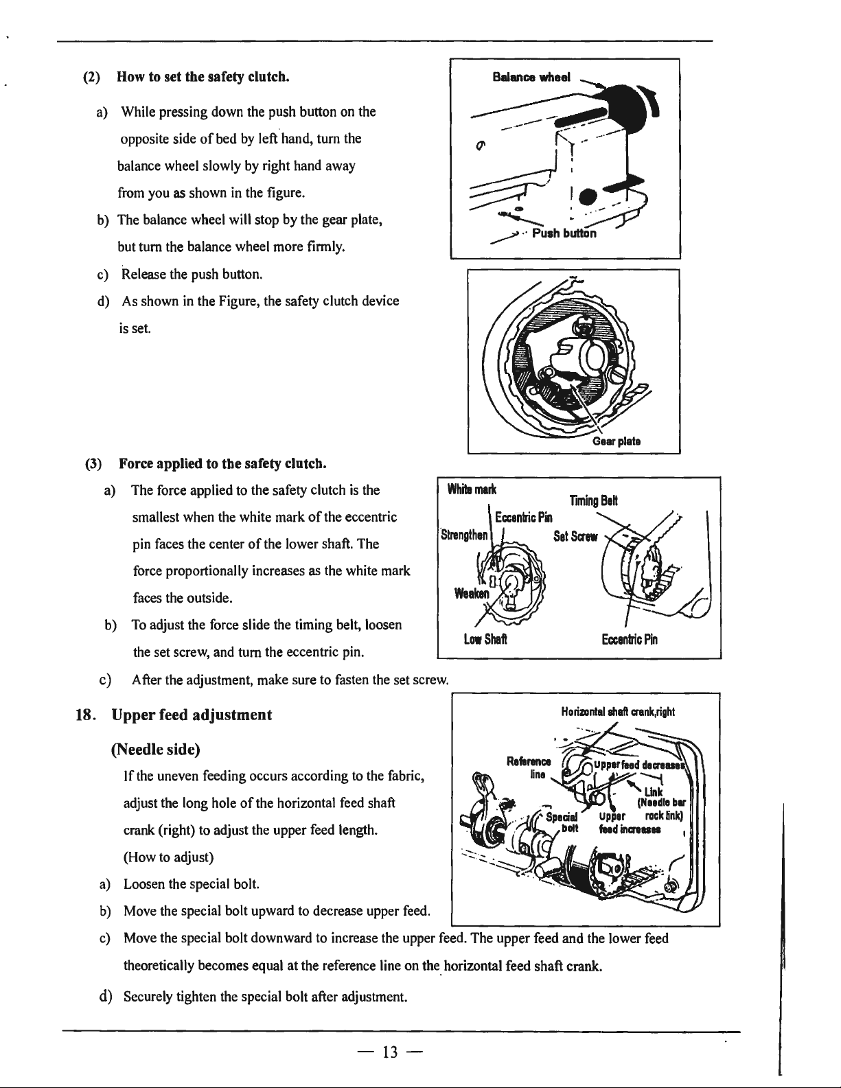
(2)
How
to
set the safety clutch.
a) While pressing down the push button on the
opposite side
balance wheel slowly by right hand away
from you
b) The balance wheel will stop by the gear plate,
but
tum
c) Release the push button.
d) As shown in the Figure, the safety clutch device
is set.
(3)
Force applied
a) The force applied to the safety clutch
smallest when the white mark
pin faces the center
of
bed by left hand, tum the
as
shown
the balance wheel more finnly.
in
the figure.
to
the safety clutch.
of
the lower shaft. The
of
the eccentric
is
the
White
mark
Eccentric
·
strengthen
Pin
Sat
TmingBett
Screw
force proportionally increases as the white mark
faces the outside.
b) To adjust the force slide the timing belt, loosen
the set screw, and tum the eccentric pin.
After the adjustment, make sure to fasten the set screw.
c)
18.
Upper feed adjustment
(Needle side)
If
the uneven feeding occurs according to the fabric,
of
adjust the long hole
crank (right) to adjust the upper feed length.
(How to adjust)
a) Loosen the special bolt.
Move the special bolt upward to decrease upper feed.
b)
c) Move the special bolt downward to increase the upper feed.
theoretically becomes equal at the reference line on the_ horizontal feed shaft crank.
the horizontal feed sha
ft
Low
Shaft
Horizontal
The
upper feed and the lower feed
Eccentric
lhaft
c:rank,right
Pin
d) Securely tighten the special bolt after adjustment.
-
13
-
Page 17

19. Outside presser foot and inside presser vertical stroke adjustment
When fabric with large elasticity
of
thickness
(movable range)
adjusted as follows:
Adjustment
a) Loosen the special bolt.
b) The vertical strokes
c) maximum when the crank rod
d) The vertical strokes becomes minimum when the nut
is
moved downward and set.
e) After the adjustment, fully tighten the special bolt.
The verticai strokes
•
fabric changes, the vertical stroke
of
the presser feet should be
of
the presser feet become
of
the presser feet can be adjusted within a range from 6mm to 2mm .
is
sewn, or when
is
moved upward and set.
20. Adjustment
Screwing the pin that connects the link
the tolerance
of
between the stitches. Screwing the pin
of
back-sewing with the crank
Specillbol
of
back-sewing (down) can adjust
in
clockwise can increase the stitch
of
forward
sewing; otherwise, the stitch
21. Installation
(1)
Installation
a.
Tum the balance wheel and lower the needle bar to the lowest position.
b.
Push the cam follower crank so that the cam roller enters into the thread trimmer cam groove.
c.
Tum the balance wheel until the black mark point on the arm meets the white mark point on the
balance wheel. Set the cam follower crank at this position with a screwdriver temporarily preventing
the cam roller coming out from the cam groove.
d.
Loosen the thread trimmer rocking crank clamp bolts A and
e.
Adjust the movable knife so that the movable knife end slant portion protrudes
0-0.5
mm
of
of
from the fixed knife, as shown
of
back-sewing
movable knife
movable knife
will
be increased.
B.
in
Figure and tighten the bolts A and
B.
-
14
-
Page 18

Thread
~a_.--r~
(2)
Gap between movable knife and bobbin case holder stopper
trimmer
rocking crank
a. Tum the balance wheel by hand until needle reaches the
Lowest position.
b. With the needle at the lowest position, depress cam follower
crank,
tum
the balance wheel until the movable knife reaches
Monable
knife
the extremity
c. Manually rotate the inner hook
of
its stroke.
in
the direction indicated
by
--.i1~-Approx
arrow in Figure and adjust gap between the movable knife
and the inner hook stopper to about 0.5 mm (the screws A and B should
22.
Adjustment
a.
Turn the balance wheel
b.
Maintaining the needle position, depress the cam follower crank and put the cam roller into the
groove
c.
Turning the balance wheel
of
of
thread trimmer
by
hand until the needles reach the lowest position.
thread trimmer cam.
by
cam
hand, _adjust the thread trimmer cam so that the movable knife starts
moving, when the green mark point on the balance wheel comes
be
loosened for this adjustment).
in
line with the black mark point on
the arm.
• To adjust, loosen two thread trimmer cam clamp screws
Cam
follower
A.
Green
mark
point
0.2
mm
Thread
trimmer
cam
15
-
Black
point
mark
Page 19

23.
Adjustment
of
needle threads tension release assembly
a. Tum the balance wheel by hand until the needles reach the lowest position.
b. Maintaining the needle position, depress the cam follower crank and put the cam roller into the groove
of
thread trimmer cam.
c. Turning the balance wheel
by
hand, adjust the thread tension release cam so that the
~nsion
when the white mark point on the balance wheel comes in line with the black mark point on the arm.
To
adjust, loosen two tension release cam clamp screws A.
d.
Opening degree
convex portion
e. Make fine adjustment by loosening the nut
f.
Loosen the nut D and make the outer casing approach rightward to increase the opening value.
of
tension disc should be adjusted with the tension release roller B mounted on the
of
thread release cam, as shown
in
Fig.To adjust, loosen the screws C and draw the wire.
D.
White
perk point
CID
Cam
follower
Thread
tenson
lever
'-....
disc close
I
trimmer
ScrewC
Nut
D
of
movable knife and fixed knife
24.
Adjustment
Thread
cam
of
scissoring pressure
a. Loosen the fixed knife bracket clamp bolt A.
b.
Turn the vertical position adjusting screw B to adjust meshing pressure and then righter the hexagon
socket head cap screw A.
Note:
Since excess pressure causes large
torque to the thread trimming mechanism
and trimming failure, adjust it so that
thread can be trimmed with minimum
Fixed kni
bracker
fe
pressure.
c. Move the movable knife and check that
the thread can
be
sharply trimmed.
Hexacon
cap
screw
socket
A
head
Vertical
position
adjustinc
screw
B
-
16
-
Page 20

25.
Sharpening
of
fixed knife
When the knives dull, the fixed should
be sharpened as illustrated in Fig.
it
is
Since
replace
26.
Adjustment for change
(I)
Replace the throat plate, feed dog and needle clamp.
very difficult to sharpen the movable knife,
it
with a new one when it dulls.
(Since the throat plate and feed dog are special parts designed
for thread trimming machine, be sure to use those specified
of
neecile-to-needle distance
by
us.)
(2) Lean the machine
head backward.
(3) Loosen two connecting
A
link clamp bolts
J.
( 4) Remove the spring
M.
Screw
(5) Loosen the hook bracket
clamp screws A and B and
Connecting
link
adjust gap between each
needle and hook.
(6) When the needles and
hooks have been adjusted,
install the spring
M.
Bolt J Stopp r
pin F Thread trimmer
--
rockmi:i crank
D
$crew
B
(7) Contact the rocking cranks
C and D to the stopper pins E and F and tighten the connecting link clamp bolt
(8) Turn the balance wheel by band until the needles reach the lowest position.
J.
Cam follower
crank
Thread trimmer
cam
(9) Loosen the nuts G and
(
10)
Depress the cam follower crank K and adjust the connecting rod L so that the cam roller can
smoothly enter the groove
of
(11) Adjustment
i.
ii.
Push the cam follower crank K so that the cam roller enters into the cam groove.
Turn the connecting rod
the cam groove and the cam roller
H.
of
thread trimmer cam.
Land
adjust the clearance between the cam roller and the cam
groove surface L as small as possible, and tighten the nuts G and H.
iii. Push the cam follower crank K again and check that the cam roller enters into the thread
trimmer cam groove smoothly.
-
17
-
Page 21

SPECIFICATIONS
-I
Model
Number Single-needle Double-needle Single-needle
Application Heavy material
Max. sewing speed
Stitch length
Thread take-up
lever stroke
Needle-bar stroke 36(mm)
Presser-foot stroke
Vertical stroke
upper feed
Needle No.
of
GC20698-1
GC20698-2
16(mm) by Leg
DPX17
GC20698-1-D
1800(rpm)
0,..._,9(mm)
74.5(mm)
2,..._,6(mm)
#23
GC20698-2-D
Double-needle
8(mm) by hand
Hook
Thread take-up
lever
Stitch adjusting
system
Lubrication system Manual lubrication
Clutch motor 370W Servo motor 550W
Needle
gauge
Note: +
Motor
Standard
Special 3.2 4 4.8 8
Some
those listed above.
materials, gauge sizes, and/or sewing conditions may require specifications other than
(Horizontal full-rotating) Large
Slide lever
Dial
6.4(mm)
9.5 12.7
16
19
25.4(mm)
+ Feed dog, throat plate, rotating hook, bobbin case and bobbin should be those designed for thread
timer.
+ Bobbin should be
of
high quality free from deformation.
+ This specification
is
subject to change for machine improvement.
-
18
-
Page 22

A.ARM BED AND ITS ACCESSORIES
-19-
Page 23

A.ARM BED AND ITS ACCESSORIES
I I
-
Fig.
No.
A0I
A02
A03
A04
A05
A06
A07
A08
A08
A09
AIO
All
Al2
Al3 H3219B0067
Al4
Al5 H4722B8001
Al6
Al7
Al8 H4725B8001 Thread guide I I
Al9
A20
A21
A22
A23
A24
A25
A26
A27
A28
A29
A30
A30
A31
A32
A33
A34
A35
A36
A37
A38
A39
Part No. Description
HA300B2090 Rubber plug
I-IA300B2170
1-14716B8001
1-14717B8001
1-14715B8001
1-14718B8001
1-12000B2010
H4919B8001 Side cover (right)
H4719B8001 Side cover (right) I
HA700B2060 Screw 2
1-12400B2100
HA307B0673 Rubber plug
H2000M0080 Cap 2
1-13200B2170
H4723B8001 Spring I I
1-14724B8001
H3200B2100 Screw I I
HA300B2190
H3200B2120 Screw
H3000D2160 Screw I I
H4726B8001
H4727B8001 Face plate I I
H2400B2080
H2400B2070 Thread guide (upper) I
H4730B8001 Guide mounting plate I I I I
H2400B2060
1-13200B2060
H4911B8001
H5015B8001 Cover I
H7007D7101
H7014D7IOI
1-14912B8001
H4913B8001 Supporter
H4915B8001 Cover
H4914B8001 Screw 2 4
H4916B8001
H4742E8001 Screw
H4751B8001
Screw
Oil
guard plate
Thread take-up cover
Rubber plug
Side cover (left)
Rubber plug
Thread guide I I
Slide plate complete I
Screw
Screw I I
Plate I I
Screw 2 I
Thread guide (middle)
Screw
for
oil
Plate
Oil
guard
Cover I
Bobbin complete
Down-lead complete
Screw
Pin
Tension releasing plate
guard I
00
1.0 1.0
°' °'
0
N N
u u
0
2 2
15
I I
I I
I
I I
I I I I
I I
I
2
I
I I
I I
2
I
Cl
N
00
0
0
15
I I
I
-
00
1.0 1.0
°'
0 0
N
u u
0 0
2 2
15
I I
I I
I I I
I I
I I
I
2
2 2
I I
I
2
2 2
I
I I
I I
I I
I I
I I
2
I
I I
I I I
I
2
2 2
I
I I
I
I I
I
I I
I
I
2 2
I
I I
2
I
Cl
N
00
°'
N
15
I
I
I
I
I
I
I
I
I
I
I
SMI
1/64
q,13
q,13
1/64
SMI
SM13/64
SMl/8
SM9/64
1/64
SMI
SM9/64
SM9/64
SM3/16
SM
1/4
SM9/64
1/64
SMI
Remarks
(40)
(40)
02)
(44)
x3
(40)
(40)
06) x6.5
(40) x6.5
(28)
< 24) , 9
<
40)
(40)
x8
x8
x4.8
x6.5
x8
xii
x6
~6
-
20-
Page 24

B.THREAD TENSION REGULATOR MECHANISM
8 9
14
15
16
so
49
\
I
\
I
J.
27
3
35
3
-
21
-
Page 25

B.THREAD TENSION REGULATOR MECHANISM
.....
N
I
Fig.
No.
801 H32218681 I
802 H322183142 Tension releasing plate I
803
804
805
806
807 H4707C800!
808 H007013050
809
BIO HA300C2030
Bil
812
813
814
815
816
817 H322180684 Thread tension spring I 2 I
B18
B19
821
822 HAI0680676
B23
B24
B25
826
827 HA31080705
828
B29
B30
831
832
B33
B34
B35
B36
837
838
839
B40
841
842
843
B43
Part
No.
Screw
H322186812
H4705C8001
H4706C8001
HA731
H322186820 Mounting plate
H322186810 Nut I
H4708C8001
H4709C8001
H322180685 Thread tension stud I
H322180683 Thread tension stud
HAI
1280693 Thread tension disk 2 4 2 4
HA710B0671
H322180682
H3306B0661
HA31080702 Thread tension releasing plate
H4710C8001
HAI
15B7010
HA310B0701
H3221B6816
H3221B0689 Thread tension stud I I
H322180686 Thread tension stud I
H32481B721
H324818621 Take-up spring guide
H32481BC21
H32481BB21
H32481B921
H324818521
H324818821 Bushing I I
H32481BF21
H4712C8001
H32481BE21
H4713C8001
H32481BD21
H4804C8001
H32481B42I
Tension releasing spring
Screw
Lever
Screw
IC306
:·,iounting plate
Stop
ring I I I
Screw
Spring I I I
Push
button
Thumb nut I
Pin
Thread guide I I I
Screw
Thread tension spring I 2 I 2
Thumb nut revolution stopper
Thumb nut complete I
Thread tension disk 2 4 2
Pin
Thumb nut
Screw I I
Stopper
Thread tension post
Screw
Plate complete I I
Thread take-up spring I I
Plate
Thread take-up spring I I
Plate complete I I
Screw
Screw
Description
--
00
\0
°' °'
0 0
N N
u u
c:, c:,
I
00
\0
2
2
I I I
I I
I
I I I I SM9/64
I I I I
I I I
I I I
I I
2
2
I
I I I I
I
I
2 I
2 3 2 3
I I I
I
2 I 2
2
I
2
I I
I
I
I
I I
I I
I
2 2
I I
I I
I I
Cl
Cl
I I
.....
N
•
00
00
0\
\0
\0
°'
0 0
N
N
u u
c:, c:,
2
2
I
2 2
I
I I
2
2
I 2
I 2
4
I
I I
I I
I
•
SM9/64
I
SM9/64 ( 40)
I
I
GB/T896 5
I
I
SMI
I
I
I
I
I
I
I
I
1/64
SM9/64 ( 40) x6
SMl/4
SM9/64
SMl/8
SM9/64
Remarks
(40)
(40)
x4.5
(40)
(40)
(40) ><6
(44)
Y3.9
C 40) x2.9
-
22
-
Page 26

B.THREAD TENSION REGULATOR MECHANISM
N
I
I
$
0
°'
N
I I
I I
I
I I I
I I I I
I I
I I
I
I I I I
Fig.
No.
B44 H3248IB121
B45
B46
B47 H3221B6817
B48 H322186818
B48 H4916B8001
B49
B50
Part
No.
H4805C8001
H3230K0751 Screw
H3200B2100 Screw
H3221B6819 Stopper
Description
Thread tension stud
Thread tension stud
Pin
Tension releasing pin
Tension releasing pin
-
00 00
°'
'°
~
u u
0 0
Cl Cl
I I
N
I
-
00
00
°'
0 0
'°
'°
N N
u u
0 0
I I
I
I
SMl
1/64
SM9/64
Remarks
(40)
xJO
(40)
x6.5
-
23
-
Page 27

C.ARM
SHAFT
MECHANISM
7 8
9
10
11
12
1l
14
15 16 17
19
-24-
Page 28

C.ARM SHAFT MECHANISM
Fig.
No
COi
CO2
C03
C04
C05
C06
C07
C08
C09
CIO
CII
Cl2
Cl3
Cl4
Cl5
Cl6
Cl7
Cl8
Cl9
C20
C2I
C22
C23
C24
C25
C26
C27
C28
C29
C30
C3I
C32
Part
.
No.
HA307C0662
H4706D8001
HAI05D0662
HAIOOC2060
HAIOOC2070
H3211
H4708D8001
H3211
H7004D8001
H3205C0661
HAll3F0684 Screw I
H3205CI021 Belt pulley (upper) I
HAIOOF2130
H3205J0662
H3205J0661
HAll3F0684 Screw 2
H3204J0652 Pulley I
HAIIOD0672 Screw 2
H3200C2030 Cog belt I
H47l3D8001 Spring plate
H47l4D8001
H4715D800I
H0070l3025
H4716D800I Twist spring
H47l7D8001 Plate
H47l8D8001
H47l9D800I Plate
H4720D800I
B4721D800I Screw
IIA
I 04F0654
114722D800I
l14723D800I
Set screw
Crank
Screw
Set screw
Screw
Ann shaft bushing (left) I I I
IB204
Screw
IBI04 Felt
Ann shaft I
Spring flange 3
Screw I I I I
Bearing
Collar
Pin
Link
E-typc stop ring
Pin
Bushing
Screw
Belt
pulley (lower)
Screw
Description
Q
N
I
-
00
00
\0 \0
°'
°'
0
0
N
N
u
u
0
0
I
I
I
I
I
I
I
I I
I
I I I
I I I
I I I
I
I
I I I I
I
I
I I
I
I
I
2
I
I
I I
-
00 00
\0
°'
0
N
u u
0 0
I I
I
I
I
I
I
I
I
I I
I
I I
I
I
I
I
I
3
3
I I
I
1 I
I
I
2
I
2
I I
I I GB/f896 2.5
I
I
I
I
I
I
I
I I
I
I
I I
I
I I
I
2
2
Q
I
N
\0
°'
0
N
SMl/4
I
SMl/4
I
SM9/32
I
SM9/32 ( 28) x
I
SMl/4
I
I
3
SM
SMl5/64
SMl5/64
SMI
I
I
I
I
I
I
I
SMl5/64
1
SMl5/64
SMl5/64
2
(40)
(40) x3.5
(24) xt3
15/64
1/64
Remarks
x7
(28)
xt4
13
( 28)
x8.5
(28)
xt4.5
(28)
x8.5
(28)
xt2
(28)
xto.5
(28)
xto
(28)
x4.5
-
25
-
Page 29

D.UPPER SHAFT & PRESSER FOOT MECHANISM
12
13
l4
51""-
.
-
26-
Page 30

D.UPPER
Fig.
No.
DOI
D02
D03
D04
D05
D06
D07
D08
D09
DIO
D11
D12
D13
D14
D15
D16
D17
D18
D21
D22
D23
D24
D25
D26
D27
D28
D29
D30
D31
D32
033
D34
D35
D36
1)37
1)38
1)39
1)40
D41
D42
D43
D44
1)45
Part
H4705E8001
H4706E8001
H4707E8001
HS9l
165206
H4709E800I
H3l
15F0671
H2013J0065
H2014J0066 Connecting rod I I I
H2000J2100
H47l3E8001
H2011
H007009250 C-type stop ring I
H47l4E8001 Eccentric I I I
HA307C0662
H7008E8001
H7009E8001
H7007E800I
H7005E8001
H3100G2l70 Screw I I
H4730E800I
H4729E8001
H4727E800I
H4728E8001
H3l00G2l30
H4726E800I Nut
H4725E8001
HAI
1100683 Screw
114
723
114744E800I
114754E800I
l-l3200E2020
H4746E800I
I
14768E8001
112404!0034
114748E800I
1l4767E8001
114
752E800 I
114749E800I
1147
I 5E800I
I
12004J0655
114717E8001
ll47l8E8001 Screw I I
11200410662
SHAFT
No.
ICI06
E800
I
& PRESSER
Description
Feed
lifting rock shaft I
Screw
Bushing 2 2 2 2
Nut I I I I
Lever I
Screw I I
Washer I I
Bolt I
Oil pipe
Spring
Screw 2
Screw 2 2
Plate
Plate I I I I
Plate
Lever spring I I
Screw I I
Twist spring I I I
Knee
Screw
Screw
Guide I
Bushing
Presser bar
Screw
Spring bracket I I I I
Thread releasing plate
Screw
Li
Spring
Bracket I
Screw
Bell
Support shaft I I I I
Roller I I I I
Screw
& wick complete I I
(B)
(A)
lifting lever I I I
Iler lever I I I I
crank I I I I
FOOT
MECHANISM
I
-
00
\0 \0
°'
0 0
N N
u
0
2
I
I
I
I
I I
I
2 2 2 2
I
I
I I I I
I
I I
I
I
0 0
N
00
°'
u
0
I I
I
I
-
00
\0
°'
0
N
u
0
I I I
2
2 2
I I I
I
I
I
I
I
I I I
I
I
2
2
2
I I
I
I I
I I
I
I
I
I
I I
I I
I
I I
I I
I
I I
I
I I
I
I
I
I I
I
I
I I
N
I
00
:g
°'
N
u
0
SMl/4
M6x0.
SMl/4
I
I
I
I
I
I
GBff894. I
I
SMl/4
2
SMl/4
2
I
SMl/4
I
I SM15/64
I
I
SMl/4
I
I SMl/4
SMI 1/64(40)xl2
I
SMl/8
SM9/64(40)x
I
SMI
1/64
SMI J/64(32)x6
I
SMl/4(40)x5
Remarks
(24)
75
(28)
25
(40)
(24)
(24)
(28)
(24)
(24) xt9
(44)
8.5
(40)
x7
xJ6
x6
xJ4
xJ7
x7
x9
x79
x
8.5
-
27
-
Page 31

D.UPPER SHAFT & PRESSER FOOT MECH
I I
-
00
Fig.
No.
D46
D47
D48
D49
D50
D51
D52
D52
Part No.
H4719E8001 Link
HAIO0E2150
H4722E8001
H4721E8001
H4753E8001
H4708D8001
Screw
Washer
Bell crank guide
Screw
Screw
H4757E8001 Lifting presser fool
H3114G8001
Lifting presser fool
Description
a, a,
\0
0 0
N N
u u
c.,
1
2 2 2 2
2 2 2 2
1 1
1
2 2 2 2
1 1
AN
ISM
N
00
\0
c.,
1 1
1 1 1
1 1
0 0
I I
N
I
-
00
00
a,
a,
\0
\0
0
0
N
N
u u
c.,
c.,
1 I
I
1
SM 11/
64( 40)
SM11/64(4Q)x 14.5
SM
l/4(24)x
Remarks
><
I 0
13
-
28
-
Page 32

E.NEEDLE BAR AND THREAD TAKE-UP MECHANISM
2
"~
"17
24 23
22
so------,
cE::::::
46
47
48
49
-
29
-
Page 33

E.NEEDLE BAR AND THREAD TAKE-UP MECHANISM
0
0
Fig.
No.
E0I
E02
E03
E04
E05
E06
E07
E08
E09
EIO
Ell
El2
El3
El4
EIS
El6
El7
El8
El9
E20
E21
E21
E22
E23
E24
E25
E26
E27
E28
E29
E30
E31
E32
E33
E34
E35
E36
E37
E38
E39
E40
E41
E42
Part No. Description
H2421
IDN05
Oil
wick
H4706F8001
H4707F8001
HAIOOC2020
H2421
H24211DM05
H4712F8001
H2405D1112
H2421
H2421
HAIIOD0672
H2405D0662
H4716F8001
H4717F8001
H4719F8001
H321
I ID304
H4721F8001
H3204D6513
H4722F8001
H321
I ID604 Screw
H4724F8001
H4806F8001
H4725F8001
H3400C2020
H3200l2030
H3400C2010
H4726F8001
H4753E8001
H4728F8001
H4729F8001
H4730F8001
Needle bar guide bracket stud
Screw
Screw
Oil
IDN05
ID405
wick
Thread
take-up lever support stud
Thread
take-up lever
Thread
take-up slide brock
wick
Oil
ID305 Plug
Screw I
Needle bar crank
Oil
wick
Connecting link I
Needle bar guide bracket I
Screw
Spacer
Felt
Needle bar holder I I
Needle bar
Needle bar
Vibrating presser bar
Screw
Washer
Needle bar guide
Vibrating presser bar link I
Screw 2 2 2
Vibrating presser bar guide I I I
Spring I
Vibrating presser spring guide
pin
H3410C301P Square block
H3406C0671
Crank pin
H3406C0672 Needle bar vibrating crank (left) I I
H602040240 Taper
H4734F8001
H7004F8001
Collar I
Needle bar vibrating shaft
H3204B0652 Needle bar vibrating shaft bushing 2
H2012N0652
H3407C0661
H3231
Screw
Needle bar vibrating crank (right) I
ID506 Nut
H3407C0662 Connecting link
ID306
Screw
H3231
N
I
-
00
00
a,
a,
\0 \0
0
0
N N 0
u
u
C,
C,
I I
I I I I
I
I I I
I
I
I I I I
I
I I I
I
I I I I
I
6
2 2 2 2
I I I I
I
I I
I I I I
I
I
I
I I I
I I I I
I I I
I
I
I
I
I
I I
I I
I
N
I I
-
00 00
a,
a,
\0
\0
0
N
N
u u
C, C,
I I
I I I SM5/16
I
I I
I
I I I
I I I
I
I I I
I
I
I SMl5/64
I I I
I I
I
I I I
6 6 6 SM3/32
I I
I I I
I I
I
I I
I I I
I I I
I I I
2
I
I I I
I
I
I
I
I I I
I I
I
. I
I I
2 2 2
I I I
I
I
I
I I
I
I I
I
I I SM5/16 (24)
SMl5/64
SM9/64
SMll/64
SM
I 5/64(28)x I 0
17 4x24
GB/Tl
SMl/4
Remarks
(28)
xJ0.4
(28)
(28) xJ2
C 56) x4
(40)
x8
(40)
(24) xJ6
xto
.5
xl7.5
-
30
-
Page 34

E.NEEDLE
Fig.
No.
E43
E44
E45
E46
E47
E48
E49
E50
Part No. Description
H3231
ID406
H3129F0691
HAIO0C2170
H3129F0693
H32132Dl04
H4739F8001
H4740F8001
HA700F2100
BAR
AND
Oil
wick
Screw
Screw
Thread guide I
Screw
Needle clamp(l//4)
Needle
Screw
THREAD
TAKE-UP
MECHANISM
0
0
N
I
-
00
oO
$
°'
:g
0
N
D
u
0 0
I
I I
I
I 2 I 2
I
I I
~
I
-
00 00
\0
°'
°'
:g
0
N
a
u
0 0
I I I
I
I
2 2
I I
I
I I
Remarks
SM3/32(56)x2.S
SMl/8(44)x4.S
SM9/64(40)x3
SMI
l/64(40)x7
-
31
-
Page 35

F.STITCH REGULATOR MECHANISM
11
2 3 4
6
1
~------13
31
30
16 17
.I.I
24
22
21
-
32
-
Page 36

F.STITCH REGULAT
Fig.
No
FOi
F02
F03
F04
F05
F06
F06
F07
F07
F08
F09
FIO
Fil
Fil
Fl2
Fl3
Fl4
FIS HA300C2030 Screw I
Fl6
Fl7
FIS
Fl9
F20
F21
F22
F23
F24
F26
F27
r-211
F29
F30
F31
F32 I 147 I 9Ci800 I Felt
FD
F34
F35
F36 I 14723G800
F37 I IAJOOC2030
Part No. Description
.
Feed
H4706G8001
HAI
13F0684
H3200F2020 Screw I
H4707G8001
HAIOOG2070
H4709G8001
H4909G8001
H3207F0671
H4905G8001
I-IA800F2020
HAIOOF21
HAI
H471
H4906G8001
H3207F0672 Screw I
H47IOG8001
H3200F2050 Guide plate I I
H3200F2110 Spring I I
HA700F2030
HA720F0686
HA720F0685
l-
14910G8001
1-IA742trl20
I
IA
I-IA720F0687
I-
IA109F0671
113206F0662
11415050200
11428050060
114714G8001
11471507101
IIA34 I ID308
114
114721GIIOOI
1147220800
IO
13F0684
IG8001
720F0683
7200800 I
regulator
Screw
Link
Eccentric shaft I
Reverse stitch shaft (upper)
Reverse stitch shaft (upper)
Ann I
Arm
Screw I
Spring Washer I
Screw 2 2
Reverse
Reverse sewing lever
Spring I I
Pin
Screw
Bushing I
Stitch length indicating plate
Dial
Stopper
Coil
spring
Screw bar I
Pin
Screw
Screw 2 2
Reverse
Collar
Screw
Rversc
Felt I
Square
I
I Guide plate 2
Screw
OR
cam
sewing
lever
pin
releasing lever
sewing crank
hlock
block
MECHANISM
0
N
I I
-
00 00
\0 \0
°'
°'
0
0
N N
u u
C,
C,
I I
2 2
I I
I I
I I
I I I I
I
I I
I I
I
I
I I
I I
I I
I I
2 2
I I
I
2
4 4
I I
I I
-
00
\0
°' °'
0 0
N N
u u
C,
I I
2
I I I
I I
I I I
I
I
I I
I I I
I
I I
I I I SMll/64
I
I SMI
I I
I
I
I I I
I I
I I
I
I
I I I
I I I
I I
I I GBff70.I
2 2 GBff77
I I
I I
2 2
I I
I I I
I
I
2 2
2 2 2
4 4
0
N
00
\0
C,
2
SM
SM
I
I
SM3/16(28)x
I
I
SMl5/64
I
2
SMI
15/64
15/64
1/64
1/64
Remarks
C 28) x8.5
(28)
(40) x8.5
(40)
18
M5x20
M5
x6
(28)
(40)
x
xS
x7
x8
12
-
33
-
Page 37

G.LOWER SHAFT & FEED ROCK SHAFT MECHANISM
43
42 45
44
(41) (30)
(33) (32)
-
34-
Page 38

G.LOWER
Fig.
No.
GOI
G02
G03
G04
GOS
G06
G07
G08
G09
010
Gil
Gl2
Gl3
014
015 H007009260 C-type stop ring I I I I OB/f894. I
016
017
Gl8
019
020
021
022
023
024
025
026
027
028
029
030 HAI00O2120
031
032
033
034
035
036
037
038
039
040
041
042
043
Part No.
H4706H800I
H4707H8001
H7004H8001
H4710H8001
H3205H0654
H4712H8001
H4713H8001
H007013050 Stop ring 2 2 2 2 OB/f896 5
H4714H8001
H4715H8001
H2405D0664
H4717H8001
H4718H8001
H4719H8001
H4720H8001
H4721H8001
H7006H7101
H4725H8001
HAI05D0662
H3205H0654
H4723H8001
H4727H8001
HA7311C306
H4728H8001
H4729H8001
HS91165206
H4731H8001
H2012N0652
H4708D8001
HA I 08O066
HAI05D0662
H2012N0652
H4736H800I
H4737H8001
H007013050
H4738H8001
H4739H8001
H7005H8001
H4740H8001
H3204O0031
H3200O2030
SHAFT & FEED
Lower shaft bushing (left)
Oil
wick
Lower shaft
Feed
eccentric
Screw I I I I SMl/4(40)x5
Lower shaft bushing (right)
Oil
wick
Spring
Push
button I I I I
Screw
Feed
eccentric I I I I
Feed
connecting
Needle bearing
Oil
wick
Shaft I I I I
Lower
Bushing I I I I
Screw
Screw
Ball
bearing
Bearing holder I I I I
Screw
Washer
Screw
Nut I I I I
Feed
connection crank (right)
Screw
Feed
rock
Screw
t ·
Collar 2 2 2
Screw
Screw I I I I
Feed
connection crank (middle)
Link
E-type
Pin
Oil
wick
Feed
rock
Felt
Oil wick
Clip
cam
rod
shaft bushing complete (middle) I I I I
shaft bushing
stop ring
shaft
ROCK
Description
SHAFT
MECHANISM
Q Q
N
I I
-
00 00
\0
\0
°'
°'
0
~
N 0 0
u
u
0 0
I I I I
I I I I
I I I I
I I I I
I I
I
I I
2
I I I
I I I I
I I I I
I I I I
I I I I
I I I I
3 3
I I I I
I I I I
I I I I
I I I
2
2 2 2
4 4 4 4
I I I I
I I I I
2 2 2 2 OBff896
I
I I I I
I I
2 2 2 2
I I I I
I I I I
I I
N
I I
-
00
00
\0
\0
°' °'
N N
u
u
0 0
I I
I I
I
I I
2
2 2
3 3
2 2 2
I
I
I I
SM15/64(28)x
I
SMl/4 (40)
SMl/4 (40)
SM9/64
M6
OB52008
I SMl/4 (24) xl6
SMl/4 (24)
2
2
SMl/4 (40)
SMl/4(24)xl6
I
Remarks
14
26
x4
x5
(40)
x7
M6
xJ3
x4
5
-
35
-
Page 39

G.LOWER SHAFT & FEED ROCK SHAFT MECHANISM
Cl
I I
I I
-
00
IQ
°'
0 0
N N
u
0
I
I I
I
I
I I
Cl
N
00
IQ
°'
u
0
2
I
I
2
I
I
Fig.
No.
044
045
045
046
047
G4S
049
050
050
050
051 H3200H2040
052
053
054
055
056
057
Part No. Description
HAl04G00l2 Screw
Feed
H4905H8001
H3205GI032
H32243G205
H3205G0662 Oil
H3221
IG205 Bolt 2 2 2
H429050050
H4742H8001
H4805H8001
H4942H8001
connection crank (left)
Feed
connection crank (left) I
Feed
bar shaft
wick
Bolt
Feed
bar I
Feed
bar I
Feed
bar I
Screw
H2013J0065 Washer
H003002030 Nut
H429030140
H3205H0653
Screw
Screw
H3205H0652 Felt I
H4743H8001
Feed
bar forked connection I I I
N
I
00
IQ
u
I
-
00
IQ
°' °'
0 0
N N
u
0 0
2 2 2
I
I
I
I
I I
I
I
I
I I I
I
I I I
I I
I I
I I
I I I
Remarks
SMJ/16
SMl/8
(28) xJ2
(40)
x7
GBITTS M5x5
SMl5/64
GBff6170
(28)
M3
GBff78 M3xJ4
SMl/8
(44)
x4
xt7
-
36-
Page 40

H.HOOK SADDLE MECHANISM
11----S
GC20698-1
GC20698-2
7
6
5
9
12
26
27
GC20698-1-D
GC20698-2-D
31
Cl!>
!----
1
32
2
31
Ca)
30
!--32
-
37
-
29
28
Page 41

H.HOOK
SADDLE
MECHANISM
Fig.
No.
H0I
H0I
H02
H03
H04
H05
H06
H07
HOS
H09
H09
HIO
Hll
HII
Hl2
Hl3
Hl4
Hl5
Hl6
Hl7
HIS
Hl9
H20
H21
H22
H22
H23
H24
H24
H25
H25
H26
H27
H28
H28
H29
H29
H30
H31
H31
H32
H32
Part
No.
H700518001
H4906l8001
H3207I0661
H3207I0662
H4707l8001
H4706l8001
H4708l8001
H4709l8001
H4705l8001
H3306I0067
H4912l8001
H4922l8001
H4908l7101
H4708l7101
H3204I0656
H32153l504
H32153l204
H331311204
H331311104
H2004J0067
H3200I2030
H3305I0066
H005008050
HAI04G0658
H7006l8001
H4909l8001
H3204I0657
H331211204
H4910l8001
H3204I0653
H491118001
H2013J0065
H3200I2050
H3204I0659
H4914l8001
H3204I0658
H4915l8001
HA305E0662
H4917l8001
H7004l8001
H3200l2050
H491318001
Description
Hook
saddle (right)
Hook
saddle (right)
Screw
Bushing
Screw
Hook
driving gear (large)
Screw
Screw
Hook
driving gear (small)
Bobbin
Bobbin
Spring
Hook
complete
Hook
complete
Oil
wick
Opener bracket shaft
Screw
Link
Opener bracket
Screw
Washer
Opener
Spring
washer
Nut
Hook
shaft bushing (upper)
Hook
shaft bushing (upper)
Screw
Washer
Washer
Hook
shaft bushing (lower)
Hook
shaft bushing
Washer
Screw
Nut
Nut
Screw
Screw
Screw
Hook
saddle (left)
Hook
saddle (left)
Screw
Screw
(lower)
....
I I
00
1.0
°'
0
N N 0
u
c,:,
I I
I 2 I 2 SMl5/64 (28)
I
3
I 2 I 2
I 2 I 2 SMl/4 (40)
I 2 I 2
I 2 I 2
I 2
I 2
2 4 2 4
I 2 I 2
I 2 I 2
I 2 I 2
I
I
I 2 I 2
I 2 I 2
I
I 2 I 2
I 2
I 2 I 2
I 2
I 2
I 2 I 2
I I
I 2
I 2
I 2
Cl Cl
N
00
°'
8
u
c,:,
I I
....
I I
00
1.0 1.0
°'
N
u
c,:,
I I
2 I 2
6 3 6
I 2
I 2
I 2
2 I 2
2
I 2
I
2
I 2
I 2
I 2
I I
I 2
I 2
2 4
I
I 2
N
00
°'
0
N
u
c,:,
SMl/4 (40)
SMl/4 (40)
BO-B872(A)
SM3/16
2
SM3/16
SMl/4 (24)
I
SMl/4 (24)
SMl/4 (24)
Remarks
02)
(28) xJ4.5
x22
x4
x6.5
x5
x7.8
x23
x23
x30
-38-
Page 42

I.THREAD TRIMMER MECHANISM
4 5 7 8 9
3
(
15) ( 14) ( 11
)
- 39 -
Page 43

I.THREAD TRIMMER MECHANISM
Fig.
No.
IOI
102
103
104
l05 H4909J8001 Fixed blade
106
107
l08 H4912J8001
l09
110
Ill
112
113
114
115
116
117
118
119
120
121
Part
No.
H4905J8001 Screw
H4906J8001 Bolt
H4907J8001 Trimming knife holder
H4908J8001 Screw
H491488001 Screw
H491
IJ8001 Moved knife
Screw
H4913J8001 Screw
H4914J8001 Spring plate
H4915J8001 Screw
H4916J8001 Reversing spring
H4917J8001 Guide
H4920J8001 Roller
H4921J8001 Lever
H4922J8001 Cover
H4923J8001 Guide (right)
H4924J8001 Knife pad (right)
H4925J8001 Screw
H4926J8001 Knife pad (left)
H4927J8001
Cover
Description
N
00
°'
'°
0
I
....
I I
00
°'
'°
N
u u
C,
I 2
I
I 2
3 6
I
2 4 SM9/64 (
I 2
I 2
I 2 SM9/64 (
I 2
3
I 2
I
I 2
I 2
I I
I I
I I
I
I I
I I
....
I I
00
°'
0 0
'°
N N 0 0
u u
C, C,
0
N
00
°'
'°
N
C,
2
2
6
I
I
I
SMll/64
SM9/64 (
SMl/8
(44)
SM3/32 (
SM9/64
Remarks
(40)
xJ2
40)
x4
40)
x4
x9.2
40)
x4.5
56)
x3.8
(40)
x9.5
-40-
Page 44

J.THREAD TRIMMER MECHANISM
36
37
38
8 9
44
1 2
& 7
&1
62
-
41
-
Page 45

J.THREAD TRIMMER MECHANISM
Fig.
No.
JOI
102
103
104
105
J06
J07
108
109
JIO
JII
Jl2
JIJ
Jl4
Jl5
Jl6
Jl7
Jl8
Jl9
J21
•125
Part No. Description
HA300C2020
H4915K7101
H4918K8001
H4919K7101
H240012040
HA300B2170
H0604K7101
H4912K8001
H49l3K8001 Bolt I I SMl5/64
H4945K8001
H4950K8001
H4949K8001
H4952K8001
H4953K8001
HA700Q0030
H4925K8001
H003002050
HA300C2030
H4908K8001
J20
H4907K8001
H4906K8001
J22
H4905K8001
HAIOOH2080
J23
H4946K7101
J24
H4943K8001
J26
H4951K8001
H4954K8001
121
H4956K8001
J28
129
H4955K8001
JJO
H4957K7101
JJI
H4944K8001
J32
H4962K8001
HA708P0668
J33
HAll3F0684 Screw
J34
H4931K8001
J35
J36
H4909K8001
H005001050
J37
H491
J38
J39
J40
J41
J42
J43
IK800I Bolt 2
H4936K8001
H4987K8001
H4940K8001
H4939K800I Bolt I I
8003002050
Screw
Thread releading bracket
Spring
Thread releading plate
Screw I I
Screw 4 4
Flexible wire complete I I
Arm
Spring I
Screw
Roller I I
Screw I I
Mounting plate
Nylon
clip I
Mounting plate I
Nut
Screw
Arm
Bolt I
Link I
Screw
Pin type I I
Thread releasing lever
Spring I I
Nut I I
Nut
Screw
Bushing
Vibrating crank I
Screw
Screw
Nylon
clip
Bushing I
Link I
Washer
Screw
Bolt
Nut (left) I
Nut (right)
N
I
-
00
\0 \0
°' °'
0
N N
u u
0 0
•
00
0
Cl
•
I
-
00
\0
°'
0
N N
u
0
2 2
I I
I I
I I
I I
I
I
I
2
I
2 2
I
I
2
I
I
2
I
2 2
2 2
I I
I
Cl
•
N
•
00
\0
°'
0
u
0
SMI
1/64
SMll/64
1/64
SMI
I
SMI
I
I
I
I
2 GB/T6170
I
I
I
I
2
I
I
I
2
I
I
I
I
I
1/64
SMJ/16
1/64
SMI
SMl5/64
M5 C0.
1/64
SMI
SMJ/16
SMl/8
SMI
1/64
M5x5
SMl5/64
GB/T97
M5
(0.5) x
M5
GB/T6170M5
Remarks
(40)
(40)
(40)
(28)
(40)
(28)
M5
(40)
(28) xJ2.5
5)
x7.5
(40)
(28)
(44)
x7
(40)
(28) x8.5
.I 5
8.5
x8
x5
xS
xl2.5
xJ.6
x5
x7
x5.5
-
42
-
Page 46

J.THREAD TRIMMER MECHANISM
Q Q
N
I I
-
00
00
-
Fig.
No.
144
145
146
141
148
149
150
151
152
153
154
155
156
151
158
J59
160
161
162
•
163
164
165
166
161
168
J69
J70 HAIIIG0683 Screw
171
J72
Part
No.
H4964K8001
H4963K8001
H4985K8001
H3405D0663
H3205Gl
H4934K8001
HA710E0692
H4932K8001
H4986K8001
H411050160
H2012N0652 Screw
H4983K8001
H4967K8001
H4966K8001
H4981K8001
H003008050 Nut
H4977K8001
H4980K8001
H4965K8001
H3700E2080 Pin type
H4969K8001
H4970K8001
H4971K8001
H4972K8001
H4973K8001
H4974K8001
HA711
H4979K8004 Solenoid complete
114
IN304
Shaft
Shaft
Screw
Ball
joint (right)
Screw
Cam
Screw
Cam
Spring
Screw
Screw
Screw
Stopper
Holder
Mounting plate
Holder
Set plate
Screw
Screw
Lever
Screw
Pin
Arm
Nut
Description
\0
°'
0
a
0
\0
°'
0
N
u
0
00
\0
°'
0
N
u
0 0
I
'
~
I
00
°'
~
N
u
I l
I
I
I
2
4
I
2 2 SMl/4
I l
I I
2 2
I
1
3 3
1
1 1
2 2 GBff6 l
1 1
2
1 1
1
1 1
1 1
1 1
1 I
1
1 1
I
I
1 1
SM
I
2
4
I
I
1
1
2
1
1
1 SMl
I
11/64
M4
x4
GBff819.I M5xJ6
SMl/4
SMl/4
SMll/64
SM 1 1/64
1/64
SMI
SMI
1/64
1/64
SMI
1/64
Remarks
C 40)
(40)
x9.5
(24)
x)6
(24)
xJJ
(40)
72. l M5
( 40)
(40)
(40)
(40)
(40)
x4
x7
x8.5
x6
x6.8
xl2
-
43
-
Page 47

K.TOUCH BACK AND
DETECTOR
MECHAN
ISM
33
32
31
5 6 7 8 9
10
1112
•
-
44-
'·
Page 48

K.TOUCH
Fig.
No.
KOi
K02
K03
K04
K05
K06
K07
KOS
K09
KIO
Kil
Kl2
Kl3 HAIIOD0672 Screw
Kl4
Kl5
Kl6
Kl7
KIS
Kl9 HAll3F0684
•
K20
K21
K22
K23
K24
K25
K26
K27
K28
K29
K30
K31
K32
K33
K34
Part
H4905L7101
H4918L8001
HA700Q0030
H4922L8001
H3205J0662
H007009300 Retaining ri
HA700R0060
HA700R0050
HA700R0040
H4928L8001
HA700R0030 Spacer A 2 2
H4930L8001
H4931L8001
HA703R0067
HA703R0065
HA341
H4936L8001
H4937L8001
H4938L8001
H4939L8001
H4940L8001
H4941L8001
H4942L8001
H4943L8001
Hl02080120
H4945L8001
H005008060 Spring washer
H003002060
H4948L8001
H4949L8001
H4950L8001
HA300C2030
BACK
No.
ID308
AND DETECTOR MECHANISM
Cl
~
I
-
00
00
Description
Touth switch complete
Screw
Holder
Holder
Ball bearing
ng
C-type
Washer I I
Support spring I I
Spacer B I I
Speed
Speed
command
command
disk
F20
(up)
disk Fl I (down)
0\ 0\
~
0
'°
N
N
u u
c.,
c.,
-
Pulley (complete)
Washer
Detector bracket (complete)
Screw
Lever
Screw I
Screw
Rubber
Spring
Nut
Screw 2 2 SMl5/64 (28) xJ4
Nut I I
Solenoid (complete)
Blot
Set plate
Nut 2
Link
Blot
Arm
Screw 2 2 SMI
ring
'il I
~
I
-
00 00
0\
0\
~
~
fj
fj
c.,
c.,
I I
4 4
2 2
I I
I I
I I GBff894. I
I I
I I
2 2 SM15/64 (28) xt2
I I
I I
I I
I I
I I
I I
I
I I
2 2
I I
2 2
I I
2
I I
I I SMl5/64 (28)
I I
M5
SM15/64
SM15/64
I
SMl5/64 (28) x6
I
GBff5781
GBff93 6
2
2 GBff6170M6
1/64
Remarks
30
(28)
x7
(28) x7.5
MSx
12
xJ3
(40)
x8
-
45
-
Page 49

L.ACCESSORIES
13 12
14
11
..
8
1
-~-
:..._
__
10
7
31
9
33
•
28
-46-
.•
Page 50

•
•
L.ACCESSORIES
0
0
I I
-
Fig.
No.
LOI
L02
L03
L04
LOS
LOS
L06
L07
LOS
L09
LIO
Lil
Ll2
Ll3
L14
LIS
Ll6
Ll7
LIS
Ll9
L20
L21
L22
L23
L24
L24
L2S
L26
L27
L28
L29
1.30
L31
1.32
L32
1.33
Part
No.
H4740F8001
H3209L8001
H3208L8001
H490SN8001
H330610067
H4912l8001
H3200L00S0
H80104S200
H4700K0020
H4700K0030 Vibration preventing rubber 2 2 2
HAI00J2110 Oiler I I
HAI00J2140 Screw driver (middle) I I
HAIO0J21S0
H3207L006S
HA704S06S4
HA300J2070
H2404K06S4
H2404K06SS
H2404K06S6
H8020803S0
H2008O0068
HA300C2170
HA300J2280
HA300J22S0
H240SB6601
H4708K7101
H003008040
HA30SJ066S
HPGI00E202
HPGI00E203
H7013K8001
H7014K8001
I
13200LO
HA300J2370
113200L0l20
117009K8001
Needle
DPx
Socket wrench
Socket wrench
Socket wrench
Bobbin
Bobbin 2 4
Washer
Screw
Vibration preventing rubber
Screw driver (small)
Thread a needle kit I I
Adjusting plate
Screw driver (large)
Hinge
complete 2
Hinge
complete 2
Screw 4 4 4 4
Screw 4
Belt
cover
Screw 2 2
Screw 2
Screw I
Belt
cover complete I I
Belt cover complete
Nut
Belt cover
Pothook
Chain
Oil
check
Oil
check
130
Oil
box
Cotton stand I
Knee
Ii
fl
Vinyl
cover
Description
17-23
for
speed
command
shall I
disk
00
°'
0
'° '°
N N
u
c.:,
3 6
I I I
2
2 2 2
4 4 4 4 GB/f99
2 2 2
I I I
I I
I I I
2 2 2
I I I
I I I I
I I I I
I I I
I I I
N
00
°'
0
u
c.:,
I I
N
I I
-
00
00
°'
°'
~
0
'°
N N
u u
c.:,
c.:,
3 6
I
I
I
I
I
4
BO-B872
2
2
2
I I
I I
I
I I
I I
I I
2 2 2
2 2
4 4 4 GB/flOO
2 2 2
I I
I I
I
I
2
I
I
I
2
I
I
I
I
SMI
1/64
SMI
1/64
M4x8
GB/f6 I
Remarks
(A)
4.Sx20
8x3S
(40)
(28) xS
72. I M4
xS
-
47
-
Page 51

Gauge Parts List
Gauge size
GC20698
1/8(3.
3/16(4.
1/4(6.
3/8(9.
1/2
-2
2mm)
5/32
(4mm)
4mm)
5/16
(8mm)
5mm)
(12.
5/8
(16mm)
3/4(19mm)
1
(25.
4mm)
~
Needle plate
H4737B8001
H4738B8001
8mm)
H4739B8001
H4734B8001
H4740B8001
H474188001
7mm)
H4742B8001
H4743B8001
H4744B8001
H4745B8001
l
Presser Presser
'
Foot(inside) Foot(outside)
H4741F8001
H4742F8001
H4743F8001
H4737F8001
H4744F8001
H4745F8001
H4746F8001
H4747F8001
H4748F8001
H4749F8001
H4758E8001
H4759E8001
H4760E8001
H4757E8001
H4761E8001
H4762E8001
H4763E8001
H4764E8001
H4765E8001
H4766E8001
'
Needle clamp
H4750F8001
H4751F8001
H4752F8001
H4739F8001
H4753F8001
H4754F8001
H4755F8001
H4756F8001
H4757F8001
H4758F8001
~
Feed Dog
H4745H8001
H4746H8001
H4747H8001
H4744H8001
H4748H8001
H4749H8001
H4750H8001
H4751H8001
H4752H8001
H4753H8001
~
Slide plate Slide plate
H4732B8001
H4732B8001
H4732B8001
H4732B8001
H4746B8001
H4746B8001
H4747B8001
H4747B8001
H4748B8001
H4749B8001
(L)
~
(R)
H4733B8001
H4733B8001
H4733B8001
H4733B8001
H4733B8001
H4733B8001
H4750B8001
H4750B8001
H4750B8001
H4750B8001
•
GC20698
1/8(3.
3/16
1/4(6.
3/8
1/2
GC20698-1
GC20698-1-D
-2-D
2mm)
5/32
(4mm)
(4.
8mm)
4mm)
5/16(8mm)
(9.
5mm)
(12.
7mm)
5/8(16mm)
3/4(19mm)
1
(25.
4mm)
H4937B8001
H4938B8001
H4939B8001
H4917B8001
H4940B8001
H4941B8001
H4942B8001
H4943B8001
H4944B8001
H4945B8001
H7806B8001
H4741F8001
H4742F8001
H4743F8001
H4737F8001
H4744F8001
H4745F8001
H4746F8001
H4747F8001
H4748F8001
H4749F8001
H4807F8001
H4758E8001
H4759E8001
H4760E8001
H4757E8001
H4761E8001
H4762E8001
H4763E8001
H4764E8001
H4765E8001
H4766E8001
H3100G2110
H4750F8001
H4751F8001
H4752F8001
H4739F8001
H4753F8001
H4754F8001
H4755F8001
H4756F8001
H4757F8001
H4758F8001
~
H4945H8001
H4946H8001
H4947H8001
H4944H8001
H4948H8001
H4949H8001
H4950H8001
H4951H8001
H4952H8001
H4953H8001
H4807H8001
H4732B8001
H4732B8001
H4732B8001 H4733B8001
H4732B8001
H4746B8001
H4746B8001
H4747B8001
H4747B8001
H4748B8001
H4749B8001
H4812B8001
H473388001
H4733B8001
H4733B8001
H4733B8001
H4733B8001
H4733B8001
H4733B8001
H4750B8001
H4750B8001
H4813B8001
H5014B8001
H4807F8001
H3100G2110
---------------
H5004H8001
-48-
H4812B8001
H4813B8001
Page 52

10
11
12
'
6
13
14
15
~
I
i
Page 53

H7007D7101(70H03-00
4G01) Bobbin
wi
nder
Ass
y.
1
6 7 H 13-0
.l
.
PO
I
67Hl:3-015POl
GB/T
96
5
67H13-022P01
Gl3
/T
77
M5
X 6
701103-005GO
H03-006P01
7
67
H13-004P01
67
Hl3-005PO
67
Hl3
-0
6
7H
I:3-020PO
6P0
l
I
1
I
67Hl3-019P01
.
..
:r1-o
15
Rub
ber ring
Bobbin
wind r whe
l
E-stop ring
B
obbin wind
crew
Bobbin
winder base
er cam
Assy
!~~El
!~~~5,
~
~{ftWi
t~
tx
lll!
Ca
m
Sp
acer I
m
haf
~Wi
$m
t
.
r w
1
1
2 3
L 4
l
2
1 5
l
l
1
1
1
I
1
6
7
8
9
6
71113-0
Hl-01
32
l3
67H
6
71-1
70
6 H 3-
-017P
3-0 4P
H03
-0IOPOl
POl
0
2P
67H13- 2 P
0H03-007
7
70H03
-00 G
G01
70H03-009P0
67Hl3
67
GB/T
-0 OPOl
Hl3-0 IPOI
77
M4 X 6
01
Lever
Bobbin
B bbin wind r
01 P
OI
Bobbin wind
Ol
1
r~~
~~
t)e~
~
S
dju
cr
ew
la
prtng
Je
~
crew
pla
cu
hi
1ng
pr
e
ftB
m i
J,
f
HBWi
ftB
M
41B
~
~
~
n:
1ft l~
er
lJ.
on
shaft
{tf:
ha
hold
er
s y
l 10
l 11
1
l
I
1
1
12
13
14
15
16
1
1
1
1
I
2
17
18
I
 Loading...