

Highlead GC20638, GC20638-D User Manual
Purchasing
Copy
Dept
HIGH
LEAD
GC20638/GC20638-D
Compound Split Needle
Sewing Machine
Bar
Feed Lockstitch
Instruction
Parts
SHANGHAI HUIGONG
N0.3
Catalog
SEWING MACHINE FACTORY
Manual


---
CONTENTS
---
Instruction Manual
1.
PREPARATION
1)
Latnp leads . . . . . . . . . . . . . . . . . . . . . . . . . . . . . . . . . . . . . . . . . . . . . . . . . . . . . . . . . . . . . . . . . . . . . . . . . . . 1
2)
Connection
3)
Adjustment
2.
CAUTIONS
1)
Lubrication (1)
2)
Lubrication (2)
3)
Adjustment
4)
Condition
5)
Cautions
3.
OPERATION
1)
How to attach needle
on
FOR
OPERATION
of
control box
of
needle
ON
USE
........................................................................
........................................................................
of
oiling to rotating hook
of
oil lubrication
operation
.........................................................................
...............................................................
bar
stop position
...................................................................
..............................................................
...................................................................
...................................................................
......................................................
.....................................................
......................................................
1
1
2
2
2
2
2
3
3
3
3
2)
How to wind the lower thread
3)
Selection
4)
How to route the upper thread
5)
Adjustment
6)
Settingbobbin
7)
Threading
8) Tension adjustment
9)
Balance
10) Needle thread tension
11) Adjustment
12) Timing between rotating hook motion and needle motion
13) Adjustment
14)
Adjustment the needle stop position
15) Needle
16) Walking foot and presser foot vertical stroke adjustment
of
Thread
of
ofbobbin
of
thread tension
of
of
bar
stop position (left & right)
....................................................................
stitch length and reverse sewing
........................................................................
thread
ofbobbin
..................................................................
pressure
Feed dog height
of
...........................................................
............................................................
...............................................
..............................................................
threads
................................................................
presser foot
......................................................
....................................................
..........................................................
.......................................................
......................................................
......................................
.......................................
3
3
4
4
4
5
5
5
5
5
6
6
6
7
7
1
7)
Relationship between rotating
18) Relationship between hook motion and opener motion
19) Relationship between needle motion and feed dog motion
20) Safe clutch device
....................................................................
hook
motion and take-up lever motion
.........................................
......................................
............................
7
7
8
8
21) Adjustnlent
22) Installation
..........................................................................
of
movable knife
............................................................
9
9
Adjustnlent
23)
24) Adjustnlent
25) Adjustnlent
26) Sharpening
27) Adjustnlent for change ofneedle-to-needle distance
ofthread
of
of
of
trimmer
threads tension release assembly
scissoring pressure
fixed knife
cam
......................................................
of
movable knife and fixed knife
..............................................................
.............................................
Parts Catalog
A,
ARM BED MECHANISM
B,
THREAD TENSION REGULATOR MECHANISM
C, ARM SHAFT*LOWER SHAFT MECHANISM
0,
PRESSER FOOT MECHANISM
E,
NEEDLE
F,
TOP FEED ROCK SHAFT MECHANISM
G,
LOWER SHAFT & FEED ROCK SHAFT MECHANISM
H, HOOK SADDLE MECHANISM
BAR
& TAKE-UP LEVER MECHANISM
.............................................................
............................................
.........................................................
................................................
........................................................
............................
.........................................
.........................................
........................................
....................................
10
11
11
12
12
13
16
20
22
25
28
30
33
. L KNIFT MECHANISM ( 1)
J,
KNIFT MECHANISM (2)
K,
TOUCH BACK AND DETECTOR MECHANISM
L OIL LUBRICATION MECHANISM
J, ACCESSORIES
......................................................................
...............................................................
.............................................................
.....................................................
..........................................
35
37
40
42
45
2
1.
PREPARATION
1)
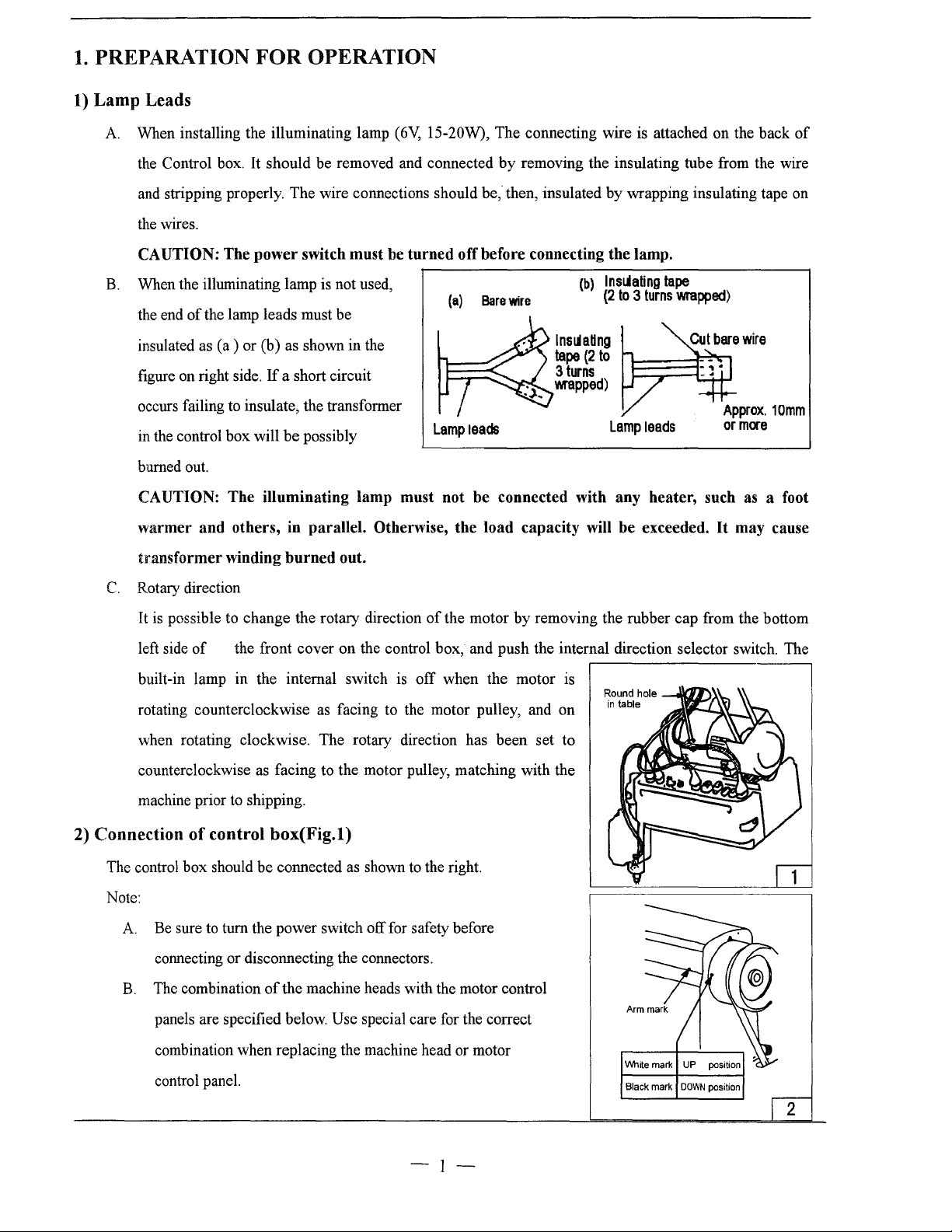
Lamp Leads
A.
When installing the illuminating lamp
FOR
OPERATION
(6V,
15-20W), The connecting wire is attached on the
back
of
the Control box. It should
and stripping properly.
the wires.
be
removed and connected
The
wire connections should
by
removing the insulating tube from the wire
be,"
then, insulated
by
wrapping insulating tape on
CAUTION: The power switch must be turned off before connecting the lamp.
When the illuminating lamp is not used,
B.
the end
insulated as (a ) or (b) as shown in the
figure on right side.
occurs failing to insulate, the transformer
in the control
burned out.
of
the lamp leads must
If
a short circuit
box
will
be
possibly
be
(a)
Lamp
Bare
leads
wire
(b)
lns~ating
(2
lnsl.daHng
tape
(2
to
3
turns
\\fapped)
Lamp
to
3
turns
leads
CAUTION: The illuminating lamp must not be connected with any heater, such
warmer and others, in parallel. Otherwise, the load capacity will be exceeded.
transformer winding burned out.
C.
Rotary direction
tape
wrapped)
as
It
may cause
a foot
2)
Connection
The control
Note:
A.
B.
It
is
possible to change the rotary direction
left side
built-in lamp
rotating counterclockwise as facing to the motor pulley, and on
when rotating clockwise. The rotary direction has
counterclockwise as facing to the motor pulley, matching with the
machine prior to shipping.
of
the front cover on the control box, and
in
the internal switch is
of
control box(Fig.l)
box
should
be
connected as shown to the right.
Be sure to turn the power switch off for safety before
connecting or disconnecting the connectors.
The combination
panels are specified below.
combination when replacing the machine head or motor
of
the machine heads with the motor control
Use special care for the correct
of
the motor
push
off
when the motor is
been
by
removing the rubber
the internal direction selector switch. The
set to
cap
from the bottom
control panel.
-I-
Black
mark
DOWN
position
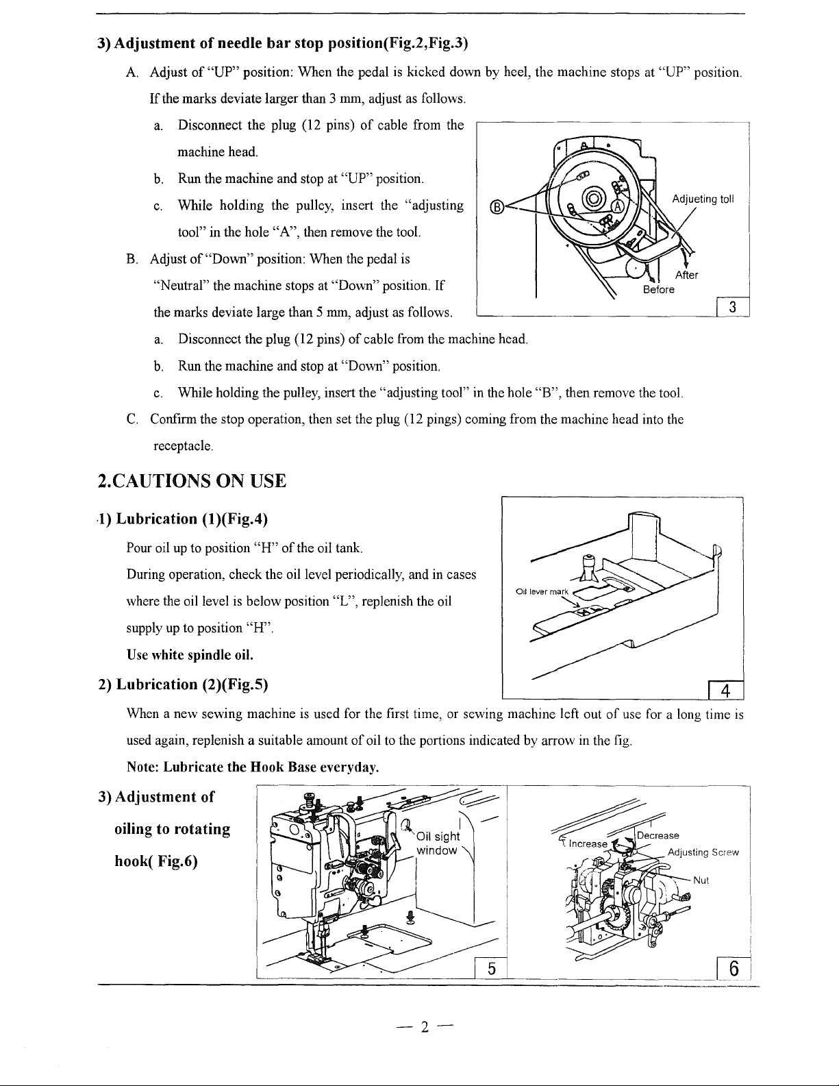
3)
Adjustment
A.
Adjust
If
a.
b.
c.
B.
Adjust
of
needle
of
"UP"
the marks deviate larger than 3 mm, adjust
Disconnect the plug (12 pins)
machine head.
Run the machine and stop at
While holding the pulley, insert the "adjusting
tool" in the hole
of
"Down" position: When the pedal is
bar
stop position(Fig.2,Fig.3)
position: When the pedal
of
cable from the
"UP"
position.
"A",
then remove the tool.
is
kicked down by heel, the machine stops at
as
follows.
®
"UP"
position.
Adjueting toll
"Neutral" the machine stops at "Down" position.
the marks deviate large than 5
a.
Disconnect the plug (12 pins)
b.
Run the machine and stop at "Down" position.
c.
While holding the pulley, insert the "adjusting tool" in the hole
C.
Confirm the stop operation, then set the plug (12 pings) coming from the machine head into the
receptacle.
mm,
adjust
as
follows.
of
cable from the machine head.
2.CAUTIONS ON USE
-1)
Lubrication
Pour oil
During operation, check the oil level periodically, and in cases
where the oil level is below position "L", replenish the oil
supply
Use white spindle oil.
(1
)(Fig.4)
up
to position
up
to position "H".
"H"
of
the oil tank.
If
"B",
then remove the tool.
2) Lubrication (2)(Fig.5)
When a new sewing machine
used again, replenish a suitable amount
Note:
Lubricate
3) Adjustment
of
the
Hook
is
used for the first time, or sewing machine left out
of
oil
to
the portions indicated by arrow in the
Base everyday.
oiling to rotating
hook( Fig.6)
-2-
of
use for a long time
fig.
is
4)
Condition of oil lubrication (Fig.5):
While operating the machine, check the condition
5)
Cautions on operation
A When the power is turned on or off, keep foot away from the pedal.
It
should be noted that the brake may not work when the power is interrupted or power failure occurs
B
during sewing machine operation.
C Since dust in the control
box cover close during operation.
D Do not apply a multimeter to the control circuit for checking; otherwise voltage
damage semiconductor components in the circuit.
box
might cause malfunction or control troubles, be sure to keep the control
of
oil lubrication through
the
3.0PERATION
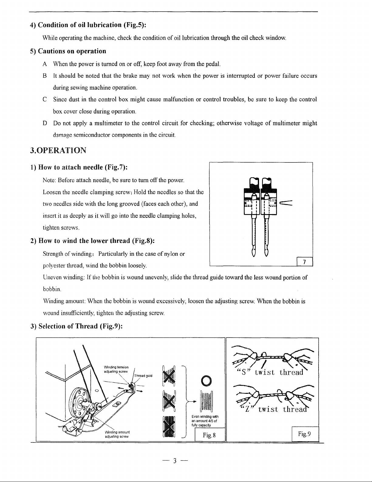
1)
How to
Note: Before attach needle, be sure to
Loosen the needle clamping screw; Hold the needles so that the
two needles side with the long grooved (faces each other), and
attach
needle (Fig. 7):
tum
off the power.
oil check window.
of
multimeter might
as
insert it
tighten screws.
2)
How to wind the lower
Strength
polyester thread,
Uneven winding:
bobbin.
Winding amount: When the bobbin
wound insufficiently, tighten the adjusting screw.
3) Selection of
deeply as it will go into the needle clamping holes,
thread
of
winding: Particularly in the case
\Vind
the bobbin loosely.
If
the bobbin is wound unevenly, slide the thread guide toward the less wound portion
Thread
(Fig.9):
(Fig.S):
is
Thread
of
nylon or
wound excessively, loosen the adjusting screw. When the bobbin
guid
0
7
of
is
Even
winding
With
-
an amount
4/5
of
Fig.8
\/Vindlng
amount
adjusting screw
I
-·
fully capacny
3-
Fig.9
It
is recommended to use
right needle.
"S"
twist thread in the left needle (Viewed from front), and
"Z"
twist thread in the
When discriminate use
"S"
twist thread as well as
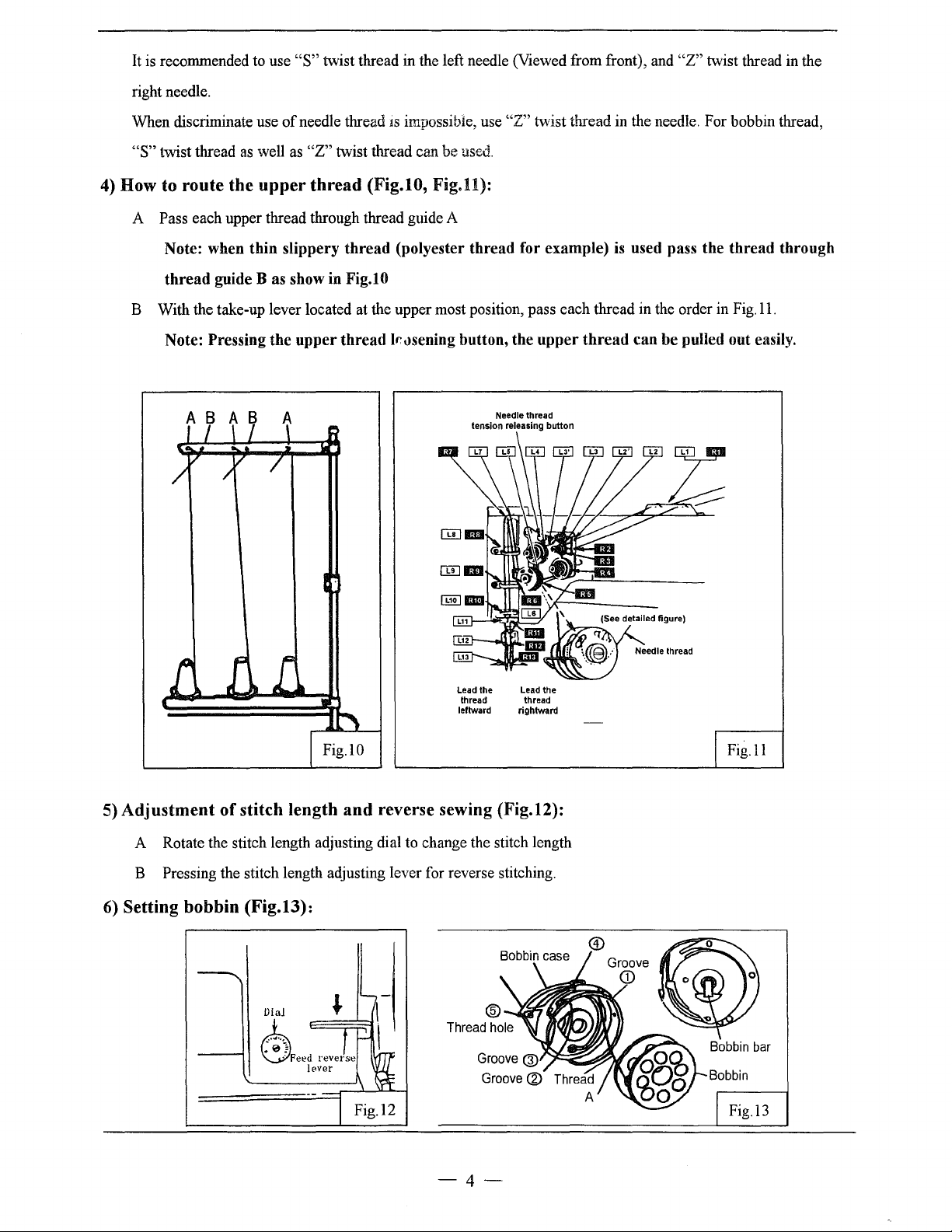
4)
How to route the
A Pass each upper thread through thread guide A
Note: when thin slippery thread (polyester thread for example)
thread guide
B With the take-up lever located at the upper most position, pass each thread in the order in
Note: Pressing the upper thread
A 8 A 8
of
needle thread
"Z"
upper
Bas
thread
show in Fig.lO
1s
impossible, use
twist thread can be used.
(Fig.lO,
Fig.ll):
lt:t~sening
button, the upper
tension releasing button
"Z"
twist thread in the needle. For bobbin thread,
is
used pass the thread through
thread
Needle thread
can be pulled out easily.
Fig.ll.
Lead the Lead the
thread thread
leftward rightward
5)
Adjustment
A Rotate the stitch length adjusting dial to change the stitch length
B Pressing the stitch length adjusting lever for reverse stitching.
6)
Setting bobbin (Fig.13):
of
stitch length
and
reverse sewing (Fig.12):
Fig.ll
-4-
Leading the lower thread and install the bobbin
Pull out thread from side
to
rotating hook, then replace hook shaft; Press the bobbin bar, leading the lower thread over bedplate.
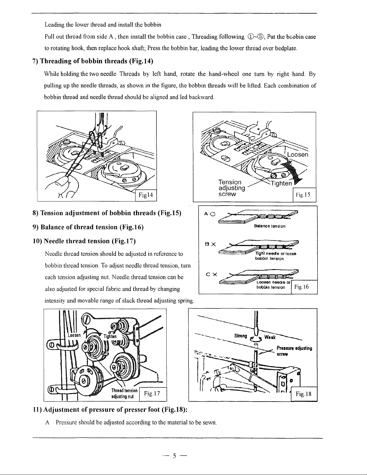
7)
Threading
While holding the two needle Threads
pulling up the needle threads,
bobbin thread and needle thread should be aligned and led backward.
of
bobbin
A,
then install the bobbin
threads
(Fig.14)
by
as
shown in the figure, the bobbin threads will be lifted. Each combination
case,
Threading following
left hand, rotate the hand-wheel one turn
Tension
adjusting
screw
CD-®;
Put the bc,obin case
by
right hand. By
of
8) Tension
9)
Balance
10) Needle
Needle thread tension should be adjusted in reference to
bobbin thread tension.
each tension adjusting nut. Needle thread tension can be
also adjusted for special fabric and thread by changing
intensity and movable range
adjustment
of
thread
thread
tension (Fig.16)
tension (Fig.17)
of
bobbin
To
adjust needle thread tension, tum
threads
of
slack thread adjusting spring.
(Fig.15)
AQ/"~33~
Balance tension
BX
~~~I~
E:=
Ti;h't needle or loose
bobbin tension
cx.<~----1
bobbin tension I Fig.l6
~---
~~-r~
}(-~·
1
! (
11)
Adjustment
A Pressure should be adjusted according to the material to be sewn.
of pressure
of
presser foot (Fig.18):
-5-
B Turning the pressure adjusting screw to adjust the pressure
of
presser foot
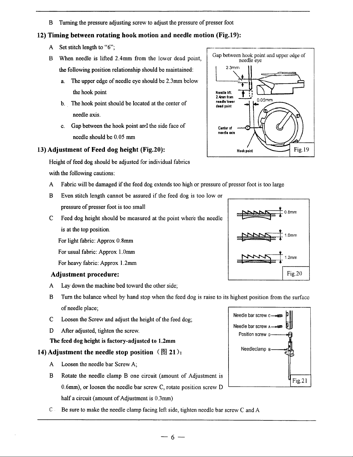
12) Timing between rotating hook motion
A Set stitch length to
B When needle is lifted 2.4mm from the lower dead point,
the following position relationship should be maintained:
a.
The upper edge
the hook point
b.
The hook point should be located at the center
needle axis.
c.
Gap between the hook point and the side face
needle should be 0.05 mm
13) Adjustment
Height
with the following cautions:
A Fabric will be damaged
B Even stitch length cannot be assured
of
of
feed dog should be adjusted for individual fabrics
"6";
of
needle eye should be 2.3mm below
Feed dog height (Fig.20):
if
the feed dog extends too high or pressure
and
needle motion (Fig.19):
if
the feed dog
of
of
is
too low or
·--------~--------,
Gap between hook point and upper edge
LS~
.....
2.4rm1
needle
dead
Center
needle
needle eye
,
..
\=:~~
from
___:.·
lower
point
of
uis
of
presser foot is too large
of
of
pressure
C Feed dog height should be measured at the point where the needle
is at the top position.
For light fabric: Approx
For usual fabric: Approx l.Omm
For heavy fabric: Approx 1.2mm
Adjustment procedure:
A Lay down the machine bed toward the other side;
B Turn the balance wheel
of
needle place;
C Loosen the Screw and adjust the height
D After adjusted, tighten the screw.
The
feed dog height is
14) Adjustment the needle stop position (
A Loosen the needle bar Screw A;
presser foot is too small
0.8mm
by
hand stop when the feed dog
factory-adjusted
of
the feed dog;
to
1.2mm
00
21
):
w~I0.8mm
~11.0mm
1
a~m
I
1.2mm
I Fig.20
is
raise to its highest position from the surface
Needle
bar
screw
Needle
bar
Position
Needleclamp
screw
screw
,__
A_.,.
o
B
~
~0
~
B Rotate the needle clamp B one circuit (amount
0.6mm), or loosen the needle bar screw
of
half a circuit (amount
C Be sure
to
make the needle clamp facing left side, tighten needle bar screw C and A
Adjustment is 0.3mm)
C,
of
Adjustment is
rotate position screw D
-6-
Fig.21
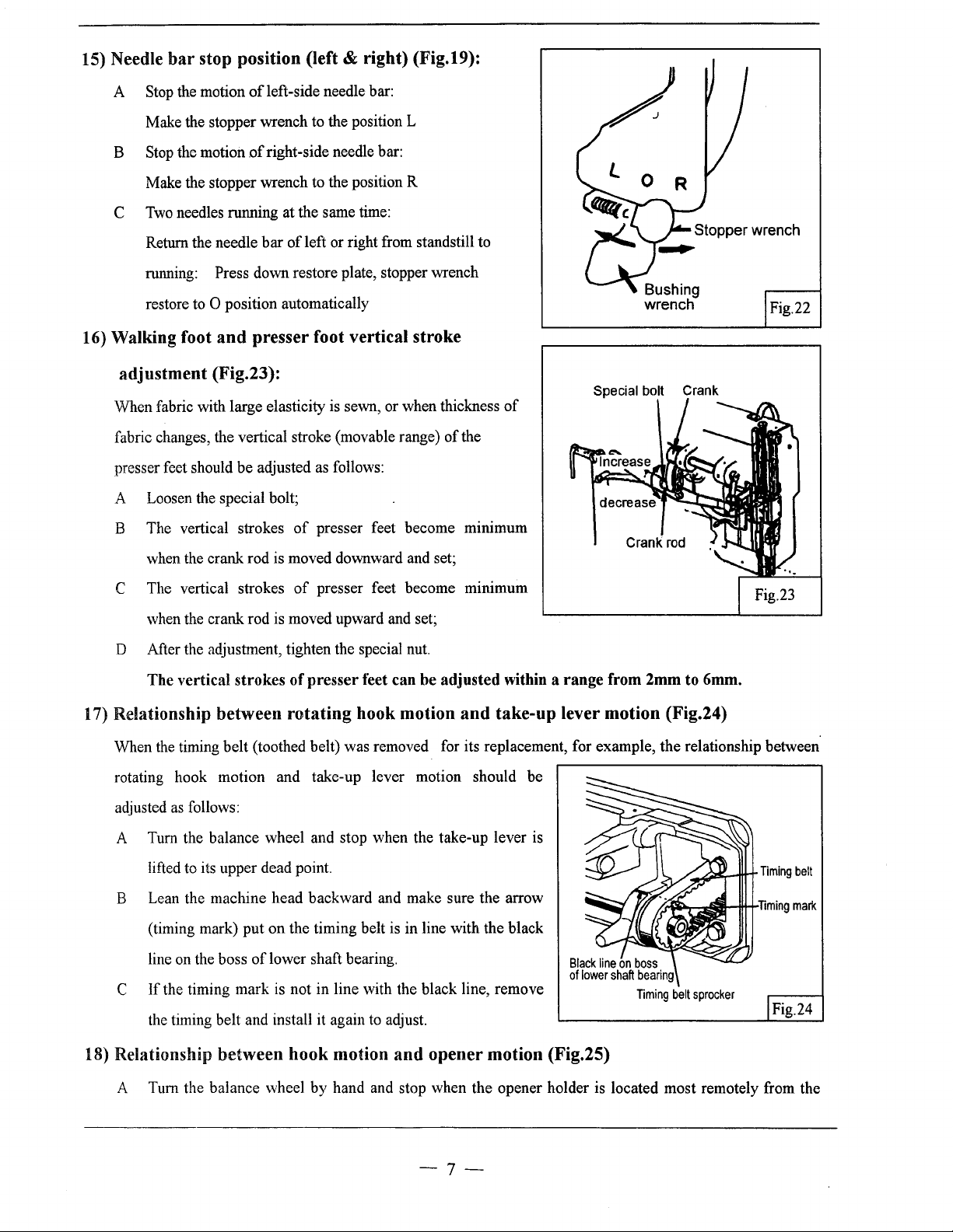
15) Needle
bar
stop position (left & right) (Fig.19):
A Stop the motion
Make the stopper wrench to the position L
B Stop the motion
Make the stopper wrench to the position R
C
Two
needles running at the same time:
Return the needle bar
running:
restore to
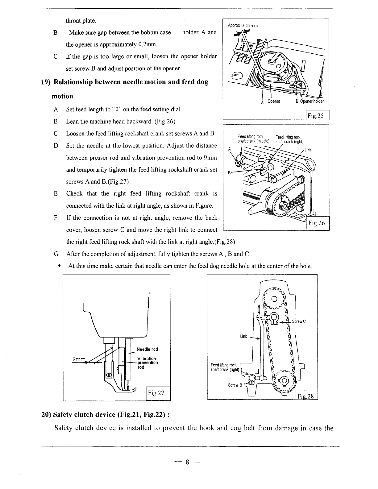
16) Walking foot
of
left-side needle bar:
of
right-side needle bar:
of
left or right from standstill to
Press down restore plate, stopper wrench
0 position automatically
and
presser foot vertical stroke
adjustment (Fig.23):
When fabric with large elasticity is sewn, or when thickness
fabric changes, the vertical stroke (movable range)
as
presser feet should be adjusted
A Loosen the special bolt;
B The vertical strokes
when the crank rod is moved downward and set;
follows:
of
presser feet become mtmmum
of
the
of
Special bolt Crank
Crank
rod
Fig.22
C The vertical strokes
when the crank rod is moved upward and set;
of
presser feet become mtmmum
D After the adjustment, tighten the special nut.
The
vertical
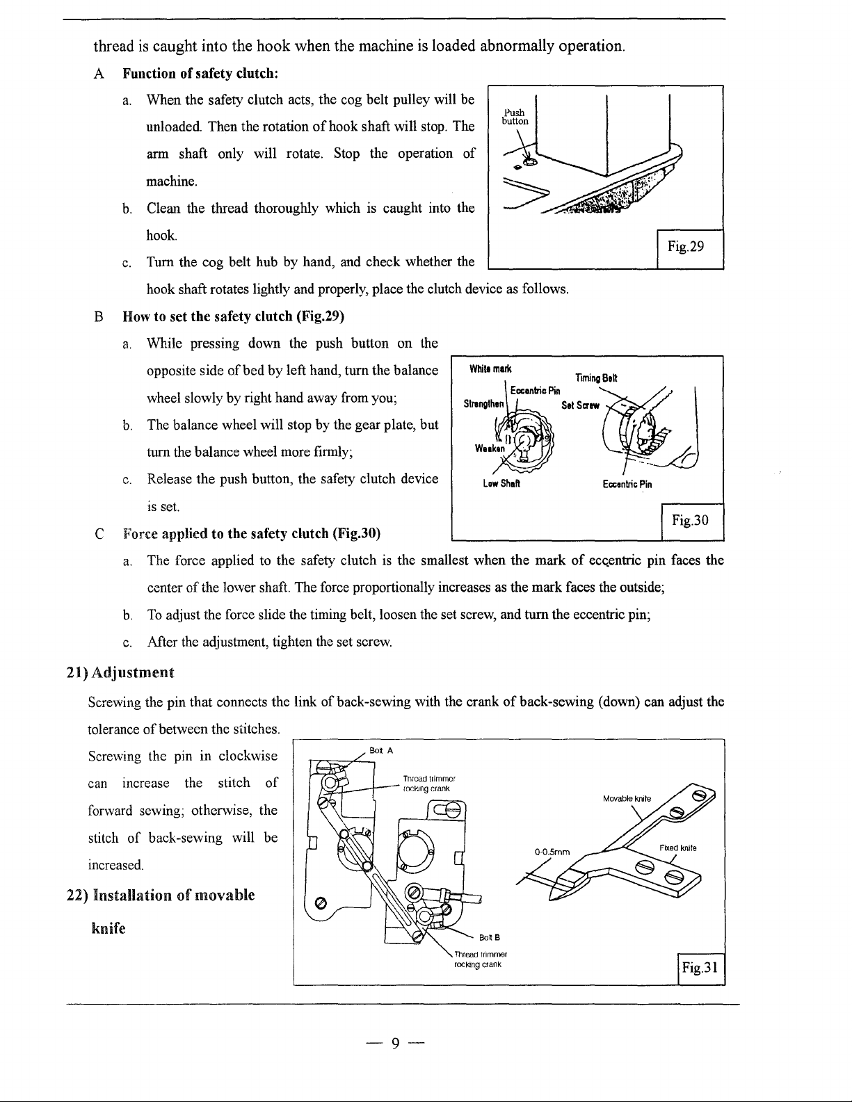
17) Relationship between rotating hook motion
When
the
timing belt (toothed belt) was removed for its replacement, for example, the relationship between
rotating hook motion and take-up lever motion should be
as
adjusted
A Tum the balance wheel and stop when the take-up lever is
B Lean the machine head backward and make sure the arrow
C
follows:
to
lifted
(timing mark) put on the timing belt is in line with the black
line on the boss
If
the timing mark is not in line with the black line, remove
the timing belt and install it again to adjust.
strokes
its upper dead point.
of
presser
of
lower shaft bearing.
feet can be
adjusted
and
within a
range
from
2mm
to
6mm.
take-up lever motion (Fig.24)
Timing
belt
sprocker
Timing
Fig.24
mark
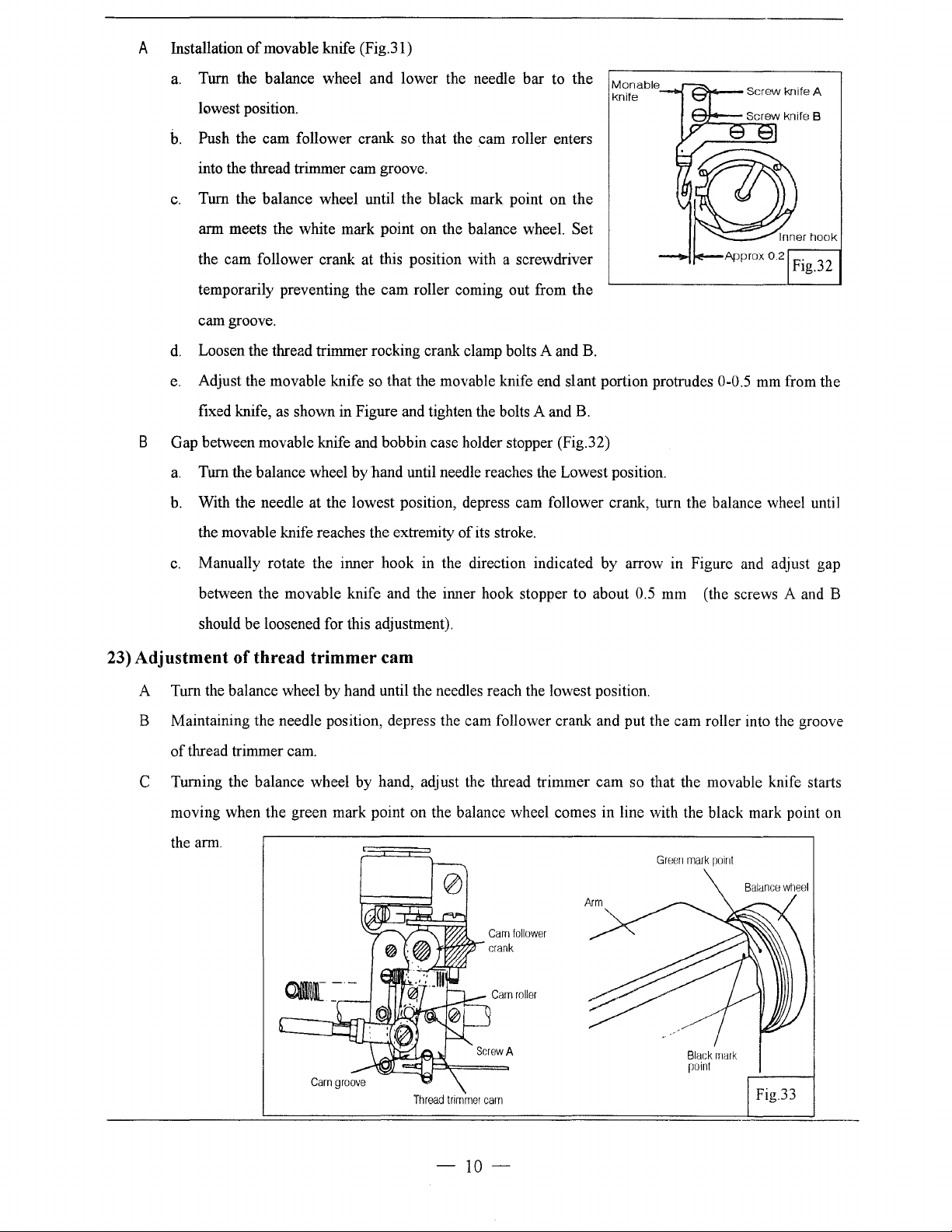
18) Relationship between hook motion
A Tum the balance wheel by hand and stop when the opener holder is located most remotely from the
and
opener motion (Fig.25)
-7-
throat plate.
Make sure gap between the bobbin case
B
the opener is approximately 0.2mm.
C
If
the gap is too large or small, loosen the opener holder
set screw B and adjust position
of
the opener.
holder A and
Approx
0
2mm
19) Relationship between needle motion
and
feed dog
motion
A Set feed length to
B Lean the machine head backward. (Fig.26)
C Loosen the feed lifting rockshaft crank set screws A and B
D Set the needle at the lowest position. Adjust the distance
between presser rod and vibration prevention rod
and temporarily tighten the feed lifting rockshaft crank set
screws A and B.(Fig.27)
Check that the right feed lifting rockshaft crank is
E
connected with the link at right angle,
If
F
the connection
cover, loosen screw
the right feed lifting rock shaft with the link at right angle.(Fig.28)
G After the completion
"0"
on the feed setting dial
as
shown in Figure.
is
not at right angle, remove the back
C and move the right link
of
adjustment, fully tighten the screws A , B and
to
to
connect
9mm
Fig.25
Feed
lifting
rock
shaft
crank
(middle)
A
B
Feed
shaft
lifting
crank
rock
(right)
C.
dog
• At this time make certain that needle can enter the feed
Needle
rod
Vibration
prevention
rod
needle hole at the center
Feed
lifting
rock
shaft
crank
(right)
Fig.27
20) Safety clutch device (Fig.21, Fig.22) :
Safety clutch device is installed to prevent the hook and cog belt from damage
of
the hole.
in
case the
-8-
thread
is
caught into the hook when the machine
A Function of safety clutch:
a.
When the safety clutch acts, the cog belt pulley will be
unloaded. Then the rotation
of
hook shaft will
is
loaded abnormally operation.
Push
stop.
The
button
ann shaft only will rotate. Stop the operation
machine.
b.
Clean the thread thoroughly which
is
hook.
c.
B
Turn the cog belt hub by hand,
hook shaft rotates lightly
How
to set the safety clutch (Fig.29)
a.
While pressing down the push button on the
and
and
check whether the
properly, place the clutch device
opposite side of bed by left hand, turn the balance
wheel slowly by right hand away from you;
b.
The balance wheel will stop by the gear plate, but
turn
the balance wheel more firmly;
c.
Release the push button, the safety clutch device
is
set.
C Force applied to the safety clutch (Fig.30)
of
caught into the
White
Low
as
mark
Shaft
follows.
Eccentric
Pin
Set
Timing
Screw
Be~
Eccentric
Fig.29
Pin
Fig.30
a.
21)
Adjustment
The force applied
center
of
b.
To
adjust the force slide the timing belt, loosen the set screw, and
c.
After
the
the lower shaft. The force proportionally increases
adjustment, tighten the set screw.
to
the safety clutch
is
the smallest when the mark
Screwing the pin that connects the link of back-sewing with the crank
tolerance ofbetween the stitches.
Screwing the pin in clockwise
Thread
can
mcrease the stitch
of
trimmer
roc~Jng
crank
forward sewing; otherwise, the
stitch
of
back-sewing will be
increased.
22) Installation
of
movable
knife
of
ec<;,entric
as
the mark faces the outside;
turn
the eccentric pin;
of
back-sewing (down) can adjust the
pin faces the
-9-
Fig.31
A Installation
a.
Tum the balance wheel and lower the needle bar to the
lowest position.
b.
Push the cam follower crank
into the thread trimmer cam groove.
c.
Tum the balance wheel until the black mark point on the
arm meets the white mark point on the balance wheel. Set
the cam follower crank at this position with a screwdriver
temporarily preventing the cam roller coming out from the
cam groove.
d.
Loosen the thread trimmer rocking crank clamp bolts A and
e.
Adjust the movable knife
of
movable knife (Fig.31)
so
Monable
knife
so
that the cam roller enters
B.
that the movable knife end slant portion protrudes 0-0.5
mm
from the
fixed knife,
as
shown in Figure and tighten the bolts A and
B.
B Gap between movable knife and bobbin case holder stopper (Fig.32)
a.
Tum the balance wheel by hand until needle reaches the Lowest position.
b.
With the needle at the lowest position, depress cam follower crank, turn the balance wheel until
of
the movable knife reaches the extremity
c.
Manually rotate the inner hook in the direction indicated by arrow in Figure and adjust gap
between the movable knife and the inner hook stopper to about
its stroke.
0.5
mm (the screws A and B
should be loosened for this adjustment).
23) Adjustment
of
thread trimmer cam
A Turn the balance wheel by hand until the needles reach the lowest position.
B Maintaining the needle position, depress the cam follower crank and put the cam roller into the groove
of
thread trimmer cam.
C Turning the balance wheel by hand, adjust the thread trimmer cam so that the movable knife starts
moving when the green mark point on the balance wheel comes in line with the black mark point on
the
arm.
Green
mark
point
Cam
follower
crank
Cam
roller
Thread
trimmer
cam
-10-
Black
point
mark
Fig.33
Note:
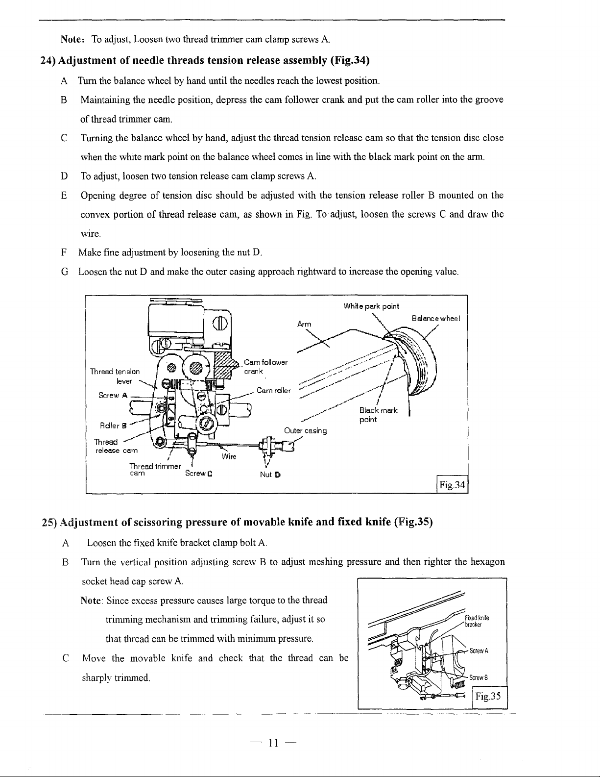
24)
Adjustment
A Turn the balance wheel by hand until the needles reach the lowest position.
B Maintaining the needle position, depress the cam follower crank and
To
adjust, Loosen two thread trimmer cam clamp screws A
of
of
thread
needle
trilThller
threads
cam.
tension release assembly (Fig.34)
put
the cam roller into the groove
C Turning the balance wheel
when the white mark point on the balance wheel comes in line with the black mark point on the arm.
To
D
E
F Make fine adjustment by loosening the nut
G Loosen the nut D and make the outer casing approach rightward to increase the opening value.
adjust, loosen two tension release cam clamp screws A
Opening degree
convex portion
wire.
of
tension disc should be adjusted with the tension release roller B mounted on the
of
thread release cam,
by
hand, adjust the thread tension release
as
shown in Fig. To· adjust, loosen the screws C and draw the
D.
White
cam
so that the tension disc close
park
point
point
Thread
release
cam
'
Screw
C:
Nut
D
of
movable knife
and
fixed knife (Fig.35)
Fig.34
25)
Adjustment
Thread trimmer
cam
of
scissoring pressure
A Loosen the fixed knife bracket clamp bolt A
B Tum the vertical position adjusting screw B to adjust meshing pressure and then righter the hexagon
socket head cap screw A
to
Note: Since excess pressure causes large torque
trimming mechanism and trimming failure, adjust it
that thread can be trimmed with minimum pressure.
C Move the movable knife and check that the thread can be
sharply trimmed.
the thread
so
Fig.35
-II-
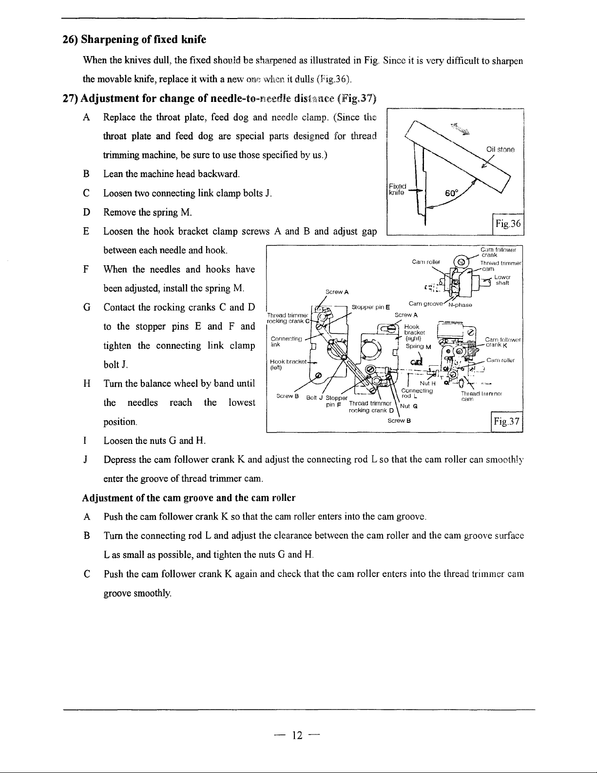
26)
Sharpening
of
fixed knife
When the knives dull, the fixed shovld
the movable knife, replace it with a
27)
Adjustment
for
change
of
needle-to-needle dishuu:e (Fig,37)
be
sharpened as illustrated in Fig. Since it is very difficult to sharpen
ne\V
one when it dulls (Fig.36).
A Replace the throat plate, feed dog and needle clamp. (Since
throat plate and feed dog are special parts designed for thread
trimming machine, be sure to use those specified by us.)
B Lean the machine head backward.
C Loosen two connecting link clamp bolts
D Remove the spring
M.
J.
E Loosen the hook bracket clamp screws A and B and adjust gap
between each needle and hook.
F When the needles and hooks have
been adjusted, install the spring
M.
G Contact the rocking cranks C and D
to the stopper pins
tighten the connecting link clamp
J.
bolt
E and F and
Cnnner.tino
link
Hook
bracket
(left)
the
r
Lower
shaft
H Turn the balance wheel
the needles reach the lowest
position.
Loosen the nuts G and H.
J Depress the cam follower crank K and adjust the connecting rod L so that the cam roller can smoothly
enter the groove
of
by
band until
thread trimmer cam.
Screw B
Screw B
Fig.37
Adjustment of the cam groove and the cam roller
A Push the cam follower crank K so that the cam roller enters into the cam groove.
cam
B Tum the connecting rod L and adjust the clearance between the
Las
small as possible, and tighten the nuts G and
C Push the cam follower crank K again and check that the cam roller enters into the thread trimmer cam
groove smoothly.
H.
roller and the cam groove surface
-12-
 Loading...